del - hiab · del equipment (uk) ltd installation manual – tuckunder lifts 11 issue j 7. connect...
TRANSCRIPT

DEL
INSTALLATION MANUAL TUCKUNDER TAILIFTS
DEL EQUIPMENT (U.K.) LTD Building 1, Windrush Park Road
Windrush Industrial Park, Witney Oxon, OX29-7HA
TEL: 01993 708811 FAX: 01993 708787
EMAIL: [email protected] WEBSITE: www.del-uk.com
DEL IS A CARGOTEC BRAND
P/No. 51189 – Issue J

Del Equipment (UK) Ltd Installation Manual – Tuckunder Lifts
2 Issue J
DEL
EC DECLARATION OF CONFORMITY FOR MACHINERY
We hereby declare that:
DEL Tailift Model: DA
are in conformity with the provisions of the Machinery Directive (2006/42/EC)
and furthermore declare that parts of the following European harmonised standards have been used:
BS EN 1756-1:2001 + A1: 2008
Signed:
Name: Ian Forman
Position: Managing Director, DEL Equipment (UK) Ltd.
Place, Date: Witney, OX29 7HA, 29th December 2009
Important:
This declaration is null and void without a completed Lift Installation Test Certificate attached and all signatures completed, or if modifications are made to the machine without prior written approval from Del Equipment (UK) Ltd.
DEL EQUIPMENT (U.K.) LTD Building 1, Windrush Park Road
Windrush Industrial Park, Witney Oxon, OX29-7HA
TEL: 01993 708811 FAX: 01993 708787
EMAIL: [email protected] WEBSITE: www.del-uk.com

Del Equipment (UK) Ltd Installation Manual – Tuckunder Lifts
3 Issue J
IMPORTANT
ENSURE THAT THE FITTING PLATE (SHOWN BELOW) IS FITTED BETWEEN
THE RAM PINS BEFORE INSTALLATION. THIS WILL HOLD THE
RAM A FEW MM OPEN. HOLD THE PLATES IN PLACE WITH
THE R-CLIPS PROVIDED

Del Equipment (UK) Ltd Installation Manual – Tuckunder Lifts
4 Issue J
INTRODUCTION
This manual covers the installation and testing of the ‘Tuckunder’ tailift model. The correct installation and setting up of the lift is vital to the working life of the lift. Safety must be regarded as of paramount importance during installation. Read this manual fully before commencing work. The lift frame and platform are heavy and can crush. Never work under the lift unless it is securely supported and always disconnect the battery before starting work.
Do not make any design modification to the tailift unless written permission is first obtained from DEL Equipment (UK) Ltd.
Please note that any unauthorised modification may: -
Invalidate the warranty
Lead to equipment failure
Create a hazard that is not immediately obvious at the time of installation.
If you are unsure about any aspect of the installation procedure, please contact DEL service.
IMPORTANT
This manual forms part of the Inspection record for the tailift, and should be passed on to the end user, together with the operator’s manual.
1. X and Y – Dimension
The ‘X’ and ‘Y’ dimension given in this manual is intended as a guide only.
As long as the lift is installed following the checking procedure in this manual, the lift will operate correctly. The tolerance on the ‘X’ and ‘Y’ dimension is therefore ± 25mm.
2. Floor Plate
On new vehicles it is normal to fit the floor plate as part of the floor and lower rear frame member. On existing vehicles the floor plate can be added to the rear, check the legal overhanging requirements prior to fitting.
3. Power Pack
The tailift is delivered with the power pack fully installed and tested.

Del Equipment (UK) Ltd Installation Manual – Tuckunder Lifts
5 Issue J
CONTENTS
EC DECLARATION OF CONFORMITY FOR MACHINERY ....................................... 2
INTRODUCTION ........................................................................................................ 4
CONTENTS ............................................................................................................... 5
1. OPERATING SYSTEMS ................................................................................. 6
2. INSTALLATION PROCEDURE ....................................................................... 7
3. WARNING DECALS ...................................................................................... 14
4. INSTALLATION OF IN-LINE FUSE & EARTH............................................... 16
5. POWER PACK RELIEF VALVE .................................................................... 17
6. LOCATION OF THE CONTROL POSITION .................................................. 17
7. TESTS AFTER INSTALLATION .................................................................... 18
8. TECHNICAL INFORMATION ........................................................................ 21
9. FINAL INSPECTION CHECKLIST ................................................................. 23
10. WIRING DIAGRAM ........................................................................................ 24
11. HYDRAULIC DIAGRAM ................................................................................ 25
DEL WARRANTY REGISTRATION FORM .............................................................. 26
LIFT TEST CERTIFICATE ........................................................................................ 27

Del Equipment (UK) Ltd Installation Manual – Tuckunder Lifts
6 Issue J
1. OPERATING SYSTEMS
The tailift is powered from the vehicle battery. A wire is taken from the battery positive to the powerpack starter switch and the hand control, these circuits are protected by in-line fuses. The up button on the hand control provides power to the starter switch, which operates the powerpack motor. This pumps high-pressure hydraulic fluid to retract the ram. On release of the up button the fluid is held in the ram due to a non return valve which locks the ram in position therefore holding the platform stationary. Pushing the down button powers the lowering solenoid, which allows the hydraulic fluid back from the ram to the power pack reservoir. When not in use the platform is folded in upon itself and ‘tucks away’ under the rear of the vehicle. A lock valve is used to hold the ram in position and keep the platform securely stowed under the vehicle against its stop.

Del Equipment (UK) Ltd Installation Manual – Tuckunder Lifts
7 Issue J
2. INSTALLATION PROCEDURE
1. Disconnect the battery and remove the lights and wiring harness from the back of the vehicle.
2. With the vehicle unladen, measure the distance from the ground to the vehicle floor level. This is the vehicle unladen bed height. Check that the lift model is suitable for that lift height.
Lift model Lowest (laden) floorheight (mm)
Highest (unladen) floorheight (mm)
DA1500 Twin Ram 1120 1440
DA1000H 1120 1400
DA1000L 915 1190
3. On DA1000L Tuckunder lifts, confirm what size of fixed platform the lift has. It will be either 22” (DA1000LG/A), 24” (DA1000LG/B) or 26” (DA1000LG/C) long. This will enable the correct cut out dimensions to be used.

Del Equipment (UK) Ltd Installation Manual – Tuckunder Lifts
8 Issue J
4. Use the chart below to obtain the ‘Y’ reference dimension needed in mounting the tailift (see the note at the start of this manual). Also check the ‘S’ reference dimension for interference with spring hangers.
Model ‘Y’ ref. (mm) ‘X’ ref. (mm) ‘S’ ref. (mm)
DA1500 572 929 1146
DA1000H 572 920 1138
DA1000L
22”
499 803
994
24” 1036
26.75” 1086
Dimension Y – Distance from the bed of the vehicle to the top of the tailift beam, reference only.
Dimension X – Distance from the front of the floor plate to the back of the tailift beam, reference only.
NOTE
The minimum clearance required between the tailift housing and the truck tyres is 125mm
Minimum bed height is with the vehicle fully loaded.
Maximum bed height is with the vehicle empty.

Del Equipment (UK) Ltd Installation Manual – Tuckunder Lifts
9 Issue J
5. Cut away or add to the chassis to obtain the dimensions required for your vehicle. The installation of all tuckunder lifts allow for a 20mm floor, 100mm bearer and 100mm runner
DA1500 AND DA1000H TUCKUNDER CHASSIS CUT OUT
DA1000L TUCKUNDER CHASSIS CUT OUT
6. Build in the floor plate to the rear frame keeping the centre of the floor plate in the centre of the vehicle (it may be necessary to cut both ends of the floor plate). The top of the floor plate is set to match the vehicle floor level

Del Equipment (UK) Ltd Installation Manual – Tuckunder Lifts
10 Issue J
Fitting of lock equipment to the floor plate
‘Barn door’ type bodies
The floor plate and lift have been designed to allow the attachment of door locks to the outer face of the floor plate. If this is done, the front edge of the platform should be machined out to allow the platform to sit flush with the floor when in operation.
Roller shutter door bodies
The floor plate can be cut to allow for the roller shutter lock plate to be welded in. The floor plate will need to be cut on its top and bottom surface to allow the shutter hook to pass through. The hole in the underside of the floor plate should have its sides plated in with 4mm steel sheet. This will help retain the strength of the floor plate in the area of the lock and stop water ingress.
Note – Care must be taken to ensure that the heat from welding does not excessively warp the floor plate

Del Equipment (UK) Ltd Installation Manual – Tuckunder Lifts
11 Issue J
7. Connect the lift to a slave battery before pressing the down button to allow the lift platform to be unfolded
8. Position the fitting plate/s over the ram pin's and secure using the R-clips
provided. This will hold the ram/s approx 6mm open for installation. 9. Using a chain lift, fork lift or overhead crane raise the platform to the rear of the
vehicle. Position the platform so that it is 4mm above the top of the floor plate before clamping the platform to the floor plate.
Swing the tailift beam under the vehicle body, so that the mounting plates fit either side of the chassis. Ensure that the lift is positioned central about the chassis. If the gap between the mounting plates and the chassis exceeds 2mm each side, a shim should be inserted between the mounting plate and the chassis. Using a trolley jack, adjust the position of the beam ensuring that the top of the beam is parallel with the floor of the vehicle.
At this point, check the following (see drawing below)
a) The platform is positioned 4mm above the top of the floor plate b) The beam is parallel to the floor of the vehicle c) The fitting plate/s are installed holding the ram/s approx 6mm open d) The adjustor bolt is touching the stop plate, giving a platform angle of approx
4 degrees.

Del Equipment (UK) Ltd Installation Manual – Tuckunder Lifts
12 Issue J
e) Check the ‘X’ and ‘Y’ reference dimensions for your lift. As these are reference dimensions, a tolerance of ±25mm is acceptable.
10. When correctly positioned, if the chassis runner is steel, run 3 off 1” long stitch welds around the top of the mounting plate, welding it to the runners both sides. Also bolt the mounting plate to the chassis with one bolt each side only.
If the runner is aluminium or cannot be welded, bolt the mounting plates to the runner and chassis with 3 bolts each side only (ensure a large span of bolts)
Use the bolts provided with the lift, these are
M12 bolts – DA1000 lifts, drill diameter 12mm holes
M16 bolts – DA1500 lifts, drill diameter 16mm holes
Ensure the bolts are tightened to the torque specified in the ‘Technical Information’ section of this manual.
This process will allow the fitment of the lift to be checked before it is fully fitted.
11. Complete the tailift wiring following the circuit diagram given. Fix the position of the hand control in a position which allows a good view of the working area of the lift.
12. Remove the clamps holding the platform to the floor plate, and any crane/fork lift holding the platform.
13. Remove the fitting plate between the ram pins.
14. Adjust the underun bar bracket (the underside of the underun bar must be no more than 550mm above ground)
15. Run the tailift through its complete cycle to ensure correct operation.
FITTING PLATE BETWEEN
RAM PINS

Del Equipment (UK) Ltd Installation Manual – Tuckunder Lifts
13 Issue J
CAUTION
The lift is not completely fitted, DO NOT enter the working area of the lift, hold the lift at relief pressure when fully raised, or apply a load to the platform.
During this check, ensure
a) The platform comes up to the floor of the vehicle square and level, and is still set 1 to 4mm above floor level
b) The platform lowers to the ground, and has its ramp touching the ground when fully lowered.
c) The lift stows correctly, clearing the cut out in the chassis and any bodywork (e.g. steps) which may be fitted.
16. Finish the installation of the lift by fitting the remaining bolts through the mounting
plates to the chassis. The lift needs to have a minimum of
6 off M12 bolts each side – DA1000 lifts
6 off M16 bolts each side – DA1500 lifts
Ensure that all bolts are tightened to the correct torque, and that the greatest span of bolts as possible has been used.
17. Check the operation of the lift through its full range of motion 18. Carry out the post installation tests, which are detailed in the back of this manual.
The test sheets must remain in the manual, and be kept with the operators manual as part of the service/maintenance record for the lift. Complete the test certificate and forward a copy to DEL.
19. Once the vehicle has been painted, the Warning, Instruction and Safe Load
decals must be fitted. 20. Ensure that the manuals are passed on to the end user of the lift. 21. Complete the final inspection checklist.

Del Equipment (UK) Ltd Installation Manual – Tuckunder Lifts
14 Issue J
3. WARNING DECALS
1) EMERGENCY TAILIFT ISOLATION LOCATED AROUND THE POSITIVE CABLE TO THE BATTERY
2) ISOLATE POWER SUPPLY
LOCATED ON THE POWER PACK BOX 3) ELEVATING TAILIFT
LOCATED ON THE REAR PASSENGER SIDE OF THE VEHICLE AT EYE LEVEL
4) KEEP FEET CLEAR LOCATED ON THE EDGES OF BOTH
5) TAILIFT CAN CRUSH LOCATED ON THE FRONT FACE OF THE DOCKING BAY OR CORNER POSTS

Del Equipment (UK) Ltd Installation Manual – Tuckunder Lifts
15 Issue J
6) MAXIMUM LOAD (500KG SHOWN) LOCATED ON THE REAR PASSENGER SIDE OF THE VEHICLE AT EYE LEVEL
7) FLAG LOCATED ON THE UNDERSIDE OF THE FOLDING (RAMP) SECTION OF THE PLATFORM AT BOTH ENDS
8) TAILIFT OPERATION
LOCATED ON THE REAR PASSENGER SIDE OF THE VEHICLE AT EYE LEVEL

Del Equipment (UK) Ltd Installation Manual – Tuckunder Lifts
16 Issue J
4. INSTALLATION OF IN-LINE FUSE & EARTH
Route the main battery cables from tailift to the battery along the chassis avoiding the exhaust, fuel pipes and sharp edges.
Locate the fuse holder on the positive cable, as close to the battery as possible, inside the engine compartment using the short cable to the battery +ve terminal. Connect the negative cable to the battery.
Route the main battery cables from tailift to the battery along the chassis avoiding the exhaust, fuel pipes and sharp edges.
Locate the fuse holder inside the battery case, using bolts, not self-tappers. If insufficient space inside the case, locate as close to the battery as possible, in an area least susceptible to the elements.
Connect the negative cable to the battery.
IF YOU ARE UNSURE ON FITTING THE INLINE FUSE
PLEASE CONTACT DEL SERVICE

Del Equipment (UK) Ltd Installation Manual – Tuckunder Lifts
17 Issue J
5. POWER PACK RELIEF VALVE
The powerpack relief valve has been factory set, if for maintenance purposes the valve needs to be adjusted, please contact the DEL service department.
6. LOCATION OF THE CONTROL POSITION
The standard control for Tuckunder model lifts is the Wander lead control. The hand
control is plugged into the control socket located on the passenger side of the lift
before use. The hand control must be disconnected after use and locked inside the
drivers cab.

Del Equipment (UK) Ltd Installation Manual – Tuckunder Lifts
18 Issue J
7. TESTS AFTER INSTALLATION
After the lift has been initially installed the following tests MUST be completed to ensure the lift has been installed and set up correctly in accordance with CE regulations. The results of the test should be entered on the test certificate provided in the back of this manual and a copy returned to DEL Equipment (UK) Ltd, the original should be kept in the manual as part of the inspection record for the lift.
IMPORTANT - CE REGULATIONS REQUIRE THE TEST CERTIFICATE TO BE COMPLETED AND RETURNED TO DEL Equipment (UK) Ltd
1) Static weight tests
a) Deformation
This test is to ensure that the lift attachment is secure.
Lower the platform mid-way between ground level and vehicle floor level.
Measure the height of the platform from the vehicle floor (measurement A, B and C) as shown below and record the values in the table provided. Note that a bar clamped to the bed of the vehicle may be needed to aid measuring.
Do not leave a loaded
platform unattended

Del Equipment (UK) Ltd Installation Manual – Tuckunder Lifts
19 Issue J
Apply a load equal to the safe working load +25% to the platform, leave it for a few seconds before removing it (note that the power pack relief valve prevents this load from being lifted).
Re-measure the distances A, B and C and record under ‘measurement 1’ in the table below.
If the new values of A, B and C are not the same as the previous values repeat the test until they are, recording all subsequent tests in the spaces given.
Check that no permanent deformation has occurred in the lift or its attachment to the vehicle, which would affect its function.
Initial Measurement 1 Measurement 2 Measurement 3
A
B
C
b) Platform drift
This test is to ensure that the platform remains stationary within 15mm of its original position over a 15-minute test period.
Raise the platform to vehicle bed height.
Apply a load equal to the safe working load + 25% to the platform. (note that the power pack relief setting prevents this load from being raised)
Measure the distances A, B, and C and record them in the table provided.
Leave the platform loaded for 15 minutes.
After the 15 minutes test period, re-measure the values A’ to C’ and record them in the table.
Check that:
1. The difference in the measurements do not exceed 15mm
2. The difference between A’ and B’ does not exceed 70mm
3. The difference between A’ and C’ does not exceed 51mm Note the values given refer to the standard size platform of 1981mm wide by 1457mm deep. For other size platforms divide the difference between A’ and B’ by

Del Equipment (UK) Ltd Installation Manual – Tuckunder Lifts
20 Issue J
the width and the difference between A’ and C’ by the depth. The result of these should not be more than 0.035 (3.5%) of the width or depth as appropriate.
Initial Measurement After 15 minutes Measurement
A A’
B B’
C C’
2) Test to verify that the lift cannot raise excessive load
Lower the platform to Ground level.
Apply the safe working load + 25% to the platform.
Verify that the load cannot be lifted.
3) Dynamic weight test
Apply the safe working load to the platform.
Ensure that the lift operates through its full range of movements.
With the load still on the platform go straight to the safety tests.
4) Test of safety functions
VERTICAL SPEED
Measure the height of the vehicle bed from the ground.
With the safe working load applied to the platform measure the time taken for the platform to lower from the vehicle bed height to the ground.
With NO load on the platform, measure the time taken for the platform to raise from the ground to vehicle bed height.
Record the values in the table below.
Calculate the speed for both the lowering and raising operations (speed = bed height/time), and record them in the table.
Check that the speeds do not exceed 150 mm/second
Laden (lowering) Unladen (raising) Speed
Time
Speed (A/Time)

Del Equipment (UK) Ltd Installation Manual – Tuckunder Lifts
21 Issue J
CHECK LIST
Static weight test complete
Excessive load test complete
Dynamic weight test complete
Safety function test complete
Vertical speeds measured
IF THE LIFT FAILS ANY OF THESE TESTS, CONTACT DEL EQUIPMENT
8. TECHNICAL INFORMATION
a) Torque settings
SIZE TORQUE (Nm)
GRADE 8.8 GRADE 10.9
M8 20 29
M10 40 57
M12 70 99
M14 112 158
M16 175 246
b) Hydraulic fluid
Automatic Transmission Fluid – Viscosity:
39 Centi-strokes at 40 C
7.5 Centi-strokes at 100 C Type ‘A’ automatic transmission fluid or Shell T22 or equivalent is recommended.
Del Equipment (UK) Ltd Installation Manual – Tuckunder Lifts
22 Issue J
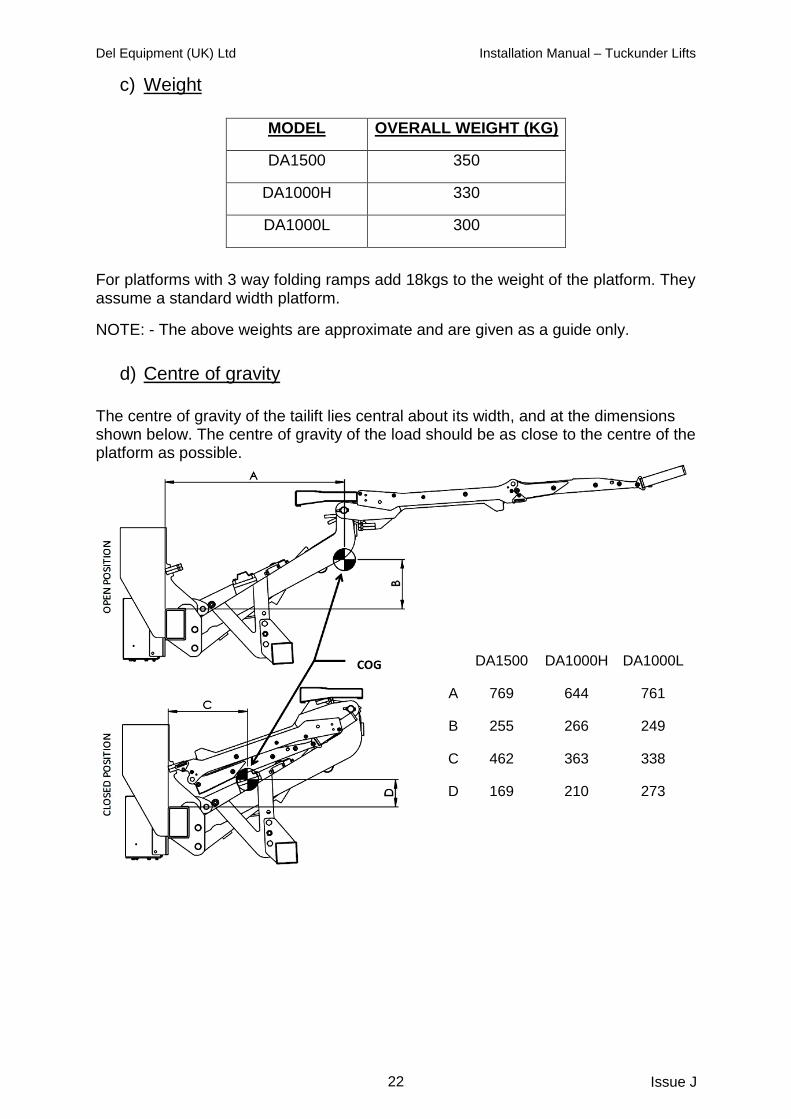
c) Weight
MODEL OVERALL WEIGHT (KG)
DA1500 350
DA1000H 330
DA1000L 300
For platforms with 3 way folding ramps add 18kgs to the weight of the platform. They assume a standard width platform.
NOTE: - The above weights are approximate and are given as a guide only.
d) Centre of gravity
The centre of gravity of the tailift lies central about its width, and at the dimensions shown below. The centre of gravity of the load should be as close to the centre of the platform as possible.
DA1500 DA1000H DA1000L
A 769 644 761
B 255 266 249
C 462 363 338
D 169 210 273

Del Equipment (UK) Ltd Installation Manual – Tuckunder Lifts
23 Issue J
9. FINAL INSPECTION CHECKLIST
Installation is not fully complete until all the following items are checked and verified and the Installation Manual is passed on to the end user of the lift.
Reservoir is full of oil with platform fully lowered. All tack welds are now complete welds. Platform meets the bed height. Hydraulic components checked for leakage. Battery cables attached and clamped tight. Lights wired properly and are operational. Vehicle licence plate properly fitted. All decals properly in place and legible after painting. Operators and Installation manual in vehicle. Pivots greased if needed. Platform opens properly. Control switch operates properly. Platform spring assistance working.
Tailift tested and certificate issued.
SAFETY
!
CAUTION: Do not use tailift if any of the items below are not checked and verified. If you have any questions contact DEL sales. Failure to verify the following could result in severe damage to the tailift or personal injury.

Del Equipment (UK) Ltd Installation Manual – Tuckunder Lifts
24 Issue J
10. WIRING DIAGRAM

Del Equipment (UK) Ltd Installation Manual – Tuckunder Lifts
25 Issue J
11. HYDRAULIC DIAGRAM

Del Equipment (UK) Ltd Installation Manual – Tuckunder Lifts
26 Issue J
DEL
DEL WARRANTY REGISTRATION FORM
REGISTER YOUR DEL TAILIFT AND OBTAIN UPDATED
INFORMATION ON THE DEL RANGE
PLEASE PRINT CLEARLY.
1. Purchasers name: 2. Address:
Town: County: Postcode: Tel No:
3. Form completed by: Position: 4. Type of business: 5. Model purchased: Serial No: 6. Truck make/model/reg. 7. Date purchased: 8. Purchased from: 9. Lift installed by: 10. Were you satisfied with the installation of this unit? 11. Were all warning decals affixed to the tailift? 12. Number of tailifts you now operate?
Of these, how many are DEL units? What other makes of tailift do you own?
13. Was this purchase a replacement? 14. Why did you select a DEL tailift?
Owned a DEL unit previously
Dealer recommended it
Colleague recommended it
Advertisement (Name of magazine)
Received literature in post
Price
Other (Please specify) 15. Are you planning to buy additional lifts within the next six months?
Thank you for completing this registration form. Once completed please return the form to DEL Equipment (U.K.) Ltd at the address above.
DEL EQUIPMENT (U.K.) LTD Building 1, Windrush Park Road
Windrush Industrial Park, Witney Oxon, OX29-7HA
TEL: 01993 708811 FAX: 01993 708787
EMAIL: [email protected] WEBSITE: www.del-uk.com

Del Equipment (UK) Ltd Installation Manual – Tuckunder Lifts
27 Issue J
DEL
LIFT TEST CERTIFICATE
DATE: DD / MM / YYYY
CUSTOMER NAME: INSTALLER/TESTER NAME:
ADDRESS:
ADDRESS:
MODEL:
FITTED TO:
SERIAL NO:
VEHICLE REG:
RATED CAPACITY: kg (TEST LOAD)
OVERLOAD SETTING: kg (TEST LOAD+25%)
INSTALLATION TESTS 1. STATIC TEST: PASS / FAIL
2. DYNAMIC TEST: PASS / FAIL 3. EXCESSIVE LOAD TEST: PASS / FAIL
4. SAFETY FUNCTION: PASS / FAIL 5. VERTICAL SPEED TEST: PASS / FAIL
HAS THE FINAL INSPECTION CHECKLIST BEEN COMPLETED YES / NO
HAS THE OPERATORS MANUAL BEEN PASSED ON TO THE END-USER YES / NO
GENERAL OBSERVATIONS:
We certify that the product detailed above has been installed in accordance with the manufacturer’s instructions and that all post installation tests have been completed and passed. We confirm that the manufacturer and end user have been consulted with regard to the products compatibility with the vehicle taking into account the intended use. The product has not been modified in any way. Any modifications have been approved in writing by the manufacturer.
TESTED BY:
SIGNED:
COMPANY:
THIS CERTIFICATE SHOULD REMAIN IN THE INSTALLATION HANDBOOK AND A
COPY MADE TO BE RETURNED OR FAXED TO DEL EQUIPMENT (UK) LTD.
DEL EQUIPMENT (U.K.) LTD Building 1, Windrush Park Road
Windrush Industrial Park, Witney Oxon, OX29-7HA
TEL: 01993 708811 FAX: 01993 708787
EMAIL: [email protected] WEBSITE: www.del-uk.com

Del Equipment (UK) Ltd Installation Manual – Tuckunder Lifts
28 Issue J