delay analysis of push to -talk over cellular …€¦ · · 2016-07-01are done by dividing into...
TRANSCRIPT

Delay analysis of PoC service solutions for Public Safety communications over LTE networks
1/48
DELAY ANALYSIS OF PUSH-TO-TALK OVER CELLULAR (POC) SERVICE SOLUTIONS FOR PUBLIC SAFETY
COMMUNICATIONS OVER LTE NETWORKS
Author: Chengsui Lu
Date: 27 August, 2012
Abstract – In this master thesis, the concept of public safety communication solutions over modern commercial cellular systems is presented, and the delay analysis for Puch-to-Talk over Cellular (PoC) service is provided especially for the LTE and IMS networks. Firstly, the motivations and requirements of public safety communications using commercial cellular technology are studied and introduced. Secondly, the 3GPP IMS-based public safety communication network architecture and the PoC service are described in details. Thirdly, we make a survey of the PoC delay targets for modern emergency communication networks. Finally, the call set-up delay and end to end delay calculations are done by dividing into latency components of each network entities. Our analysis shows that typical call set-up time and end to end delay are within 275 milliseconds and 250 milliseconds respectively, and the mainstream LTE cellular technology can be designed to satisfy the stringent time constraints for public safety purpose, making LTE a promising option for public safety communications.
Key words: Public Safety communication networks; delay analysis; LTE; call setup time; end to end latency; IMS.
Delay analysis of PoC service solutions for Public Safety communications over LTE networks
2/48
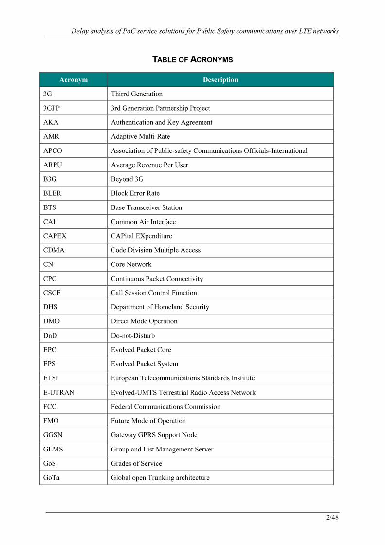
TABLE OF ACRONYMS
Acronym Description
3G Thirrd Generation
3GPP 3rd Generation Partnership Project
AKA Authentication and Key Agreement
AMR Adaptive Multi-Rate
APCO Association of Public-safety Communications Officials-International
ARPU Average Revenue Per User
B3G Beyond 3G
BLER Block Error Rate
BTS Base Transceiver Station
CAI Common Air Interface
CAPEX CAPital EXpenditure
CDMA Code Division Multiple Access
CN Core Network
CPC Continuous Packet Connectivity
CSCF Call Session Control Function
DHS Department of Homeland Security
DMO Direct Mode Operation
DnD Do-not-Disturb
EPC Evolved Packet Core
EPS Evolved Packet System
ETSI European Telecommunications Standards Institute
E-UTRAN Evolved-UMTS Terrestrial Radio Access Network
FCC Federal Communications Commission
FMO Future Mode of Operation
GGSN Gateway GPRS Support Node
GLMS Group and List Management Server
GoS Grades of Service
GoTa Global open Trunking architecture
Delay analysis of PoC service solutions for Public Safety communications over LTE networks
3/48
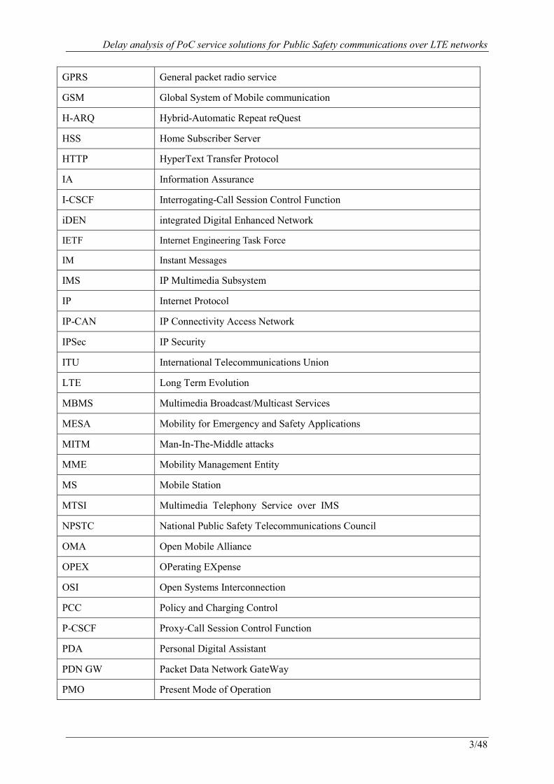
GPRS General packet radio service
GSM Global System of Mobile communication
H-ARQ Hybrid-Automatic Repeat reQuest
HSS Home Subscriber Server
HTTP HyperText Transfer Protocol
IA Information Assurance
I-CSCF Interrogating-Call Session Control Function
iDEN integrated Digital Enhanced Network
IETF Internet Engineering Task Force
IM Instant Messages
IMS IP Multimedia Subsystem
IP Internet Protocol
IP-CAN IP Connectivity Access Network
IPSec IP Security
ITU International Telecommunications Union
LTE Long Term Evolution
MBMS Multimedia Broadcast/Multicast Services
MESA Mobility for Emergency and Safety Applications
MITM Man-In-The-Middle attacks
MME Mobility Management Entity
MS Mobile Station
MTSI Multimedia Telephony Service over IMS
NPSTC National Public Safety Telecommunications Council
OMA Open Mobile Alliance
OPEX OPerating EXpense
OSI Open Systems Interconnection
PCC Policy and Charging Control
P-CSCF Proxy-Call Session Control Function
PDA Personal Digital Assistant
PDN GW Packet Data Network GateWay
PMO Present Mode of Operation
Delay analysis of PoC service solutions for Public Safety communications over LTE networks
4/48
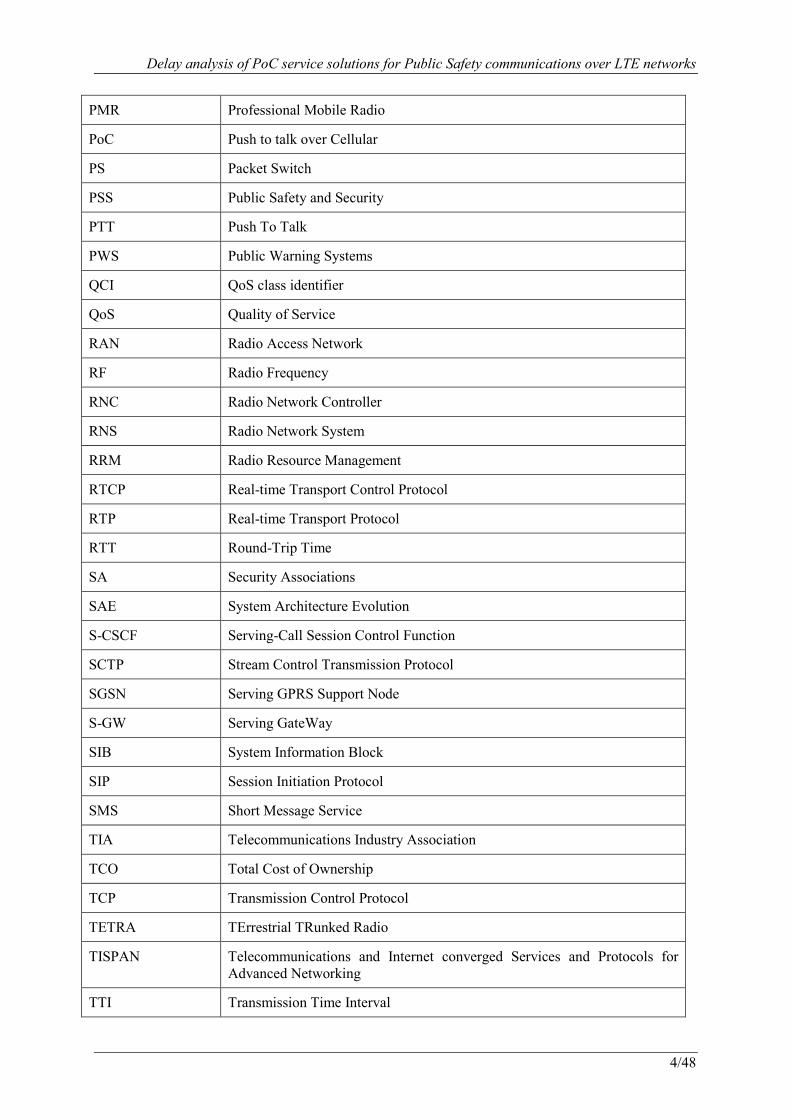
PMR Professional Mobile Radio
PoC Push to talk over Cellular
PS Packet Switch
PSS Public Safety and Security
PTT Push To Talk
PWS Public Warning Systems
QCI QoS class identifier
QoS Quality of Service
RAN Radio Access Network
RF Radio Frequency
RNC Radio Network Controller
RNS Radio Network System
RRM Radio Resource Management
RTCP Real-time Transport Control Protocol
RTP Real-time Transport Protocol
RTT Round-Trip Time
SA Security Associations
SAE System Architecture Evolution
S-CSCF Serving-Call Session Control Function
SCTP Stream Control Transmission Protocol
SGSN Serving GPRS Support Node
S-GW Serving GateWay
SIB System Information Block
SIP Session Initiation Protocol
SMS Short Message Service
TIA Telecommunications Industry Association
TCO Total Cost of Ownership
TCP Transmission Control Protocol
TETRA TErrestrial TRunked Radio
TISPAN Telecommunications and Internet converged Services and Protocols for Advanced Networking
TTI Transmission Time Interval

Delay analysis of PoC service solutions for Public Safety communications over LTE networks
5/48
UDP User Datagram Protocol
UE User Equipment
UHF Ultra High Frequency
UMTS Universal Mobile Telecommunications System
UPSF User Profile Server Function
UTRAN UMTS Terrestrial Radio Access Network
VHF Very High Frequency
VoIP Voice over IP
WiFi Wireless Fidelity
XDMS XML Document Management Server
XML eXtensible Markup Language

Delay analysis of PoC service solutions for Public Safety communications over LTE networks
6/48
TABLE OF CONTENTS
1. INTRODUCTION ................................................................................................................................. 10
1.1 TECHNOLOGICAL TRENDS IN PUBLIC SAFETY COMMUNICATION NETWORKS ................................ 10
1.2 KEY BENEFITS OF ADOPTING MAINSTREAM CELLULAR TECHNOLOGY ............................................ 11
1.3 CHALLENGES AND OPPORTUNITIES ................................................................................................. 12
1.4 OBJECTIVES ..................................................................................................................................... 12
1.5 RELATED WORKS ............................................................................................................................. 13
1.6 THESIS OUTLINE ............................................................................................................................... 13
2. TECHNICAL REQUIREMENTS ........................................................................................................... 14
2.1 GENERAL REQUIREMENTS ............................................................................................................... 14
2.1.1 Basic and specialized services .............................................................................................. 14
2.1.2 Network availability ............................................................................................................. 15
2.1.3 Coverage ............................................................................................................................... 15
2.1.4 Capacity ................................................................................................................................ 15
2.1.5 Interoperability ..................................................................................................................... 15
2.1.6 Secure scheme ...................................................................................................................... 15
2.1.7 Call setup time ...................................................................................................................... 15
2.1.8 Voice quality ........................................................................................................................ 15
2.2 POC OVER LTE REQUIREMENTS ...................................................................................................... 16
3. IMS-BASED PUBLIC SAFETY COMMUNICATION NETWORK SOLUTION ....................................... 17
3.1 OVERVIEW: IMS CORE AND 3GPP IP-CAN .................................................................................... 17
3.2 FUNCTIONAL ENTITIES ..................................................................................................................... 18
3.2.1 IM Subsystem ....................................................................................................................... 18
3.2.2 IP Connectivity Access Network (IP-CAN) ......................................................................... 18
3.3 IMS APPLICATIONS ......................................................................................................................... 19
3.3.1 PoC services ......................................................................................................................... 20
3.3.2 PoC architecture ................................................................................................................... 20
3.3.3 PoC protocols ....................................................................................................................... 21
3.3.4 PoC procedures..................................................................................................................... 21
4. DELAY ANALYSIS ............................................................................................................................. 24
4.1 POC DELAY TARGETS ...................................................................................................................... 24
4.1.1 Delay targets in commercial mobile networks ..................................................................... 24
4.1.2 Delay targets for public safety communication networks .................................................... 27
4.2 POC DELAY ASSUMPTIONS .............................................................................................................. 28
4.3 POC DELAY CALCULATIONS ............................................................................................................ 28

Delay analysis of PoC service solutions for Public Safety communications over LTE networks
7/48
4.3.1 Delay components in EPS (E-UTRAN and EPC) ................................................................ 29
4.3.2 Delay components in IMS and Application layer ................................................................ 32
4.3.3 Latencies in session establishment ....................................................................................... 32
4.3.4 Floor control latencies .......................................................................................................... 36
4.3.5 End to end latencies .............................................................................................................. 37
4.3.6 Delays between different IMS cores .................................................................................... 40
4.3.7 Sensitivity analysis ............................................................................................................... 41
4.3.8 Conclusions .......................................................................................................................... 44
5. CONCLUSION .................................................................................................................................... 45
6. REFERENCES..................................................................................................................................... 46

Delay analysis of PoC service solutions for Public Safety communications over LTE networks
8/48
LIST OF FIGURES
Figure 1.1: Technological trends of Public Safety Communication Networks in initial stage ............. 11
Figure 1.2: Technological trends of Public Safety Communication Networks in future stage ............. 11
Figure 2.1: Technological requirements of PoC over LTE for public safety ........................................ 16
Figure 3.1: Architecture of the IMS-based Public Safety Communication Network ............................ 17
Figure 3.2: PoC service architecture (figure with modifications based on [30]) .................................. 20
Figure 3.3: PoC protocol stack .............................................................................................................. 21
Figure 3.4: PoC emergency call scenario .............................................................................................. 22
Figure 3.5: PoC instant group talk procedure ........................................................................................ 23
Figure 4.1: PoC early media session establishment procedure ............................................................. 25
Figure 4.2: PoC late media session establishment procedure ................................................................ 26
Figure 4.3: PoC “Right to speak” and “Start to speak” ......................................................................... 26
Figure 4.4: The analytic model for PoC delay calculation .................................................................... 28
Figure 4.5: Control plane latency from idle to connected mode [50].................................................... 29
Figure 4.6: Paging procedures ............................................................................................................... 30
Figure 4.7: User-plane latency .............................................................................................................. 31
Figure 4.8: Session establishment (early media) delay analysis ........................................................... 33
Figure 4.9: Session establishment (late media) delay analysis .............................................................. 34
Figure 4.10: Group session establishment (early media) delay analysis ............................................... 35
Figure 4.11: Main delay components in session establishments ........................................................... 36
Figure 4.12: Floor changeover delay analysis ....................................................................................... 37
Figure 4.13: End to end delay analysis .................................................................................................. 37
Figure 4.14: Mouth to ear delay analysis .............................................................................................. 38
Figure 4.15: Turnaround Time analysis ................................................................................................ 39
Figure 4.16: Session establishment (early media) between different IMS cores .................................. 40
Figure 4.17: Sensitivity analysis on the LTE user plane latency .......................................................... 42
Figure 4.18: Sensitivity analysis on the radio C-plane latencies ........................................................... 43
Figure 4.19: Sensitivity analysis on the IMS/Server/Client processing latency .................................... 44
Delay analysis of PoC service solutions for Public Safety communications over LTE networks
9/48
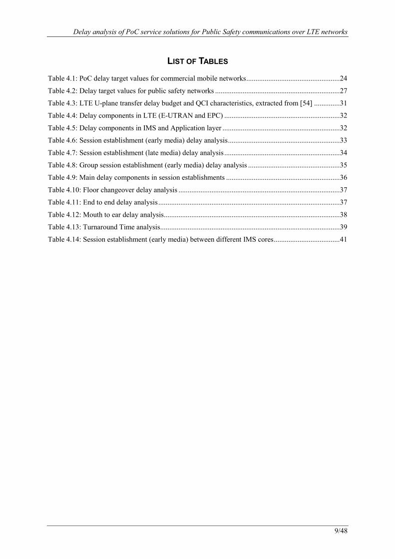
LIST OF TABLES
Table 4.1: PoC delay target values for commercial mobile networks ................................................... 24
Table 4.2: Delay target values for public safety networks .................................................................... 27
Table 4.3: LTE U-plane transfer delay budget and QCI characteristics, extracted from [54] .............. 31
Table 4.4: Delay components in LTE (E-UTRAN and EPC) ............................................................... 32
Table 4.5: Delay components in IMS and Application layer ................................................................ 32
Table 4.6: Session establishment (early media) delay analysis ............................................................. 33
Table 4.7: Session establishment (late media) delay analysis ............................................................... 34
Table 4.8: Group session establishment (early media) delay analysis .................................................. 35
Table 4.9: Main delay components in session establishments .............................................................. 36
Table 4.10: Floor changeover delay analysis ........................................................................................ 37
Table 4.11: End to end delay analysis ................................................................................................... 37
Table 4.12: Mouth to ear delay analysis ................................................................................................ 38
Table 4.13: Turnaround Time analysis .................................................................................................. 39
Table 4.14: Session establishment (early media) between different IMS cores .................................... 41
Delay analysis of PoC service solutions for Public Safety communications over LTE networks
10/48
1. Introduction
1.1 Technological trends in Public Safety Communication Networks
Public Safety and Security (PSS) services, including fire brigades, police forces, ambulance services, coastguards, etcetera, are a prior subject for citizens and governments. Well functioning communication solutions are an essential element for these public safety agencies to coordinate resources with their command centers as well as other PSS users in the field both during daily routine work and in emergencies.
Experience has proven that the mandatory services and facilities required by public safety organizations can only be partially provided on existing commercial communications systems, which even often crash under the burden when catastrophe strikes. Therefore, many agencies and the governments have been investing significant resources in building and funding reliable first responder communication networks to be better prepared. Traditionally public safety entities depend on the analog Professional Mobile Radio (PMR) systems, that use radio-broadcast techniques from short wave to Very High Frequency (VHF), Ultra High Frequency (UHF) and microwave for basic group communication. These systems often only focus on voice communication, and are found to be incapable to keep pace with increasing demands of new features and services, such as transmitting fingerprints and videos of crime scenes. Moreover, the legacy analogue PMR networks have the issue of interoperability as identified in several studies [1],[2] from USA Department of Homeland Security (DHS), because of the incompatibility among agencies, vendors and techniques. In a large fire or disaster, different public safety sectors may be forced to use hand signals or delivering messages as the old Greeks would, on foot. Today many public safety networks evolve to sophisticated digital PMR systems, for example TErrestrial TRunked Radio (TETRA) [3], Association of Public-Safety Communications Officials-International Project 25 (APCO P25) [4], TETRAPOL [5], integrated Digital Enhanced Network (iDEN) [6], Global open Trunking architecture (GoTa) [7], etc. Digital technology helps to improve the quality and security of communication, however, the main drawback of this approach is that, the relatively small and closed market leads to far too high capital and operational expenditure, and short on advanced functionalities due to the increasing complexity of
public safety tasks to face nature disasters and terrorist attacks [8]�[9], for instance, surveillance video and high-speed data transfers.
Modern commercial cellular networks has witnessed an explosive growth of high spectrum efficiency, reduced latency, and improved prioritization of users. As a consequence, currently mobile communication systems have in the past few years been revisited as an option for public safety organizations in many countries to reduce the cost per subscriber and allow improved services [10]-[15]. Unfortunately, earlier studies [13][14] conclude that the fundamental requirements of low delays and high system capacity for mission critical communities are not met in Universal Mobile Telecommunications System (UMTS) networks. Following the mainstream technology developments of the consumer market, most of the difficulties for public safety communication networks are foreseen to be sorted out in the infrastructure of 3rd Generation Partnership Project (3GPP) Internet Protocol (IP) Multimedia Subsystem (IMS) [16] on top of 3G (Third Generation) / Beyond 3G (B3G) Radio Access Network (RAN). Furthermore, the Federal Communications Commission (FCC) in USA has already launched proceedings on the congressionally mandated National Broadband Plan since 2010, adopting 3G/B3G technologies to boost capabilities for commercial consumers and homeland securities. Recently, National Public Safety Telecommunications Council (NPSTC) [17] in USA provided a starting point from the definition and requirements to support mission critical voice with the latest B3G wireless technology of Long Term Evolution (LTE) [18].
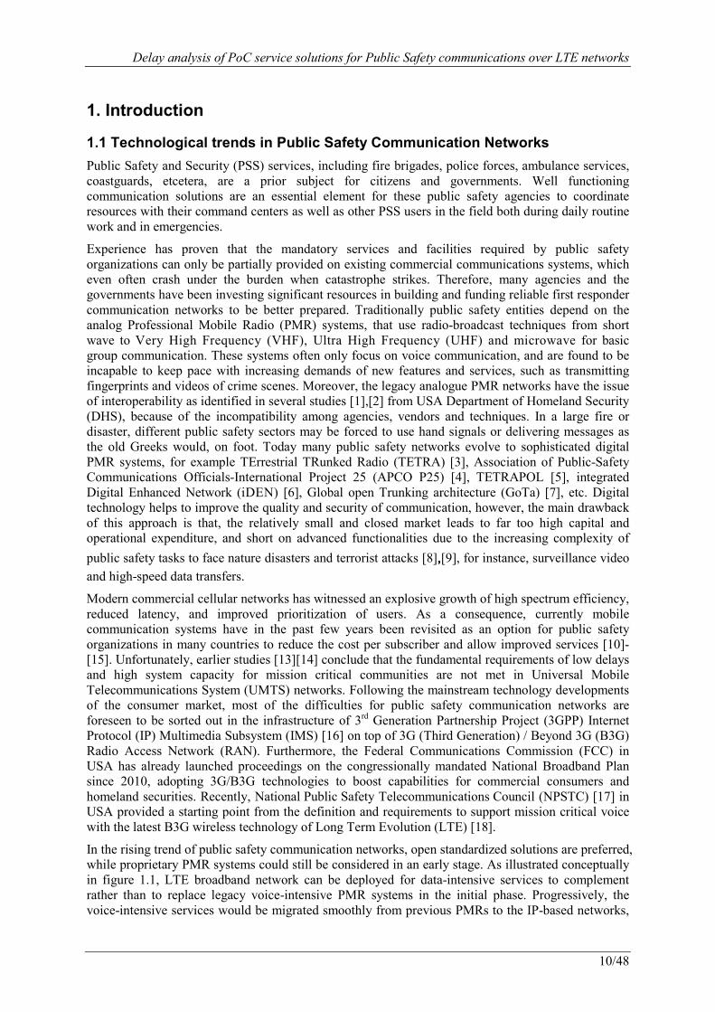
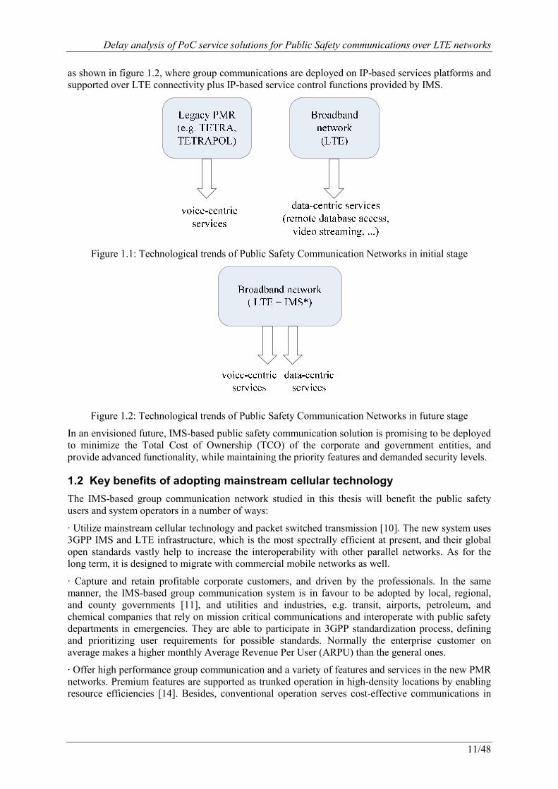
In the rising trend of public safety communication networks, open standardized solutions are preferred, while proprietary PMR systems could still be considered in an early stage. As illustrated conceptually in figure 1.1, LTE broadband network can be deployed for data-intensive services to complement rather than to replace legacy voice-intensive PMR systems in the initial phase. Progressively, the voice-intensive services would be migrated smoothly from previous PMRs to the IP-based networks,
Delay analysis of PoC service solutions for Public Safety communications over LTE networks
11/48
as shown in figure 1.2, where group communications are deployed on IP-based services platforms and supported over LTE connectivity plus IP-based service control functions provided by IMS.
Figure 1.1: Technological trends of Public Safety Communication Networks in initial stage
Figure 1.2: Technological trends of Public Safety Communication Networks in future stage
In an envisioned future, IMS-based public safety communication solution is promising to be deployed to minimize the Total Cost of Ownership (TCO) of the corporate and government entities, and provide advanced functionality, while maintaining the priority features and demanded security levels.
1.2 Key benefits of adopting mainstream cellular technology
The IMS-based group communication network studied in this thesis will benefit the public safety users and system operators in a number of ways:
· Utilize mainstream cellular technology and packet switched transmission [10]. The new system uses 3GPP IMS and LTE infrastructure, which is the most spectrally efficient at present, and their global open standards vastly help to increase the interoperability with other parallel networks. As for the long term, it is designed to migrate with commercial mobile networks as well.
· Capture and retain profitable corporate customers, and driven by the professionals. In the same manner, the IMS-based group communication system is in favour to be adopted by local, regional, and county governments [11], and utilities and industries, e.g. transit, airports, petroleum, and chemical companies that rely on mission critical communications and interoperate with public safety departments in emergencies. They are able to participate in 3GPP standardization process, defining and prioritizing user requirements for possible standards. Normally the enterprise customer on average makes a higher monthly Average Revenue Per User (ARPU) than the general ones.
· Offer high performance group communication and a variety of features and services in the new PMR networks. Premium features are supported as trunked operation in high-density locations by enabling resource efficiencies [14]. Besides, conventional operation serves cost-effective communications in
Delay analysis of PoC service solutions for Public Safety communications over LTE networks
12/48
low-density and routine cases. Communications could be in clear form or secured with encryption, key management, and mutual authentication.
· Capitalize on the complete set of investments of edge and core applications already made. On one hand, modern commercial wireless networks have the key assets, i.e. network, spectrum and back-office, to deliver the IMS-based group radio solution. On the other hand, it provides Common Air Interfaces (CAI) to be compatible and coexist with legacy PMR networks [11]. Hence the proposed system offers an excellent way to make use of these resources and efforts to meet public safety users.
· Leverage a combined strength of cellular and PMR vendors. 70 years of private group radio’s experience and over one hundred years’ development of commercial equipment manufacturers and service providers in the marketplace add to a large portfolio of products and competitions, which continue to enhance technology evolution and innovation.
1.3 Challenges and opportunities
Correspondingly, the next generation public safety communication networks have the following challenges to overcome:
(1) Service availability. As the most important point, it is a critical task for the civil wireless infrastructure to ensure a high level of “five nines”, that is 99.999% probability of Quality of Service (QoS), service continuation and network reliability, which is consisted of equipment failure, equipment redundancy, bandwidth reservation, network segmentation and bandwidth optimization. (2) Mobility of forces [14]. When the public safety personnel quickly move to a new mission site, fluctuating communication load must be supported as for the whole perspective. (3) Advanced services. Increasingly sophisticated functionality should be provided [11], e.g. call pre-emption, group video calls, Public Warning Systems (PWS), data collaboration (share maps or tactical data), and the network is supposed to easily integrate new and evolving services. (4) Network security. Due to the sensitive nature of government and defence communications, specific layer of Information Assurance (IA) is strictly stipulated to be integrated [10], with respect to availability, integrity, authentication, confidentiality, and non-repudiation. (5) Smooth updating. Particular public safety segments need the flexibility to keep the existing PMR systems and choose its own technology and economic phase to migrate from Present Mode of Operation (PMO) to Future Mode of Operation (FMO).
In addition to the newly proposed IMS-based group radio technology itself, the external market presents unprecedented opportunities at the threshold of this new era:
· Save PMR network cost of ownership [10], [15]. Public safety officials are looking for ways to take place of the rising CAPital EXpenditure (CAPEX) and OPerating EXpense (OPEX) to maintain its trunked system, especially in the current financial climate.
· Take advantage of the evolutionary power of cellular technology, which turns to be a hot topic in today’s wireless consumer market, and is future proved with continuous improvements of features and services [11], [14].
· Exploit the development of handset diversity. Commercial portable devices already supply a wide variety of data applications with user friendly interfaces, and directly support the advanced services for public safety forces.
1.4 Objectives
The objective of this thesis is to analyze the feasibility of applying IMS-based mobile broadband networks to provide tactical group voice services for public safety purpose. More specifically, we contribute to:
· outline the concept of IMS-based public safety communication network using commercial cellular technology, and describe its Push To Talk (PTT) over Cellular (PoC) solution;
· evaluate the performance of the PoC over 3G/B3G RANs, especially on the aspect of the delay requirements analysis of PoC over LTE.
Delay analysis of PoC service solutions for Public Safety communications over LTE networks
13/48
1.5 Related works
For 2G telecommunications, TETRA Association analyzed the potential of GPRS and Code Division Multiple Access (CDMA) networks for mission critical use [13]. They can support cost effective radio coverage for digital services in densely populated areas. But 2G technologies have the problem of 100% rural area coverage, none Direct Mode Operation (DMO) or base station fallback for network outages, slow set up time of VoIP protocols, lack of efficient priority and pre-emptive mechanisms. The study concludes that commercial networks have not been yet considered being properly able to serve the law enforcement user segments by that time.
Afterwards, IMS-based PoC service on top of GPRS system for public safety purpose is further scrutinized [14]. This solution still has difficulties to fulfill the needs about call set up time, priority and pre-emptive options. Nevertheless, it provides sufficient performance in the advanced aspects of data/video applications, group call functionality, roaming, interoperability, and user friendliness. With minor modification, some requirements of coverage, voice quality, operation continuity, network resilience, security and privacy may meet the acceptable level. Moreover, it is observed that most of the challenges are caused by the GPRS access network. This study already points out, by means of proper radio network dimensioning and network upgrades, that IMS-based PoC over commercial mobile systems could become a good alternative to the legacy analogue PMR network.
In 3G and B3G times, IMS PoC with UMTS / CDMA2000 [11], [19] and HSPA / LTE [10], [15] come with premium features and higher performances than before. Low latency, extended coverage, talk around supports, scalable architecture, well developed priority and pre-emptive schemes are achieved to solve the remaining issues from previous cellular networks. Moreover, novel concepts such as link adaptation and MBMS (Multimedia Broadcast/Multicast Services) are introduced to improve the system capacity. [15] examines the capacity limit of a LTE network, and optimizes the speech codec to further increase its capacity. Therefore, the new generation of commercial cellular network turns to be a milestone which can be expected to be competent for public safety communications, and the last 3G transitional technique of LTE may provide even better quality than the basic requirements as discussed in the Chapter 2.
In the mean time, 3GPP opens a new work item [20]� [21] to study fundamental user requirements for public safety purpose considering inputs from NPSTC, TETRA, P25, etc, and ETSI has already finished a technical specification of functional requirements for emergency communications [22]. LTE is foreseen to be a strong candidate for implementation, but at the moment lacks some features such as direct mode services and efficient group communications, which is going to be covered in its Release 12 in the near future. Potential solutions can be native LTE or Over-The-Top application (e.g. PoC) [23]. Nevertheless, the critical aspect of PoC call set up time over LTE and end to end latency still need to be scrutinized carefully. Furthermore, as showed in one of the industry reports, up to 39% of mobile calls in current commercial use fall below the minimum design targets of 3GPP standards [24]. Hence, some adaptation and tunings in 3G / B3G networks are still necessary to exploit the full potential to serve for the public safety use.
1.6 Thesis outline
The remainder of this thesis is organized as follows. Chapter 2 investigates the general requirements to be achieved for public safety users to protect and preserve life and property, and analyzes the critical requirements especially for the implementation of PoC service over LTE networks for public safety purpose. Chapter 3 presents the public safety communication solution over the mainstream cellular technology and packet switched transmission platform, including the system architecture, network entities, the PoC service and its procedures. Chapter 4 firstly makes a survey of delay target recommendations, and then provides an analytical analysis for the delays of IMS-based PoC service via LTE networks following the analytic model derived from the methodology from ITU-T. Some improvement proposals are given to get better performance of the service. Finally, Chapter 5 concludes the thesis.
Delay analysis of PoC service solutions for Public Safety communications over LTE networks
14/48
2. Technical Requirements In accordance with their objectives, first responders demand high performance, special functional, robust and versatile communications among individual units, groups and command and control centres. In the following, the mandatory technique requirements of IMS-based public safety communication systems are discussed in details, beginning from a general point of view and reach the conclusions for LTE and IMS networks.
2.1 General requirements
2.1.1 Basic and specialized services
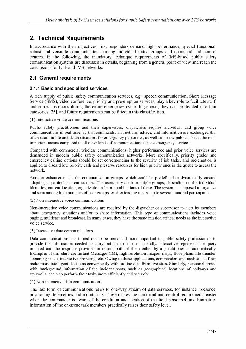
A rich supply of public safety communication services, e.g., speech communication, Short Message Service (SMS), video conference, priority and pre-emption services, play a key role to facilitate swift and correct reactions during the entire emergency cycle. In general, they can be divided into four categories [25], and future requirements can be fitted in this classification.
(1) Interactive voice communications
Public safety practitioners and their supervisors, dispatchers require individual and group voice communications in real time, so that commands, instructions, advice, and information are exchanged that often result in life and death situations for emergency personnel, as well as for the public. This is the most important means compared to all other kinds of communications for the emergency services.
Compared with commercial wireless communications, higher performance and prior voice services are demanded in modern public safety communication networks. More specifically, priority grades and emergency calling options should be set corresponding to the severity of job tasks, and pre-emption is applied to discard low priority calls and preserve resources for high priority ones in the queue to access the network.
Another enhancement is the communication groups, which could be predefined or dynamically created adapting to particular circumstances. The users may act in multiple groups, depending on the individual identities, current location, organization role or combinations of these. The system is supposed to organize and scan among high numbers of user groups, each extending in size up to several hundred participants.
(2) Non-interactive voice communications
Non-interactive voice communications are required by the dispatcher or supervisor to alert its members about emergency situations and/or to share information. This type of communications includes voice paging, multicast and broadcast. In many cases, they have the same mission critical needs as the interactive voice service.
(3) Interactive data communications
Data communications has turned out to be more and more important to public safety professionals to provide the information needed to carry out their missions. Literally, interactive represents the query initiated and the response provided in return, both of them either by a practitioner or automatically. Examples of this class are Instant Messages (IM), high resolution images, maps, floor plans, file transfer, streaming video, interactive browsing, etc. Owing to these applications, commanders and medical staff can make more intelligent decisions conveniently with on-line data from live sites. Similarly, personnel armed with background information of the incident spots, such as geographical locations of hallways and stairwells, can also perform their tasks more efficiently and securely.
(4) Non-interactive data communications.
The last form of communications refers to one-way stream of data services, for instance, presence, positioning, telemetries and monitoring. These makes the command and control requirements easier when the commander is aware of the condition and location of the field personnel, and biometrics information of the on-scene task members practically raises their safety level.
Delay analysis of PoC service solutions for Public Safety communications over LTE networks
15/48
Data-intensive multimedia applications have a great potential to improve the efficiency of disaster recovery operations (e.g. real-time access to critical data such as high resolution maps or floor plans, on-field live video transmission from cameras on helmets to a central unit, telemedicine, etc.). A commonly agreed PPDR application catalogue is being elaborated by the Radio Communication Expert Group of the Law Enforcement Working Party (RCEG/LEWP) of the European Council [26] Some of applications included in the catalogue are already in use and most of them are expected to be used in the short or medium term future.
2.1.2 Network availability
In order to keep the state of the network and prevent the system from break down by tiny accidental failures, the maximum resilience with sufficient level of redundancy must be supplied on its own. Various techniques need to be utilized to ensure the network availability. Power backup requires a higher tier than commercial use in case of central power outages during disasters. Distributed systems are designed to tolerate single node failures with little harm to the rest parts. Transmission redundancy, i.e. alternate route options, can relieve traffic peaks within a small area for a short time. In addition, DMO allows mobile terminals to communicate without the network involvement.
2.1.3 Coverage
Expanse network coverage is a fundamental need for public safety systems to provide practical emergency services. Basically, the whole country area should be 100 percents covered even under exceptional conditions, including populated cities, rural areas, mountainous and offshore territories, etc. As a special aspect for emergency communications, there is often a need to provide dedicated carriers for airborne radios e.g. for the helicopters even at distances of hundreds of kilometers from causing interference to ground radios.
2.1.4 Capacity
It is one of the prime requirements to maintain the service availability and prevent subscribers from being congested during busy hours, major or even moderate incidents. Certain technical means are required to be supported by the network, for example, extra capacity reservation, priority and pre-emption based on definite Grades of Service (GoS), simulcast to save half of the resources for group calls.
2.1.5 Interoperability
For the purpose of cooperation, the new communication system must be interoperable with other peer networks and their evolutions, such as the legacy PMR radios.
2.1.6 Secure scheme
Increasing kinds of threats, e.g. passive eavesdropping, active tampering information, replay attacks, Man-In-The-Middle (MITM) attacks, raise severe impact to the feasibility of the proposed network. Minimum security requirements include stronger trust model than commercial environments, mutual authentication between users and networks, air interface encryption, end-to-end encryption and dynamic key management.
2.1.7 Call setup time
The response time for call set up time is an important criterion for public safety networks, since vital calls are always urgent and require instantaneous connections. As a matter of fact, emergency calls on average last for only a few seconds. Typical restrictions for voice call setup time range from 0.3 to 1 second. The most frequently cited number is 500 milliseconds [13].
2.1.8 Voice quality
Voice is so far the primary means of communication for emergency agencies and is treated with the highest regard in the definition of its requirements. It is a premium feature for the public safety

Delay analysis of PoC service solutions for Public Safety communications over LTE networks
16/48
network to provide high voice quality, allowing the listener to identify who is speaking and detect the stress in the speaker’s voice, even with large amounts of background noise.
The above requirements are considered as mandatory baselines for the system to achieve, rather than being partially or inferiorly met. From the former discussion, the modern public safety network must support quality professional services, enhanced resilient and secure attributes, seamless universal coverage, sufficient flexibility, instant actions and cohesive operations, so as to increase the societal protection preparedness and ultimately the ability to handle emergencies.
2.2 PoC over LTE requirements
Considering the above requirements for the implementation of PoC service over LTE networks for public safety purpose, each of them may be related to the connectivity layer of LTE, the service layer of IMS, or both of them. More specifically, basic and specialized communication services are supported on the service layer by the IMS enablers, for instance, PoC enabler, group list management enabler, policy management enabler, and so on. Network availability and coverage are issues of the LTE network deployment, which is out of the scope of our analysis. Capacity has the influence from the LTE network as well as the service layer. On the one hand, it depends on the spectrum efficiency achieved by the transmission technology (e.g., spectrum efficiency, exploitation of multicast/broadcast capabilities, etc.). On the other hand, efficient codecs and a low signaling overhead in the service layer are necessary. Interoperability is considered both among various standardized radio access technologies and diverse service platforms over the IP-based open architecture to support the seamless communication among public safety segments. Secure schemes should be provided from air interfaces of the physic layer to security protocols and privacy services on the application layer in the whole system. Call set up time and voice quality deal with all the relative network functionalities on the connectivity and the service layers, especially the call set up time will be analyzed in the remaining part of the thesis.
Service layer( IMS + Platforms )
Connectivity layer( LTE network )
Basic and specialized services
Network availability
Coverage
Capacity
Interoperability
Security
Call setup time
Voice quality
Figure 2.1: Technological requirements of PoC over LTE for public safety
Delay analysis of PoC service solutions for Public Safety communications over LTE networks
17/48
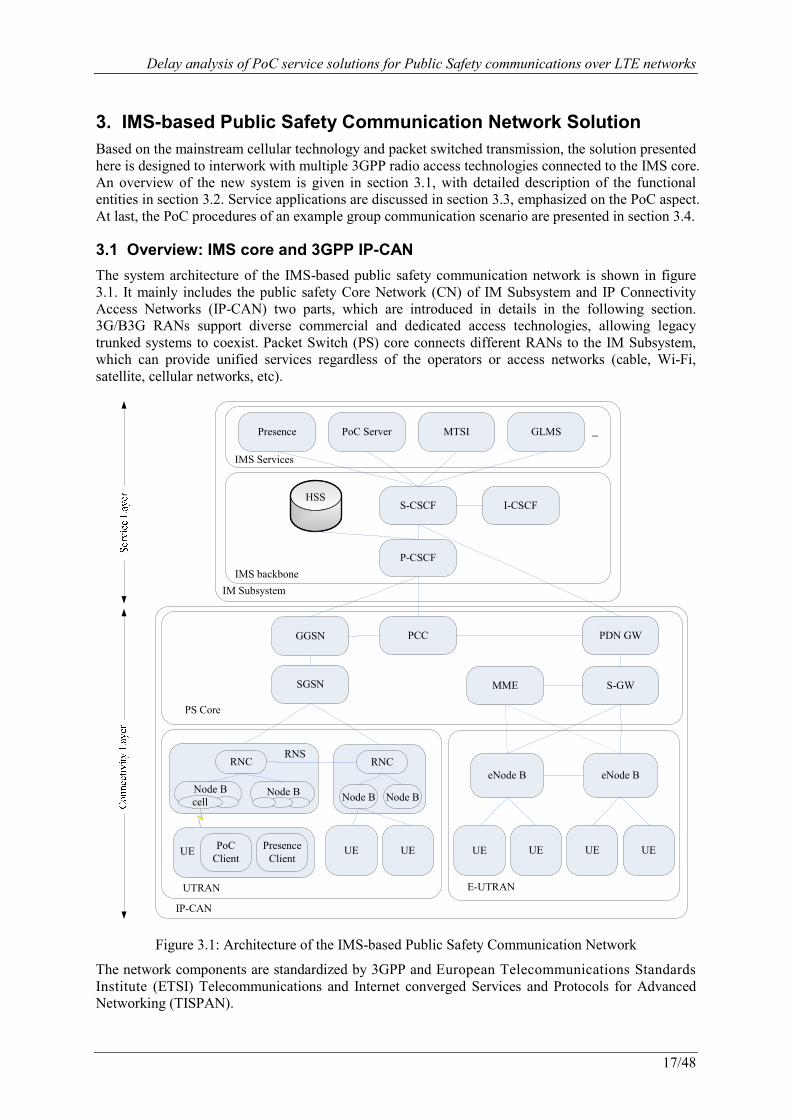
3. IMS-based Public Safety Communication Network Solution Based on the mainstream cellular technology and packet switched transmission, the solution presented here is designed to interwork with multiple 3GPP radio access technologies connected to the IMS core. An overview of the new system is given in section 3.1, with detailed description of the functional entities in section 3.2. Service applications are discussed in section 3.3, emphasized on the PoC aspect. At last, the PoC procedures of an example group communication scenario are presented in section 3.4.
3.1 Overview: IMS core and 3GPP IP-CAN
The system architecture of the IMS-based public safety communication network is shown in figure 3.1. It mainly includes the public safety Core Network (CN) of IM Subsystem and IP Connectivity Access Networks (IP-CAN) two parts, which are introduced in details in the following section. 3G/B3G RANs support diverse commercial and dedicated access technologies, allowing legacy trunked systems to coexist. Packet Switch (PS) core connects different RANs to the IM Subsystem, which can provide unified services regardless of the operators or access networks (cable, Wi-Fi, satellite, cellular networks, etc).
S-CSCFHSS
I-CSCF
P-CSCF
Presence PoC Server MTSI GLMS …
IMS backbone
IMS Services
GGSN PCC PDN GW
PS Core
S-GWSGSN
PoC Client
PresenceClient
UE
RNCRNS
Node B
UE UE
UTRAN E-UTRAN
eNode B
UE UE
RNC
Node B Node B
eNode B
UE UE
cellNode B
MME
IM Subsystem
IP-CAN
Figure 3.1: Architecture of the IMS-based Public Safety Communication Network
The network components are standardized by 3GPP and European Telecommunications Standards Institute (ETSI) Telecommunications and Internet converged Services and Protocols for Advanced Networking (TISPAN).

Delay analysis of PoC service solutions for Public Safety communications over LTE networks
18/48
3.2 Functional entities
3.2.1 IM Subsystem
IMS is a global, access-independent and standard-based IP connectivity and service control architecture [16] that enables various types of multimedia services, especially PoC applications to public safety end-users using common Internet-based protocols. The main network components are:
· Proxy-Call Session Control Function (P-CSCF)
P-CSCF is the first contact point to the IM CN subsystem. P-CSCF compresses Session Initiation Protocol (SIP) [27] messages, maintains Security Associations (SA) according to IP Security (IPSec) protocol, interacts with Policy and Charging Rules Function (PCRF), and detects emergency session.
· Serving-Call Session Control Function (S-CSCF)
S-CSCF actually handles the session states in the network, and is the focal node of the signalling plane. It is responsible for the tasks of handling registration procedures, making routing decisions, maintaining session states and storing the service profiles.
· Interrogating -Call Session Control Function (I-CSCF)
I-CSCF locates at the edge of an administrative domain. It is the contact point within an operator's network for all connections destined to a user of that network. This functionality inquires the next hop S-CSCF or application servers from HSS, and routes incoming requests further to the destination.
· Home Subscriber Server (HSS)
A.k.a. User Profile Server Function (UPSF), HSS is the main database of the subscription-related information, including user identities, security parameters, location and profile information. This information basically supports the network entities actually handling calls/sessions.
· Application Servers
Presence server accepts, stores and distributes status information, e.g. personal and terminal availability, location, currently available services, etc. PoC server allows subscribers to use their cellphones as walkie-talkies without the limitation of distance. Multimedia Telephony Service over IMS (MTSI) enriches traditional telephony and Voice over IP (VoIP) with multimedia content such as video clips and text. Group and List Management Server (GLMS) manages users’ contact and access group lists, and permission indications i.e. the Do-Not-Disturb (DnD) flag.
3.2.2 IP Connectivity Access Network (IP-CAN)
As a collection of various wireless access techniques, IP-CAN is designed to provide the underlying IP transport connectivity to IMS platform for the public safety personnel. Here we focus on the mainstream 3GPP HSPA and LTE network technologies. IP-CAN can be further divided into the Packet Switch (PS) core and RAN two layers. HSPA utilizes 3G core as the PS core, and Universal Mobile Telecommunications System (UMTS) Terrestrial RAN (UTRAN) for radio access. Evolved from 3G UMTS, LTE a.k.a. Evolved Packet System (EPS), includes the System Architecture Evolution (SAE), a.k.a. Evolved Packet Core (EPC), and the Evolved UTRAN (E-UTRAN).
(1) Packet Switch core (PS core)
i ) 3G core
· Gateway General Packet Radio Service (GPRS) Support Node (GGSN)
GGSN acts as the access point that connect subscribers from different 3GPP RANs to the packet data networks. 3GPP RANs could be GPRS, UTRAN, and its evolutions. Additionally, GGSN performs dynamic IP addressing for UEs.
· Serving GPRS Support Node (SGSN)
Delay analysis of PoC service solutions for Public Safety communications over LTE networks
19/48
SGSN works as a data tunnel to relay user traffics between the mobile terminal and the GGSN, and at the same time carries out the related mobility management, logical link management, admission control, QoS policy, and charging functions.
· Policy and Charging Control (PCC)
PCC functionality supports service based QoS policy and flow based charging control. It is comprised by the functions of PCRF, Policy and Charging Enforcement Function (PCEF), the Online/Offline Charging System, and so on.
ii ) Evolved Packet Core (EPC)
· Packet Data Network GateWay (PDN GW)
The PDN gateway serves as the anchor point for mobility among external 3GPP and non-3GPP networks, and hosts the policy enforcement, lawful interception, per-user based packet filtering, UE IP address allocation, and charging support functions.
· Serving GateWay (S-GW)
S-GW routes and forwards user data packets between E-UTRAN and EPC, and is also the local anchor point for intra-3GPP mobility handovers. In addition, S-GW supports downlink buffering and performs user traffic replication in case of lawful interception.
· Mobility Management Entity (MME)
MME is the key control node which processes the signalling between the terminal and EPC. It is in charge of network attachment, data session setup, Authentication and Key Agreement (AKA), active session mobility support, idle terminal location management, PDN GW and S-GW selections.
(2) Radio Access Network (RAN)
i ) UTRAN
· Radio Network Controller (RNC)
RNC is the governing element in the Radio Network System (RNS) and control Node Bs within its range. It performs Radio Resource Management (RRM) including resource allocation, packet scheduling, handover, etc.
· Node B
Node B contains Radio Frequency (RF) transmitters and receivers to communicate directly with mobile handsets under the control of RNC. Each Node B serves one or more cells. It roughly corresponds to the Base Transceiver Station (BTS) in ETSI 2G networks.
· User Equipment (UE)
UE is the device that allows a user to access network services via radio interface. It could be a mobile phone, a laptop, a Personal Digital Assistant (PDA), or any other device. It is comparable to the Mobile Station (MS) in Global System of Mobile communication (GSM).
ii ) Evolved UTRAN (E-UTRAN)
· evolved Node B (eNB)
The eNB is the access point and the only type of logical node presented in E-UTRAN that directly connects to PS core entities. Following the idea from Wireless Fidelity (WiFi) and WiMAX, it helps to simplify the network infrastructure. The eNB carries out radio interface transmission and reception, radio resource control, radio mobility management, and E-UTRAN security.
3.3 IMS Applications
As mentioned above, IMS architecture provides a platform to offer various service applications, such as presence, instant message, chatting, conferencing, multimedia telephony, etc. Among them, PoC has a special significance for mission critical group communication.
Delay analysis of PoC service solutions for Public Safety communications over LTE networks
20/48
3.3.1 PoC services
PoC service is specified based on 3GPP IMS infrastructure by the industry consortium Open Mobile Alliance (OMA), which leads the standardization and promotes the use of data services in mobile networks [28]. PoC is a half-duplex, one-to-one or one-to-many near real time voice communication technique. Users select the individuals or groups they wish to talk to, and press the button to start the conversation. PoC speech is often automatically connected without recipients answering and heard through UE’s built-in loudspeaker or earphone, or alternatively it can be manually chosen to accept the calling request. During the talking, the user may request the floor on a first-come-first-served basis or be controlled by the dispatcher to switch from a passive listener to an active speaker. In the mean time, the PoC client is also allowed to participant in several sessions by the simultaneous PoC session functionality.
Public safety practitioners have been relying on similar kinds of services for specialized communications for long. Differing from traditional walkie-talkie like user ends, PoC has no geographical limitations, and is an open standardized, client/server modeled, multi-unicasting service, instead of proprietary, non-hierarchy, broadcast solutions. Compared with VoIP and other dial-up applications, PoC does not need to dial each user in the group, and is straightly extended to one-to-many scenarios.
The PoC architecture and session procedures are illustrated in the subsections below.
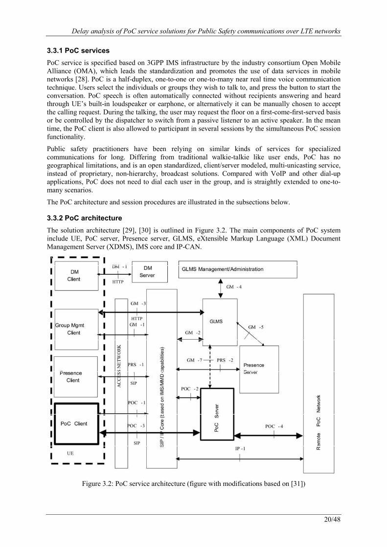
3.3.2 PoC architecture
The solution architecture [29], [30] is outlined in Figure 3.2. The main components of PoC system include UE, PoC server, Presence server, GLMS, eXtensible Markup Language (XML) Document Management Server (XDMS), IMS core and IP-CAN.
HTTP
HTTP
SIP
SIP
Figure 3.2: PoC service architecture (figure with modifications based on [31])

Delay analysis of PoC service solutions for Public Safety communications over LTE networks
21/48
PoC server is a SIP application server that manages the PoC session setup and tearing down procedures, talk burst control (i.e. floor control), and enforces policy defined for PoC group sessions. There are two types of PoC servers: one unique controlling server for each session and one or more participating PoC server functions. The controlling PoC server performs centralized SIP session handling, while participating ones provide local policy enforcement e.g. access control, and charging information. XDMS can be considered as a means of application configuration setting management. It creates, modifies, retrieval, and deletes user-specific service-related information in the form of XML documents. XDMS also applies the client-server model, and the application protocol to support requests and responses is HyperText Transfer Protocol (HTTP) [32] as for Web servers. XDMS is a general framework which is able to handle information associated to not only PoC and Presence, but other kinds of existing and future services as well. Presence server and GLMS, as introduced in 3.2.1, interact with PoC server to provide subscriber states and resource lists manipulation.
3.3.3 PoC protocols
The main protocols applied for PoC service are SIP, Real-time Transport Protocol (RTP) and Real-time Transport Control Protocol (RTCP) [33], all of them defined by Internet Engineering Task Force (IETF), which is the international community dedicated to the evolution of the Internet. SIP is widely used in IMS to create, modify and terminate multimedia sessions between or among two or more parties. It is a text-based application layer protocol, which may run on top of the Transmission Control Protocol (TCP), User Datagram Protocol (UDP), or Stream Control Transmission Protocol (SCTP) at the transport layer, and IP protocol of the underlying network layer. SIP incorporates many elements of HTTP at the application layer. For PoC, SIP is mainly in charge of session control related signaling. RTP and RTCP protocols are used for transport of real-time data over packet networks. They work together to support the media stream transfer and its signaling of floor control. Both of them run over UDP over IP. The PoC protocol stack is given as in figure 3.3, with the Open Systems Interconnection (OSI) model terminology on the left.
Figure 3.3: PoC protocol stack
3.3.4 PoC procedures
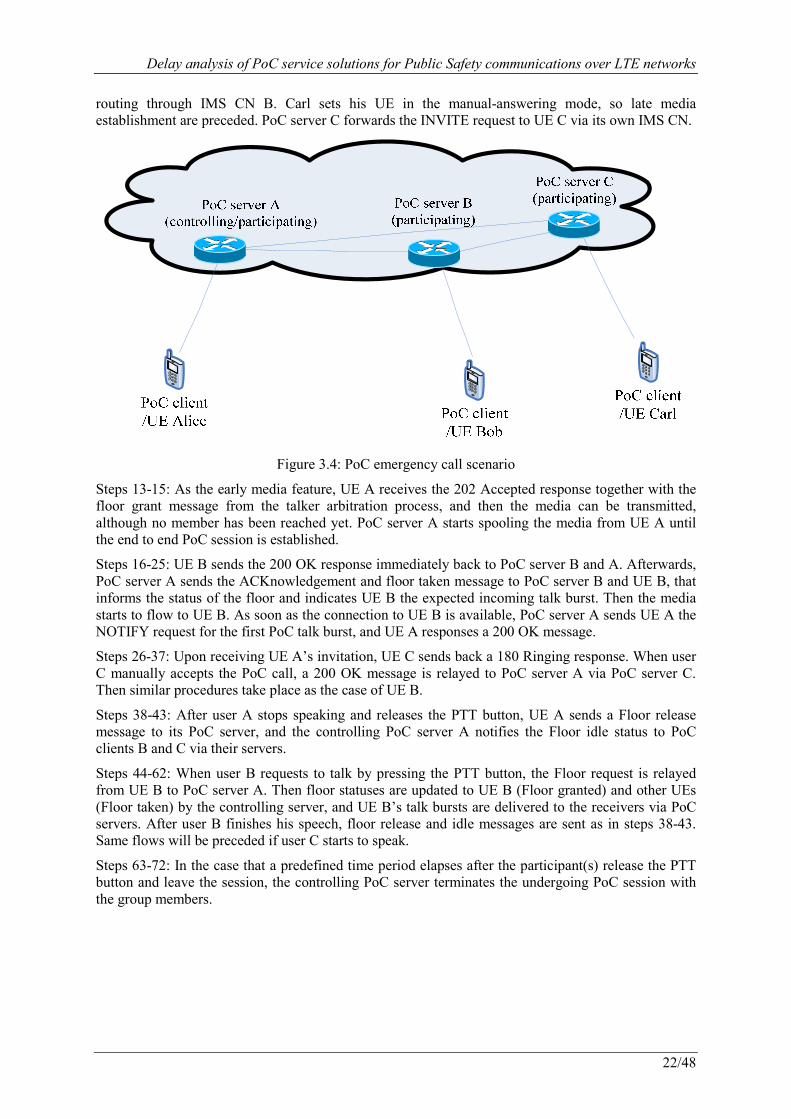
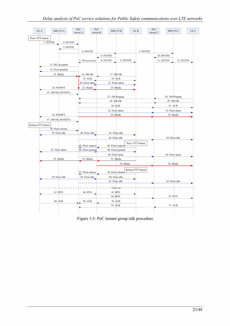
Figure 3.5 shows an example of PoC instant group talk procedures [29], [30]. In this scenario, there are three members in the group from different operator networks. Alice makes an emergency call to talk with Bob and Carl. The two invited members have the auto-answering and the manual-answering mode enabled respectively, as shown in figure 3.4. The signaling flows are explained in the following steps.
Steps 1-5: The initiating user Alice presses the PTT button to invite Bob and Carl into a PoC session. This triggers Alice’s UE to send SIP INVITE messages towards the addresses of Bob and Carl’s UEs. The messages are routed to Alice’s PoC server (controlling/participating) through its IMS CN, and further to the receivers’ PoC servers (participating) via their IMS CNs.
Steps 6-12: Bob uses the auto-answering mode, thus early media mode procedures are followed. PoC server B sends a SIP 183 provisional response to PoC server A and the INVITE message to UE B
Delay analysis of PoC service solutions for Public Safety communications over LTE networks
22/48
routing through IMS CN B. Carl sets his UE in the manual-answering mode, so late media establishment are preceded. PoC server C forwards the INVITE request to UE C via its own IMS CN.
Figure 3.4: PoC emergency call scenario
Steps 13-15: As the early media feature, UE A receives the 202 Accepted response together with the floor grant message from the talker arbitration process, and then the media can be transmitted, although no member has been reached yet. PoC server A starts spooling the media from UE A until the end to end PoC session is established.
Steps 16-25: UE B sends the 200 OK response immediately back to PoC server B and A. Afterwards, PoC server A sends the ACKnowledgement and floor taken message to PoC server B and UE B, that informs the status of the floor and indicates UE B the expected incoming talk burst. Then the media starts to flow to UE B. As soon as the connection to UE B is available, PoC server A sends UE A the NOTIFY request for the first PoC talk burst, and UE A responses a 200 OK message.
Steps 26-37: Upon receiving UE A’s invitation, UE C sends back a 180 Ringing response. When user C manually accepts the PoC call, a 200 OK message is relayed to PoC server A via PoC server C. Then similar procedures take place as the case of UE B.
Steps 38-43: After user A stops speaking and releases the PTT button, UE A sends a Floor release message to its PoC server, and the controlling PoC server A notifies the Floor idle status to PoC clients B and C via their servers.
Steps 44-62: When user B requests to talk by pressing the PTT button, the Floor request is relayed from UE B to PoC server A. Then floor statuses are updated to UE B (Floor granted) and other UEs (Floor taken) by the controlling server, and UE B’s talk bursts are delivered to the receivers via PoC servers. After user B finishes his speech, floor release and idle messages are sent as in steps 38-43. Same flows will be preceded if user C starts to speak.
Steps 63-72: In the case that a predefined time period elapses after the participant(s) release the PTT button and leave the session, the controlling PoC server terminates the undergoing PoC session with the group members.
Delay analysis of PoC service solutions for Public Safety communications over LTE networks
23/48
UE A UE B UE CPoC
server APoC
server BPoC
server CIMS CN A IMS CN B IMS CN C
1. INVITE 2. INVITE
3. INVITE
4. INVITE
6. INVITE
8. INVITE 9. INVITE
10. INVITE
11. INVITE 12. INVITE
5. INVITE
7. 183 provisional
14. Floor granted
13. 202 Accepted
15. Media 17. 200 OK
18. ACK
20. Floor taken
22. Media 23. Media
21. Floor taken
16. 200 OK
19. ACK
24. NOTIFY
25. 200 OK (NOTIFY)
26. 180 Ringing27. 180 Ringing
28. 200 OK29. 200 OK
31. ACK30. ACK
32. Floor taken 33. Floor taken
35. Media34. Media36. NOTIFY
37. 200 OK (NOTIFY)
39. Floor idle
38. Floor release
43. Floor idle
40. Floor idle 41. Floor idle
42. Floor idle
45. Floor request 44. Floor request
46. Floor granted 48. Floor granted47. Floor taken
50. Floor taken49. Floor taken
52. Media 51. Media53. Media
55. Media54. Media
57. Floor release 56. Floor release
59. Floor idle 58. Floor idle 60. Floor idle
62. Floor idle61. Floor idle
Time out
63. BYE 65. BYE64. BYE
67. BYE66. BYE
68. ACK 70. ACK69. ACK
71. ACK72. ACK
Release PTT button
Release PTT button
Press PTT button
Press PTT button
Figure 3.5: PoC instant group talk procedure
Delay analysis of PoC service solutions for Public Safety communications over LTE networks
24/48
4. Delay Analysis As the time-critical nature of emergencies, public safety communications systems must meet the needs of stringent time constraints. In retrospect, low latency is one of the most important issues in commercial cellular systems before 3G to enable first responders to compete with the precious time to save lives and properties. This section will firstly give a survey of delay target recommendations, and then provide an analytical analysis for the delays of IMS-based PoC service via LTE networks.
4.1 PoC delay targets
A typical PoC call on the whole involves session management latency (including session set up and session join-in delay), floor control latency, and end to end media transfer latency. Besides, group management processions and the like should also be taken into account. Next Subsections 4.1.1 and 4.1.2 summarize these PoC delay target values with detailed parameters for commercial mobile networks and public safety systems respectively.
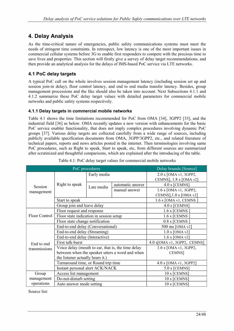
4.1.1 Delay targets in commercial mobile networks
Table 4.1 shows the time limitations recommended for PoC from OMA [34], 3GPP2 [35], and the industrial field [36] as below. OMA recently updates a new version with enhancements for the basic PoC service enabler functionality, that does not imply complex procedures involving dynamic PoC groups [37]. Various delay targets are collected carefully from a wide range of sources, including publicly available specification documents from OMA, 3GPP/3GPP2, etc., and related literature of technical papers, reports and news articles posted in the internet. Then terminologies involving same PoC procedures, such as Right to speak, Start to speak, etc, from different sources are summarized after scrutinized and thoughtful comparisons, which are explained after the introducing of the table.
Table 4.1: PoC delay target values for commercial mobile networks
PoC procedures Delay bounds [Source]
Session management
Right to speak
Early media 2.0 s [OMA v1, 3GPP2, CEMNS], 1.8 s [OMA v2]
Late media automatic answer 4.0 s [CEMNS] manual answer 1.6 s [OMA v1, 3GPP2,
CEMNS],1.0 s [OMA v2] Start to speak 1.6 s [OMA v1, CEMNS ] Group join and leave delay 4.0 s [CEMNS]
Floor Control
Floor request and response 1.6 s [CEMNS ] Floor state indication in session setup 1.6 s [CEMNS ] Floor state change notification 0.8 s [CEMNS ]
End to end
transmissions
End-to-end delay (Conversational) 500 ms [OMA v2] End-to-end delay (Streaming) 1.0 s [OMA v2] End-to-end delay (Interactive) 1.6 s [OMA v2] First talk-burst 4.0 s[OMA v1, 3GPP2, CEMNS] Voice delay (mouth to ear, that is, the time delay between when the speaker utters a word and when the listener actually hears it.)
1.6 s [OMA v1, 3GPP2, CEMNS]
Turnaround time, or Round trip time 4.0 s [OMA v1, 3GPP2] Instant personal alert ACK/NACK 5.0 s [CEMNS]
Group management operations
Access list management 10 s [CEMNS] Do-not-disturb setting 10 s [CEMNS] Auto answer mode setting 10 s [CEMNS]
Source list:
Delay analysis of PoC service solutions for Public Safety communications over LTE networks
25/48
A. OMA v1: Open Mobile Alliance, Push to Talk over Cellular Requirements (Approved Version 1.0 – 09 June 2006), OMA-RD-PoC-V1_0-20060609-A.
B. OMA v2: Open Mobile Alliance, Push to Talk over Cellular Requirements (Approved Version 2.0 – 02 Aug 2011), OMA-RD-PoC-V2_0-20110802-A.
C. 3GPP2: 3GPP2 S.R0100: Push-to-Talk over Cellular (PoC) System Requirements, Version 1.0.
D. CEMNS: Comneon, Ericsson, Motorola, Nokia, Siemens. Push-to-talk over Cellular (PoC) User Requirements; Release 2.0.
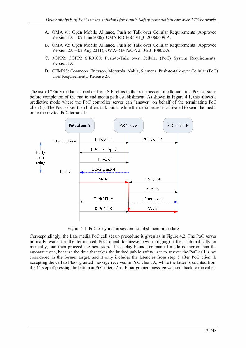
The use of “Early media” carried on from SIP refers to the transmission of talk burst in a PoC sessions before completion of the end to end media path establishment. As shown in Figure 4.1, this allows a predictive mode where the PoC controller server can "answer" on behalf of the terminating PoC client(s). The PoC server then buffers talk bursts while the radio bearer is activated to send the media on to the invited PoC terminal.
Figure 4.1: PoC early media session establishment procedure
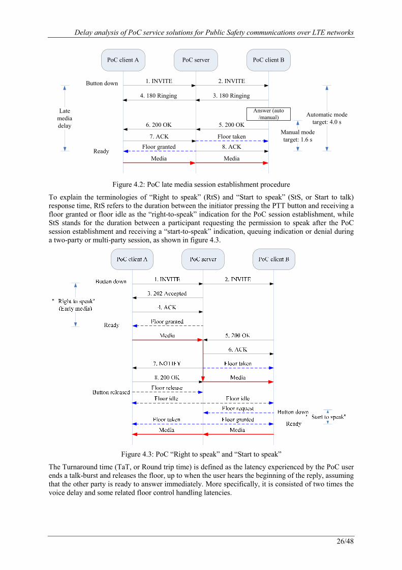
Correspondingly, the Late media PoC call set up procedure is given as in Figure 4.2. The PoC server normally waits for the terminated PoC client to answer (with ringing) either automatically or manually, and then proceed the next steps. The delay bound for manual mode is shorter than the automatic one, because the time that takes the invited public safety user to answer the PoC call is not considered in the former target, and it only includes the latencies from step 5 after PoC client B accepting the call to Floor granted message received in PoC client A, while the latter is counted from the 1st step of pressing the button at PoC client A to Floor granted message was sent back to the caller.
Delay analysis of PoC service solutions for Public Safety communications over LTE networks
26/48
PoC client A PoC server PoC client B
1. INVITE 2. INVITE
7. ACK
Floor granted
5. 200 OK
8. ACK
Media Media
Floor taken
Button down
Ready
3. 180 Ringing4. 180 Ringing
6. 200 OK
Latemediadelay
Automatic modetarget: 4.0 s
Manual modetarget: 1.6 s
Answer (auto/manual)
Figure 4.2: PoC late media session establishment procedure
To explain the terminologies of “Right to speak” (RtS) and “Start to speak” (StS, or Start to talk) response time, RtS refers to the duration between the initiator pressing the PTT button and receiving a floor granted or floor idle as the “right-to-speak” indication for the PoC session establishment, while StS stands for the duration between a participant requesting the permission to speak after the PoC session establishment and receiving a “start-to-speak” indication, queuing indication or denial during a two-party or multi-party session, as shown in figure 4.3.
Figure 4.3: PoC “Right to speak” and “Start to speak”
The Turnaround time (TaT, or Round trip time) is defined as the latency experienced by the PoC user ends a talk-burst and releases the floor, up to when the user hears the beginning of the reply, assuming that the other party is ready to answer immediately. More specifically, it is consisted of two times the voice delay and some related floor control handling latencies.

Delay analysis of PoC service solutions for Public Safety communications over LTE networks
27/48
Note that the end-to-end delay for conversational traffic class in table 4.1 applies to the case of PoC voice call to be analyzed, while the ones for streaming and interactive classes may be considered for Push To Image, Push To Video, Push To Connect and future generalized services.
4.1.2 Delay targets for public safety communication networks
Generally speaking, public safety users are expected to make a fast connection with a large group in approximately 500 milliseconds [13], and one-third of a second or less in the same ‘cell’ or localised area on 95% occasions [38], [39]. Typical TETRA call set up time can reach 200 msec [40], and the end to end voice delay is expected to be 200 msec [41]. Note that TETRA requirements specifications [42], [43] only provide information about functionality details, but not technical requirements.
Safecom’s requirements from USA Department of Homeland Security suggests the maximum call setup time to be as short as 250 msec, and the acceptable upper bound for the mouth to ear end-to-end delay to be 200 msec [25]. An updated version reduces the mouth to ear delay to be 150 msec [44].
P25 [45] also has mouth-to-ear transfer delays for public safety use, which is specified not to exceed 250 msec for direct radio-to-radio communications, 350 msec for communications through a single conventional repeater, 500 msec within a single RF subsystem, and 1000 msec for multiple RF subsystems.
Moreover, the Mobility for Emergency and Safety Applications (MESA) Project [46], a partnership between ETSI and US Telecommunications Industry Association (TIA), proposes the end-to-end transmission to take place “almost instantaneously” with a delay of 250 ms for half-duplex systems [47].
Recently, ETSI Technical Committee (TC) TETRA sent a liaison statement to 3GPP to propose the group call establishment time for mission/business critical communication over LTE networks to be 300 msec [48]. In the near future, 3GPP will provide delay requirements for the public safety communications in Release 12.
Table 4.2 gives a summary of delay target values for public safety networks, based on the following source list. Note the changeover budget corresponds to the floor change in PoC sessions. In comparison, call set up time and end to end delays for public safety purpose are twice or even more stricter than those for commercial use in previous subsection.
Table 4.2: Delay target values for public safety networks
Delays Targets (msec) [Source�
Call set up delay
trunked group calls supported 200 [TETRA Motorola] maximum call setup time
250 [SAFECOM v1.0], 300 [TETRA Book , TETRA LTE ],
500 [TETRA MoU ]
End to end delay
mouth-to-ear delay 150 [SAFECOM v1.2], 200 [SAFECOM v1.0]
end to end voice delay 200 [TETRA Mason] duplex systems (voice) 150 [MESA] half-duplex systems (voice) 250 [MESA] non-terrestrial communications 400 [MESA] “mouth-to-ear” direct 250 [P25] “mouth-to-ear” single repeater 350 [P25] “mouth-to-ear” single RF 500 [P25] “mouth-to-ear” multi RF 1000 [P25]
Source list:
A. TETRA MoU: TETRA MoU Association. Push To Talk over Cellular (PoC) and Professional Mobile Radio (PMR).
Delay analysis of PoC service solutions for Public Safety communications over LTE networks
28/48
B. TETRA Book: Peter Stavroulakis, TErrestrial Trunked RAdio – TETRA. Springer, 2007.
C. TETRA Motorola: Motorola POSITION PAPER. Ensuring Resilience and Availability in a TETRA System.
D. TETRA Mason: Analysys Mason. Report for the TETRA Association-Public safety mobile broadband and spectrum needs.
E. TETRA LTE: 3GPP Liaison Statement S1-121247: Information about the system improvements requirements for the adoption of LTE for mission/business critical communications.
F. SAFECOM v1.0: The SAFECOM Program - Department of Homeland Security. Statement of Requirements, Version 1.0.
G. SAFECOM v1.2: Office for Interoperability and Compatibility - Department of Homeland Security. Public Safety Statement of Requirements for Interoperability and Compatibility, Volumn II, Version 1.2.
H. P25: APCO Project 25 Statement of Requirements (P25 SoR).
I. MESA: MESA TS 70.001: Project MESA; Service Specification Group - Services and Applications; Statement of Requirements (SoR) V3.3.1.
4.2 PoC delay assumptions
The delay analysis is under the following assumptions:
· The difference between the UEs near the centre of the cell and around the edge of the cell is negligible at the level of milliseconds or below.
· The queuing delay or congestion problem in the end to end transmissions is out of the scope of this thesis, as it also relates to the network deployments and optimizations.
· We begin with the assumption the caller and the callee are in the same home network, thus there is no influence from the roaming procedures, then possible extensions can be added to cover this aspect.
· UEs are supposed to complete the registration and cell selection processes in the public safety communication network, either in idle mode, or in active/dormant state of connected mode.
· For simplicity, all UEs are assumed to be assigned with the same level of priorities, and are allocated with the same radio resources.
4.3 PoC delay calculations
The PoC delay is calculated by means of dividing the whole latency into delay components of LTE and IMS network functionalities. According to the guidelines of International Telecommunications Union (ITU) [49], [50], the delay components in EPS are divided into C-Plane and U-plane two classes. As shown in equation 4.1 and the analytic model in figure 4.4, a PoC delay includes LTE delay of the air interface and EPC parts, and IMS delay from the IP backbone and service layer.
Figure 4.4: The analytic model for PoC delay calculation
Delay analysis of PoC service solutions for Public Safety communications over LTE networks
29/48
_ _ _ _total LTE IMS Air Interface EPC IMS backbone IMS service layerτ τ τ τ τ τ τ= + = + + + (4.1)
4.3.1 Delay components in LTE (E-UTRAN and EPC)
In this subsection, we present a breakdown of the typical latencies for UEs to connect to LTE networks from the idle mode following the methodology above.
Control-Plane latencies:
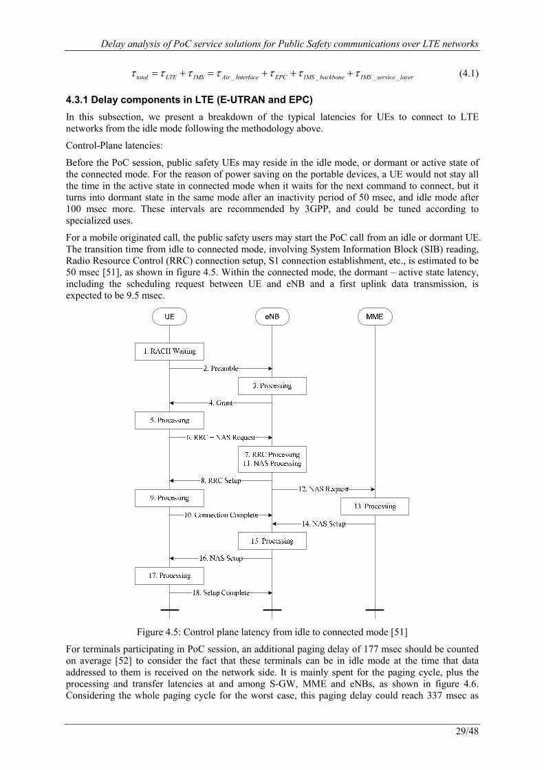
Before the PoC session, public safety UEs may reside in the idle mode, or dormant or active state of the connected mode. For the reason of power saving on the portable devices, a UE would not stay all the time in the active state in connected mode when it waits for the next command to connect, but it turns into dormant state in the same mode after an inactivity period of 50 msec, and idle mode after 100 msec more. These intervals are recommended by 3GPP, and could be tuned according to specialized uses.
For a mobile originated call, the public safety users may start the PoC call from an idle or dormant UE. The transition time from idle to connected mode, involving System Information Block (SIB) reading, Radio Resource Control (RRC) connection setup, S1 connection establishment, etc., is estimated to be 50 msec [51], as shown in figure 4.5. Within the connected mode, the dormant – active state latency, including the scheduling request between UE and eNB and a first uplink data transmission, is expected to be 9.5 msec.
Figure 4.5: Control plane latency from idle to connected mode [51]
For terminals participating in PoC session, an additional paging delay of 177 msec should be counted on average [52] to consider the fact that these terminals can be in idle mode at the time that data addressed to them is received on the network side. It is mainly spent for the paging cycle, plus the processing and transfer latencies at and among S-GW, MME and eNBs, as shown in figure 4.6. Considering the whole paging cycle for the worst case, this paging delay could reach 337 msec as
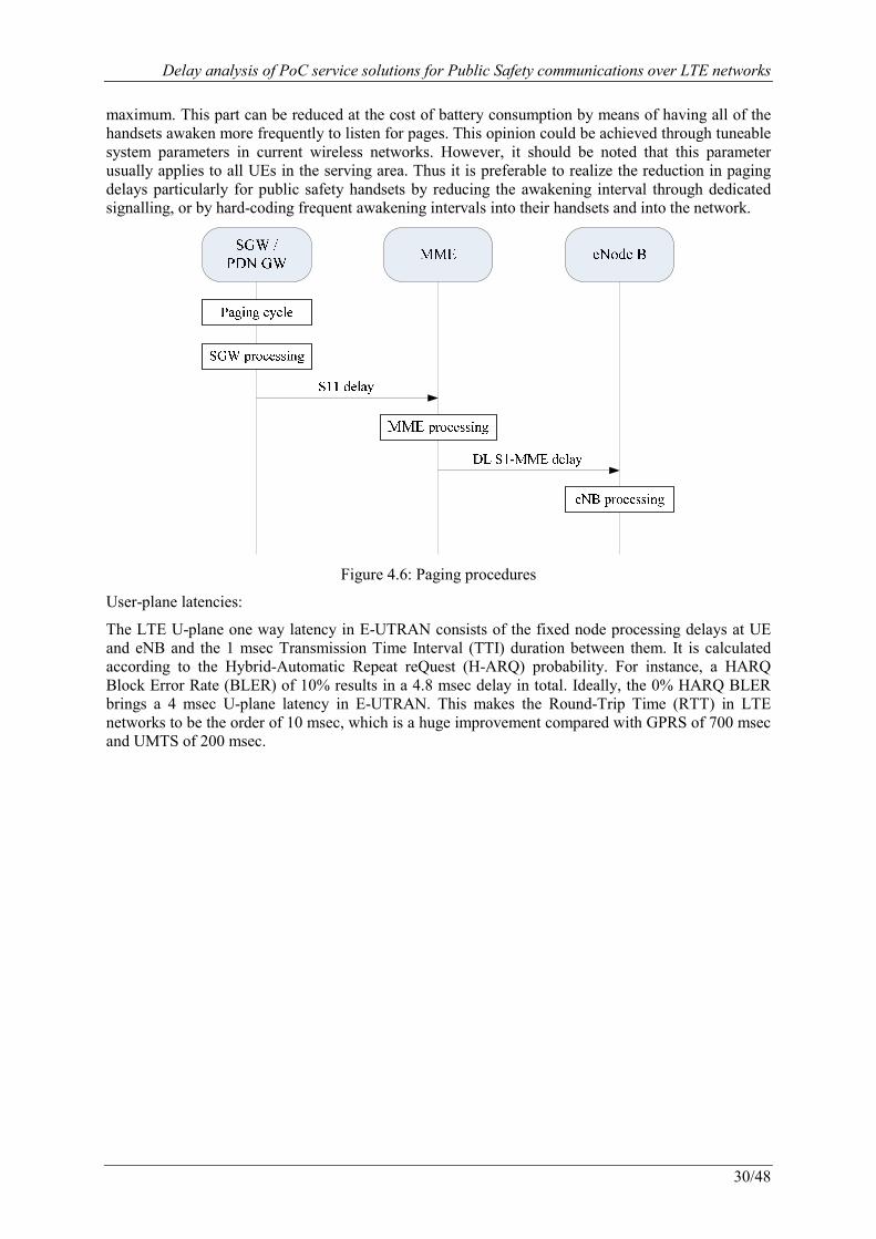
Delay analysis of PoC service solutions for Public Safety communications over LTE networks
30/48
maximum. This part can be reduced at the cost of battery consumption by means of having all of the handsets awaken more frequently to listen for pages. This opinion could be achieved through tuneable system parameters in current wireless networks. However, it should be noted that this parameter usually applies to all UEs in the serving area. Thus it is preferable to realize the reduction in paging delays particularly for public safety handsets by reducing the awakening interval through dedicated signalling, or by hard-coding frequent awakening intervals into their handsets and into the network.
Figure 4.6: Paging procedures
User-plane latencies:
The LTE U-plane one way latency in E-UTRAN consists of the fixed node processing delays at UE and eNB and the 1 msec Transmission Time Interval (TTI) duration between them. It is calculated according to the Hybrid-Automatic Repeat reQuest (H-ARQ) probability. For instance, a HARQ Block Error Rate (BLER) of 10% results in a 4.8 msec delay in total. Ideally, the 0% HARQ BLER brings a 4 msec U-plane latency in E-UTRAN. This makes the Round-Trip Time (RTT) in LTE networks to be the order of 10 msec, which is a huge improvement compared with GPRS of 700 msec and UMTS of 200 msec.

Delay analysis of PoC service solutions for Public Safety communications over LTE networks
31/48
Access Network (B side)
IP
Application / Service Level
Send/Rcv
Access Network (A side)
Send/Rcv
UE PDNGW
Scope of the standardizedQCI characteristics UE PDN
GWScope of the standardizedQCI characteristicsBackbone
IP
Application / Service Level
Send/Rcv
Access Network (A side)
Send/Rcv
UE PDNGW
Scope of the standardizedQCI characteristics Server Backbone
Access Network (B side)
IP
Application / Service Level
Send/Rcv
Access Network (A side)
Send/Rcv
UE PDNGW
Scope of the standardizedQCI characteristics UE PDN
GWScope of the standardizedQCI characteristicsBackbone
Access Network (B side)
IP
Application / Service Level
Send/Rcv
Access Network (A side)
Send/Rcv
UE PDNGW
Scope of the standardizedQCI characteristicsUE PCEFScope of the standardizedQCI characteristics UE PDN
GWScope of the standardizedQCI characteristics UE PCEF Scope of the standardizedQCI characteristicsBackbone
IP
Application / Service Level
Send/Rcv
Access Network (A side)
Send/Rcv
UE PDNGW
Scope of the standardizedQCI characteristics Server Backbone
IP
Application / Service Level
Send/Rcv
Access Network (A side)
Send/Rcv
UE PDNScope of the standardizedQCI characteristicsUE PCEF Scope of the standardizedQCI characteristics Server Backbone
(a) Scope of the Standardized QCI characteristics for client/server (upper figure) and peer/peer (lower
figure) communication [54] between UE and EPC
(b) E-UTRAN and EPC latencies
Figure 4.7: User-plane latency
The U-plane latency in E-UTRAN and EPC at the gateways and PCC functionalities could be estimated as 100 msec [53], [54], as shown in figure 4.7. This LTE U-plane transfer latency may vary around 100 msec according to the packet QoS Class Identifier (QCI) as shown in table 4.3. Therefore, the total delay in C-Plane and U-plane altogether reaches 150 msec for a mobile oriented call from the idle mode, and 437 msec for a mobile terminated call.
Table 4.3: LTE U-plane transfer delay budget and QCI characteristics, extracted from [54]
QCI Resource Type Priority Delay Budget Example Services 1
Guaranteed Bit Rate (GBR)
2 100 msec Conversational Voice 2 4 150 msec Conversational Video (Live Streaming) 3 3 50 msec Real Time Gaming 4 5 300 msec Non-Conversational Video (Buffered Streaming) 5
Non-GBR
1 100 msec IMS Signalling 6 6 300 msec Video (Buffered Streaming), TCP-based services 7 7 100 msec Voice, Video (Live), Interactive Gaming 8 8 300 msec Video (Buffered Streaming), TCP-based services 9 9
A summary of the delay components in LTE networks discussed in this subsection is given in table 4.4. Compared with the before 3G techniques, LTE benefits greatly from the flat architecture in E-
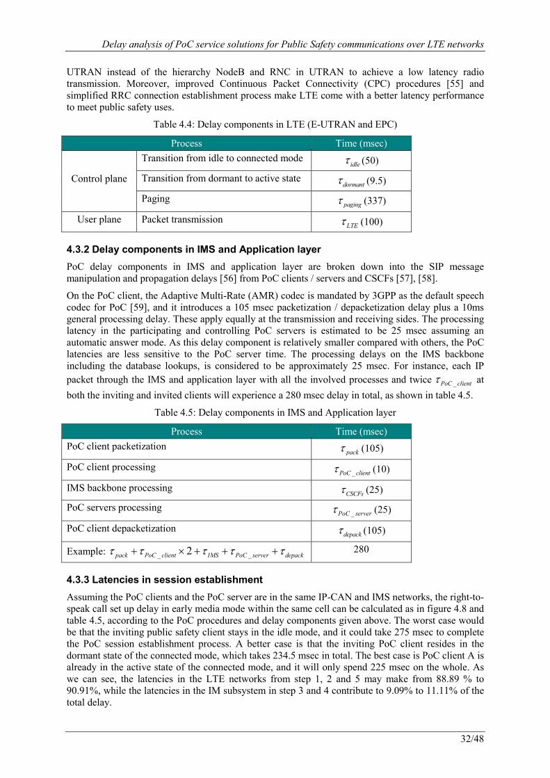
Delay analysis of PoC service solutions for Public Safety communications over LTE networks
32/48
UTRAN instead of the hierarchy NodeB and RNC in UTRAN to achieve a low latency radio transmission. Moreover, improved Continuous Packet Connectivity (CPC) procedures [55] and simplified RRC connection establishment process make LTE come with a better latency performance to meet public safety uses.
Table 4.4: Delay components in LTE (E-UTRAN and EPC)
Process Time (msec)
Control plane
Transition from idle to connected mode idleτ (50)
Transition from dormant to active state dormantτ (9.5)
Paging pagingτ (337)
User plane Packet transmission LTEτ (100)
4.3.2 Delay components in IMS and Application layer
PoC delay components in IMS and application layer are broken down into the SIP message manipulation and propagation delays [56] from PoC clients / servers and CSCFs [57], [58].
On the PoC client, the Adaptive Multi-Rate (AMR) codec is mandated by 3GPP as the default speech codec for PoC [59], and it introduces a 105 msec packetization / depacketization delay plus a 10ms general processing delay. These apply equally at the transmission and receiving sides. The processing latency in the participating and controlling PoC servers is estimated to be 25 msec assuming an automatic answer mode. As this delay component is relatively smaller compared with others, the PoC latencies are less sensitive to the PoC server time. The processing delays on the IMS backbone including the database lookups, is considered to be approximately 25 msec. For instance, each IP packet through the IMS and application layer with all the involved processes and twice _PoC clientτ at
both the inviting and invited clients will experience a 280 msec delay in total, as shown in table 4.5.
Table 4.5: Delay components in IMS and Application layer
Process Time (msec) PoC client packetization
packτ (105)
PoC client processing _PoC clientτ (10)
IMS backbone processing CSCFsτ (25)
PoC servers processing _PoC serverτ (25)
PoC client depacketization depackτ (105)
Example: _ _2pack PoC client IMS PoC server depackτ τ τ τ τ+ × + + + 280
4.3.3 Latencies in session establishment
Assuming the PoC clients and the PoC server are in the same IP-CAN and IMS networks, the right-to-speak call set up delay in early media mode within the same cell can be calculated as in figure 4.8 and table 4.5, according to the PoC procedures and delay components given above. The worst case would be that the inviting public safety client stays in the idle mode, and it could take 275 msec to complete the PoC session establishment process. A better case is that the inviting PoC client resides in the dormant state of the connected mode, which takes 234.5 msec in total. The best case is PoC client A is already in the active state of the connected mode, and it will only spend 225 msec on the whole. As we can see, the latencies in the LTE networks from step 1, 2 and 5 may make from 88.89 % to 90.91%, while the latencies in the IM subsystem in step 3 and 4 contribute to 9.09% to 11.11% of the total delay.
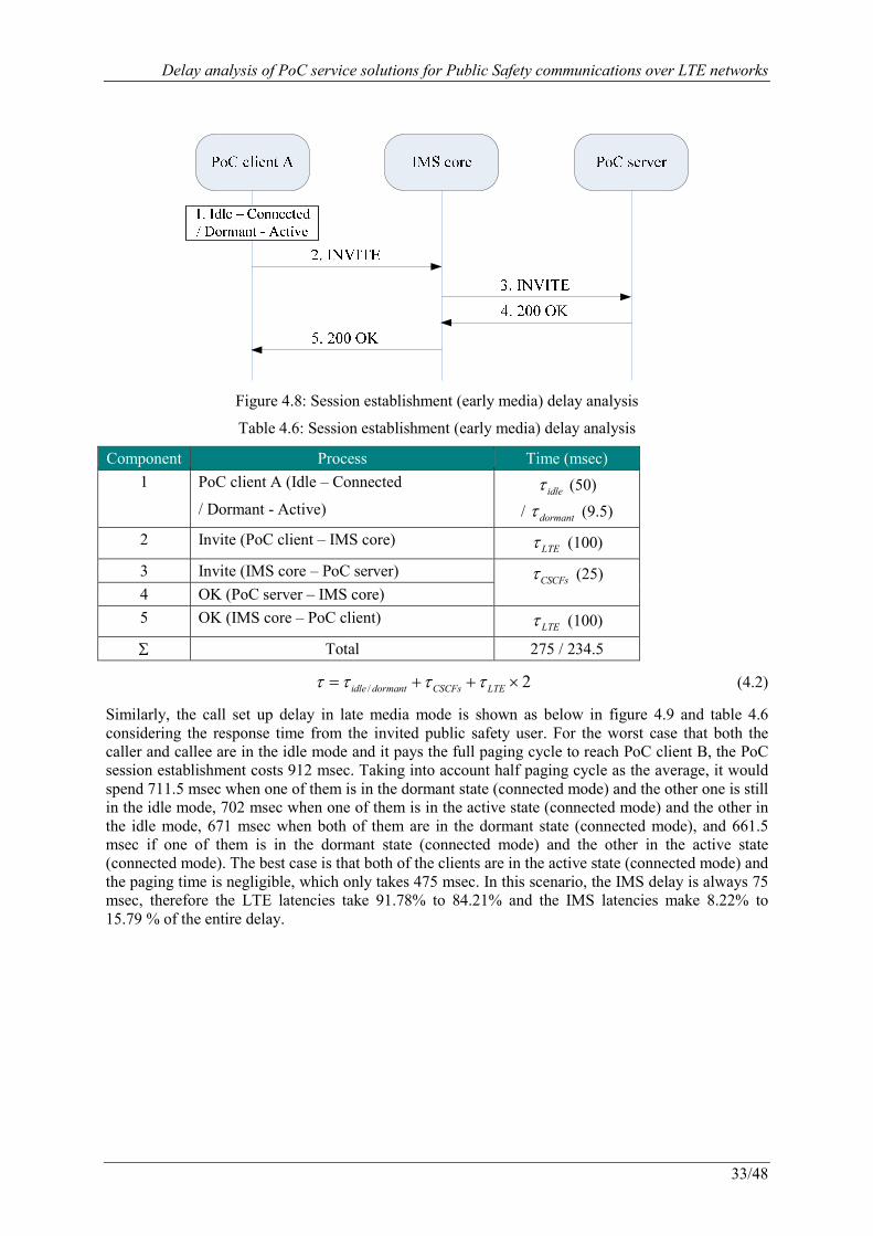
Delay analysis of PoC service solutions for Public Safety communications over LTE networks
33/48
Figure 4.8: Session establishment (early media) delay analysis
Table 4.6: Session establishment (early media) delay analysis
Component Process Time (msec) 1 PoC client A (Idle – Connected
/ Dormant - Active) idleτ (50)
/ dormantτ (9.5)
2 Invite (PoC client – IMS core) LTEτ (100)
3 Invite (IMS core – PoC server) CSCFsτ (25)
4 OK (PoC server – IMS core) 5 OK (IMS core – PoC client)
LTEτ (100)
Σ Total 275 / 234.5
/ 2idle dormant CSCFs LTEτ τ τ τ= + + × (4.2)
Similarly, the call set up delay in late media mode is shown as below in figure 4.9 and table 4.6 considering the response time from the invited public safety user. For the worst case that both the caller and callee are in the idle mode and it pays the full paging cycle to reach PoC client B, the PoC session establishment costs 912 msec. Taking into account half paging cycle as the average, it would spend 711.5 msec when one of them is in the dormant state (connected mode) and the other one is still in the idle mode, 702 msec when one of them is in the active state (connected mode) and the other in the idle mode, 671 msec when both of them are in the dormant state (connected mode), and 661.5 msec if one of them is in the dormant state (connected mode) and the other in the active state (connected mode). The best case is that both of the clients are in the active state (connected mode) and the paging time is negligible, which only takes 475 msec. In this scenario, the IMS delay is always 75 msec, therefore the LTE latencies take 91.78% to 84.21% and the IMS latencies make 8.22% to 15.79 % of the entire delay.
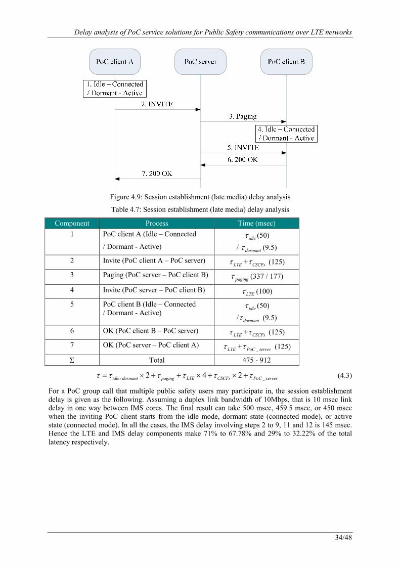
Delay analysis of PoC service solutions for Public Safety communications over LTE networks
34/48
Figure 4.9: Session establishment (late media) delay analysis
Table 4.7: Session establishment (late media) delay analysis
Component Process Time (msec) 1 PoC client A (Idle – Connected
/ Dormant - Active) idleτ (50)
/ dormantτ (9.5)
2 Invite (PoC client A – PoC server) LTEτ + CSCFsτ (125)
3 Paging (PoC server – PoC client B) pagingτ (337 / 177)
4 Invite (PoC server – PoC client B) LTEτ (100)
5 PoC client B (Idle – Connected / Dormant - Active)
idleτ (50)
/ dormantτ (9.5)
6 OK (PoC client B – PoC server) LTEτ + CSCFsτ (125)
7 OK (PoC server – PoC client A) LTEτ + _PoC serverτ (125)
Σ Total 475 - 912
/ _2 4 2idle dormant paging LTE CSCFs PoC serverτ τ τ τ τ τ= × + + × + × + (4.3)
For a PoC group call that multiple public safety users may participate in, the session establishment delay is given as the following. Assuming a duplex link bandwidth of 10Mbps, that is 10 msec link delay in one way between IMS cores. The final result can take 500 msec, 459.5 msec, or 450 msec when the inviting PoC client starts from the idle mode, dormant state (connected mode), or active state (connected mode). In all the cases, the IMS delay involving steps 2 to 9, 11 and 12 is 145 msec. Hence the LTE and IMS delay components make 71% to 67.78% and 29% to 32.22% of the total latency respectively.

Delay analysis of PoC service solutions for Public Safety communications over LTE networks
35/48
Figure 4.10: Group session establishment (early media) delay analysis
Table 4.8: Group session establishment (early media) delay analysis
Component Process Time (msec) 0 PoC client A (Idle – Connected
/ Dormant - Active) idleτ (50)
/ dormantτ (9.5)
1 Invite (PoC client – IMS core A) LTEτ (100)
2 Invite (IMS core A – PoC server A) CSCFsτ (25)
3 Invite (PoC server A – IMS core A) 4 Invite (IMS core A – IMS core X)
inter-IMSτ (10)
5 Invite (IMS core X - PoC server X) CSCFsτ + _PoC serverτ (50)
6 Alerting (PoC server X – IMS core X) 7 Alerting (IMS core X - IMS core A)
inter-IMSτ (10)
8 Alerting (IMS core A – PoC server A) CSCFsτ (25)
9 Alerting (PoC server A – IMS core A) 10 Alerting (IMS core A – PoC client)
LTEτ (100)
11 OK (IMS core A – PoC server A) CSCFsτ (25)
12 OK (PoC server A – IMS core A) 13 OK (IMS core A – PoC client)
LTEτ (100)
Σ Total 495 / 454.5
/ _3 4 2idle dormant LTE CSCFs inter-IMS PoC serverτ τ τ τ τ τ= + × + × + × + (4.4)
To have an insight about these results, an overview of the percentage of main delay components is provided in table 4.8 and figure 4.11. It can be observed that LTE signalling transfer latencies in general make the main contribution of the total delay in all kinds of session establishment procedures, although this part is already remarkably decreased compared with before 3G networks. On the contrary, the processing latencies on the IMS nodes including PoC Clients/Servers are always a small
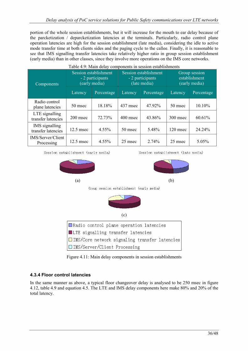
Delay analysis of PoC service solutions for Public Safety communications over LTE networks
36/48
portion of the whole session establishments, but it will increase for the mouth to ear delay because of the parcketization / deparcketization latencies at the terminals. Particularly, radio control plane operation latencies are high for the session establishment (late media), considering the idle to active mode transfer time at both clients sides and the paging cycle to the callee. Finally, it is reasonable to see that IMS signalling transfer latencies take relatively higher ratio in group session establishment (early media) than in other classes, since they involve more operations on the IMS core networks.
Table 4.9: Main delay components in session establishments
Components
Session establishment - 2 participants (early media)
Session establishment - 2 participants (late media)
Group session establishment (early media)
Latency Percentage Latency Percentage Latency Percentage
Radio control plane latencies 50 msec� 18.18%� 437 msec� 47.92% 50 msec� 10.10%�
LTE signalling transfer latencies 200 msec� 72.73%� 400 msec� 43.86% 300 msec� 60.61%�
IMS signalling transfer latencies 12.5 msec� 4.55%� 50 msec� 5.48% 120 msec� 24.24%�
IMS/Server/Client Processing 12.5 msec� 4.55%� 25 msec� 2.74% 25 msec� 5.05%�
(a) (b)
(c)
Figure 4.11: Main delay components in session establishments
4.3.4 Floor control latencies
In the same manner as above, a typical floor changeover delay is analysed to be 250 msec in figure 4.12, table 4.9 and equation 4.5. The LTE and IMS delay components here make 80% and 20% of the total latency.
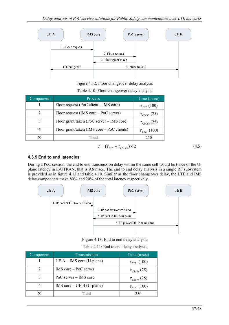
Delay analysis of PoC service solutions for Public Safety communications over LTE networks
37/48
Figure 4.12: Floor changeover delay analysis
Table 4.10: Floor changeover delay analysis
Component Process Time (msec) 1 Floor request (PoC client – IMS core)
LTEτ (100)
2 Floor request (IMS core – PoC server) CSCFsτ (25)
3 Floor grant/taken (PoC server – IMS core) CSCFsτ (25)
4 Floor grant/taken (IMS core – PoC clients) LTEτ (100)
Σ Total 250
( ) 2LTE CSCFsτ τ τ= + × (4.5)
4.3.5 End to end latencies
During a PoC session, the end to end transmission delay within the same cell would be twice of the U-plane latency in E-UTRAN, that is 9.6 msec. The end to end delay analysis in a single RF subsystem is provided as in figure 4.13 and table 4.10. Similar as the floor changeover delay, the LTE and IMS delay components make 80% and 20% of the total latency respectively.
Figure 4.13: End to end delay analysis
Table 4.11: End to end delay analysis
Component Transmission Time (msec) 1 UE A – IMS core (U-plane)
LTEτ (100)
2 IMS core – PoC server CSCFsτ (25)
3 PoC server – IMS core CSCFsτ (25)
4 IMS core – UE B (U-plane) LTEτ (100)
Σ Total 250
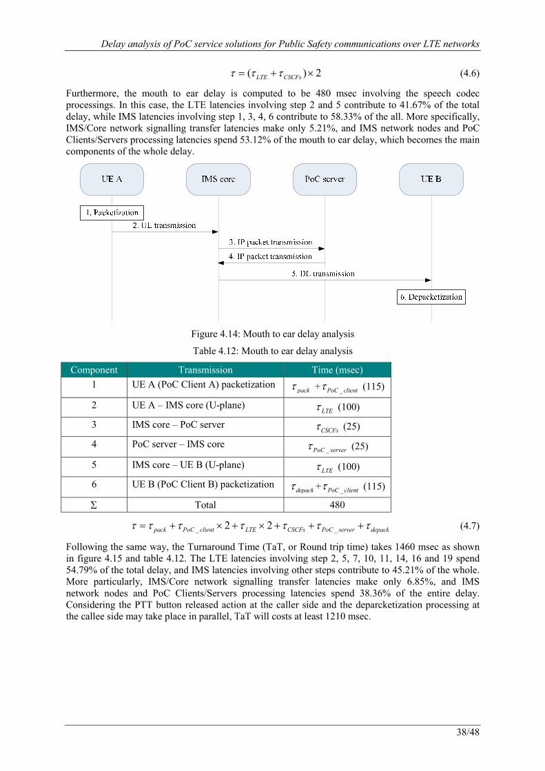
Delay analysis of PoC service solutions for Public Safety communications over LTE networks
38/48
( ) 2LTE CSCFsτ τ τ= + × (4.6)
Furthermore, the mouth to ear delay is computed to be 480 msec involving the speech codec processings. In this case, the LTE latencies involving step 2 and 5 contribute to 41.67% of the total delay, while IMS latencies involving step 1, 3, 4, 6 contribute to 58.33% of the all. More specifically, IMS/Core network signalling transfer latencies make only 5.21%, and IMS network nodes and PoC Clients/Servers processing latencies spend 53.12% of the mouth to ear delay, which becomes the main components of the whole delay.
Figure 4.14: Mouth to ear delay analysis
Table 4.12: Mouth to ear delay analysis
Component Transmission Time (msec) 1 UE A (PoC Client A) packetization
packτ + _PoC clientτ (115)
2 UE A – IMS core (U-plane) LTEτ (100)
3 IMS core – PoC server CSCFsτ (25)
4 PoC server – IMS core _PoC serverτ (25)
5 IMS core – UE B (U-plane) LTEτ (100)
6 UE B (PoC Client B) packetization depackτ + _PoC clientτ (115)
Σ Total 480
_ _2 2pack PoC client LTE CSCFs PoC server depackτ τ τ τ τ τ τ= + × + × + + + (4.7)
Following the same way, the Turnaround Time (TaT, or Round trip time) takes 1460 msec as shown in figure 4.15 and table 4.12. The LTE latencies involving step 2, 5, 7, 10, 11, 14, 16 and 19 spend 54.79% of the total delay, and IMS latencies involving other steps contribute to 45.21% of the whole. More particularly, IMS/Core network signalling transfer latencies make only 6.85%, and IMS network nodes and PoC Clients/Servers processing latencies spend 38.36% of the entire delay. Considering the PTT button released action at the caller side and the deparcketization processing at the callee side may take place in parallel, TaT will costs at least 1210 msec.
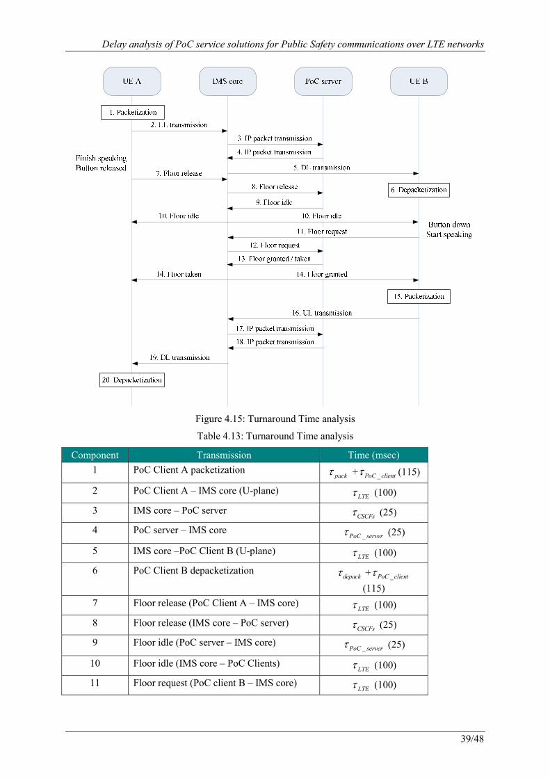
Delay analysis of PoC service solutions for Public Safety communications over LTE networks
39/48
Figure 4.15: Turnaround Time analysis
Table 4.13: Turnaround Time analysis
Component Transmission Time (msec) 1 PoC Client A packetization
packτ + _PoC clientτ (115)
2 PoC Client A – IMS core (U-plane) LTEτ (100)
3 IMS core – PoC server CSCFsτ (25)
4 PoC server – IMS core _PoC serverτ (25)
5 IMS core –PoC Client B (U-plane) LTEτ (100)
6 PoC Client B depacketization depackτ + _PoC clientτ
(115) 7 Floor release (PoC Client A – IMS core)
LTEτ (100)
8 Floor release (IMS core – PoC server) CSCFsτ (25)
9 Floor idle (PoC server – IMS core) _PoC serverτ (25)
10 Floor idle (IMS core – PoC Clients) LTEτ (100)
11 Floor request (PoC client B – IMS core) LTEτ (100)
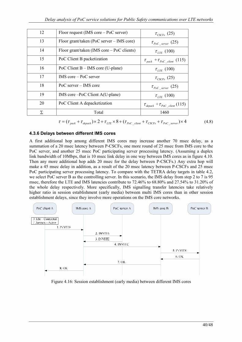
Delay analysis of PoC service solutions for Public Safety communications over LTE networks
40/48
12 Floor request (IMS core – PoC server) CSCFsτ (25)
13 Floor grant/taken (PoC server – IMS core) _PoC serverτ (25)
14 Floor grant/taken (IMS core – PoC clients) LTEτ (100)
15 PoC Client B packetization packτ + _PoC clientτ (115)
16 PoC Client B – IMS core (U-plane) LTEτ (100)
17 IMS core – PoC server CSCFsτ (25)
18 PoC server – IMS core _PoC serverτ (25)
19 IMS core –PoC Client A(U-plane) LTEτ (100)
20 PoC Client A depacketization depackτ + _PoC clientτ (115)
Σ Total 1460
_ _( ) 2 8 ( ) 4pack depack LTE PoC client CSCFs PoC serverτ τ τ τ τ τ τ= + × + × + + + × (4.8)
4.3.6 Delays between different IMS cores
A first additional hop among different IMS cores may increase another 70 msec delay, as a summation of a 20 msec latency between P-CSCFs, one more round of 25 msec from IMS core to the PoC server, and another 25 msec PoC participating server processing latency. (Assuming a duplex link bandwidth of 10Mbps, that is 10 msec link delay in one way between IMS cores as in figure 4.10. Then any more additional hop adds 20 msec for the delay between P-CSCFs.) Any extra hop will make a 45 msec delay in addition, as a result of the 20 msec latency between P-CSCFs and 25 msec PoC participating server processing latency. To compare with the TETRA delay targets in table 4.2, we select PoC server B as the controlling server. In this scenario, the IMS delay from step 2 to 7 is 95 msec, therefore the LTE and IMS latencies contribute to 72.46% to 68.80% and 27.54% to 31.20% of the whole delay respectively. More specifically, IMS signalling transfer latencies take relatively higher ratio in session establishment (early media) between multi IMS cores than in other session establishment delays, since they involve more operations on the IMS core networks.
Figure 4.16: Session establishment (early media) between different IMS cores
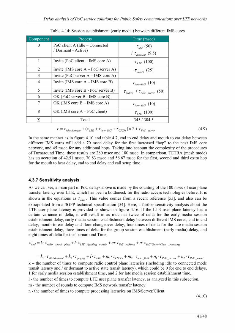
Delay analysis of PoC service solutions for Public Safety communications over LTE networks
41/48
Table 4.14: Session establishment (early media) between different IMS cores
Component Process Time (msec) 0 PoC client A (Idle – Connected
/ Dormant - Active) idleτ (50)
/ dormantτ (9.5)
1 Invite (PoC client – IMS core A) LTEτ (100)
2 Invite (IMS core A – PoC server A) CSCFsτ (25)
3 Invite (PoC server A – IMS core A) 4 Invite (IMS core A – IMS core B)
inter-IMSτ (10)
5 Invite (IMS core B - PoC server B) CSCFsτ + _PoC serverτ (50)
6 OK (PoC server B– IMS core B) 7 OK (IMS core B – IMS core A)
inter-IMSτ (10)
8 OK (IMS core A – PoC client) LTEτ (100)
Σ Total 345 / 304.5
/ _( ) 2idle dormant LTE inter-IMS CSCFs PoC serverτ τ τ τ τ τ= + + + × + (4.9)
In the same manner as in figure 4.10 and table 4.7, end to end delay and mouth to ear delay between different IMS cores will add a 70 msec delay for the first increased “hop” to the next IMS core network, and 45 msec for any additional hops. Taking into account the complexity of the procedures of Turnaround Time, these results are 280 msec and 180 msec. In comparison, TETRA (mesh mode) has an accretion of 42.51 msec, 70.83 msec and 56.67 msec for the first, second and third extra hop for the mouth to hear delay, end to end delay and call setup time.
4.3.7 Sensitivity analysis
As we can see, a main part of PoC delays above is made by the counting of the 100 msec of user plane transfer latency over LTE, which has been a bottleneck for the radio access technologies before. It is shown in the equations as LTEτ . This value comes from a recent reference [53], and also can be extrapolated from a 3GPP technical specification [54]. Here, a further sensitivity analysis about the LTE user plane latency is provided as shown in figure 4.16. If the LTE user plane latency has a certain variance of delta, it will result in as much as twice of delta for the early media session establishment delay, early media session establishment delay between different IMS cores, end to end delay, mouth to ear delay and floor changeover delay, four times of delta for the late media session establishment delay, three times of delta for the group session establishment (early media) delay, and eight times of delta for the Turnaround Time.
_ _ _ _ _ / / _total radio control plane LTE signalling transfer IMS backbone IMS Server Client processingk l m nτ τ τ τ τ= ⋅ + ⋅ + ⋅ + ⋅
1 / 2 1 2 1 _ 2 _idle dormant paging LTE CSCFs inter_IMS PoC server PoC clientk k l m m n nτ τ τ τ τ τ τ= ⋅ + ⋅ + ⋅ + ⋅ + ⋅ + ⋅ + ⋅ k – the number of times to compute radio control plane latencies (including idle to connected mode transit latency and / or dormant to active state transit latency), which could be 0 for end to end delays, 1 for early media session establishment time, and 2 for late media session establishment time. l - the number of times to compute LTE user plane transfer latency, as analyzed in this subsection. m - the number of rounds to compute IMS network transfer latency. n - the number of times to compute processing latencies on IMS/Server/Client.
(4.10)
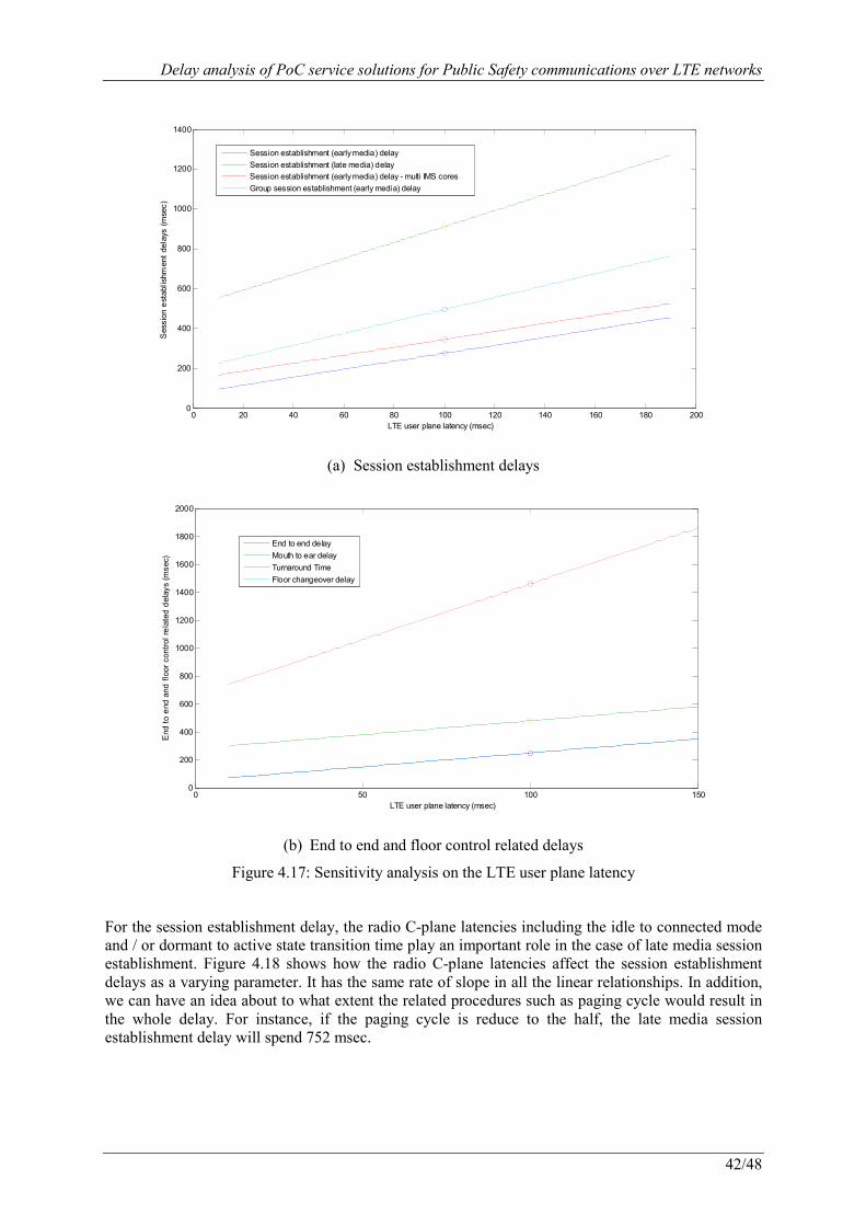
Delay analysis of PoC service solutions for Public Safety communications over LTE networks
42/48
0 20 40 60 80 100 120 140 160 180 2000
200
400
600
800
1000
1200
1400
LTE user plane latency (msec)
Session establishment delays (msec)
Session establishment (early media) delaySession establishment (late media) delaySession establishment (early media) delay - multi IMS coresGroup session establishment (early media) delay
(a) Session establishment delays
0 50 100 1500
200
400
600
800
1000
1200
1400
1600
1800
2000
LTE user plane latency (msec)
End to end and floor control related delays (msec)
End to end delayMouth to ear delayTurnaround TimeFloor changeover delay
(b) End to end and floor control related delays
Figure 4.17: Sensitivity analysis on the LTE user plane latency
For the session establishment delay, the radio C-plane latencies including the idle to connected mode and / or dormant to active state transition time play an important role in the case of late media session establishment. Figure 4.18 shows how the radio C-plane latencies affect the session establishment delays as a varying parameter. It has the same rate of slope in all the linear relationships. In addition, we can have an idea about to what extent the related procedures such as paging cycle would result in the whole delay. For instance, if the paging cycle is reduce to the half, the late media session establishment delay will spend 752 msec.
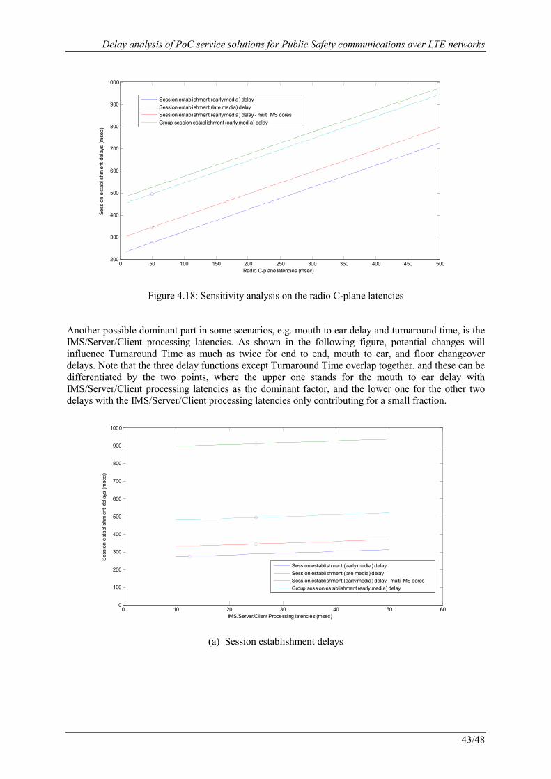
Delay analysis of PoC service solutions for Public Safety communications over LTE networks
43/48
0 50 100 150 200 250 300 350 400 450 500200
300
400
500
600
700
800
900
1000
Radio C-plane latencies (msec)
Session establishment delays (msec)
Session establishment (early media) delaySession establishment (late media) delaySession establishment (early media) delay - multi IMS coresGroup session establishment (early media) delay
Figure 4.18: Sensitivity analysis on the radio C-plane latencies
Another possible dominant part in some scenarios, e.g. mouth to ear delay and turnaround time, is the IMS/Server/Client processing latencies. As shown in the following figure, potential changes will influence Turnaround Time as much as twice for end to end, mouth to ear, and floor changeover delays. Note that the three delay functions except Turnaround Time overlap together, and these can be differentiated by the two points, where the upper one stands for the mouth to ear delay with IMS/Server/Client processing latencies as the dominant factor, and the lower one for the other two delays with the IMS/Server/Client processing latencies only contributing for a small fraction.
0 10 20 30 40 50 600
100
200
300
400
500
600
700
800
900
1000
IMS/Server/Client Processing latencies (msec)
Session establishment delays (msec)
Session establishment (early media) delaySession establishment (late media) delaySession establishment (early media) delay - multi IMS coresGroup session establishment (early media) delay
(a) Session establishment delays
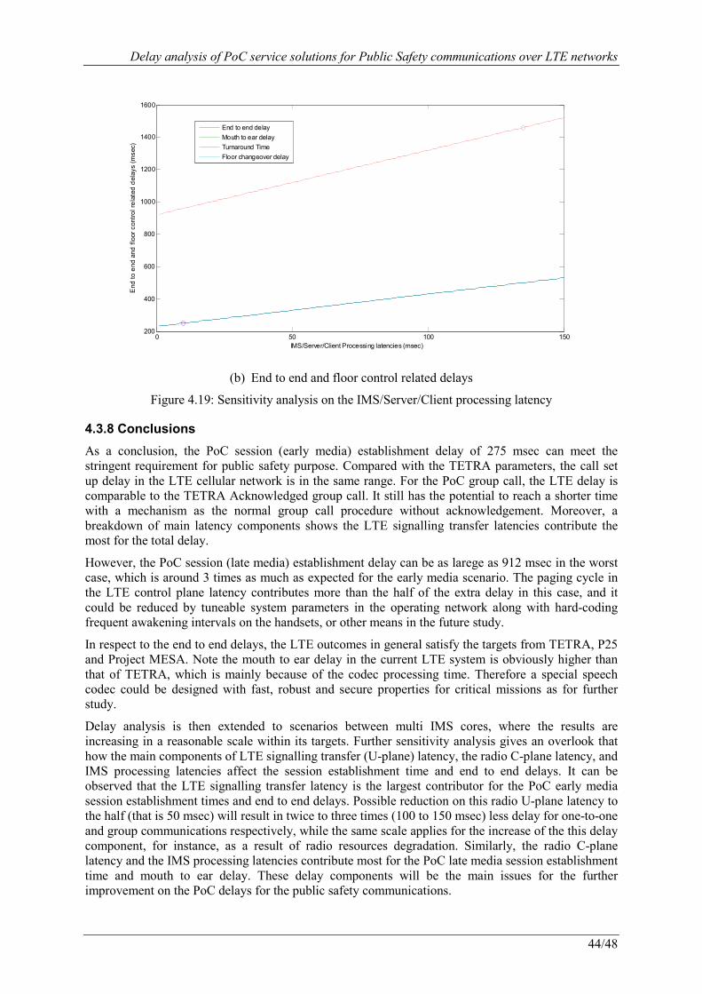
Delay analysis of PoC service solutions for Public Safety communications over LTE networks
44/48
0 50 100 150200
400
600
800
1000
1200
1400
1600
IMS/Server/Client Processing latencies (msec)
End to end and floor control related delays (msec)
End to end delayMouth to ear delayTurnaround TimeFloor changeover delay
(b) End to end and floor control related delays
Figure 4.19: Sensitivity analysis on the IMS/Server/Client processing latency
4.3.8 Conclusions
As a conclusion, the PoC session (early media) establishment delay of 275 msec can meet the stringent requirement for public safety purpose. Compared with the TETRA parameters, the call set up delay in the LTE cellular network is in the same range. For the PoC group call, the LTE delay is comparable to the TETRA Acknowledged group call. It still has the potential to reach a shorter time with a mechanism as the normal group call procedure without acknowledgement. Moreover, a breakdown of main latency components shows the LTE signalling transfer latencies contribute the most for the total delay.
However, the PoC session (late media) establishment delay can be as larege as 912 msec in the worst case, which is around 3 times as much as expected for the early media scenario. The paging cycle in the LTE control plane latency contributes more than the half of the extra delay in this case, and it could be reduced by tuneable system parameters in the operating network along with hard-coding frequent awakening intervals on the handsets, or other means in the future study.
In respect to the end to end delays, the LTE outcomes in general satisfy the targets from TETRA, P25 and Project MESA. Note the mouth to ear delay in the current LTE system is obviously higher than that of TETRA, which is mainly because of the codec processing time. Therefore a special speech codec could be designed with fast, robust and secure properties for critical missions as for further study.
Delay analysis is then extended to scenarios between multi IMS cores, where the results are increasing in a reasonable scale within its targets. Further sensitivity analysis gives an overlook that how the main components of LTE signalling transfer (U-plane) latency, the radio C-plane latency, and IMS processing latencies affect the session establishment time and end to end delays. It can be observed that the LTE signalling transfer latency is the largest contributor for the PoC early media session establishment times and end to end delays. Possible reduction on this radio U-plane latency to the half (that is 50 msec) will result in twice to three times (100 to 150 msec) less delay for one-to-one and group communications respectively, while the same scale applies for the increase of the this delay component, for instance, as a result of radio resources degradation. Similarly, the radio C-plane latency and the IMS processing latencies contribute most for the PoC late media session establishment time and mouth to ear delay. These delay components will be the main issues for the further improvement on the PoC delays for the public safety communications.
Delay analysis of PoC service solutions for Public Safety communications over LTE networks
45/48
5. Conclusion This master thesis work presents the concept of public safety communication solutions over 3GPP commercial cellular networks, and analyzes the feasibility on the key aspect of PoC delay budgets especially for the LTE and IMS systems.
First, the motivations and technical requirements of public safety communications using modern commercial cellular technologies are introduced and outlined. Second, the IMS-based public safety communication network architecture and the PoC service are presented with details. Third, a survey is made on the PoC delay targets in commercial mobile networks and for modern emergency communication systems from related literature. Then PoC session establishment times and end to end delays are estimated by calculating the latency components in IP-CAN and IMS network entities, following the analytical model developed from the guidelines from ITU-T.
As expected, the result shows that typical PoC session establishment (early media) time and end to end delay are within 275 milliseconds and 250 milliseconds respectively, which can satisfy the requirements for public safety purposes, and are similar as the delay parameters in trunked communication systems such as TETRA and P25. Moreover, PoC session establishment (late media) and group session establishment time, mouth to ear delay and Turnaround time, and floor changeover delay are also provided, and further extensions are done for delays between different IMS cores. However, PoC late media session establishment time is shown to be obviously higher than expected, and group session establishment time and mouth to ear delay are worse than TETRA targets to certain extent.
Finally, sensitivity analysis on the results indicates the possible influence from the variation of main delay components of LTE signalling transfer latency, the radio C-plane latency and IMS processing latencies. Correspondingly, improvements are proposed towards each of these contributors. Tuneable system parameters and hard-coding interval configurations on the public safety devices could reduce the paging cycle in the radio C-plane latency to lower down the PoC late media session establishment time. The research for a fast and robust speech codec can decrease the IMS processing latencies to help the mouth to ear delay to reach close to the TETRA range, and lower down the Turnaround Time in the mean time. The reduction on the LTE signalling transfer latency is for future study and may benefit from the evolution of the commercial cellular technology.
Future work can be carried out in the three aspects below:
· to improve the PoC delay performance, for instance, to implement multicast and/or broadcast mechanisms for PoC group communication, other means to reduce the paging cycle, and the proposals mentioned above;
-to extend the analysis addressed in this thesis through simulations at system level. This should allow assessing the impact of network load and location of group call participants within the coverage area on PoC performance;
· to continue further qualitative and quantitative comparison analysis between the PoC over LTE solution discussed in this thesis and any other potential native LTE feature that might be proposed by 3GPP to improve group communications as a result of current work items on device-to-device communication and enhanced group communication.
Delay analysis of PoC service solutions for Public Safety communications over LTE networks
46/48
6. References [1] Brenna Smith, Tom Tolman. Can We Talk, Public Safety and the Interoperability Challenge.
National Institute of Justice, 2000.
[2] National Task Force on Interoperability. Why Can't We Talk, Working Together To Bridge the Communications Gap To Save Lives. NTFI, 2003.
[3] ETSI EN 300 392-1, V 1.2.1 Terrestrial Trunked Radio (TETRA); Voice plus Data (V+D); Part 1: General network design, January 2003.
[4] http://www.project25.org
[5] http://www.tetrapol.com/home/tetrapol.html
[6] http://www.motorola.com/Business/US-EN/Business+Product+and+Services/Two-Way+Radios+and+Pagers+-+Business/iDEN+Harmony
[7] http://wwwen.zte.com.cn/en/solutions/wireless/gota/200812/t20081219_160250.html
[8] Mark Metcalf. Project MESA: advanced mobile broadband communications for public safety applications. Personal, Indoor and Mobile Radio Communications, 2003. PIMRC 2003. 14th IEEE Proceedings on. Sept, 2003.
[9] Electronic Communications Committee (ECC) within the European Conference of Postal and Telecommunications Administrations (CEPT). Public Protection and Disaster Relief Spectrum Requirements. ECC REPORT 102. Helsinki, January 2007.
[10] Rolf Blom, Peter de Bruin, Jesper Eman, Mats Folke, et al. Public Safety Communication Using Commercial Cellular Technology. The Second International Conference on Next Generation Mobile Applications, Services, and Technologies, 2008.
[11] Balachandran, K. Budka, K.C. Chu, T.P. Doumi, T.L. Kang, J.H. Mobile responder communication networks for public safety. IEEE Communications Magazine, Jan. 2006.
[12] Chao Chen, Pomalaza-Raez C., Colone M., Martin R., Isaacs J., Modeling of a Public Safety Communication System for Emergency Response. IEEE International Conference on Communications, 2009. ICC '09. June 2009.
[13] TETRA MoU Association. Push To Talk over Cellular (PoC) and Professional Mobile Radio (PMR). TETRA, 2004.
[14] Sanjay Kanti Das. Feasibility study of IP Multimedia Subsystem (IMS) based Push-to-Talk over Cellular (PoC) for Public Safety and Security communications. Master's Thesis, Department of Electrical and Communication Engineering, Helsinki University of Technology (HUT), 2006.
[15] Stefan Sundkvist. Public Safety Communication over 3GPP LTE. Master's Thesis, Department of Computer Science and Electrical Engineering, Luleå University of Technology, 2008.
[16] Miikka Poikselkä, Georg Mayer. The IMS: IP multimedia concepts and services (3rd edition). Wiley & Sons, cop. 2009.
[17] National Public Safety Telecommunications Council (NPSTC) Broadband Working Group. Mission Critical Voice Communications Requirements for Public Safety. Aug, 2011.
[18] 3GPP TS 36.201: Evolved Universal Terrestrial Radio Access (E-UTRA); LTE physical layer; General description, Release 10.
[19] Krishna Balachandran, Kenneth C. Budka, Thomas P. Chu, Tewfik L. Doumi, Joseph H. Kang, Robert Whinnery. Converged wireless network architecture for homeland security. Military Communications Conference, 2005. IEEE MILCOM 2005. Atlantic City, NJ, Oct. 2005.
Delay analysis of PoC service solutions for Public Safety communications over LTE networks
47/48
[20] 3GPP TD SP-120421. 3GPP™ Work Item Description: Group Communication System Enablers for LTE. June, 2012.
[21] US Dept. of Commerce. Public safety LTE. Presentation available at: http://3gpp.org/Future-Radio-in-3GPP-300-attend.
[22] ETSI TS 102 181 V1.1.1. Emergency Communications (EMTEL); Requirements for communication between authorities/organizations during emergencies. Dec, 2005.
[23] IPWireless. LTE addressing the needs of the Public Safety community. 3GPP RAN Workshop on Rel-12 and Onward RWS-120030. June, 2012.
[24] Javier Gozalvez. Long-Term Evolution FDD and TDD Demonstration. Vehicular Technology Magazine, IEEE. March, 2008.
[25] The SAFECOM Program - Department of Homeland Security. Statement of Requirements, Version 1.0. March, 2004.
[26] LEWP-RCEG (Radio Communication Expert Group of the Law Enforcement Working Party of the European Council), “Draft PPDR Applications Catalogue”, available at http://www.cept.org/Documents/fm-49/4618/FM49(12)001_PPDR-applications-catalogue
[27] IETF RFC 3261 “SIP: Session Initiation Protocol”.
[28] http://www.openmobilealliance.org/
[29] Open Mobile Alliance, Push to talk over Cellular (PoC) – Architecture, Version 2.0, Feb 2008.
[30] P. Kim, A. Balazs, E. van den Brock, et al. IMS-based Push-to-Talk over GPRS/UMTS. Wireless Communications and Networking Conference, 2005 IEEE. New Orleans, 2005.
[31] Comneon, Ericsson, Motorola, Nokia, Siemens. Push-to-talk over Cellular (PoC) Architecture; Release 2.0.
[32] IETF RFC 2616 “Hypertext Transfer Protocol”.
[33] IETF RFC 3550 “RTP: A Transport Protocol for Real-Time Applications”.
[34] Push to Talk over Cellular Requirements (Approved Version1.0 – 09 June 2006), Open Mobile Alliance, OMA-RD-PoC-V1_0-20060609-A.
[35] 3GPP2 S.R0100: Push-to-Talk over Cellular (PoC) System Requirements, Version 1.0. September, 2005.
[36] Comneon, Ericsson, Motorola, Nokia, Siemens. Push-to-talk over Cellular (PoC) User Requirements; Release 2.0.
[37] Push to Talk over Cellular Requirements (Approved Version 2.0 – 02 Aug 2011), Open Mobile Alliance, OMA-RD-PoC-V2_0-20110802-A.
[38] Peter Stavroulakis, TErrestrial Trunked RAdio – TETRA. Springer, 2007.
[39] TETRA MoU Association. Wireless Public Safety Communications Network - planning considerations. TETRA, June 2008.
[40] Motorola POSITION PAPER. Ensuring Resilience and Availability in a TETRA System. Jan, 2008.
[41] Analysys Mason. Report for the TETRA Association. Public safety mobile broadband and spectrum needs. March, 2010.
[42] ETSI TR 102 021-1: "Terrestrial Trunked Radio (TETRA); User Requirement Specification TETRA Release 2; Part 1: General Overview".
[43] ETSI TR 102 021-4: "Terrestrial Trunked Radio (TETRA); User Requirement Specification TETRA Release 2; Part 4: Air Interface Enhancements".
Delay analysis of PoC service solutions for Public Safety communications over LTE networks
48/48
[44] Office for Interoperability and Compatibility - Department of Homeland Security. Public Safety Statement of Requirements for Interoperability and Compatibility, Volumn II, Version 1.2. August, 2008.
[45] APCO Project 25 Statement of Requirements (P25 SoR). March 3, 2010.
[46] http://www.projectmesa.org/
[47] MESA TS 70.001: Project MESA; Service Specification Group - Services and Applications; Statement of Requirements (SoR) V3.3.1 (2008-03).
[48] 3GPP Liaison Statement S1-121247: Information about the system improvements requirements for the adoption of LTE for mission/business critical communications. May, 2012.
[49] REPORT ITU-R M.2135, Guidelines for evaluation of radio interface technologies for IMT-Advanced.
[50] REPORT ITU-R M.2134, Requirements related to technical performance for IMT-Advanced radio interface(s).
[51] 3GPP TR 36.912: Feasibility study for Further Advancements for E-UTRA (LTE-Advanced), Release 10.
[52] Siddharth Mohan, Rohit Kapoor, Bibhu Mohanty. Latency in HSPA Data Networks. Qualcomm corporation.
[53] Md. Ebna Masum, Md. Jewel Babu. End-to-End Delay Performance Evaluation for VoIP in the LTE network. Master's Thesis, Department of Telecommunication Systems, Blekinge Institute of Technology, 2011.
[54] 3GPP TS 23.203: Policy and charging control architecture, Release 11.
[55] 3GPP TR 25.903: Continuous connectivity for packet data users, Release 10.
[56] T. Eyers, H. Schulzrinne. Predicting Internet Telephony Call Setup Delay. In Proc. of IP Telephony Workshop, Apr. 2000.
[57] Erik Akerfeldt. Push-to-Talk over Cellular over High Speed Downlink Packet Access –A Performance Evaluation. Master of Science Thesis, Kungliga Tekniska Högskolan, 2005.
[58] Zhou Xing, Lu Meilian. Performance Evaluation of IMS-based Push-to-Talk Service over Multiple Wireless Access Networks. 5th International Conference on Wireless Communications, Networking and Mobile Computing, WiCom '09, Beijing, China, 2009.
[59] Open Mobile Alliance. OMA PoC System Description. OMA-TS-PoC_System_Description-V2_0-20110802-A.