delight lighting system guide - dimension … · lighting channels the delight controller contains...
TRANSCRIPT
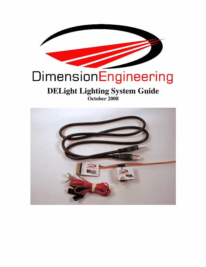
DELight Lighting System Guide October 2008

Attaching the DELight Controller
DELight plugs into your receiver and runs from BEC power. Odds are good that your
speed control’s built-in BEC isn’t sufficient to handle the current draw of the DELight
and attached lights; a separate receiver battery or a switching BEC will likely be required.
Control of the DELight depends on a signal input from your receiver. . Wires can be
soldered in parallel, or you can use a Y-connector to slave a DELight to the appropriate
receiver channel, but you must run it from one of your receiver channels, and that
channel will control the DELight. The channel can (and for many applications, should) be
used for its normal operation as well.
Trip Point and Control: DELight normally has two lighting patterns loaded per
channel. This can be as simple as “one is on and the other is off,” or as complex as fade
effect or morse code. Which program the controller uses is determined by the Trip Point
and the position of the channel it is put in parallel to.
This means that if the trip point is 50%, flipping an Aux switch set to ON, or increasing
throttle to be above 50%, or ailerons above 50%, etc, the pattern of lighting will change,
depending on whether you have it attached to your Aux, Thr or Ail.
A trip point will have a degree of Hysteresis if you have programmed it to do so (or are
using the default program). The actual trip point will be very slightly beyond the
percentage input that is set. For instance, if a trip point were 50% and hysteresis were
2%, the pattern wouldn’t change until the signal was above 52%, and after that, wouldn’t
change until below 48%.

A DELight connected in parallel to your throttle input will change programs based on the
position of your throttle stick. This is used in applications like afterburner effects.

A DELight connected in parallel to a servo channel will change programs based on that
servo input. This is handy if you want to make turn signals or the like.

A DELight connected to an auxiliary channel will change programs based on the position
of your aux switch (or aux dial).

Lighting Channels
The DELight Controller contains eight channels of LED light. Please note that the
Controller itself is only rated for 4A, even though the maximum rating of each
individual channel adds up to more than that. They are:
Channels 1-4: Current controlled and rated for up to 250mA. (Dimension LEDs are only
rated to 150 mA, however.) The LED will draw as much as it is programmed to draw and
receive whatever voltage is necessary to keep current at that level. Programmable for
brightness, both overall and as part of lighting sequences. If attaching non-Dimension
LEDs to it, a resistor is not required.
Channels 5-6: Non-current controlled and rated for up to 2A. Programmable for sequence
and useful as a switch. Non-Dimension LEDs will require resistors. Can be used to power
other applications as well, as the voltage on these channels is equal to the voltage at the
receiver.
Channels 7-8: Non-current controlled and rated for up to 2A. Not programmable;
anything connected to these channels will be on as long as the controller has power. Non-
Dimension LEDs will require resistors.
To determine what value resistor is needed for one of your LEDs on a non-current
controlled channel, there are many online calculators. www.led.linear1.org/led.wiz is a
fairly simple one.
Default Programming
The preset program on the DELight sets Channels 1-3 to be tail strobes that activate
above 75% of the corresponding input.
Channel 4 is initially dim, but hits full brightness at above 50% signal.
Channels 5 and 6 switch at 50%; channel 5 is on only below half signal, and channel 6 is
only on above it.

Installing LEDs in a Foam Wing
For installation on the wingtips of a foam plane, cut a channel in the front edge. A razor
blade or piece of sharpened aluminum will suffice.
Pace out the length of the pigtail over the course of the wing. There should be enough
wire; if not, soldering in extensions won’t cause problems.

A squeeze on the edges of the channel should help keep the wire from twisting.

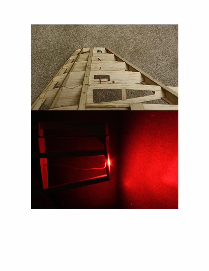
Installing LEDs in a Wood Frame Wing
Gently pry open the servo housings from the end of the LED’s pigtail. Use a pin, a pair of
tweezers or the like to lift the extrusions holding the wires in place.

Remove the wires from the housing so they can fit through as small a hole in the frame as
possible.
Drill a small hole in your frame (2.5mm diameter or so will do) and thread the wires
through it.

Cut a square hole at the end of the wingtip that the LED can fit through.
Two spots of adhesive on either side of the circuit board will keep the LED in place on
your wingtip.