deliverable 5-b: review and update on aura system
TRANSCRIPT

“Focusing on education, research, and development of technology to sense and understand natural and manmade environments."
“Meeting our transportation needs through innovative research, distinctive educational programs, technology transfer, and workforce development.”
Prepared By:
Michigan Tech Research Institute
and
Michigan Tech Center for Technology & Training
of
Michigan Technological University
Deliverable 5-B: Review and
Update on AURA System Requirements, Sensors, and
Platforms – Supplemental Report
Michigan Technological University
Characterization of Unpaved Road Condition Through the Use of
Remote Sensing Project Submitted version of:
April 20, 2016
Authors: Colin Brooks, [email protected]
Richard Dobson, [email protected]

Review and Update on AURA System Requirements, Sensors, and Platforms – Supplemental Report 2
This page is intentionally blank.

Review and Update on AURA System Requirements, Sensors, and Platforms – Supplemental Report iii
Table of Contents
Section I: Introduction .................................................................................................................................. 5
Section II: Fixed-wing UAVs ....................................................................................................................... 6
Lehman LP-960 ........................................................................................................................................ 6
Sensefly eBee ............................................................................................................................................ 9
Section III: Fixed-Wing Data and Results .................................................................................................. 10
Section IV: Comparison between a Fixed-wing System and Multi-rotor System for Unpaved Roads Analysis ...................................................................................................................................................... 14
Data Collection and Camera ................................................................................................................... 14
Processing Fixed-wing Data through RSPS ............................................................................................ 14
Distress Detection ................................................................................................................................... 15
Section V: Conclusion ................................................................................................................................ 16

Review and Update on AURA System Requirements, Sensors, and Platforms – Supplemental Report iv
List of Figures
Figure 2-1: Lehman LP-960 wing and ground control station. ..................................................................... 6
Figure 2-2: Lehmann LP-960 being hand launched and manually controlled. ............................................. 7
Figure 2-3: Mission planning with the Lehman ground control software. .................................................... 8
Figure 2-4: Final flightpath for the proposed collect of Piotter Hwy near Britton, MI. ............................... 9
Figure 2-5: Sesnsefly eBee (Photo Courtesy of Jarlath O'Neil-Dunne, University of Vermont) ................. 9
Figure 2-6: Hand launching of an eBee (Photo Courtesy of Jarlath O'Neil-Dunne) ................................... 10
Figure 3-1: Detail of potholes on an unpaved road from the West Haven, VT. The orthoimage and DEM were generated in Pix4D and the hillshade was generated in ArcGIS from the DEM. ............ 12
Figure 3-2: Detail of potholes on an unpaved road in Shelburne, VT. The orthoimage and DEM were generated in Pix4D and the hillshade was generated in ArcGIS from the DEM. Both the orthoimage and DEM are processed to a resolution of 3.3cm. ................................................. 13
Figure 4-1: A comparison between the level of detail between DEMs generated from the Hexacopter system and an eBee. Both hillshade representations are at the same scale and the pothole pointed out in the eBee hillshade is 67cm in width. ................................................................. 16
List of Tables
Table 4-1: DEM resolution requirements by distress. ................................................................................ 15
Table 4-2: Comparison of Detection ability between the eBee and Hexacopter systems. .......................... 16

Review and Update on URCAS Requirements, Sensors, and Platforms 5
Section I: Introduction
This report is supplemental to Deliverable 5-B “Review and Update on URCAS Requirements, Sensors, and Platforms” which reviewed and updated the requirements of the Aerial Unpaved Road Assessment (AURA) system, formerly known as URCAS. The initial system requirements were determined in Deliverable 1-A (Requirements for Assessment, published October 2011). With the system being developed based on recommendations defined in Deliverable 4-A (Sensor Selection, published in May 2011) and Deliverable 5-A (Platform Selection, published June 2012), additional information has been needed as the project developed. These reports led to the development of a multi-rotor based system carrying a high-resolution DSLR that could create centimeter-level resolution 3D models of road surfaces that were automatically processed into an XML location-tagged file output of density and severity of distresses.
The AURA system was developed around flying two 100ft (30m) sections which would represent one mile (1.6km) of road for assessing condition based on the Unsurfaced Road Condition Index (URCI) developed by the U.S. Army. This method is more suited to the rapid deployment of a multi-rotor system which is capable of vertical takeoff and landings and slow flying speeds. Another condition which was more suited to a multi-rotor system is the use of a DSLR camera which exceeds the payload capability of current lower cost fixed-wing platforms.
Since defining this method of data collection, there has been interest in collecting longer segments of unpaved roads. While current FAA regulations limit UAV operations to within line of sight (approximately ½ mile or 0.8 km) and below 122m / 400ft, this method would be a better adapted with reduced flying restrictions on distance. Fixed-wing UAVs are capable of longer flight times but are limited by payload capability and takeoff and landing constraints vs. multi-rotor systems. This report will evaluate the use of a fixed-wing UAV system for the collection of unpaved roads condition data to be processed through AURA’s Remote Sensing Processing Software (RSPS) developed earlier in the project for creation of the 3D road surfaces and automated road distress detection.

Review and Update on AURA System Requirements, Sensors, and Platforms – Supplemental Report 6
Section II: Fixed-wing UAVs
Fixed-wing UAVs are available in a variety of sizes and capabilities. These range in size from small hand launched varieties like the eBee to the larger catapult launched types. For rapid deployment assessment of unpaved roads and for operating in smaller areas, hand launched UAVs were focused on. Due to their small size and payload capability these UAVs are generally restricted to carrying only point and shoot cameras with lower resolution sensors and smaller lenses.
The major advantage of fixed wing UAVs is that they have longer flight time when compared to multi-rotor systems. They are usually powered by a single motor as opposed to four or more on multi-rotors. They are also more efficient in with respect to staying aloft. Multi-rotor systems have to be continuously creating downforce greater than their weight through their propellers to maintain flight. Fixed-wing UAVs only have to create enough force to push it through the air while the wings create the lift. This requires significantly less power to accomplish and therefore greater flying times with smaller batteries.
Lehman LP-960
The Lehman LP-960 is a fixed-wing UAV owned by Michigan Tech with a flying wing design and has a wingspan of 1m and 0.5m long (3ft and 1.5ft respectively) and weighs 1250g ready-to-fly with a camera (Figure 2-1). Depending on what “extras” it is purchased with (such as extra batteries), it costs approximately $10,000 (the base kit is currently €6990 or about $7940 at current exchange rates from its European manufacturer). It has an endurance of up to 25 minutes and can fly in winds up to 25kt (29mph). It is designed to carry a maximum payload capacity is 350g (12oz) which Lehmann recommends as Sony point and shoot cameras or a GoPro. The camera is triggered by the LP-960 using an infrared (IR) remote mounted over the cameras sensor and captures imagery at one frame per second.
Figure 2-1: Lehman LP-960 wing and ground control station.

Review and Update on AURA System Requirements, Sensors, and Platforms – Supplemental Report 7
The UAV is hand launched (Figure 2-2) and can be remotely piloted or fly pre-programmed GPS-based waypoints. During takeoff the LP-960 needs roughly 30m / 100ft from the launch point to stabilize and ascend to an altitude which is over nearby trees or other obstacles which could be near the launch site. When using the waypoint capability, after launch the LP-960 ascends to the desired altitude and then flies to the starting waypoint. After the mission is complete, the LP-960 flies to towards the designated landing point. The motor shuts off manually which initiates a landing in which the UAV would glide in to land. A clearing which is at least 90m / 300ft long is needed for landing safely.
Figure 2-2: Lehmann LP-960 being hand launched and manually controlled.
The LP-960 is designed to carry Sony point and shoot cameras such as the Sony NEX-5T with a 16MP resolution, Sony a6000 with a 24MP sensor, and the Canon PowerShot S110 with a 12MP sensor (the Michigan Tech team has the Sony NEX-5T, which Lehmann Aviation described as their preferred sensor). The highest image ground piexel resolution possible at an altitude of 55m / 180ft by the Sony NEX-5T is 1.3cm, the Sony a6000 is estimated to be less than 0.9cm and the Canon PowerShot S110 is 2cm. Actual resolution will depend on the ability of the UAV to maintain its altitude as wind will impact its flying characteristics and quality of the imagery. The Digital Elevation Model (DEM) derived using the RSPS typically has a maximum resolution of twice the resolution of the input (i.e., images with 2 cm ground pixel resolution have the possibility of being turned into a 3D DEM model with 4 cm x,y,z resolution). This is done as a method to minimize processing time while still achieving accurate models of the road surface, and not exceeding the resolution capabilities of the collected imagery.

Review and Update on AURA System Requirements, Sensors, and Platforms – Supplemental Report 8
The waypoint capability is limited to a “mow-the-lawn” collection style. This is where the operator designates an area to be surveyed and the OperationCenter software (that comes with the LP960) calculates the flight path needed to complete the survey with overlapping imagery (Figure 2-3). Flying altitude is determined by the software based on an imagery resolution selection and type of camera flown. In the example below the camera is a Sony NEX-5T set to a 16mm focal length and a desired ground pixel resolution of 1.6cm. The flying altitude for this collection would be roughly 55m / 180ft. The collection area is set to a wide area over the unpaved road since the software is using Google Earth for the background imagery, and the georeferencing of Google’s product can be off by several meters (the Michigan Tech team has seen Google Earth imagery be displaced from its true location by 10m / 33ft in some locations). This wider area but still focused collection area enables full collection of the road while allowing for some error in the Google imagery as well as some inaccuracy from the GPS on the UAV itself.
Figure 2-3: Mission planning with the Lehman ground control software.
After the parameters of the collect are entered into the OperationCenter software, the flightpath is calculated. Figure 2-4 shows the final collection flightpath. The takeoff and landing points can be moved to the desired location free of trees and other obstacles. For the example mission at Piotter Hwy (a previous study location for this project), the LP-960 flies at an altitude of 55m and make three flight lines over the area of interest and captures 444 imagers. The estimated time to complete this collect from takeoff to landing is just over 11 minutes. An adjustable “No Fly Zone” is also included around the flight area. This designates a boundary at which the UAV will not pass during the flight to focus its data collection area.

Review and Update on AURA System Requirements, Sensors, and Platforms – Supplemental Report 9
Figure 2-4: Final flightpath for the proposed collect of Piotter Hwy near Britton, MI.
Sensefly eBee
The Sensefly eBee is a flying wing design similar to the Lehmann LP-960 (Figure 2-5). Sensefly is another European company and part of the Parrot group. It has a 1m wingspan and weighs 730g (1.6lbs). It has an endurance of up to 40 minutes and can fly in winds up to 24kt (28mph or 44kph). It is designed to carry point and shoot cameras and can operate with the Sony WX220 (18MP) or the Canon PowerShot S110 (12MP). An option for the eBee is RTK (Real Time Kinematic) GPS capability for increased positional accuracy of imagery location tagging. The cost of an eBee RTK is $51,000 with 3D processing software.
Figure 2-5: Sesnsefly eBee (Photo Courtesy of Jarlath O'Neil-Dunne, University of Vermont)
Review and Update on AURA System Requirements, Sensors, and Platforms – Supplemental Report 10
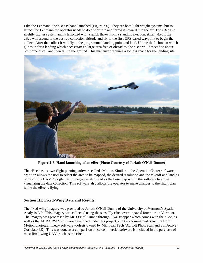
Like the Lehmann, the eBee is hand launched (Figure 2-6). They are both light weight systems, but to launch the Lehmann the operator needs to do a short run and throw it upward into the air. The eBee is a slightly lighter system and is launched with a quick throw from a standing position. After takeoff the eBee will ascend to the desired collection altitude and fly to the first GPS-based waypoint to begin the collect. After the collect it will fly to the programmed landing point and land. Unlike the Lehmann which glides in for a landing which necessitates a large area free of obstacles, the eBee will descend to about 6m, force a stall and then fall to the ground. This maneuver requires a lot less space for the landing site.
Figure 2-6: Hand launching of an eBee (Photo Courtesy of Jarlath O'Neil-Dunne)
The eBee has its own flight panning software called eMotion. Similar to the OperationCenter software, eMotion allows the user to select the area to be mapped, the desired resolution and the takeoff and landing points of the UAV. Google Earth imagery is also used as the base map within the software to aid in visualizing the data collection. This software also allows the operator to make changes to the flight plan while the eBee is flying.
Section III: Fixed-Wing Data and Results
The fixed-wing imagery was provided by Jarlath O’Neil-Dunne of the University of Vermont’s Spatial Analysis Lab. This imagery was collected using the senseFly eBee over unpaved four sites in Vermont. The imagery was processed by Mr. O’Neil-Dunne through Pix4Dmapper which comes with the eBee, as well as the AURA RSPS software developed under this project, and two commercial Structure from Motion photogrammetry software toolsets owned by Michigan Tech (Agisoft PhotoScan and SimActive Correlator3D). This was done as a comparison since commercial software is included in the purchase of most fixed-wing UAVs such as the eBee.

Review and Update on AURA System Requirements, Sensors, and Platforms – Supplemental Report 11
Each of these photogrammetry software packages uses the same Structure from Motion algorithms to generate a 3D point cloud. The main difference between them is the amount of user input needed and allowed in the processing. An example of this is in the “point cloud densification” step. Both PhotoScan and Pix4D allow the user to select various levels, with the least detailed being roughly eight times the input imagery resolution to the highest being equal to the input imagery. The reason for adding this option is that there is a tradeoff between final point cloud / DEM resolution and the amount of time needed to process the imagery. For the RSPS developed under this project, the point cloud densification is roughly twice the input imagery resolution resulting in DEMs with a resolution of 1cm from the current AURA system. This resolution could be changed in the RSPS but it would have to be changed in the core programming as it is not currently an option for the user to change for a dataset. Likewise, Correlator3D does not allow for the user to change this setting.
In the example from the Westhaven, VT data collection in which the imagery was processed through Pix4D, the output DEM resolution from Pix4D is 84cm (33 inches). There is a series of potholes visible in the original imagery which has a ground sample distance of 13cm (5”). With a diameter of the potholes being 30-61cm (12-24”), they are not represented in the DEM and therefore cannot be detected and analyzed with the distress detection algorithms. Figure 3-1 shows the comparison between the Orthoimage, DEM and Hillshade of the group of potholes. Over the entire length of the road surface there were 26 potholes visible in the orthoimage but due to the low DEM resolution, none of them could be identified through AURA RSPS automated software. Alternatively the Agisoft reconstruction of the same area was not able to produce accurate results because of the low imagery resolution and was not able to be evaluated.

Review and Update on AURA System Requirements, Sensors, and Platforms – Supplemental Report 12
Figure 3-1: Detail of potholes on an unpaved road from the West Haven, VT. The orthoimage and
DEM were generated in Pix4D and the hillshade was generated in ArcGIS from the DEM.
Another dataset which was captured at 3.3cm resolution and the DEM was processed at an equal resolution to the imagery using Pix4D and out of 19 potholes in the scene, one of them is visible in the DEM (Figure 3-2). This pothole is 67cm / 26in diameter and 10cm / 4in deep while the other two beside it in the orthoimage are smaller.

Review and Update on AURA System Requirements, Sensors, and Platforms – Supplemental Report 13
Figure 3-2: Detail of potholes on an unpaved road in Shelburne, VT. The orthoimage and DEM were generated in Pix4D and the hillshade was generated in ArcGIS from the DEM. Both the
orthoimage and DEM are processed to a resolution of 3.3cm.

Review and Update on AURA System Requirements, Sensors, and Platforms – Supplemental Report 14
Section IV: Comparison between a Fixed-wing System and Multi-rotor System for Unpaved Roads Analysis
Data Collection and Camera
There are currently two methods for collecting unpaved roads data; 1. flying an entire mile of road or 2. The method developed under this project, which involved collecting two representative sections per mile. For both methods, a fixed-wing UAV would collect data along the entire mile, as it would be more practical with its flying characteristics. Using the example shown earlier with the proposed collect with the Lehmann over a one mile stretch of Piotter Hwy, the data collection would take 11.1 minutes from takeoff to landing. Both systems would take off and land from the center of the one mile section to ensure that the UAV platforms remain within line of sight.
For the collection of the same one mile section of Piotter Hwy, the Bergen Hexacopter (used in the current AURA system) would need 16.5 minutes for takeoff, data collection of the entire one mile section, and landing. By comparison, the collection of two representative sections (each section being 100ft / 30.5m) of road would require just 5 minutes from takeoff to landing. Also by flying representative sections, the Hexacopter could evaluate three miles (4.8km) of unpaved roads on a single set of batteries.
During data collection, the camera mounted on the Hexacopter is stabilized by a 2-axis gimbal. The gimbal counters roll and pitch movements of the hexacopter while in flight so that the camera is always pointed at nadir. The hexacopter itself is stabilized through a GPS IMU (Internal Measurement Unit). The GPS is used to hold the UAV’s x, y, and z position when there is an absence of inputs given by the controller, as well as to fly programmed waypoints. The IMU keeps the hexacopter level while in flight and provides input for the gimbal. As a mission is being flown, wind gust will tend to push the hexacopter off course and the GPS IMU will correct this action by changing the roll orientation to maintain a straight flight path. This action is corrected by the gimbal to keep the camera pointed at nadir.
Fixed-wing UAVs like the eBee also have a GPS IMU but they do not have a gimbal to stabilize the camera. Like the multi-rotor systems, the eBee will automatically adjust its orientation to maintain the flight path programmed by the operator. As the UAV is being buffeted around by gusting winds and correcting for those actions, the camera is moving with the aircraft without any correction. Depending on the severity of the wind gust, the camera is sometimes quickly jerked while a picture is being taken. Since it is not mounted to a gimbal this could cause motion blurring is some frames.
The type of camera used on the UAV also makes a difference in the quality of imagery. Larger multi-rotor systems like the Bergen Hexacopter can carry a DSLR while the eBee is restricted to smaller point and shoot cameras. There are differences in sensor and lens quality as well as operational differences between the two camera types. The Nikon D800 currently used on the AURA allows for full manual operation. Prior to a collect, the operator manually sets the camera shutter speed, aperture and focus to ensure properly exposed imagery while minimizing motion blur with the lighting conditions during the flight. Some point and shoot cameras have limited capability with full manual settings as well as setting the focus. Point and shoot cameras on fixed-wing systems typically are set to shutter priority and auto focus. This could lead to image blurring issues as light conditions change leading to the aperture changing, leading to changes in depth-of-field. The auto focus feature could cause blurring issues as it will tend to focus on larger objects such as tree tops, buildings or other parts of the image area and not always the road surface. Depending on the depth-of-field and where the camera is focusing in the field of view, the road surface may be out of focus and therefore blurred.
Processing Fixed-wing Data through RSPS
The imagery from Shelburne, VT was processed through RSPS first as it is the best example imagery collected via fixed wing with the highest resolution and having a pothole represented in the DEM. The

Review and Update on AURA System Requirements, Sensors, and Platforms – Supplemental Report 15
dataset provided was collected with a Canon PowerShot S110 camera at an altitude of 136 meters (446 ft), resulting in images covering an area of 29,625m2 (7.3 acres). Given the resolution provided by the 12 megapixel sensor, the best images in this dataset have a ground sample distance (GSD) of 5 centimeters. The horizontal and vertical accuracy of any 3D models would therefore have minimum errors of 5 cm.
The automated unpaved road distress classification portion of RSPS takes a 3D mesh and road width value as inputs and enumerates 4 distress classes (ruts, corrugation, crown, potholes) and their respective severities in an XML document. It operates on the assumption that the unpaved road is located in a topographically dynamic area that may contain vegetation, where the road is the most topographically uniform region in the scene. It also assumes that the road is straight and of a constant width. At runtime, the distress classification algorithm identifies the road in the 3D model by calculating entropy masking the model where the entropy exceeds a threshold value. After extracting the road, it classifies and measures defects according the scale implied by the road with value specified.
The unpaved road in the provided dataset is bounded by manicured and landscaped lawns. Because the distress classification algorithm depends on topographic entropy to differentiate the road from its surroundings, it misclassified much of the lawn area as part of the unpaved road. When classifying defects in this larger, smoother region, the algorithm was unable to correctly measure identifiable defects due to the scale implied by the specified road width measurement. The other dataset were not processed through RSPS the 3D modeling portion reduces the output DEM resolution to twice the input imagery (i.e., 3.3 cm ground imagery becomes at least a 6.6cm x.y,z resolution DEM at best). The DEMs created from the other dataset with this point cloud densification setting did not model distresses as they were either lower than the DEM resolution or the DEM was not accurate enough to represent them.
Distress Detection
As defined in Deliverable 1-A, each distress requires the system to achieve a ground sample distance of at least 1” (2.5cm) in order for the RSPS to quantify the distresses as defined early in the project as meeting the needs of unpaved road managers. Table 4-1 shows that the DEM resolution of the AURA system should be at least 2.5cm (x,y, and z) for the detailed classification of distresses. With the reduction of the DEM resolution to twice that of the input imagery the Bergen Hexacopter and Nikon 800 currently has a resolution of 1cm.
Table 4-1: DEM resolution requirements by distress.
By using the imagery form the Shelburne, VT eBee collect the output resolution of the DEM is 6.6cm / 2.6in. With this DEM resolution a condition assessment would not be able to categorize potholes into the 5.1cm depth categories. It is also not able to measure crown, rutting or corrugation into the 2.5cm categories. The DEMs also contained considerably much more error in z-axis reconstruction than imagery collected form the hexacopter. Table 4-2 displays the estimated minimum size of distress each platform is able to detect as based on the imagery provided.
DistressMinimum DEM Resolution (cm)
Comment
Crown 2.5 z-axisPothole Diameter 10.2 x and y axisPothole Depth 5.1 z-axisRutting Diameter 10.2 x and y axisRutting Depth 2.5 z-axisCorrugation 2.5 z-axis
Review and Update on AURA System Requirements, Sensors, and Platforms – Supplemental Report 16
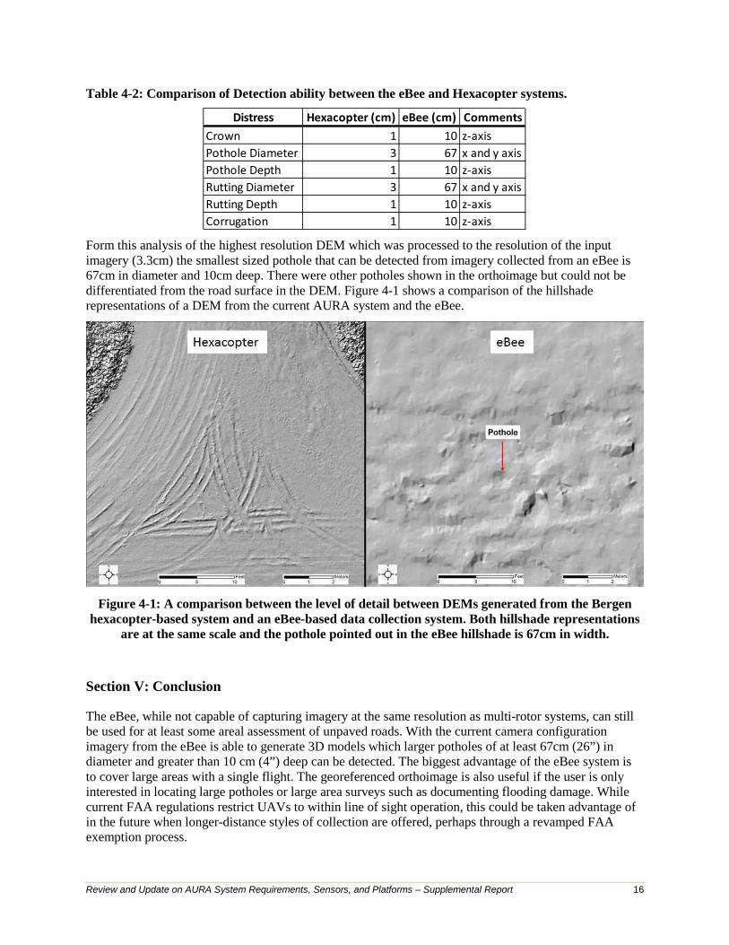
Table 4-2: Comparison of Detection ability between the eBee and Hexacopter systems.
Form this analysis of the highest resolution DEM which was processed to the resolution of the input imagery (3.3cm) the smallest sized pothole that can be detected from imagery collected from an eBee is 67cm in diameter and 10cm deep. There were other potholes shown in the orthoimage but could not be differentiated from the road surface in the DEM. Figure 4-1 shows a comparison of the hillshade representations of a DEM from the current AURA system and the eBee.
Figure 4-1: A comparison between the level of detail between DEMs generated from the Bergen
hexacopter-based system and an eBee-based data collection system. Both hillshade representations are at the same scale and the pothole pointed out in the eBee hillshade is 67cm in width.
Section V: Conclusion
The eBee, while not capable of capturing imagery at the same resolution as multi-rotor systems, can still be used for at least some areal assessment of unpaved roads. With the current camera configuration imagery from the eBee is able to generate 3D models which larger potholes of at least 67cm (26”) in diameter and greater than 10 cm (4”) deep can be detected. The biggest advantage of the eBee system is to cover large areas with a single flight. The georeferenced orthoimage is also useful if the user is only interested in locating large potholes or large area surveys such as documenting flooding damage. While current FAA regulations restrict UAVs to within line of sight operation, this could be taken advantage of in the future when longer-distance styles of collection are offered, perhaps through a revamped FAA exemption process.
Distress Hexacopter (cm) eBee (cm) CommentsCrown 1 10 z-axisPothole Diameter 3 67 x and y axisPothole Depth 1 10 z-axisRutting Diameter 3 67 x and y axisRutting Depth 1 10 z-axisCorrugation 1 10 z-axis

Review and Update on AURA System Requirements, Sensors, and Platforms – Supplemental Report 17
If the user is interested in detailed analysis of the unpaved roads, such as distress detection down to an inch / 2.5 cm, the current multi-rotor version of the AURA system is the best option. With the ability to carry a high resolution DSLR the system can create DEMs with a 1cm (0.4”) resolution. With current FAA regulations restricting UAVs to within line of sight operation, both the eBee and the Bergen Hexacopter are capable of collecting a one mile road segment.
An alternative to the eBee fixed-wing system is the Tempest fixed wing UAV aircraft from UASUSA (http://www.uasusa.com/products-services/aircraft/the-tempest.html). It has the capability to fly a 4.5kg (10 lbs) payload for up to 1.5 hours. While larger than the eBee (3m or 9.8ft wingspan), it is still easily transported with removable wings and is still hand-launched. The major advantage of this system is that it is capable of carrying the high-resolution Nikon D800 payload that is currently used by the AURA system to evaluate sub-inch road distresses. This would allow for centimeter / sub-inch 3D reconstructions of the unpaved roads from a fixed-wing UAV. This ability would be extremely useful when new regulations allow for beyond line of sight operations as it could collect high resolution imagery over several miles of road in a single flight; a linear data collection distance of at least 40 miles / 64 km has been estimated, with 60 miles / 97 km possible.
Additionally, the RSPS will have to be adapted so that end users can either take advantage of its full functionality (3D processing and distress detection) or just the distress detection. Since most fixed-wing UAVs come with 3D processing software with an easy-to-use interface, it is most likely that the distress detection component will be the most useful on a commercial basis. Currently, the AURA RSPS software is a single piece where the user defines the image location and a few parameters and all the processing is automated. Adapting this to use other inputs could be done either by either making it an option to feed in a point cloud or DEM generated by other software (such as Pix4D, Photoscan, or Correlator3D) into the current RSPS software, or making the distress detection component a standalone piece of software that can be licensed to companies offering AURA services. Both of these options are being explored with companies that have expressed interest in offering AURA-based road condition assessment services on a commercial basis.