demand duo systems operation & installation manual
TRANSCRIPT
Demand Duo Systems
Operation & Installation Manual

Rinnai 2 HW Demand Duo Systems OIM
Congratulations on the purchase of your Rinnai Demand Duo System. We trust you will have many years of comfort and enjoyment from your appliance.
IMPORTANT
BEFORE USING THIS APPLIANCE
Before proceeding with the operation or installation read this manual thoroughly and gain a full understanding of the appliance, to ensure safe and correct use.
IMPORTANT NOTICE FOR INSTALLERS
Please leave these instructions with the end user after commissioning of the system and alert the end user of the content sections "Warnings and "Periodic Inspection" and "Maintenance".
Not suitable as a pool or spa heater.
This manual must be read and understood before installation, commissioning and operation of water heaters and flue systems are attempted. The information contained in other Operating / Installation instructions supplied with water heaters applies in full, unless otherwise dictated in this manual.This appliance must be installed in accordance with:
• Manufacturer’s Installation Instructions
• Current AS/NZS 3000, AS/NZS 3500, AS/NZS 5601
• Plumbing Code of Australia (PCA)
• Local Regulations and Municipal Building Codesincluding local OH&S requirements
This appliance must be installed, maintained and removed ONLY by an Authorised Person.
For continued safety of this appliance it must be installed and maintained in accordance with the manufacturer’s instructions.
W169SAI Global
W208SAI Global
All Rinnai gas products sold in Australia
are A.G.A. certified.

Rinnai 3 HW Demand Duo Systems OIM
TABLE OF CONTENTS
Warnings & Safety 4
Regulatory Information ....................................................................................................................................................... 4
Notice to Victorian Consumers .......................................................................................................................................... 5
Safety .................................................................................................................................................................................... 5
Scald Hazards ...................................................................................................................................................................... 6
Important Information 7
Safety Devices ..................................................................................................................................................................... 7
Care & Maintenance 8
Installation Instructions 10
Regulations ........................................................................................................................................................................ 10
Appliance Location ............................................................................................................................................................ 10
HD28E, HD250E, HD210E (External models) ................................................................................................................... 10
HD28I, HD210I (Internal models) .......................................................................................................................................11
Horizontal Obstructions .....................................................................................................................................................11
Horizontal Flue Terminal Clearances (Extract from AS/NZS 5601) ............................................................................... 12
Co-Axial Flueing for Internal Models ............................................................................................................................... 13
Multiple Flue Terminals ..................................................................................................................................................... 14
Installation Options ........................................................................................................................................................... 15
Assembly ............................................................................................................................................................................ 16
Specifications 20
Installation Handover Manual 31
Cold Water Supply ............................................................................................................................................................. 31
Hot Water Outlet ............................................................................................................................................................... 31
Return Pump ������������������������������������������������������������������������������������������������������������������������������������������������������������������� 31Gas Supply ���������������������������������������������������������������������������������������������������������������������������������������������������������������������� 31Electrical Supply �������������������������������������������������������������������������������������������������������������������������������������������������������������� 31
Filling Instructions ............................................................................................................................................................. 32
Starting Instructions .......................................................................................................................................................... 32
Demand Duo Principle of Operation ................................................................................................................................ 32
Thermostatic Controller Operation .................................................................................................................................. 33
Demand Duo Preventative Maintenance ......................................................................................................................... 33
Tank ��������������������������������������������������������������������������������������������������������������������������������������������������������������������������������� 33Primary Pump ����������������������������������������������������������������������������������������������������������������������������������������������������������������� 33
Heavy Duty (HD) Heat Source ........................................................................................................................................... 34
Flue Length Dipswitches - REU-VCM .............................................................................................................................. 34
Ringmain Pump ................................................................................................................................................................. 36
Service ................................................................................................................................................................................ 36
Details ................................................................................................................................................................................. 37
Commercial Hot Water System Commissioning Check-List ......................................................................................... 37
Contacts 40

Rinnai 4 HW Demand Duo Systems OIM
READ ALL INSTRUCTIONS BEFORE USING THE APPLIANCE.Always comply with the following precautions to avoid dangerous situations and to ensure optimum performance.Failure to carefully read and follow all instructions in this manual can result in equipment malfunction, property damage, personal injury and/or death.DANGER: Indicates an imminently hazardous situation which, if not avoided, will result in personal injury or death.WARNINGS: Indicates a potentially hazardous situation which, if not avoided, could result in personal injury or death.CAUTIONS: Indicates a potentially hazardous situation which, if not avoided, could result in minor or moderate injury or damage to the appliance. It may also be used to alert against unsafe practices.
WARNING
REGULATORY INFORMATIONThis appliance shall be installed in accordance with these instructions and all regulatory requirements which exist in your area including those in relation to manual lifting, working at heights and on roofs. Applicable publications and regulations may include:
• AS/NZS 3500 National Plumbing and Drainage, AS/NZS 3000 Wiring rules, AS/NZ 5601 Gas Installations & Building Codes of Australia (BCA)
• Local Occupational Health and Safety (OH&S) regulations
• Local Regulations and Municipal Building CodesDO NOT operate this system before reading the manufacturers instructions. This appliance must be installed, commissioned and serviced by an authorised person in accordance with all applicable local rules and regulations.For continued safety of this appliance it must be installed, operated and maintained in accordance with the manufacturer’s instructions.This appliance is heavy, use 2 people or mechanical lifting device. Improper lifting may result in serious injury.DO NOT modify the electrical wiring of this appliance. If the control power wiring is damaged or deteriorated then it must be replaced only by an authorised person. Failure to do so may result in electric shock, fire, serious injury or product failure.Care should be taken not to touch the pipe work as it may be HOT!DO NOT place articles on or against this appliance.DO NOT store chemicals or flammable materials near this appliance.DO NOT operate with panels, covers or guards removed from this appliance.DO NOT remove covers while power is on.DO NOT enclose this appliance.DO NOT activate pump unless cylinder is full of water.Not suitable as a pool or spa heater.All Rinnai Demand Duo (DD) systems and components are Watermark Certified by SAI Global as applicable.The Rinnai DD1 model is certified as a gas storage water heater by the Australian Gas Association (AGA).AGA Certification applies to DD1 models only. AGA Certification does not apply to other DD models in this manual.All dimensions referred to in these instructions are in millimetres, unless otherwise specified.
NOTE
A NOTE ON ILLUSTRATIONS
The illustrations used in this manual are for explanatory purposes only and the shape of your unit may vary slightly from that which is shown in this manual.
IMPORTANT
WARNINGS & SAFETY

Rinnai 5 HW Demand Duo Systems OIM
WARNING
MANDATORY INSPECTION PRIOR TO INSTALLATION
Immediately report any damage or discrepancies to the Supplier of the appliance. This appliance was inspected and tested at the time of manufacture and packaging, and released for transportation without known damage. Upon receipt, inspect the exterior for evidence of rough handling in shipment. Ensure that the appliance is labelled correctly for the gas and electrical supply, and/or other services it is intended to be connected to.
For safety and warranty purposes, appliances that may be damaged or incorrect must not be installed or operated under any circumstances. Installation of damaged or incorrect appliances may contravene local government regulations. Rinnai disclaims any liability or responsibility whatsoever in relation to the installation or operation of damaged or incorrect appliances.
NOTICE TO VICTORIAN CONSUMERS
WARNING
This appliance MUST be installed by a person licensed with the Victorian Building Authority.ONLY a licensed person will have insurance protecting their workmanship.Make sure you use a licensed person to install this appliance and ask for your Compliance Certificate. For further information contact the Victorian Building Authority on 1300 815 127
SAFETY
WARNING
This appliance is NOT intended for use by persons (including children) with reduced physical, sensory or mental capabilities, or lack of experience and knowledge unless they have been given supervision or instruction concerning use of the appliance by a person responsible for their safety.
Children should be supervised to ensure that they DO NOT play with the appliance.
Any power leads from the water heater system components MUST be plugged into an external weatherproof electrical outlet. If the power supply cord of the system is damaged, it MUST be replaced by an authorised person in order to avoid a hazard, using genuine replacement parts available from Rinnai. Take care of not to touch the power plugs with wet hands.
If the supply cord is damaged, it must be replaced by the manufacturer, its service agent or similarly qualified persons in order to avoid a hazard.
DO NOT touch the unit cover or the flue outlet.
DO NOT insert objects into the flue outlet.
DO NOT spray water directly into the flue outlet.
Keep, trees, shrubs, etc. well clear of the flue outlet.
On colder days steam may discharged from the flue outlet. This condition is normal for high efficiency appliances and does not indicate a fault.
DO NOT Spray aerosols in the vicinity of this appliance while it is in operation.
DO NOT use or store flammable materials in or near this appliance.
DO NOT place articles on or against this appliance.
DO NOT modify this appliance.
DO NOT store pool chemicals near this appliance.
HOT!
WARNINGS & SAFETY

Rinnai 6 HW Demand Duo Systems OIM
Hydrogen Gas
If the hot water heater is not used for two weeks or more, a quantity of hydrogen gas, which is highly flammable, may accumulate in the water heater. To dissipate this safety, it is recommended that a non electrically operated hot tap be turned on for several minutes at a sink, or bath, but not a dishwasher or other appliance. During this procedure there must be no smoking, open flame or any electrical appliance operating nearby. If hydrogen gas is discharged through the tap, it will probably make a sound like air escaping.
Water Temperature
To meet regulatory requirements the temperature of stored water MUST NOT be less than 60°C. The temperature controller is factory pre-set to 65°C. The outlet temperature setting of the gas continuous flow heater is factory pre-set to 75°C.
WARNING
This appliance may deliver water at high temperature. Refer to the Plumbing Code of Australia (PCA), local requirements and installation instructions to determine if additional delivery temperature control is required.
WARNINGThe temperature controller setting must only be adjusted by suitably qualified trades person.
SCALD HAZARDS
Hot Water can cause scalds.
Children, disabled, and the elderly are at the highest risk of being scalded.
Feel water temperature before bathing or showering.
Scalds from hot water taps can result in severe injuries to young children.
Scalds can occur when children are exposed directly to hot water when they are placed into a bath which is too hot.
Always......
Test the temperature of the water with your elbow before placing your child in the bath, also carefully feel water before bathing or showering yourself.
Supervise children whenever they are in the bathroom.
Make sure that the hot water tap is turned off tightly.
Consider.....
Installing child proof tap covers or child resistant taps (both approaches will prevent a small hand being able to turn on the tap).
Installing tempering valves or thermostatic mixing valves which reduce the hot water temperature delivered to the taps. Your local plumbing authority may already require that these be fitted. Contact your installer or local plumbing authority if in doubt.
Never….
Leave a toddler in the care of another child. They may not understand the need to have the water temperature set at a safe level.
DANGER BEWARE OFSCALDING HAZARDS
WARNINGS & SAFETY

Rinnai 7 HW Demand Duo Systems OIM
SAFETY DEVICES
For safe operation this water heater is fitted with a combination Pressure & Temperature Relief Valve, a temperature controller and an over-temperature cut out on each heater.
WARNING
DO NOT tamper with or remove safety devices.
DO NOT operate this water heater unless all safety devices are fitted and in working order.
The operation of the thermal cut out indicates a possibly dangerous situation. DO NOT reset the thermal cut out until the water heater has been serviced by a qualified person.
Pressure & Temperature Relief (PTR) Valve
This valve is located near the top of the storage tank and is essential for safe operation.
WARNING
DO NOT seal or block the outlet of the PTR valve or its drain pipe.
DO NOT replace the PTR valve with one that has a higher pressure rating than is specified for the water heater.
The PTR valve should be checked for performance or replaced at intervals not exceeding 5 years, or more frequently in areas with a high incidence of water deposits by a qualified person. The easing gear must be operated at least once every six months or more frequently in areas with a high incidence of water deposits.
WARNING
Failure to do this may result in the water heater cylinder failing or under certain circumstances, exploding. Water discharged will be very hot. Exercise care to avoid scald injury. If the valve does not seal again when the easing gear is closed, contact Rinnai to arrange inspection by a qualified person.
It is important you raise and lower the easing gear gently. If the valve does not discharge water when the easing gear lever is lifted, there may be a serious problem and the power supply to the system must be switched off immediately. Contact Rinnai to arrange inspection by a qualified person.
It is normal for the PTR valve to release a small quantity of water through the drain pipe during heating. If the valve dribbles or leaks continuously, try easing the valve gear for a few seconds. This may dislodge any foreign matter and stop leakage. If leakage does not stop there may be a problem as detailed below:
• If there are heavy flows of water until the water heater is cold which then stops until the water reheats there may be a serious problem and the power supply to the system must be switched off immediately. Contact Rinnai to arrange inspection by a qualified person.
• If there is a steady flow for long periods, often at night, it may be as a result of the water pressure exceeding the design pressure of the water heater. Contact your installing plumber as a Pressure Limiting Valve (PLV) may be required.
Expansion Control Valve (ECV)
An ECV is recommended in all geographical areas where the water supply has a tendency to cause scaling, including South Australia and Western Australia. Local regulatory authorities may require that an ECV be fitted. The ECV is to be supplied and fitted by the installer. Refer to the section Water Quality for more information on scaling water.
If an ECV is fitted, operate the easing gear at least once every six months to remove any deposits and to verify that it is not blocked.
The ECV should be checked for performance or replaced at intervals not exceeding 5 years, or more frequently in areas with a high incidence of water deposits by a qualified person.
It is normal and desirable that the ECV allows a small quantity of water to be discharged through the drain pipe during the heating cycle. If the valve dribbles or leaks continuously, operate the easing gear for a few seconds. This may dislodge any foreign matter and stop leakage. If leakage does not stop Contact Rinnai to arrange inspection by a qualified person.
Gently lift lever until water flows from drain line, lower lever gently
to close
IMPORTANT INFORMATION

Rinnai 8 HW Demand Duo Systems OIM
WATER QUALITY
The water quality of most public supplies is suitable for the water heating system. The water quality from bore wells is generally unsuitable for the water heating system. Refer to the ‘Warranty Conditions’ for water quality parameters and how they affect the warranty conditions. If in doubt about the water quality, have it checked against the parameters listed in the warranty conditions. If sludge or foreign matter is present in the water supply, a suitable strainer filter should be incorporated in the water supply to the system.
DRAINING
WARNING
Draining MUST be carried out by a qualified person.
Water may be HOT during draining.
Drain the storage tank(s) as follows:1. Isolate or turn ‘OFF’ the water heater at the electricity supply.2. Close the cold water isolation valve at the inlet to the storage tank(s).3. Close the water isolation valve at the return port from the gas water heater(s) on the storage tank(s).4. Close the hot water isolation valve at the outlet of the storage tank(s).5. Operate the PTR valve easing gear - gently. Operating the PTR valve easing gear will relieve the pressure
in the water heater.6. Undo the cold water inlet union. Attach a hose to the water heater side of the union. Let the other end of the
hose go to a drain.7. Operate the PTR valve easing gear again. This allows air into the water heater and will result in water draining
through the hose.
PERIODIC MAINTENANCE & SERVICING
Rinnai service network personnel are fully trained and equipped. If your Rinnai appliance requires servicing contact Rinnai as per the details on the back page of this manual. Rinnai recommends that this commercial appliance be inspected and serviced by a qualified person every 12 months.
If overflow tray and drain are fitted, it is the users responsibility to have these checked periodically to ensure there are no blockages.
The user should operate the easing gear of the ECV and PTR valve (if fitted) every 6 months as described under “Safety Devices” on page 7.
The pressure and temperature relief valve and expansion control valve MUST be checked for performance or replaced by an authorised person at intervals not exceeding 5 years or more frequently in areas where the water is classified as scaling water (see ‘Water Quality’).
If the electric conduit, power supply cord or plug to hot water system is damaged, they MUST be replaced by an authorised person in order to avoid a hazard. The power supply cord and plug must be replaced by a genuine replacement part available from Rinnai.
CARE & MAINTENANCE

Rinnai 9 HW Demand Duo Systems OIM
SAVE A SERVICE CALL
Check the items below before requesting a service. Service and parts charges may be incurred where it is found that there is no fault with the water heater and the issue is related to the plumbing installation or is due to the failure of water or electric supplies.
Insufficient or no hot waterIs the electricity supply connected?
Check that the isolating switch marked “HOT WATER” or “WATER HEATER” at the meter box is switched on. Check also that any isolating switches installed near the water heater are switched on.Check the fuse or circuit breaker marked “HOT WATER” or “WATER HEATER” at the meter box. Repeated failure of fuse or tripping of circuit breaker indicates a fault which must be investigated by an authorised trades person.
Is there insufficient gas supply for gas heater(s)?
Check gas is available and turned ‘ON’.Check the isolation valve in the gas line is opened.Refer to your plumber to ensure the gas line has been purged of air after installation.
Are you using more hot water than you think?
Often end users are surprised at the amount of hot water used, especially when showering. If the amount of hot water used during the day exceeds the storage capacity of the hot water system, it is likely that there will be insufficient hot water. Has your plumber install water saving fixture and/or flow control or pressure limiting valves to reduce consumption.
Thermostat settings? Check the temperature of hot water delivered with a thermometer placed under the closest outlet (usually the kitchen sink) on a non-tempered hot water line.The temperature of the water delivered should be at least 55°C (allowing for heat losses in pipe work).If this is not the case, the temperature may need to be increased. Contact your installer or Rinnai to discuss adjusting the thermostat.
No water from the hot tap? Restriction in the hot tap or failure of the cold water supply to the heater.Check for water flow at the other hot taps and that the cold water isolation valve is fully open.
Is the Primary Pump operating correctly?
Check the controller screen information to verify the primary pump is operational relative to the tank temperature set point. Use the maintenance function for the controller to test the pump operation. Refer to separate manual for controller functionality.
Is the controller showing an error?
Refer to separate manual for the controller functionality.
Are the cold water filters clean on the gas water heater(s)?
Isolate and remove the water filter at the cold water connection point. Refer to separate manual for the gas continuous flow water heater operation.
CARE & MAINTENANCE

Rinnai 10 HW Demand Duo Systems OIM
These instructions apply to the Demand Duo (DD) range of Rinnai hot water systems ranging from one Heavy Duty continuous flow water heater coupled with one storage tank up to 12 heavy Duty continuous flow water heaters coupled with multiple tanks:
REGULATIONS
For continued safety of this appliance it must be installed, operated and maintained by authorised person in accordance with manufacturer’s instructions, current with AS/NZS 3500 and AS/NZS 5601, local regulations and municipal building codes.
Rinnai Demand Duo hot water systems are not suitable or approved as pool heater.
Read these instructions carefully before proceeding with the installation.
APPLIANCE LOCATION
Ensure reasonable access for installation, servicing and removal. All valves, controls and pumps etc must be easily accessible.
Rinnai Demand Duo tanks and any free standing frames must be mounted on a solid level base, capable of supporting the weight of the appliance when full of water. Ensure components are not allowed to stand in water. Spacers under the tank are recommended in wet areas.
All Rinnai Demand Duo tanks are "left handed" with the water connections to the left when viewing the thermistor housing from the front.
These systems are combined with Rinnai HD series, HD28e (VCM2837WC), HD28i (VCM2837FFUC), HD250e (VRM3237WC), HD210e (N3237WC) and HD210i (N3237FFC).
Rinnai HD units are fan assisted appliances and thus have lower clearances than a natural draft appliance of the same MJ rating.
HD28E, HD250E, HD210E (EXTERNAL MODELS)
This appliance is designed for ‘Outdoor’ Installation only. As such, it must be located in an above ground open air situation with natural ventilation, without stagnant areas, where gas leakage and products of combustion are rapidly dispersed by wind and natural convection.
This appliance must be mounted on a vertical structure with the water and gas connections on the underside pointing downwards. For appliances installed on elevated structures or under floors specific requirements apply. Refer to AS/NZS 5601 Section 6 for details.
This appliance must not be used as a domestic spa or swimming pool heater.
Location of the appliance flue terminal must be in accordance with Section 6 and Figure 6.2 of AS/NZS 5601. Figure 6.2 is reproduced in the ‘Horizontal Flue Terminal Clearances’ section of these instructions.
NOTE
AS/NZS 5601 is current at the time of printing. It is the installers’ responsibility to ensure current requirements are met.
INSTALLATION INSTRUCTIONS

Rinnai 11 HW Demand Duo Systems OIM
HD28I, HD210I (INTERNAL MODELS)
This appliance is designed for ‘Indoor’ installation only. It may be installed ‘Outdoors’ in an enclosure if the requirements of AS/NZS 5601 Section 6 are satisfied. An enclosure is defined as a compartment, enclosed are of partitioned off space primarily used for the installing of the appliance.
If installed in an enclosure either Internally or Externally, the location should be ventilated to allow gas to dissipate and provision must be made for the safe disposal of any leaking water to a visible location.
This appliance must not be used as a domestic spa or swimming pool heater.
Two types of flue systems are available:
• The Rinnai Commercial Common Flue System.
• The Rinnai Co-Axial FFU flue system.
The use of non Rinnai flue components may result in a dangerous situation and violates regulations.
The appliance(s) must be located so that the flue terminal exits the building at a suitable point.
For detailed information refer to “FLUEING FOR INTERNAL MODELS” on page 13.
This appliance must be located so that the flue terminal exits the building at a suitable point.
If a horizontal (wall) terminal is used, the location must be in accordance with Section 6 and Figure 6.2 of AS/NZS 5601. Figure 6.2 is reproduced under ‘HORIZONTAL FLUE TERMINAL CLEARANCES’ on page 12 of this manual.
If a vertical (roof) terminal is used, the location must be in accordance with Section 6 of AS/NZS 5601 and the ‘FLUEING FOR INTERNAL MODELS’ on page 12.
HORIZONTAL OBSTRUCTIONS
AS/NZS 5601-2010 ‘Gas Installations’ stipulates a minimum horizontal clearance of 500mm between a building structure and obstruction facing the terminal.
For Rinnai External continuous flow water heaters such a building structure must ‘obstruct’ the full front cover height of the appliance, or extend vertically above and below the front cover.
There must be no partial obstructions to the front cover of the appliance or any other parts of the appliance casing. This will avoid the appliance failing to operate under windy conditions.
500mm
INSTALLATION INSTRUCTIONS

Rinnai 12 HW Demand Duo Systems OIM
HORIZONTAL FLUE TERMINAL CLEARANCES (EXTRACT FROM AS/NZS 5601)
Min. Clearances (mm)
For appliances up to 50 MJ/h input 200300For appliances over 50 MJ/h input 300500
300300* ecafrus rehto ro ynoclab a evoba ,dnuorg eht morFb300500* renroc lanretxe ro llaw nruter a tnorFc
dFrom a gas meter (M) (see Note 5)(see Clause 5.11.5.9 for vent terminal location of regulator)(see Table 6.7 for New Zealand requirements)
10001000
e From an electricity meter or fuse box (P) † (see Note 5) 500500epip lios ro epip niard a morFf
g Horizontally from any building structure* = or obstruction facing a terminal 500500h From any other flue terminal , cowl, or combustion air intake * 300500
Appliances up to 150 MJ/h input * 300500Appliances over 150 MJ/h input up to 200 MJ/h input * 3001500Appliances over 200 MJ/h input up to 250 MJ/h input * 5001500Appliances over 250 MJ/h input * 15001500All fan-assisted flue appliances, in the direction of discharge 1500-
10001500rewolb aps a gnidulcni ,telni ria lacinahcem a morFk
Space heaters up to 50 MJ/hr inputOther appliances up to 50 MJ/hr input 500500Appliances over 50 MJ/h input and up to 150 MJ/h input 10001000Appliances over 150 MJ/h input 15001500
metI.feR
aBelow eaves, balconies and other projections:
FIGURE 6.2 (in-part) LOCATION OF FLUE TERMINALS OF BALANCED FLUE,ROOM-SEALED, FAN-ASSISTED OR OUTDOOR APPLIANCES
n
j
Horizontally from an openable window, door, non-mechanical air inlet, or any other opening into a building with the exception of sub-floor ventilation:
Vertically below an openable window, non-mechanical air inlet, or any other opening into a building with the exception of sub-floor ventilation:
Where dimensions c, j or k cannot be achieved an equivalent horizontal distance measureddiagonally from the nearest discharge point of the terminal to the opening may be deemed bythe Technical Regulator to comply. See Clause 6.9.4 for restrictions on a flue terminal under a covered area.See Figure J3 for clearances required from a flue terminal to an LP Gas cylinder. Aflue terminal is considered to be a source of ignition.For minimum clearances not addressed above acceptance should be obtained from the Technical Regulator.Minimum clearances d and e also apply to any combustion air intake openings of appliances.
1
23
4
5
* Unless appliance is certified for closer installation.† Prohibited area below electricity meter or fuse box extends to ground level. NOTES:
75150
Shading indicates prohibitedarea for f lue terminals
LEGEND:
I = Mechanical air inletS = Structure
M = Gas meterT = Flue terminal
P = Electr ic ity meter or fuse boxZ = Fan-assisted appliance only
Direct ion ofdischarge
See Note 1See Note 1
Opening intoa bui lding
T
TT
T
T
T
T
C
M
dde
e
hj
j
j
n
b
f
a
h
P
ZS
k
k
g
gg
I
T
Door
Fan assistedNatural draft
150150
INSTALLATION INSTRUCTIONS

Rinnai 13 HW Demand Duo Systems OIM
CO-AXIAL FLUEING FOR INTERNAL MODELS
This system is certified and suitable for use with Rinnai internal commercial continuous flow water heaters.
The Rinnai Flueing system must be installed in accordance with the instructions supplied with the flue terminal. Non Rinnai flueing systems MUST NOT be used.
The Rinnai internal flueing system is highly versatile and makes installation of an internal water heater simple and convenient.
The flueing for internal water heaters is a Co-Axial design. It is manufactured from an aluminium or propylene inner flue pipe to discharge product of combustion and a thermoplastic outer pipe for air supply to the appliance. The water heater is a room sealed appliance.
NOTE: Each Rinnai water heater is flued individually.
Horizontal flueing can be used as a direct wall flue or extended from another internal wall.
Vertical flueing is used when the water heater needs to be flued vertically through the roof.
A condensate trap may be required for extended flue runs depending on the type of water heater. Details are provided in the separate flue installation instructions and MUST be adhered to.
Rinnai HD internal water heaters are classified as ‘room sealed’ appliances. Flue systems must be installed in accordance with Rinnai Installation Instructions (supplied with flue terminals), local gas fitting regulations, municipal building codes, AS/NZS 5601 and all other relevant statutory regulations.
The flue terminal clearances in AS/NZS 5601 do not apply to the HD28e, HD250e, or HD210e heaters installed side by side. These appliance are AGA certified to be located side by side, for both internal an external models
DD6 Direct Wall Flue
DD5 typical installation
INSTALLATION INSTRUCTIONS

Rinnai 14 HW Demand Duo Systems OIM
NOTE
Only Rinnai Flueing systems can be used with Internal Water Heaters. Non-Rinnai Flueing systems are not certified and will not be covered under warranty.
For all further information on Internal Flueing, please refer to separate Flueing manual supplied with Flueing components.
MULTIPLE FLUE TERMINALS
Dimension 'H' in AS/NZS 5601 Figure 6.2 does not apply when multiple Rinnai external water heaters of the same model are installed on the same vertical face with flue terminals at the same height. Under these conditions appliances can abut each other as shown below:
Before commencing installation, ensure you refer to the content of all other Operation / Installation manuals supplied with the appropriate model Rinnai Continuous Flow Water Heater or Rinnai Flueing Systems.
INSTALLATION INSTRUCTIONS

Rinnai 15 HW Demand Duo Systems OIM
INSTALLATION OPTIONS
The Rinnai Commercial Common Flue System is suitable for the Rinnai Internal Commercial Gas Continuous Flow Water Heaters (listed on the cover of this manual) in accordance with the flue design options outlined in the AS/NZS 5601.1 Appendix titled ‘Flue Design'. Figure 1 & Figure 2 below, illustrate typical application principles.Figure 1. Typical Natural Draft Flue Installation - VRM/VCM-Series ONLY
Figure 2. Typical Power Flue Installation - Both N-Series & VRM/VCM-Series
NOTE
For more information on the flue system, please refer to the Rinnai Commercial Common Flue System Operation & Installation Manual.
RINNAI FLUE HEADER(S)
NATURAL DRAFT FLUE PIPESUPPLIED BY OTHERS/ALREADY INSTALLED
CERTIFIED FLUE COWL
CONDENSATE DRAINWHERE NECESSARY
RINNAI ADJUSTABLE SLEEVE/OR EQUIVALENT
MULTIPLE RINNAI WATER HEATERS
ROOF
RINNAI COMMON FLUEINSERT TERMINAL
ENDCAPA FALL TOWARDS THEDRAIN IS REQUIRED
FAN FAILURE SENSING DEVICE INTERLOCKED WITHGAS SUPPLY TO APPLIANCES
FANDAMPER ADJUSTINGDILUTION AIR
MULTIPLE RINNAI CONTINUOUS FLOW WATER HEATERS
EXTERNAL WALLEXTERNAL WALL
FLUE PIPE SUPPLIED BY OTHERS / ALREADY INSTALLED
RINNAI FLUE HEADER(S)
EXHAUST OF DILUTED COMBUSTION AIR.INTAKE OF FRESH AIR
PLANT ROOM VENTILATIONAND COMBUSTION AIR
RINNAI COMMONFLUE INSERT TERMINAL
RINNAI ADJUSTABLE SLEEVE / BEND OR EQUIVALENT
(Note 1) A FALL TOWARDS THE
DRAIN IS REQUIRED
CONDENSATE DRAINWHERE NECESSARY
INSTALLATION INSTRUCTIONS

Rinnai 16 HW Demand Duo Systems OIM
UNPACKING INTEGRATED STORAGE UNIT WITH ONE GAS HEATER (DD1)
Remove outer cardboard box. Remove screws attaching feet on tank to wooden pallet. Carefully remove system from pallet and inspect for any transport damage. Ensure that PTR valve and brass plug 32mm supplied in box is located and stored. DO NOT install if any components are damaged.
UNPACKING SYSTEMS WITH MULTIPLE HEATERS
Tank:
Remove outer cardboard box.
Carefully remove tank from pallet and inspect for any transport damage. Ensure that PTR valve, supplied in box is located and stored. DO NOT install if any components are damaged.
Manifold of HD water heaters:
With cardboard box in upright position, remove packing straps and slide lid upwards. Remove water heater and frame assembly carefully and place upright in desired location. Repeat this for all manifold modules you have received that are necessary to build the complete system. DO NOT install if any components are damaged
ASSEMBLY
Integrated storage unit with one gas heater (DD1)
• Position tank in desired position.
• Attach PTR valve supplied in box to 20mm port at top of tank. As for the DD1 28e / 28i 250L or 315L, plug off second port with 20mm plug supplied. For DD1 250e/210e/210i 250L or 315L, attach another PTR valve to second port at the top of tank.
• Plug off second cold inlet port at the bottom of the tank with 32mm plug supplied with tank.
• Run PTR valve drains to suitable discharge position.
Demand Duo 2 – Demand Duo 10
A Rinnai Demand Duo is supplied in modules. The storage tank(s) are separate and the heat source is made up of either 2 or 3 HD continuous flow units plumbed in parallel and mounted on a dedicated and lightweight frame. Standard systems are connected together by coupling the barrel unions supplied with the copper header pipes. Specifically engineered systems (generally for larger projects or restrictive plant areas) will be marked up accordingly to aid the assembly process.
1
2
3
1
2
3
Gas
Hot Water
Cold Water
INSTALLATION INSTRUCTIONS

Rinnai 17 HW Demand Duo Systems OIM
Wall mounting or floor mounting of the heat source is possible.
Wall mounting - drill holes in the wall in the desired location and mount the frame to the wall using suitable fixings. A useful nominal height is 1500mm (height of the frame) from floor level. This is subject to site requirements, the desired location of the flue terminal in reference to AS/NZS5601 (page 12) and service accessibility. If you are installing an internal plant, flue design and the associated wall or roof penetrations need to be considered as the centre distance between the heaters varies depending on which heater is being installed. Refer to the drawings and specifications section from page 27 for dimensional information.
Floor mounting - you will require the appropriate number of DDBASE to enable suitable floor mounting. DDBASE requires some minor assembly using the brackets and fixings provided. Every module of either 2 or 3 heaters requires one DDBASE and it is recommended to assemble the DDBASE to the heat source module(s) prior to joining the pipework. The heat source can also be installed in a back to back configuration using DDFJOINKIT.
Again if you are installing an internal plant, flue design and the associated wall or roof penetrations need to be considered as the centre distance between the heaters varies depending on which heater is being installed. Refer to the drawings and specifications section from page 27 for dimensional information.
NOTE
When direct flueing through the wall that the water heaters are mounted on, it may be necessary to attach flue to water heater and push it through the wall before attaching the water heater to the wall.
Specifically engineered systems mounted on a skid base do not require any assembly of the heat source unless it has been split purely for transport purposes. If this is the case the pipe connections will be marked up accordingly to aid the assembly process.
The tank(s) and the primary pump must be installed as close as possible to the heat source to minimise pipe runs. A Demand Duo PLUS system comes complete with the primary pump mounted underneath the water heaters which allows the tank(s) to be very close to the heat source.
You may have a horizontal tank with your system and this is installed in exactly the same way as a standard vertical tank. Each port on the tank is suitably marked to identify the cold inlet, hot outlet and return outlet from the heat source. Refer to page 26 for details about the horizontal tank
External systems are provided with a weather cover and it is very important to mount this over the primary pump(s) to protect the electrical box form being exposed to wet weather.
You will note that some systems have a single primary pump, and some have dual primary pumps. This is dependant on the water heater and whether redundancy of the primary pump has been specifically requested. The system controller will be factory set to control the primary pumps to alternate every 12 hours (for redundancy purposes) or to work in unison (to suit certain water heaters). The system controller is mounted underneath one of the heat source modules and this module should be installed closest to the tank(s).
Optional Base(DDBASE)
INSTALLATION INSTRUCTIONS

Rinnai 18 HW Demand Duo Systems OIM
Ensure primary pump(s) are plugged into the controller and the controller is plugged into an available Socket Outlet. Socket Outlets will need to be provided to match the product you are installing. If you have a Demand Duo then Socket Outlets will need to be provided for all water heaters and controllers. If you have a Demand Duo PLUS then only one Socket Outlet per row of heaters will need to be provided.
Once you have completed the assembly of the system you are ready to connect it up to the building plumbing. DO NOT turn any power onto the system until you are at the commissioning stage. Refer to commissioning instructions and log as the back of this manual. Refer to Figure 3 to Figure 6 for assembly instructions.
Figure 3. Demand Duo
Figure 4. Demand Duo (Additional Tank)
Cold Water Supply
Install provided relief valves ensuring they are the
correct pressure rating
Hot Water Out
Primary Pump Flow Direction
Additional heat source module(s)
depending on system size
Heat source module with
mounted controller
Thermistor Wiring
Pipes & fittings by installer
● Socket Outlets for each water heater and the temperature controller MUST BE provided by the installer.● Additional tanks can be used and MUST BE suitably plumbed with balanced pipework as indicated.● Ensure the thermistor is securely fitted to the well in the tank.● Ensure primary pump(s) are securely plugged into the temperature controller and NOT plugged directly into a Socket Outlet
Cold Water Supply
Install provided relief valves ensuring they are the
correct pressure rating
Hot Water Out
Primary Pump Flow Direction
Additional heat source module(s)
depending on system size
Heat source module with
mounted controller
Thermistor Wiring
Pipes & fittings by installer
● A Socket Outlet for each water heater and the temperature controller MUST BE provided by the installer.● Additional tanks can be used and MUST BE suitably plumbed with balanced pipework as indicated.● Ensure the thermistor is securely fitted to the well in the tank.● Ensure primary pump(s) are securely plugged into the temperature controller and NOT plugged directly into a Socket Outlet
INSTALLATION INSTRUCTIONS

Rinnai 19 HW Demand Duo Systems OIM
Cold Water Supply
Install provided relief valves ensuring they are the
correct pressure rating
Hot Water Out
Primary Pump Flow Direction
Additional heat source module(s)
depending on system size
Heat source module with
mounted controller
Thermistor Wiring
Pipes & fittings by installer ● One Socket Outlet for each row of water heaters MUST BE provided by the installer. For example, a single row of heaters requires one Socket Outlet whilst a back to back system (two rows of heaters) require two Socket Outlets.● Additional tanks can be used and MUST BE suitably plumbed with balanced pipework as indicated.● Ensure the thermistor is securely fitted to the well in the tank.● Ensure the primary pump(s) are securely plugged into the temperature controller and NOT plugged directly into a Socket Outlet.
Plug the power lead
supplied into a
suitable Socket Outlet
Cold Water Supply
Install provided relief valves ensuring they are the
correct pressure rating
Hot Water Out
Primary Pump Flow Direction
Additional heat source module(s)
depending on system size
Heat source module with
mounted controller
Thermistor Wiring
Pipes & fittings by installer ● One Socket Outlet for each row of water heaters MUST BE provided by the installer. For example, a single row of heaters requires one Socket Outlet whilst a back to back system (two rows of heaters) require two Socket Outlets.● Additional tanks can be used and MUST BE suitably plumbed with balanced pipework as indicated.● Ensure the thermistor is securely fitted to the well in the tank.● Ensure primary pump(s) are securely plugged into the temperature controller and NOT plugged directly into a Socket Outlet.
Plug the power lead
supplied into a
suitable Socket Outlet
Figure 5. Demand Duo PLUS
Figure 6. Demand Duo PLUS (Additional Tank)
INSTALLATION INSTRUCTIONS

Rinnai 20 HW Demand Duo Systems OIM
DD1 Models, Drawing and SpecificationsAll Dimensions are (mm)
DD Model PTR Inclusions
Primary pump
MJ Rating (HD Water
Heater)Total System Weight (kG)
Fittings
Hot Cold PTR Gas
DD1 28e/ 250 ext
2 * HT 575 (46 kW)
UPS20 - 60N 210 110 RP1 1/4”
(32mm)*RP1 1/4” (32mm)
RP 3/4” (20mm)
RP 3/4” (20mm)
DD1 210e 250 ext
2 * HT 575 (92 kW)
UPS32 - 100N 209 125 RP1 1/4”
(32mm)*RP1 1/4” (32mm)
RP 3/4” (20mm)
RP 3/4” (20mm)
DD1 28e/ 315 ext
2 * HT 575 (46 kW)
UPS20 - 60N 210 120 RP1 1/4”
(32mm)RP1 1/4” (32mm)
RP 3/4” (20mm)
RP 3/4” (20mm)
DD1 28i/ 250 int
2 * HT 575 (46 kW)
UPS20 - 60N 210 110 RP1 1/4”
(32mm)*RP1 1/4” (32mm)
RP 3/4” (20mm)
RP 3/4” (20mm)
DD1 210e 315 ext
2 * HT 575 (92 kW)
UPS32-100N 209 125 RP1 1/4”
(32mm)*RP1 1/4” (32mm)
RP 3/4” (20mm)
RP 3/4” (20mm)
DD1 28i/ 315 int
2 * HT 575 (46 kW)
UPS20 - 60N 199 210 RP1 1/4”
(32mm)RP1 1/4” (32mm)
RP 3/4” (20mm)
RP 3/4” (20mm)
DD1 210i/ 250 int
2 * HT 575 (92 kW)
UPS32-100N 209 125 RP1 1/4”
(32mm)*RP1 1/4” (32mm)
RP 3/4” (20mm)
RP 3/4” (20mm)
DD1 250e/ 250 ext
2 * HT 575 (92 kW)
UPS25 - 80N 250 120 RP1 1/4”
(32mm)*RP1 1/4” (32mm)
RP 3/4” (20mm)
RP 3/4” (20mm)
DD1 210i/ 315 int
2 * HT 575 (92 kW)
UPS32-100N 209 125 RP1 1/4”
(32mm)*RP1 1/4” (32mm)
RP 3/4” (20mm)
RP 3/4” (20mm)
DD1 250e/ 315 ext
2 * HT 575 (92 kW)
UPS25 - 80N 250 130 RP1 1/4”
(32mm)RP1 1/4” (32mm)
RP 3/4” (20mm)
RP 3/4” (20mm)
DD 250 1 * HT 575 (46 kW) N/A N/A 73 RP1 1/4”
(32mm)*RP1 1/4” (32mm)
RP 3/4” (20mm) N/A
DD 315 1 * HT 575 (46 kW) N/A N/A 88 RP1 1/4”
(32mm)RP1 1/4” (32mm)
RP 3/4” (20mm) N/A
DD 250-50 1 * HT 575 (46 kW) N/A N/A 75 RP2"
(50mm)RP2"
(50mm)RP 3/4” (20mm) N/A
DD 315-50 1 * HT 575 (46 kW) N/A N/A 90 RP2"
(50mm)RP2"
(50mm)RP 3/4” (20mm) N/A
ALL HT 575 PTR valves are rated at 850 kPa - RA Part No. 11004782
NOTEDD1 250L only tank supplied with 32mm brass plug to plug one of the unused cold inlet ports.
SPECIFICATIONS

Rinnai 21 HW Demand Duo Systems OIM
DD1 28e / 250L & 315L
NOTEPLUG UNUSED COLD INLET PORT WITH BRASS PLUG 32MM SUPPLIED WITH TANK.
OVE
RAL
L H
EIG
HT
250
L: 1
690
3
15L:
208
0
HO
T O
UTL
ET 2
50L:
146
5
315L
: 18
55
285
700
250L
VER
SIO
N O
NLY
600 DIA
32mm PORT
32mm PORTS
COLD INLET
NOT INCLUDED
20mm GAS CONNECTION
HOT WATER OUTLETSTEMPER AS REQD
SINGLE & DUALCIRCULATIONPUMPS OPTIONAL(NOT INCLUDED)GPO'S REQD
1500
WALL
GAS CODE
AS PER
880
850 kPa PTR VALVE
SRAINER COLD EXPANSIVE VALVE NON RETURN VALVE ISOLATION VALVE
SPECIFICATIONS

Rinnai 22 HW Demand Duo Systems OIM
DD1 28i / 250L & 315L
NOTEPLUG UNUSED COLD INLET PORT WITH BRASS PLUG 32MM SUPPLIED WITH TANK.
32mm PORT
32mm PORTS
COLD INLET
NOT INCLUDED
HOT WATER OUTLETSTEMPER AS REQD
SINGLE & DUALCIRCULATIONPUMPS OPTIONAL(NOT INCLUDED)GPO'S REQD
OVE
RAL
L H
EIG
HT
250
L: 1
690
3
15L:
208
0
HO
T O
UTL
ET 2
50L:
146
5
315L
: 185
5
600 DIA
285
700
250L
VER
SIO
N O
NLY
FLUED THRU WALL
BEHIND TANK OPTION
FLUED THRU WALL NEXT TO TANK OPTION
FLUED THRU ROOFOPTION
WALL
1500
880
SERVICE SPACE
SRAINER COLD EXPANSIVE VALVE NON RETURN VALVE ISOLATION VALVE
20mm GAS CONNECTION
SPECIFICATIONS

Rinnai 23 HW Demand Duo Systems OIM
DD1 250e / 250L & 315L
NOTEPLUG UNUSED COLD INLET PORT WITH BRASS PLUG 32MM SUPPLIED WITH TANK.
885
850 kPa PTR
INCLUDED
20mm GAS CONNECTION
700
250L
VE
RSIO
N O
NLY
SPECIFICATIONS

Rinnai 24 HW Demand Duo Systems OIM
DD1 210e 250L & 315L
CONDENSATE CONNECTION
885
INCLUDED
700
250L
VE
RSIO
N O
NLY
850 kPa PTR
20mm GAS CONNECTION
NOTEPLUG UNUSED COLD INLET PORT WITH BRASS PLUG 32MM SUPPLIED WITH TANK.
SPECIFICATIONS

Rinnai 25 HW Demand Duo Systems OIM
DD1 210i 250L & 315L
885
INCLUDED
700
250L
VE
RSIO
N O
NLY
32mm PORT
20mm GAS CONNECTION
FLUED THRU WALL FLUED THRU WALL NEXT TO TANK OPTION
FLUED THRU ROOFOPTION
CONDENSATE CONNECTION
NOTEPLUG UNUSED COLD INLET PORT WITH BRASS PLUG 32MM SUPPLIED WITH TANK.
SPECIFICATIONS

Rinnai 26 HW Demand Duo Systems OIM
DD COMBO 250L & 315L
Note: All dimensions in millimetres DD250 DD250-50 DD315 DD315-50 SH33000G11A
A 1690 1690 2080 2080 2080B 1465 1465 1855 1855 1855C 285 285 285 285 285D 385 385 385 385 385
E (Diameter) 600 600 600 600 600Hot/cold/return port 32 50 32 50 50
PTR port (s) 20 20 20 20 20Sensor well port 20 20 20 20 20
Ø600
850 kPa PTR Valves x 2
E
A
Sensor Well
B
DC
850 kPa PTR Valves x 2
1914
D
C
A
B
E
83
675
Sensor Well
SPECIFICATIONS

Rinnai 27 HW Demand Duo Systems OIM
Demand Duo with multiple gas water heaters – Drawing and Specifications
(All dimensions are in mm)DD model A B C E
per tank
PTR Inclusions
Primary pump
Total system weight - 250L
tank (Kgs)
Total system weight - 315L
tank (Kgs)
Number of tanks
DD2 28 Ext/Intl
375
750 1850
600
1 x HT575 + 1 x Boiler
Valve
UPS25-80N
120 132 1
DD3 28 Ext/Intl 1125 2225 150 162 1
DD4 28 Ext/Intl 1500 2600 180 192 1
DD5 28 Ext/Intl 1875 2975
UPS32-100N
210 222 1
DD6 28 Ext/Intl 2250 3350 240 252 1
DD7 28 Ext/Intl 2625 3725 270 282 1
DD8 28 Ext/Intl 3000 4100
2 x HT575 + 1 x Boiler
Valve
360 384 2
DD9 28 Ext/Intl 3375 4475 390 414 2
DD10 28 Ext/Intl 3750 4850 450 444 2
DD2 210/250 Ext/Intl
500
1000 2100
600
1 x HT575 + 1 x Boiler
Valve
UPS32-100N
143 155 1
DD3 210/250 Ext/Intl 1500 2600 183 195 1
DD4 210/250 Ext/Intl 2000 3100
2 x UPS32-100N
228 240 1
DD5 210/250 Ext/Intl 2500 3600 268 280 1
DD6 210/250 Ext/Intl 3000 4100 308 320 1
DD7 210/250 Ext/Intl 3500 4600
2 x HT575 + 1 x Boiler
Valve1 x CM10-1
348 360 1
DD8 210/250 Ext/Intl 4000 5100 448 472 2
DD9 210/250 Ext/Intl 4500 5600 488 512 2
DD10 210/250 Ext/Intl 5000 6100 528 552 2
Tank Model F G H I Dry weight Wet weight250 Litre
285 3851465 1690 60 Kg 310 Kg
315 Litre 1855 2080 72 Kg 385 Kg
HD Model J K L M MJ RatingHD28e
340 440 540 1500
210 HD28i 210
HD250e 250HD210e 209
HD210i 209
SPECIFICATIONS
Rinnai 28 HW Demand Duo Systems OIM
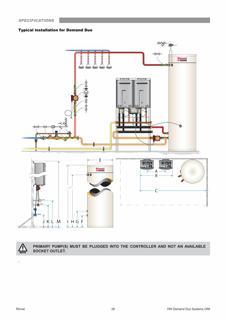
Typical installation for Demand Duo
NOTE
PRIMARY PUMP(S) MUST BE PLUGGED INTO THE CONTROLLER AND NOT AN AVAILABLE SOCKET OUTLET.
.
GHI F
A
C
E
B
KJ L M
SPECIFICATIONS

Rinnai 29 HW Demand Duo Systems OIM
Demand Duo PLUS with multiple gas water heaters – Drawing and Specifications
(All dimensions are in mm)
DD model A B CE
per tank
PTR Inclusions
Primary pump
Total system weight - 250L
tank (Kgs)
Total system weight - 315L
tank (Kgs)
Number of tanks
DD2 28 Ext/Intl
375
750 1600
600
1 x HT575 + 1 x Boiler
Valve
UPS25-80N
120 132 1
DD3 28 Ext/Intl 1125 1975 150 162 1
DD4 28 Ext/Intl 1500 2350 180 192 1
DD5 28 Ext/Intl 1875 2725
UPS32-100N
210 222 1
DD6 28 Ext/Intl 2250 3100 240 252 1
DD7 28 Ext/Intl 2625 3475 270 282 1
DD8 28 Ext/Intl 3000 3850
2 x HT575 + 1 x Boiler
Valve
360 384 2
DD9 28 Ext/Intl 3375 4225 390 414 2
DD10 28 Ext/Intl 3750 4600 450 444 2
DD2 210/250 Ext/Intl
500
1000 1850
600
1 x HT575 + 1 x Boiler
Valve
UPS32-100N
143 155 1
DD3 210/250 Ext/Intl
1500 2350 183 195 1
DD4 210/250 Ext/Intl
2000 2850
2 x UPS32-100N
228 240 1
DD5 210/250 Ext/Intl
2500 3350 268 280 1
DD6 210/250 Ext/Intl
3000 3850 308 320 1
DD7 210/250 Ext/Intl
3500 4350
2 x HT575 + 1 x Boiler
Valve1 x CM10-1
348 360 1
DD8 210/250 Ext/Intl
4000 4850 448 472 2
DD9 210/250 Ext/Intl
4500 5350 488 512 2
DD10 210/250 Ext/Intl
5000 5850 528 552 2
Tank Model F G H I Dry weight Wet weight
250 Litre285 385
1465 1690 60 Kg 310 Kg
315 Litre 1855 2080 72 Kg 385 Kg
HD Model J K L M MJ RatingHD28e
340 440 540 1500
210HD28i 210
HD250e 250HD210e 209
HD210i 209
SPECIFICATIONS

Rinnai 30 HW Demand Duo Systems OIM
Typical installation for Demand Duo Plus
NOTE
PRIMARY PUMP(S) MUST BE PLUGGED INTO THE CONTROLLER AND NOT AN AVAILABLE SOCKET OUTLET.
GHI F
A
C
E
B
KJ L M
SPECIFICATIONS

Rinnai 31 HW Demand Duo Systems OIM
COLD WATER SUPPLY• Connect cold water pipe work to one of the cold inlets of tank, including required valves as shown in diagrams
on previous page to comply to AS/NZS 3500 and local regulations. (Block any unused cold port(s) with brass plug).
• Maximum cold water inlet pressure is 650 kPa. Fit pressure limiting valve (rated @ 700 kPa) if cold water inlet pressure is in excess of 650 kPa.
• Minimum water pressure requirement is 300kPa.
• For ease of draining, it is advisable to fit a "Tee" piece with a capped valve between the cold water isolation valve and the cold water inlet connection on the Demand Duo storage Tank. Tap provided.
Table 1. Pressure Ratings & Other Specifications
Cylinder Rated Pressure (kPa)
PTR Valve Rated Pressure (kPa)
ECV Rated Pressure (kPa)
ECV Fitted
Fit PLV if mains pressure exceeds:
(kPa)
Recommended PLV pressure rating
(kPa)
850 850 700 550 500
A PLV MUST BE fitted if the supply pressure exceeds the limits shown. If the mains pressure is within the limits shown fitment of the PLV is optional.
NOTE
Valves with pressure ratings other than specified are unsuitable and MUST NOT be used.
HOT WATER OUTLET • Connect hot water outlet pipe to 32mm or 50mm fitting on upper left hand side of the storage Tank with union
and isolation valve as required.
• Ensure adequate insulation / lagging is fitted to hot water pipe to minimize heat loss.
Return Pump• A secondary or building return pump may be installed in conjunction with the Rinnai Demand Duo hot water
system. Pump should be sized for minimal temperature loss around the ringmain. Pump must have a check valve on the discharge.
• Return line from building loop is connected to the cold water supply pipe after the check valve. From that point onwards the cold pipe should be insulated.
Gas Supply• Check gas type of Rinnai HD matches gas supply available (LPG or Natural) on job site.
• Gas inlet connection is located at the front bottom of the weather shroud on a DD1 and is the top manifold pipe on a Demand Duo with multiple gas water heater.
• Appropriate gas isolation valve MUST BE fitted to DD1.
• Ensure gas pipe sizing is adequate to deliver the required volume / pressure. Pipe size used on inlet fitting is no indication of pipe size required.
• Refer to appropriate pipe sizing chart in Appendix "F" AS/NZS 5601 for appropriate sized gas pipe that should be used to ensure adequate gas supply.
• Gas meter / LPG cylinder & regulator should also be of a suitable size to ensure sufficient gas supply to the gas installation.
• Purge gas pipe to ensure removal of debris etc prior to final connection.
• Check for gas escapes using suitable methods as listed in Appendix "E" AS/NZS 5601.
Electrical Supply• Each water heater consumes approximately 100 Watts when in operation. It is recommended not to exceed
24 heaters on one electric supply circuit. Refer to the manual supplied with the specific water heater for exact requirements.
INSTALLATION HANDOVER MANUAL

Rinnai 32 HW Demand Duo Systems OIM
FILLING INSTRUCTIONS
Do not turn on pump / water heater before cylinder and water heater are completely full of water.• Flush cold water inlet pipe to remove any debris before final connection to cold water inlet on Rinnai Demand
Duo cylinder.
• Turn on hot water tap to allow air to be expelled while cylinder is filling with cold water.
• Slowly open cold water isolation valve on cold water supply pipe.
• Allow storage tank(s) to fill. Turn off hot water tap once non-aerated water flows through hot water tap.
• Check all connections for water leakage. Tighten as required.
• Purge gas lines until gas is available at water heaters.
• Prime circulating pump(s) before start up by removing chrome screw and allowing water to drip out the end of the pump shaft (as illustrated below).
STARTING INSTRUCTIONS• Turn all Socket Outlets ON.
• The temperature controller will initiate.
• For standard systems "75" should appear in the maintenance monitor window on the gas heater. When flow is created by primary pump. That is the outlet temperature from the water heater. It must be higher then the temperature controller set point.
• The temperature controller will display temperature of water in tank. When it reaches the 65°C set point the pump and therefore, water heater will stop. The display on the water heater will not be lit when not operating.
DEMAND DUO PRINCIPLE OF OPERATION
Cold water enters the storage tank after passing through an isolation and non return valve.
A tee is fitted to the cold inlet pipe down stream from the non return valve. From this tee, one branch connects to the lower inlet of the storage tank and the other branch connects to the primary (tank circulation) pump. (Not applicable to DD1 Models). This pumps water to the inlet of the heat source. The water heaters will only operate when this pump is running.
The heated water from the HD (s) returns to the tank(s) at the second lowest connection point, located above the cold inlet.
Hot water leaves the tank from the top of the tank. This may be circulated around the building and returned, via a ringmain pump (set) to the cold inlet before the tee as described above.
When there is a hot water draw off, cold water enters the tank and pushes the hot water out of the tank towards the outlet, as per any storage hot water system.
When the temperature in the tank drops below the temperature set point, the temperature controller activates the primary pump(s). They draw water from the cold water feed to the tank, the tank itself, or a combination of both. As stated previously, this water is then heated by the HD (s) and returns to the tank heated. This process is continued until the temperature set point is reached and the pump is switched off.
The outlet temperature controller setting of the HD (s) must be set at least three (3) degrees hotter then the controller set point. Factory settings are: HD (s) 75°C, Thermostat 65°C.
INSTALLATION HANDOVER MANUAL

Rinnai 33 HW Demand Duo Systems OIM
THERMOSTATIC CONTROLLER OPERATION
The thermostatic controller is factory preset and designed to control the operation of primary pumps between storage tank and external heat source, such as HD28, HD250 and HD210.
It has many functions and temperature sets points available which are described in the manual provided with the controller.
DEMAND DUO PREVENTATIVE MAINTENANCE
All Items• Inspect for damage, corrosion or water leaks.
Tank• Ensure that tank is not leaking.
• Ensure that PTR valves are not leaking. It is normal for PTR valve to operate during the heating cycle, relieving pressure as the water is expanding. The PTR Valve is rated to 850 kPa and cold inlet pressure should not exceed 500-700 kPa. If it does, then a pressure reduction valve should be fitted to the cold water inlet.
• Valve may be operating if water temperature in tank is close to 99°C. If this is the case thermostatic controller or other heating equipment has failed to operate correctly. Contact Rinnai service department.
• If pressure and temperature are low but valve is leaking, pull the lever for up to 30 seconds, as some foreign material may be jammed in the valve seat. If valve fails to seat correctly, valve should be replaced. PTR Valves are a non-repairable safety device and should be replaced with the correct model and pressure rating.
Primary Pump• Primary pumps are plugged into the relevant position on the thermostatic controller. Refer to manual provided
with the controller.
• Some projects may have larger and/or dual pumps for redundancy or long primary pipe run situations.
• Pump(s) operate only when activated by the thermostatic controller and the pump operation is indicated on the controller screen.
• Ensure that pumps are installed in a weather proof location or protected from being subjected to water ingress. Wet pump electrics may cause failure. Water can run along power lead so keep the lead looping under the pump and curving upwards toward the electrical box.
• Ensure shaft is horizontal. DO NOT aim shaft upwards or downwards.
• DO NOT locate terminal box under pump housing. Position it on top preferable or on side
• Bleed pump with chrome screw at end of pump casing. This will be facing towards you when the pump shaft is horizontal. Pump runs on water bearing and is critical for life of pump. Excessive noise indicates damage or lack of bleed.
• When this screw is removed the spinning / stationary impeller shaft can be inspected.
• Ensure pump direction of flow arrow is towards the heat source.
• If shaft is spinning but there is no flow: Check ball valves and any non return valve for correct installation and operation. UPS25-80N and UPS32-100N pumps have inbuilt ball valves in the unions. Line up screwdriver slot parallel to pipe to position them open.
26 27
Min. / Max.-25 °C / +95 °C
UP(S) KUP(S) KU
INSTALLATION HANDOVER MANUAL

Rinnai 34 HW Demand Duo Systems OIM
HEAVY DUTY (HD) HEAT SOURCE• Ensure that filter at water inlet is clean. NOTE: that this is an ‘O’ ring seal and does not need to be
excessively tightened. Just make sure ‘O’ ring is engaged inside machined surface in brass housing. Isolate water supply to DD before removing filter for cleaning and inspection. Ensure water in storage cylinder is not excessively hot before removing HD inlet filter.
• Ensure all HD (s) are operating. Ensure power is available to HD (s) if it is not operating. Check Socket Outlet. Ensure power is available to the HD (s) before applying power to thermostatic controller and pump(s).
• Many new jobs or ones where the gas supply has been modified need to purge the gas supply lines as they are full of air. Purge should be carried in accordance with AS/NZS 5601, Appendix 'D'.
• Look at flame through inspection window for conical shape, blue base and yellow tip. Flame height will vary if heater is modulating. Inspection window is located behind the front cover on the burner unit (next to flame rod) of the appliance.
• All HD models: when operating the number displayed should be higher than the temperature setting on the thermostatic controller.
• Eg Tank = 65°C,HD = 75°C. These are factory standard settings.
• Eg Tank = 82°C, HD = 85°C. These are the maximum allowable settings.
• All HD models will display a fault number if one has occurred. The following table lists all of the fault codes.
• In jobs that operate for long hours and/or in dusty or smoky environments the combustion air fan may become dirty. This may be indicated by fault 10. Contact Rinnai Service.
• Internal heaters may operate for a short period of time and then stop. This can be caused by the flueing not being pushed together properly and exhaust gases are re-entering the inlet air. Push the flue together to remedy this. Also inspect flue terminal for any cause to divert exhaust air back into the inlet air. Ensure flue is terminated correctly in accordance with AS/NZS 5601.
FLUE LENGTH DIPSWITCHES - REU-VCM
IMPORTANT
Short flue: Installations where the total flue does NOT exceed 7 metres (refer to table below), the SW1 of both DipSW1 & dipSW2 are set to 'ON'.
Extended flue: Installation where the total flue length exceeds 7 metres (refer to table below), the SW1 of both DipSW1 & DipSW2 are set to 'OFF'.
For Internal (FFU) models only (except HD210i)
Have you used only RINNAI FFU flueing components?
If flue exceeds 7m, dip-switch 1 of SW1 is to be switched to the ‘OFF’ postition as shown.
SW1
1OFFDipswitches
DipSW2
DipSW1
DipSW1
OFF ON 12
34
56
78
OFF ON 12
34
56
78
Short Flue Extended Flue
DipSW1
DipSW2
OFF ON 12
34
56
78
OFF ON 12
34
56
78
OFF ON 12
34
56
78
FF
FF
OFF ON 12
34
56
78
FF
FF
Short Flue Extended Flue
Short Flue Extended Flue
DipSW1
DipSW2
REU-VR/VRM
REU-VCM
INSTALLATION HANDOVER MANUAL

Rinnai 35 HW Demand Duo Systems OIM
The Rinnai Continuous Flow water heaters have self diagnostic capability. If a fault occurs, an Error Code will flash on the status monitor or inbuilt controller. If you have Temperature Controllers, this assists with diagnosing the fault, and may enable you to overcome a problem without a service call. Please quote the code displayed when enquiring about service.
HD Fault Codes
Cod
e
Description Remedy
- Noticeable reduction in water flow Inlet water filter needs to be cleaned - Service call
03 Power interruption during Bath fill (Water will not flow on power reinstatement) Turn off all hot water taps Press On/Off twice
05 By-Pass Flow Control Failure Service Call
10 Air Supply or Exhaust Blockage or Condensate Pipe Blockage Service Call
11 No ignition / No gas supply Check gas is turned on at water heater and gas meter or cylinder
12 Flame Failure / Low gas flowCheck gas is turned on at water heater and gas
meter or cylinder. Check there are no obstructions to the flue outlet
14 Heat Exchanger Overheat Failure Service Call
15 Venturi Control Failure Service Call
16 Over Temperature Warning Service Call
17 Venturi Blockage Service Call
19 Electrical Earthing Failure Service Call
21 Data Transfer Error Service Call
32 Outgoing Water Temperature Sensor Failure Service Call
33 Heat Exchanger Thermistor Failure Service Call
34 Combustion Air Temperature Sensor Failure Service Call
38 Exhaust Thermistor Failure Service Call
41 Freeze Protection Thermistor Failure Service Call
51 Inlet Thermistor Failure Service Call
52 Gas Valve Failure Service Call
54 High Exhaust Gas Temperature Failure Service Call
S5 Scheduled Service Reminder Service Call
Se Cascade Connection Failure Service Call
61 Combustion Fan Failure Service Call
65 Water Flow Control Failure (Does not stop flow properly) Service Call
70 PCB Failure Service Call
71 Solenoid Valve Circuit Failure Service Call
72 Flame Rod Failure Service CallWireless water controller (when fitted) is ‘Out of Range’ due to the distance from transceiver or
an obstruction.
Move wireless water controller or transceiver or remove the obstruction.
NOTE
Some fault codes are model specific and so not all codes will display on all models. If the fault code being displayed is not listed above, contact Rinnai for advice.
In the majority of cases, you may be able to clear the Error Code simply by turning the hot water tap OFF, then ON again. If this does not clear the Error Code, try pushing the On/Off button OFF, then ON again. If the Error Code still remains, contact Rinnai for advice.
FAULT FINDING

Rinnai 36 HW Demand Duo Systems OIM
RINGMAIN PUMP
• These are used for circulating water around the building. They are normally left on or may have a time clock to switch it off at night when the building is not in use.
• These pumps do not pressurise the system.
• They must have a non return valve.
• Swing non return valves must be horizontal or upward as the rely on gravity to close the valve.
• Spring check valves can be located on any plane but may contribute excessive back pressure and restrict the pump flow rate.
• Return water should only be slightly cooler than water leaving the tank. If the temperature drop around the circuit is too high it may indicate that the ring main pump flow rate is not high enough and indicates a design fault or a blockage in the pipework (or poor pipework insulation). Investigate valves and operation of pump (same procedure as primary pump).
SERVICE
Rinnai recommend that all commercial water heater installations have a service arrangement.
Annual services are recommended at a minimum. Refer to the back cover for contact information.
FAULT FINDING

Rinnai 37 HW Demand Duo Systems OIM
DETAILS
Company
Phone No,
Date
Project
COMMERCIAL HOT WATER SYSTEM COMMISSIONING CHECK-LIST
System DetailsProduct CodeInstallation Type External / InternalNumber of Water HeatersWater Heater ModelGas Type Natural / LPGNumber of Storage TanksStorage Tan/s ModelNumber of Primary Pump/s & Control System/sPump/s ModelNumber of Return Pump/sPump/s ModelInstallationOverall Installation – Satisfactory? Yes / NoCold Water Strainer, Check Valve, PLV IsolationValve/s Installed?
Yes / No
Return Strainer Installed? Yes / No / NAStorage Tanks’ hydraulically balanced? Yes / No / NAVentilation Requirements – Satisfactory? Yes / NoIndividual Co-Axil Flue Installation – Satisfactory? Yes / No / NADip Switch Setting Short / LongCommon Flue Installation – Satisfactory? Yes / No / NAPrimary Pump/s Vented? Yes / No / NAReturn Pump/s Vented? Yes / No / NAAir removed from flow and return hydraulic circuit? Yes / NoAll drains to tundish completed? Yes / NoSocket Outlet Installation – Satisfactory? Yes / No / NAMECS/Cascade Staging System wiring completed? YES / No / NAParametersGas Pressure (@1.13-2.75kPa–NG) / @2.75kPa-LPG)
• Static
• RunningInlet Water Pressure (kPa)Permanent Power Supply (V/Phase/Hz/A) 240/1/50
COMMISSIONING

Rinnai 38 HW Demand Duo Systems OIM
General System OperationAll Valves in Open Position Yes / NoController Set Temperature (°C)Water Heater Set Temperature(°C)Return Pumps Controller Set ModeWater Heater/s Operation – Satisfactory? Yes / NoTanks’ PTR Valves’ Operation – Satisfactory? Yes / NoStaging System Operation – Satisfactory? Yes / No / NAPrimary Pump/s Operation – Satisfactory? Yes / No / NAReturn Pump/s Operation – Satisfactory? Yes / No / NAStorage Tank Reached Temperature? Yes / No / NAReturn Water Temperature?Overall System Operation – Satisfactory? Yes / NoComments
Client to carry out regular preventative maintenance as below:
• Inlet Strainer/s; Hot Water Return Strainer & Water Heaters Inlet Strainers: Once every week for the first month & three monthly from there onwards
• For other details refer to Operation & Maintenance Manual
• For effective operation of the system; service the package once every six (6) months as per the manufacturer’s instructions.
• In compliance to AS/NZS 5601.1 figure 6.2 minimum clearance required for any air intake from the exhaust of a water heater is 1500mm.
• In compliance to AS/NZS 3500.2 section 6.8.4 termination clause (e), vents shall terminate in the open air and in a location not less than 5.0m in any direction from any air duct intake.
• Warranty:https://www.rinnai.com.au/wp-content/uploads/2018/02/15401043-V6-Commercial-Warranty-Booklet.pdf
• Installation of system to comply within Rinnai installation guidelines and relevant codes
• Drainage: Provide appropriately designed drainage system in compliance to applicable building codes and regulations to prevent property and equipment damage.
Customer Representative Date
COMMISSIONING

Rinnai 39 HW Demand Duo Systems OIM
NOTES

PN15401029 40 07-001 HW Demand Duo Systems OIM Issue 14 - October 2021
Rinnai Australia Pty LtdABN 74 005 138 769 | AU45204
100 Atlantic Drive, Keysborough, Victoria 3173P.O. Box 460, Braeside, Victoria 3195Tel: (03) 9271 6625Fax: (03) 9271 6622
National Help LineTel: 1300 555 545* Fax: 1300 555 655Monday to Friday, 8.00 am to 5.00 pm EST.
After Hours Hot Water Service LineTel: 1800 000 340*
*Cost of a local call higher from mobile or public phones.
For further information visit www.rinnai.com.auor email [email protected]
Rinnai has a Service and Spare Parts network with personnel who are fully trained and equipped to give the best service on your Rinnai appliance. If your appliance requires service, please call our National Help Line. Rinnai recommends that this appliance be serviced every year.
With our policy of continuous improvement, we reserve the right to change, or discontinue at any time, specifications or designs without notice.