department of architecture abubakar tafawa balewa ... notes/arc … · parts of a truss the joints...
TRANSCRIPT

1
DEPARTMENT OF ARCHITECTURE
ABUBAKAR TAFAWA BALEWA UNIVERSITY, BAUCHI
ARC 615: ADVANCED BUILDING STRUCTURES
LESSON 4: VECTOR ACTIVE STRUCTURAL SYSTEMS
4.1 Introduction
4.2 Structural concept of planar trusses
4.3 Planar truss structures
4.3.1 Examples of planar truss structures
4.4 Curved truss structures
4.4.1 Examples of curved-truss structures
4.5 Prismatic (3D) trusses
4.5.1 Examples of prismatic (3D) truss structures
4.6 Space trusses
4.6.1 Structural concept of space trusses
4.6.2 Examples of space-truss structures
4.7 References
4.1 Introduction
A truss is a structure composed of slender members joined together at their end points. A
truss requires less material than a solid beam in attaining long spans for carrying heavy
loads, making it especially useful in constructing bridges and roofs.
The connected pieces forming the top of a truss are called the upper chord, and those
forming the bottom of a truss are called the lower chord. Individual sloping and vertical
pieces connecting the chords are called web members, and the whole assembly of these
pieces is called the web. At panel points, where the individual pieces intersect, the pieces
are connected by bolts, rivets, or welds.
.

2
Parts of a truss
The joints connections are usually formed by bolting or welding the ends of the members to a common
plate, called a gusset plate, or by simply passing a large bolt through each member.
Parts of a truss. Note the gusset plates.
The framing carried by a truss generally is designed so that loads bear on the truss at the
intersections of a chord and web member. As a result, the chord and web members are
subjected only to tension or compression, and thus less material can be used than what is
needed when the truss members also have to resist bending.
This lesson covers four types of truss structures:
Planar trusses: all elements in a single plane. The upper and lower chords may not
be parallel.
Curved trusses: planar trusses with the upper or lower chord, or both chords,
forming an arc.
Prismatic (3D) trusses:
Space trusses

3
4.2 Structural concept of trusses
A Truss is composed of slender two-force members joined together at their end points.
Joints are modelled by smooth pin connections. Members are either under tension or
compression.
Truss members work either in tension or compression. They should ideally not experience bending moments.
Joints
The ideal connection of a truss joint is by pinned connection. This will allow the member to
rotate, but not translate (move) in any direction. The loads carried by a truss are only
concentrated forces

4
Joint of a truss made by pinning.
Joint of a truss made by pinning.

5
Joint of a truss made by pinning.
Joints are however commonly made by bolting, riveting or welding to gusset plates.
However, even when members are welded, riveted or bolted at joints, it is assumed that
the joints act as if they are pinned because the members are designed to support only axial
loads.
Bolting of truss members to a gusset plate
Joint-Welded
(Gusset Plate)
Member
(Wooden Strut)
Joint-Welded
(Gusset Plate)
Member
(Wooden Strut)

6
Joint of a truss made by riveting.
Joint of a truss made by welding.
Supports
The 2 common types of support used for trusses are pinned and roller supports.
Roller supports
Roller supports are free to rotate and translate along the surface upon which the roller
rests. The surface can be horizontal, vertical, or sloped at any angle. The resulting reaction
force is always a single force that is perpendicular to, and away from, the surface. Roller

7
supports can also take the form of rubber bearings, rockers, or a set of gears which are
designed to allow a limited amount of lateral movement.
Pinned supports
A pinned support can resist both vertical and horizontal forces but not a moment. They will
allow the structural member to rotate, but not to translate in any direction. Many
connections are assumed to be pinned connections even though they might resist a small
amount of moment in reality. It is also true that a pinned connection could allow rotation in
only one direction; providing resistance to rotation in any other direction. The knee can be
idealized as a connection which allows rotation in only one direction and provides
resistance to lateral movement. A single pinned connection is usually not sufficient to make
a structure stable. Another support must be provided at some point to prevent rotation of
the structure. The representation of a pinned support includes both horizontal and vertical
forces.
Roller support of a truss.

8
Roller support of a truss.
Rocker support of a truss.
9
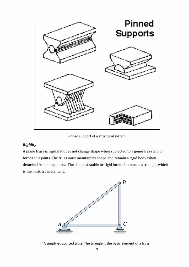
Pinned support of a structural system.
Rigidity
A plane truss is rigid if it does not change shape when subjected to a general system of
forces at it joints. The truss must maintain its shape and remain a rigid body when
detached from it supports. The simplest stable or rigid form of a truss is a triangle, which
is the basic truss element.
A simply-supported truss. The triangle is the basic element of a truss.

10
Zero force members
These are structural members that carry no force. They are used to provide stability during construction
and if intermittent loading of the truss changes. They can also shorten chord length and increase
buckling capacity of compression members.
Example of zero force members. Web AF and chord AB do not carry any force.
4.3 Planar truss structures
When all members of a truss lie in a single plane, that truss is planar. The loads carried by the truss lie in
the same plane.
Parts of a planar truss

11
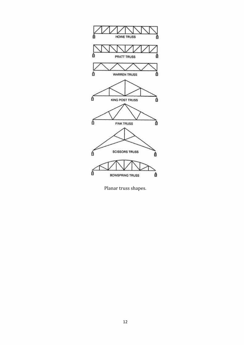
Planar truss shapes
12
Planar truss shapes.

13
4.3.1 Examples of planar truss structures
Example of a planar truss.
Example of a planar truss.

14
4.4 Curved truss structures
Curved steel structures are planar trusses with either the upper chord or the lower chord, or both
chords forming an arc.
4.4.1 Examples of curved-truss structures
Curved steel truss
Double-curved steel truss
Curved truss (bowstring truss)
15
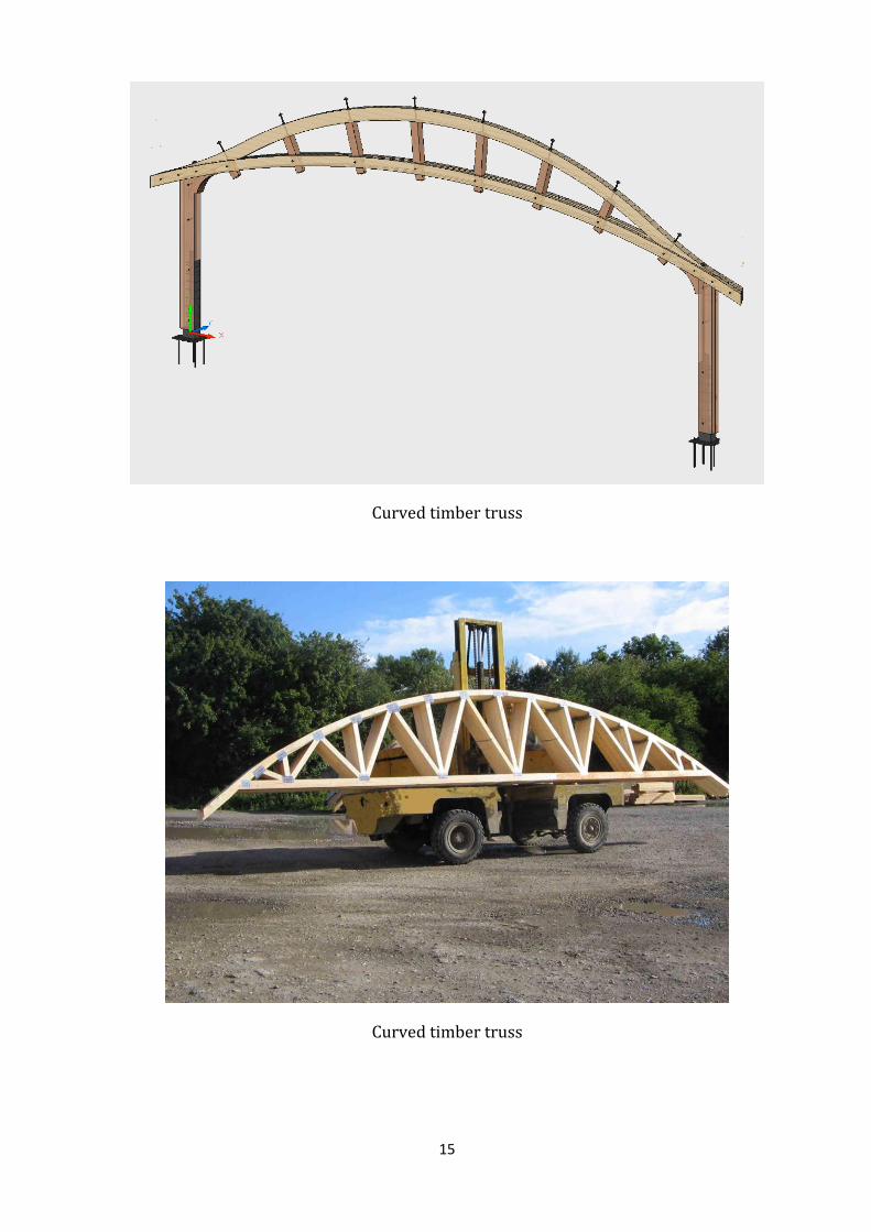
Curved timber truss
Curved timber truss

16
4.5 Prismatic (3D) trusses
A prismatic 3D truss is a truss composed of prisms. It is a 3D truss with a single upper chord and two
lower chords, or vice versa. The connections of the webs with the chords form prisms. The truss can be
straight or curved.
4.5.1 Examples of prismatic (3D) truss structures
3D prismatic truss
Curved 3D prismatic trusses

17
Curved 3D prismatic trusses, Hamburg airport departure hall
Curved 3D prismatic trusses, Hamburg airport departure hall

18
Curved 3D prismatic trusses, Hamburg airport departure hall
Example of a prismatic truss. Skating rink, Munich.
4.6 Space trusses
Space frame structures are structural systems with three dimensional assemblies of linear
elements, in which the forces are transferred in a three dimensional manner. Skeleton,
three dimensional frame works consisting of pin connected bars are called space trusses.
They are characterised by hinged joints with no moments or torsional resistance. All
members carry only axial compression or tension.

19
The terms space frame and space truss are often used interchangeably. Space trusses are
however only a type of space frame structure
A space grid may be defined as two or more sets of parallel beams intersecting each other
at any angle and loaded by an external loading normal to the plane. They are characterised
as two-way or three-way depending upon whether the members intersecting at a node run
in two or three directions. Space grids are essentially planar, but several layers can be
combined to form multi-layer grid trusses.
A space truss can be formed by two or three layers of grids. A double layer grid consist of
two plane grids forming the top and bottom layers, parallel to each other and
interconnected by vertical and diagonal members. A space truss is a combination of
prefabricated tetrahedral, octahedral or skeleton pyramids or inverted pyramids having
triangular, square or hexagonal basis with top and bottom members normally not lying in
the same vertical plane.
Space truss (two-way truss system)

20
Advantages of space trusses
1. They are light, structurally efficient and use materials optimally. They can be
designed in such a way that the total weight is between 15 to 20kg/m2
2. They can be built up from simple, prefabricated units of standard size and shape.
Hence they can be mass-produced in the factory, and can be easily and rapidly
assembled at site using semi-skilled labour.
3. The small size components simplify the handling, transportation and erection.
4. They are an elegant and economical means of covering large column-free spaces.
5. They allow great flexibility in designing layout and positioning of end supports.
6. Services such as lighting, air conditioning can be integrated within space structures.
7. The use of complicated and expensive temporary supports during erection is
eliminated.
8. They possess great rigidity and stiffness for a given span/depth ratio and hence are
able to resist large concentrated and unsymmetrical loading. Local overloading can
be taken care of by built-in reserve strength. They do not collapse locally. They are
highly redundant structures.
4.6.1 Structural concept of space trusses
Components of space trusses
1. Axial members which are preferably tubes.
2. Connectors which join the members together. The Mero connector is popularly
used.
3. Bolts connecting members with nodes.
Depending upon the connecting system space truss systems are classified as Nodular and
Modular systems.
Nodular systems consist of linear truss members interconnected through the nodes.
Modular systems consist of prefabricated modular units instead of individual members
and nodes. These modules of various types, sizes and shapes are assembled together by
means of high strength friction bolts. The space deck system and the unibat system are the
two well-known examples of modular systems.

21
A Mero connector.
4.6.2 Examples of space-truss structures
Single layer space truss

22
Double layer space truss
4.7 References
Massachusetts Institute of Technology (2016). Architectonics – the Science of Architecture.
Support and Connection Types. Retrieved from
http://web.mit.edu/4.441/1_lectures/1_lecture13/1_lecture13.html.