department of electronics and communications digital...
TRANSCRIPT

©2000, John Wiley & Sons, Inc.Haykin/Communication Systems, 4th Ed
EC 744 Wireless Communications Spring 2007
Mohamed Essam KhedrDepartment of Electronics and Communications
Digital Modulation Techniques
WWW.aast.edu/~khedr/Courses

©2000, John Wiley & Sons, Inc.Haykin/Communication Systems, 4th Ed
Syllabus
• TentativelyEqualization techniquesWeek 6
Mid Term examWeek 7
802.11 and Mac evaluationWeek 8
Energy models in 802.11Week 9
Wimax and Mac layerWeek 10
PresentationsWeek 11
PresentationsWeek 12
PresentationsWeek 13
Final ExamWeek 15
PresentationsWeek 14
Diversity techniquesWeek 5
Modulation techniques, single and multi-carrierWeek 4
Cellular concept and system design fundamentalsWeek 3
Wireless channels, Statistical Channel modelling, Path loss models
Week 2
Overview, Probabilities, Random variables, Random process
Week 1
©2000, John Wiley & Sons, Inc.Haykin/Communication Systems, 4th Ed
Chapter 6
Passband Data Transmission

©2000, John Wiley & Sons, Inc.Haykin/Communication Systems, 4th Ed
Figure 6.1Illustrative waveforms for the three basic forms of signaling binary information. (a) Amplitude-shift keying. (b) Phase-shift keying. (c) Frequency-shift keying with continuous phase.

©2000, John Wiley & Sons, Inc.Haykin/Communication Systems, 4th Ed
Figure 6.2Functional model of passband data transmission system.

©2000, John Wiley & Sons, Inc.Haykin/Communication Systems, 4th Ed
Figure 6.3Signal-space diagram for coherent binary PSK system. The waveforms depicting the transmitted signals s1(t) and s2(t), displayed in the inserts, assume nc = 2.

©2000, John Wiley & Sons, Inc.Haykin/Communication Systems, 4th Ed
Figure 6.4Block diagrams for (a) binary PSK transmitter and (b) coherent binary PSK receiver.

©2000, John Wiley & Sons, Inc.Haykin/Communication Systems, 4th Ed
Figure 6.5Power spectra of binary PSK and FSK signals.

©2000, John Wiley & Sons, Inc.Haykin/Communication Systems, 4th Ed
Figure 6.6Signal-space diagram of coherent QPSK system.

©2000, John Wiley & Sons, Inc.Haykin/Communication Systems, 4th Ed
Figure 6.7(a) Input binary sequence. (b) Odd-numbered bits of input sequence and associated binary PSK wave. (c) Even-numbered bits of input sequence and associated binary PSK
wave. (d) QPSK waveform defined as s(t) = si1φ1(t) + si2φ2(t).

©2000, John Wiley & Sons, Inc.Haykin/Communication Systems, 4th Ed
Figure 6.8Block diagrams of (a) QPSK transmitter and (b) coherent QPSK receiver.

©2000, John Wiley & Sons, Inc.Haykin/Communication Systems, 4th Ed
Figure 6.9Power spectra of QPSK and MSK signals.

©2000, John Wiley & Sons, Inc.Haykin/Communication Systems, 4th Ed
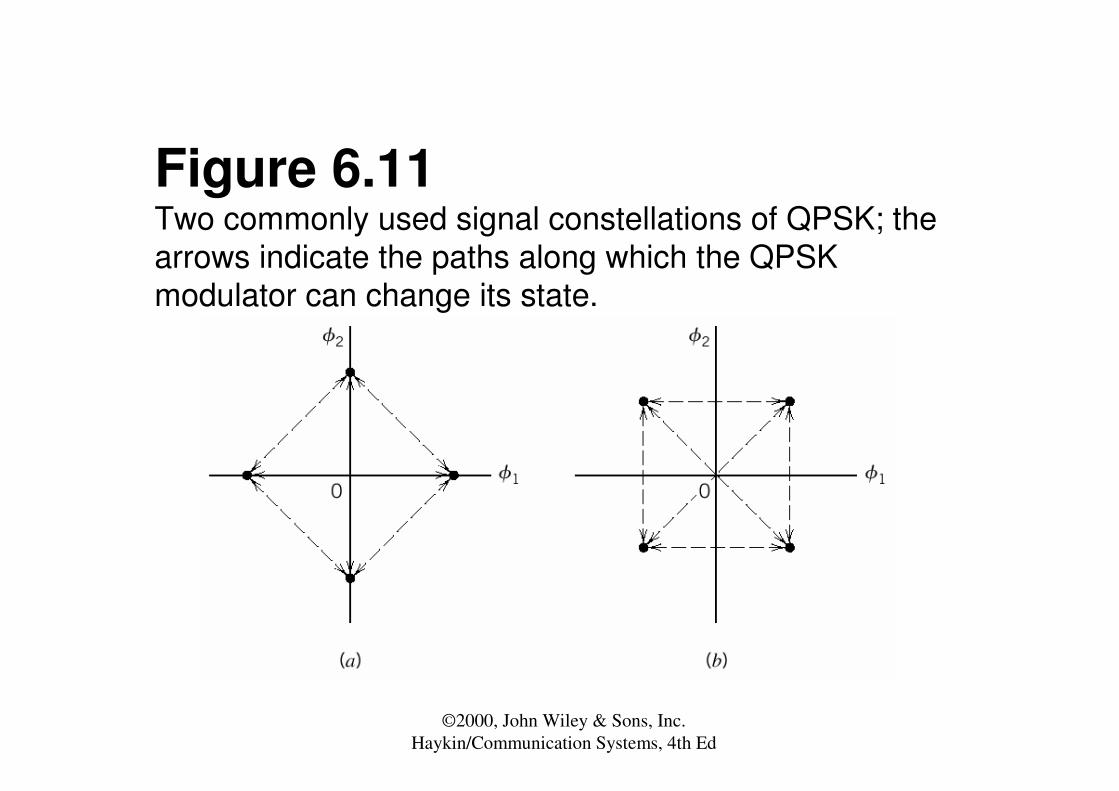
The two QPSK constellations. Note that they differ by � /4. When going from (1,1) to (-1, -1), the phase is shifted by �. When going from (1, -1) to (1,1), the phase shifts by � /2. Thus, depending on the incoming symbol, transitions from (1,1) can occur to (1,1), (1,-1), (-1, 1), or (-1, -1) or vice versa, leading to phase shifts of 0, ± � /2, or ± � in QPSK. I and Q represent the in-phase and quadrature bits, respectively. Arrows show all possible transitions.
©2000, John Wiley & Sons, Inc.Haykin/Communication Systems, 4th Ed
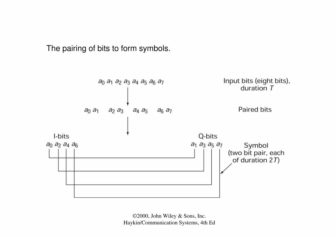
The pairing of bits to form symbols.

©2000, John Wiley & Sons, Inc.Haykin/Communication Systems, 4th Ed
Figure 3.36. Explanation of the phase shifts observed in QPSK, indicating the phases of the symbols and the phase difference between symbols.

©2000, John Wiley & Sons, Inc.Haykin/Communication Systems, 4th Ed
Figure 3.37. (a) QPSK transmitter. (b) QPSK receiver.

©2000, John Wiley & Sons, Inc.Haykin/Communication Systems, 4th Ed
Figure 6.10Possible paths for switching between the message points in (a) QPSK and (b) offset QPSK.
©2000, John Wiley & Sons, Inc.Haykin/Communication Systems, 4th Ed
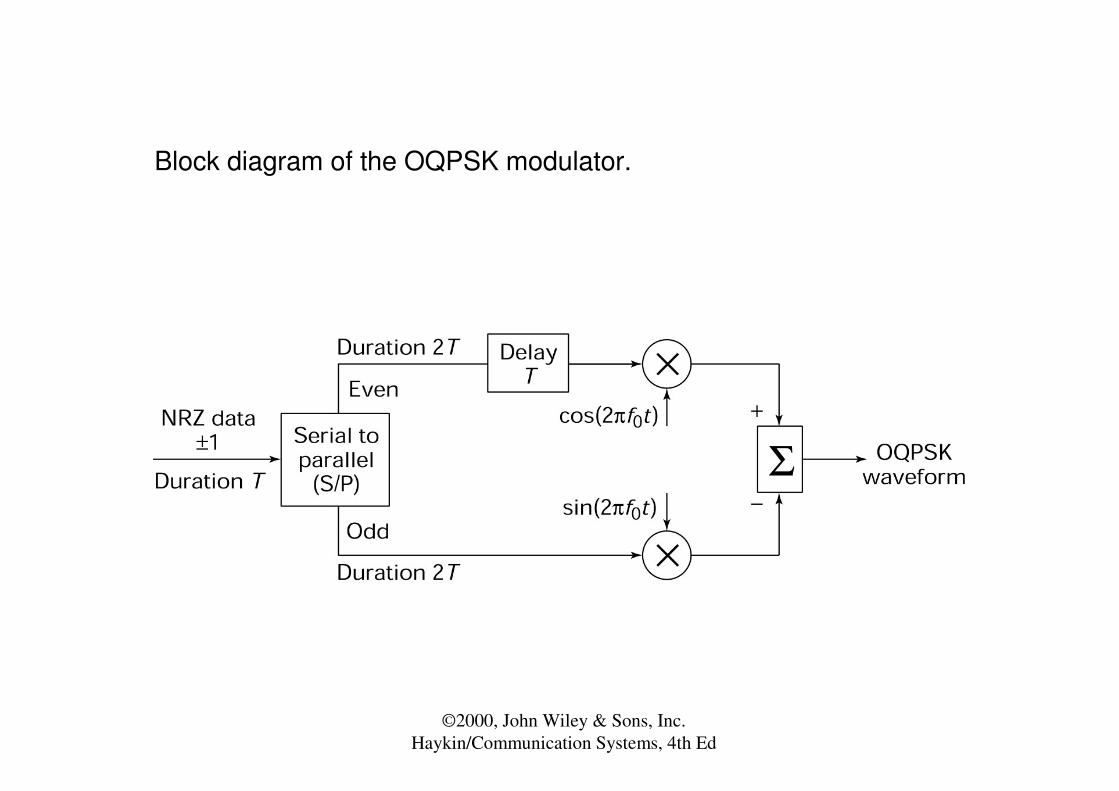
Block diagram of the OQPSK modulator.

©2000, John Wiley & Sons, Inc.Haykin/Communication Systems, 4th Ed
Explanation of the phase transitions in OQPSK.
©2000, John Wiley & Sons, Inc.Haykin/Communication Systems, 4th Ed
Figure 6.11Two commonly used signal constellations of QPSK; the arrows indicate the paths along which the QPSK modulator can change its state.

©2000, John Wiley & Sons, Inc.Haykin/Communication Systems, 4th Ed
Figure 6.12Eight possible phase states for the π/4-shifted QPSK modulator.

©2000, John Wiley & Sons, Inc.Haykin/Communication Systems, 4th Ed
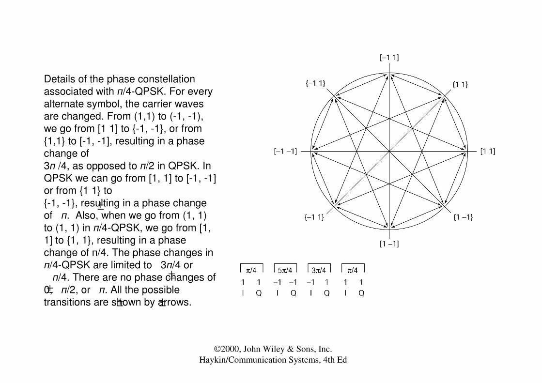
Phase encoding for � /4-QPSK. The brackets [ ] and { } correspond to the two respective constellations.
©2000, John Wiley & Sons, Inc.Haykin/Communication Systems, 4th Ed
Details of the phase constellation associated with �/4-QPSK. For every alternate symbol, the carrier waves are changed. From (1,1) to (-1, -1), we go from [1 1] to {-1, -1}, or from {1,1} to [-1, -1], resulting in a phase change of 3� /4, as opposed to �/2 in QPSK. In QPSK we can go from [1, 1] to [-1, -1] or from {1 1} to {-1, -1}, resulting in a phase change of �. Also, when we go from (1, 1) to (1, 1) in �/4-QPSK, we go from [1, 1] to {1, 1}, resulting in a phase change of �/4. The phase changes in �/4-QPSK are limited to 3�/4 or�/4. There are no phase changes of
0, �/2, or �. All the possible transitions are shown by arrows.
±
±±
± ±

©2000, John Wiley & Sons, Inc.Haykin/Communication Systems, 4th Ed
Block diagram of the � /4-DQPSK transmitter.
-pi/410
-3pi/411
3pi/401
Pi/400
Phase changeInput dibit
∆+= −1kk ϑϑ

©2000, John Wiley & Sons, Inc.Haykin/Communication Systems, 4th Ed
Figure 6.13Block diagram of the π/4-shifted DQPSK detector.

©2000, John Wiley & Sons, Inc.Haykin/Communication Systems, 4th Ed
Figure 6.14Illustrating the possibility of phase angles wrapping around the positive real axis.

©2000, John Wiley & Sons, Inc.Haykin/Communication Systems, 4th Ed
Figure 6.15(a) Signal-space diagram for octaphase-shift keying (i.e., M = 8). The decision boundaries are shown as dashed lines. (b) Signal-space diagram illustrating the application of the union bound for octaphase-shift keying.
©2000, John Wiley & Sons, Inc.Haykin/Communication Systems, 4th Ed
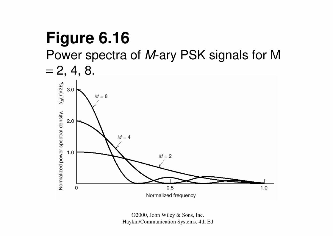
Figure 6.16Power spectra of M-ary PSK signals for M = 2, 4, 8.

©2000, John Wiley & Sons, Inc.Haykin/Communication Systems, 4th Ed
Figure 6.17(a) Signal-space diagram of M-ary QAM for M = 16; the message points in each quadrant are identified with Gray-encoded quadbits. (b) Signal-space diagram of the corresponding 4-PAM signal.

©2000, John Wiley & Sons, Inc.Haykin/Communication Systems, 4th Ed
Figure 6.25Signal-space diagram for binary FSK system. The diagram also includes two inserts showing example waveforms of the two modulated signals s1(t) and s2(t).

©2000, John Wiley & Sons, Inc.Haykin/Communication Systems, 4th Ed
Figure 6.26Block diagrams for (a) binary FSK transmitter and (b) coherent binary FSK receiver.

©2000, John Wiley & Sons, Inc.Haykin/Communication Systems, 4th Ed
Figure 6.27Phase tree of CFM.
©2000, John Wiley & Sons, Inc.Haykin/Communication Systems, 4th Ed
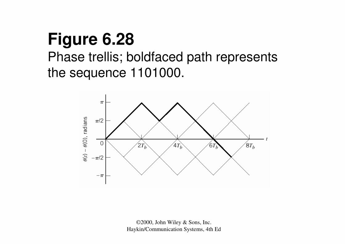
Figure 6.28Phase trellis; boldfaced path represents the sequence 1101000.

©2000, John Wiley & Sons, Inc.Haykin/Communication Systems, 4th Ed
Figure 6.29Signal-space diagram for MSK system.

©2000, John Wiley & Sons, Inc.Haykin/Communication Systems, 4th Ed
Figure 6.31Block diagrams for (a) MSK transmitter and (b) coherent MSK receiver.

©2000, John Wiley & Sons, Inc.Haykin/Communication Systems, 4th Ed
Figure 6.36Power spectra of M-ary FSK signals for M = 2, 4, 8.
©2000, John Wiley & Sons, Inc.Haykin/Communication Systems, 4th Ed
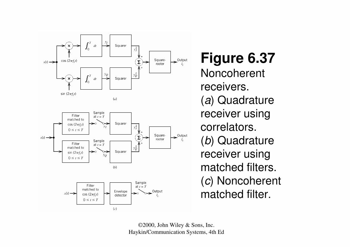
Figure 6.37Noncoherentreceivers. (a) Quadraturereceiver using correlators. (b) Quadraturereceiver using matched filters. (c) Noncoherentmatched filter.

©2000, John Wiley & Sons, Inc.Haykin/Communication Systems, 4th Ed
Figure 6.38Output of matched filter for a rectangular RF wave: (a) θ = 0, and (b) θ = 180 degrees.

©2000, John Wiley & Sons, Inc.Haykin/Communication Systems, 4th Ed
Figure 6.39(a) Generalized binary receiver for noncoherentorthogonal modulation. (b) Quadraturereceiver equivalent to either one of the two matched filters in part (a); the index i = 1, 2.

©2000, John Wiley & Sons, Inc.Haykin/Communication Systems, 4th Ed
Figure 6.42Noncoherent receiver for the detection of binary FSK signals.

©2000, John Wiley & Sons, Inc.Haykin/Communication Systems, 4th Ed
Figure 6.43Block diagrams of (a) DPSK transmitter and (b) DPSK receiver.

©2000, John Wiley & Sons, Inc.Haykin/Communication Systems, 4th Ed
Figure 6.44Signal-space diagram of received DPSK signal.

©2000, John Wiley & Sons, Inc.Haykin/Communication Systems, 4th Ed
• ML slides
©2000, John Wiley & Sons, Inc.Haykin/Communication Systems, 4th Ed
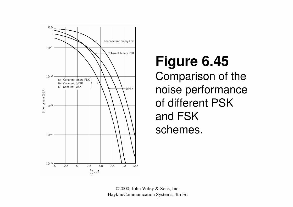
Figure 6.45Comparison of the noise performance of different PSK and FSK schemes.
©2000, John Wiley & Sons, Inc.Haykin/Communication Systems, 4th Ed