department of information engineering1 ele1110c basic circuit theory dr. michael chang –mchang @...
Post on 20-Dec-2015
214 views
TRANSCRIPT

1Department of Information Engineering
ELE1110C Basic Circuit Theory
• Dr. Michael Chang
– mchang @ ie.cuhk.edu.hk
– Room 811
• Marking scheme: 30% mid-term, 70% final exam
• Newsgroup
– cuhk.ie.1110C
• IEG1810 Lab instructions
– record all your results in a A4-size log book
– Hand in your log book to the tutors immediately after each lab session

2Department of Information Engineering
Textbooks for IEG1810 (lab) and ELE1110C/D
• Text
– Student Manual for the Art of Electronics by Hayes and Horowitz (1st ed., Cambridge University Press)
• Use by this course and the lab (IEG1810)
• Only use the first 12 chapters
• Reference
– The Art of Electronics by Horowitz and Hill (2nd ed., Cambridge University Press)
• more detailed explanation

3Department of Information Engineering
Lab safety briefing and registration
• Lab period :
– Starting after the 3rd week
– Every Mon/Tues/Wed/Thurs
• This Monday/Tuesday/Wednesday/Thursday
– 3:30-4:15pm in room 1009 (ERB)
– Briefing + registration, first come first serve

4Department of Information Engineering
About this course
• Devices– resistor, capacitor, diode, transistor and their
properties
• Transmission line
• Simple circuits – Follower, amplifier, mirror, long-tail pair
• Complex circuits – Operational amplifiers, logic gates, CMOS
• Principle in system building– Negative feedback

5Department of Information Engineering
Electron and Current
• Electron– -ve charged particle– 1 coulomb = 6 x 10⁸ electrons
• Current – the rate of flow of electrons– Unit: Ampere– 1 Ampere = flow of 1 coulomb of charge per second
• Water analogy– Electron is like water molecule– Current is like the rate of flow of water
6Department of Information Engineering
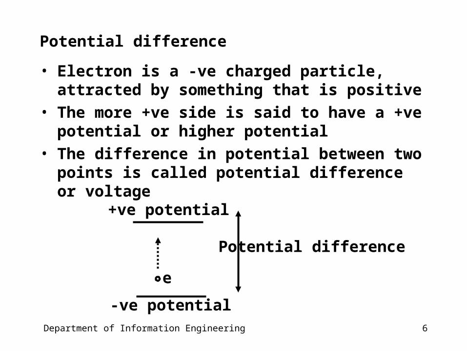
Potential difference
• Electron is a -ve charged particle, attracted by something that is positive
• The more +ve side is said to have a +ve potential or higher potential
• The difference in potential between two points is called potential difference or voltage
+ve potential
-ve potential
Potential difference
e

7Department of Information Engineering
Direction of Current
• By convention, current flows in opposite direction of electrons
– Electron flows from –ve (lower) potential to +ve (higher) potential
– current flows from higher potential to lower potential
+ve potential
-ve potential
e
current
8Department of Information Engineering
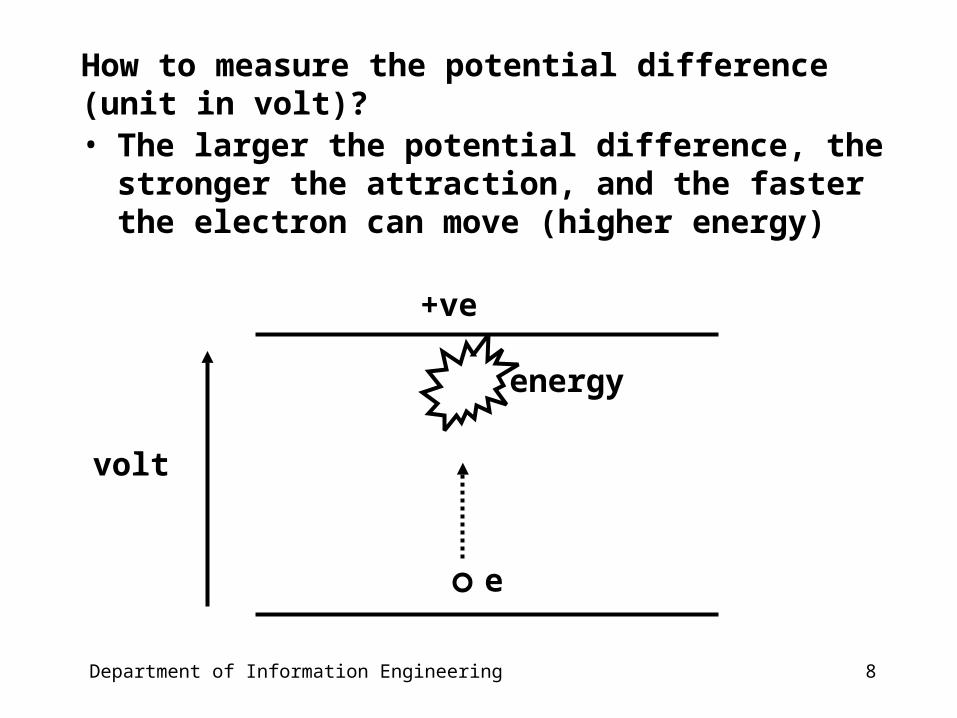
How to measure the potential difference (unit in volt)?
• The larger the potential difference, the stronger the attraction, and the faster the electron can move (higher energy)
volt
+ve
e
energy

9Department of Information Engineering
How to measure the potential difference?
• The total energy gained is proportional to the potential difference and the number of charges
• Energy (Joule) = potential difference (Volt) * charge
• Definition of 1 volt
– If the energy produced by 1 Coulomb of charge is 1 Joule, then the potential difference is 1 Volt
– Unit : Volt ( = Joule / Coulomb )

10Department of Information Engineering
Energy and Power
• Energy measures the total amount of work done
• Power measures how fast the energy is dissipated
– power = energy / time
• E.g. 1 J of energy is dissipated in 2 seconds,
– power = 0.5 J/s = 0.5 Watt
• Power = energy / time
= potential difference * charge / time
• Power = V * I

11Department of Information Engineering
Two-terminals device
• X can be a resistor, capacitor, or inductor
volt
Current in Current outX

12Department of Information Engineering
Voltage and Current
• Apply a voltage V to a two-terminals device, 3 possible outcomes
– Large current flow – X is a conductor
– Small current flow – X is a semiconductor
– No current flow – X is an insulator
• The ratio of voltage and current is a measure of the conductivity of the device
– If X is a resistor, then the ratio is called resistance
– If X is a capacitor/inductor, then it is called reactance
– If X is unspecified, then it is called impedance

13Department of Information Engineering
Voltage and Current
• Resistance R = V/I (unit Ohm)
• Or V = IR
V
I
This end denotes the reference point of the voltage measurement
R

14Department of Information Engineering
• Linear device
– Double the voltage, double the current
– The slope of V vs I is constant
• Non-linear device
– V vs I is not a straight line
I
V
LinearI
V
Non-linear
R

15Department of Information Engineering
• Linear devices
– Resistor (R)
• impedance is independent of frequency
– Inductor (L) and capacitor C
• Impedance is frequency-dependent
• Non-linear devices
– Anything other than RLC (resistor/inductor/capacitor)
– e.g. diode, transistor

16Department of Information Engineering
Water analogy

17Department of Information Engineering
V=IR (Ohm’s law)
• R = V / I
= 10V /0.1 A
= 100 ?
10V
I =0.1A
This end denotes the reference point of the voltage measurement

18Department of Information Engineering
100 watt light bulb
• Power = 100 W (each second dissipates 100 J)
• Power = VI, V=240V, therefore I = 100/240 A
• Resistance of the light bulb = V/I = 576
• To calculate power
– Power = VI, but since V=IR, therefore
– Power =2
2 VVI I R
R

19Department of Information Engineering
Circuit analysis
• Kirchhoff’s voltage law (KVL)
– Sum of voltage drops around any closed loop is zero
10V
100
V = 0

20Department of Information Engineering
What if the voltage drop around a loop is NOT zero?
• This would mean that a single point can have a potential difference !!
– Which is impossible
• Therefore the voltage drop around a loop MUST be zero

21Department of Information Engineering
Kirchhoff’s current law (KCL)
• sum of the currents flowing into a point equals the sum of the currents flowing out
– Conservation of charge, what goes in, must come out
321 III
1I
2I
3I
or
0321 III
1I
2I
3I

22Department of Information Engineering
Examples
• Resistors in series, what is R?
• Answer
– R = R1 + R2
=R1 R2 R ?

23Department of Information Engineering
Proof
• By KCL, current through the resistors are the same
• V = V1 + V2 = IR1 + IR2 = I ( R1 + R2 )
• therefore R = R1 + R2
=R1 R2 R ?
I
V
V1 V2

24Department of Information Engineering
Resistors in parallel
• Answer
–
V
I =
R1
R2
R ?I1
I2
21
21
RRRR
R
I
V
(remember this formula!)

25Department of Information Engineering
Proof
•
V
I =
R1
R2
R ?I1
I2
21
21
21
111RRR
RV
RV
RV
III
21
21
RRRR
R
I
V

26Department of Information Engineering
Common tricks
• Two equal resistors in parallel
R
R = ?
2R
Rtotal

27Department of Information Engineering
Common tricks
• Three equal resistors in parallel
R
= ?
3total
RR

28Department of Information Engineering
Common tricks
• Two very unequal resistors in parallel
– differ by a factor of 10 at least
R
10 RR
%101110
1010 2
error
RRR
RRtotal

29Department of Information Engineering
Common tricks
• Two very unequal resistors in series
– ignore the smaller resistor
• error is again less than 10%
– OK
– the tolerance of resistors is 5% - 10% anyway
R 10 R 10 R~
30Department of Information Engineering
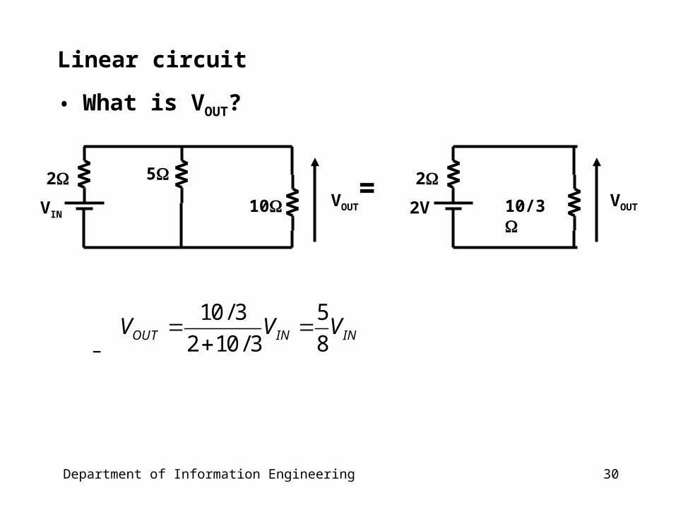
Linear circuit
• What is VOUT?
–
VIN
2
10 VOUT
5=
2V
2
10/3 VOUT
10 / 3 5
2 10 / 3 8OUT IN INV V V

31Department of Information Engineering
Linear circuit
• VOUT varies linearly with VIN
– Plot VOUT vs VIN, you get a straight line
• Resistive (and also capacitive and inductive) circuits are known as linear circuit because the output varies linearly with the input (energy source)
• If we have more than one energy source, linear circuits have the very useful property that the output is equal to the sum of all contributions from the energy sources
– Known as the Principle of Superposition

32Department of Information Engineering
What is VA?
• If you can solve this problem, you can solve any linear circuit problems
• Many different approaches, choose one you like– By KCL– By KVL– By the principle of superposition
2V 5V
2
10
a
VA
5

33Department of Information Engineering
By KCL
• Apply KCL to node ‘a’
2V 5V
2
10
a
VA
5
I1 I3
I2
1 2 3
2 5 0
2 5 102.5
A A A
A
I I I
V V V
V V

34Department of Information Engineering
You can define the direction of current in any way you like
2V 5V
2
10
a
VA
5
1 2 3 0
2 50
2 5 102.5
A A A
A
I I I
V V V
V V
I1 I3
I2

35Department of Information Engineering
By KVL
•
• I1 = -0.25A, I2=0.25A, VA=I2*10=2.5V
I1I2
2V 5V
2
10VA
5
1 1 2
2 1 2
2 2 5( ) 5 0
5 5( ) 10 0
I I I
I I I

36Department of Information Engineering
Principle of Superposition
• Output = sum of contributions from all energy sources
2V
2
10
5
2V 5V
2
10
5
5V
2
10
5+

37Department of Information Engineering
Principle of Superposition
• Contribution due to 2V source alone
– V1 = 1.25V
2V
2
10 V1
5=
2V
2
10/3 V1

38Department of Information Engineering
Principle of Superposition
• Contribution due to 5V source alone
– V2 = 1.25V
• VA = sum of contributions from 2 voltage sources
= V1 + V2
= 2.5V
5V
2
10V2
5
39Department of Information Engineering
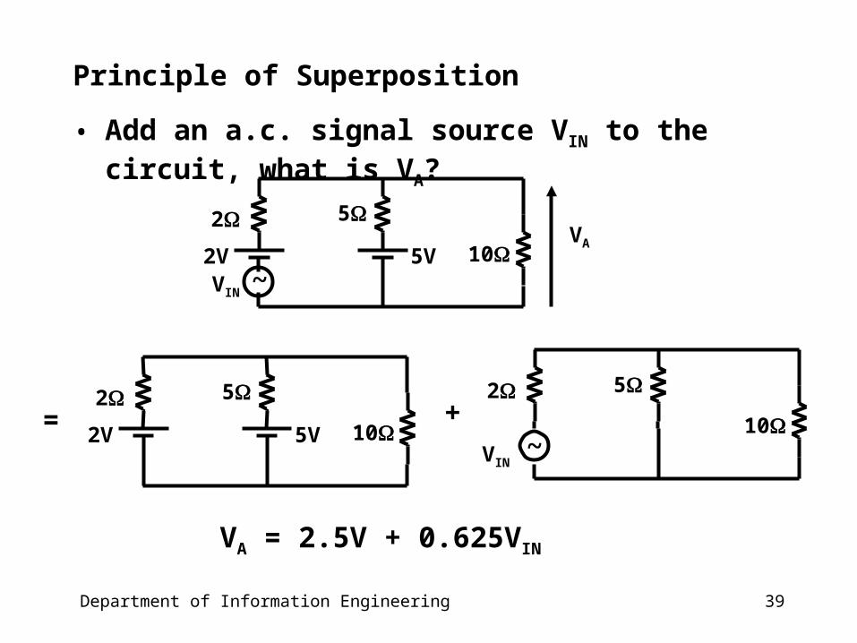
Principle of Superposition
• Add an a.c. signal source VIN to the circuit, what is VA?
2V 5V
2
10VA
5
~
2V 5V
2
10
5 2
10
5
~
VIN
VIN
+=
VA = 2.5V + 0.625VIN
40Department of Information Engineering
Linear system
• Linear circuit is an example of linear system
• Linear system is the most important model used in engineering
• What is a model?– A model is a simplification of the real world– We make this simplification (or approximation)
because the real world is too complicated– e.g. we model a complicated circuit by a number of
simpler circuits– Divide and conquer

41Department of Information Engineering
Linear system
• You make this linear assumption everyday
– The sound you hear,
– and the light you see,
– are the sum of contributions from individual energy sources
speakerspeaker
Total intensity = sums of individual contributions

42Department of Information Engineering
Non-linear system
• Example–
– The plot of VOUT vs VIN is non-linear
• For a non-linear system
– The output is NOT equal to the sum of contributions from individual energy sources
– Can’t simplify the it by the principle of superposition
• How to solve it?
2OUT INV aV

43Department of Information Engineering
Small signal model
• Assume the change of VIN (VIN)is small, so that the non-linear part can be approximated by a straight line
– VOUT = k VIN
VIN
VOUT
VIN
VOUT Approximately linearSlope = k
2OUT INV aV
44Department of Information Engineering
Large signal model
• Difficult to solve in general
– e.g weather forecast involves non-linear equations
• Can be solved by computer simulation (using supercomputers!)
45Department of Information Engineering
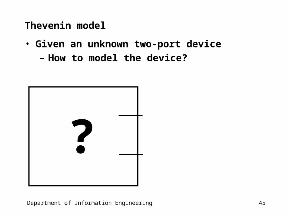
Thevenin model
• Given an unknown two-port device
– How to model the device?
?

46Department of Information Engineering
Thevenin model
• Any linear circuit can be simplified to a voltage source VThev and an impedance RThev
=VThev
RThev?

47Department of Information Engineering
A proof of Thevenin theorem
• VA = sum of contributions from all energy sources
VA
R
The unknown device

48Department of Information Engineering
Apply superposition to the circuit
+ . . . +
R
R R
VA

49Department of Information Engineering
• But if R is changed, we have to repeat the tedious calculation
• A simpler model for calculation
– Model the output by adding a current source

50Department of Information Engineering
• The unknown circuit still sees the same current I
VAR VA
I I

51Department of Information Engineering
What is an ideal voltage source ?
• A source that has constant voltage, but zero impedance
• V vs I plot
– The slope (V/I) is zero
• Increase in current, no change in voltage
– zero impedance
– (or R=dV/dI = 0)
V
I

52Department of Information Engineering
What is an ideal current source?
• A source that gives out constant current
• V vs I plot
– The slope (V/I) is infinite
– dV/dI = infinite
• Or a tiny increase in current causes infinite change in voltage
– Behaves as if it has infinite impedance
V
I

53Department of Information Engineering
Divide the complex circuit into many simpler circuits
•
+ . . . +
I
VA = a1V1 + . . . + anVn+ an+1I
IV1
I
VA
54Department of Information Engineering
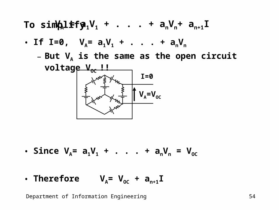
To simplify
• If I=0, VA= a1V1 + . . . + anVn
– But VA is the same as the open circuit voltage VOC !!
• Since VA= a1V1 + . . . + anVn = VOC
• Therefore VA= VOC + an+1I
VA = a1V1 + . . . + anVn+ an+1I
I=0
VA=VOC

55Department of Information Engineering
• What is an+1?
– All resistors can be combined into one
• So that VA (due to I) = an+1I = RThev * I
• VA = a1V1 + . . . + anVn+ an+1I
= VOC + RThev*I
I IRThevVAVA

56Department of Information Engineering
• VA= VOC + RThev*I
• RThev = Output Impedance
I
VOC
RThevVA

57Department of Information Engineering
Given a black box, how to find VThev and RThev ?
VThev
RThev
VThev = VOC
RThev = VOC / ISC
(VOC= open circuit voltage)(ISC = short circuit current)

58Department of Information Engineering
A more practical way to find RThev
• Short circuit current may damage your circuit
• Use a resistor to measure RThev
•
I
OC
Thev
V VR
I
VOC
RThev
V

59Department of Information Engineering
Thevenin model by calculation
• VOC = 20/7 V
• ISC = 2A
• Therefore RThev = 10/7
2V 5V
2ISC
5VOC

60Department of Information Engineering
Use of Thevenin model
• Output is connected to a 10 resistor, what is VA?
•
20/7 V
10VA10
VA
2V 5V
2 5
107
10 20* 2.5
10 7aV V V

61Department of Information Engineering
Advantage of using Thevenin model
• VA can be found easily for different load
– VA =
RVA
20/7 V
2010 7
RR

62Department of Information Engineering
Voltage divider
• Important concepts
– input impedance
– output impedance
– loading effect
• First, what is VOUT?
– VOUT =
= VIN / 2 = 15V
VOUT10
10 10 IN
kV
k k
63Department of Information Engineering
Voltage divider
• Is this a good voltage divider?
– A good voltage divider should
behave like an ideal voltage source
– Provides constant voltage
• Is this the case?
64Department of Information Engineering
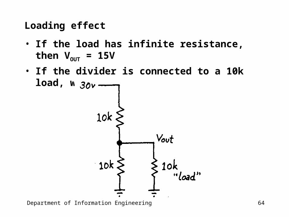
Loading effect
• If the load has infinite resistance, then VOUT = 15V
• If the divider is connected to a 10k load, what is VOUT?

65Department of Information Engineering
• VOUT = VIN (5k/15k) = VIN / 3
= 10V (a big drop from 15V!)

66Department of Information Engineering
• The divider is droopy
– output voltage is load-dependent, it is not a good voltage divider
• Ideal divider should be stiff
– output voltage is constant over a wide range of load
• How to build a better divider?

67Department of Information Engineering
Thevenin model
(30v)
(10k)
(10k)
(5K)
15V

68Department of Information Engineering
Applying the Thevenin model
• If RLoad = 10k, then VOUT = VThev (10k/15k) = 10V

69Department of Information Engineering
Output impedance RThev
• RThev is the resistance as seen by the outside world
– the output impedance of the circuit
– a very important parameter
=complexcircuit
External world seesa simple resistor

70Department of Information Engineering
Fast way to calculate RTh
• remove all energy sources
– Replace voltage source by short circuit
– Replace current source by open circuit
• RTh is the resistance viewed from the output
71Department of Information Engineering
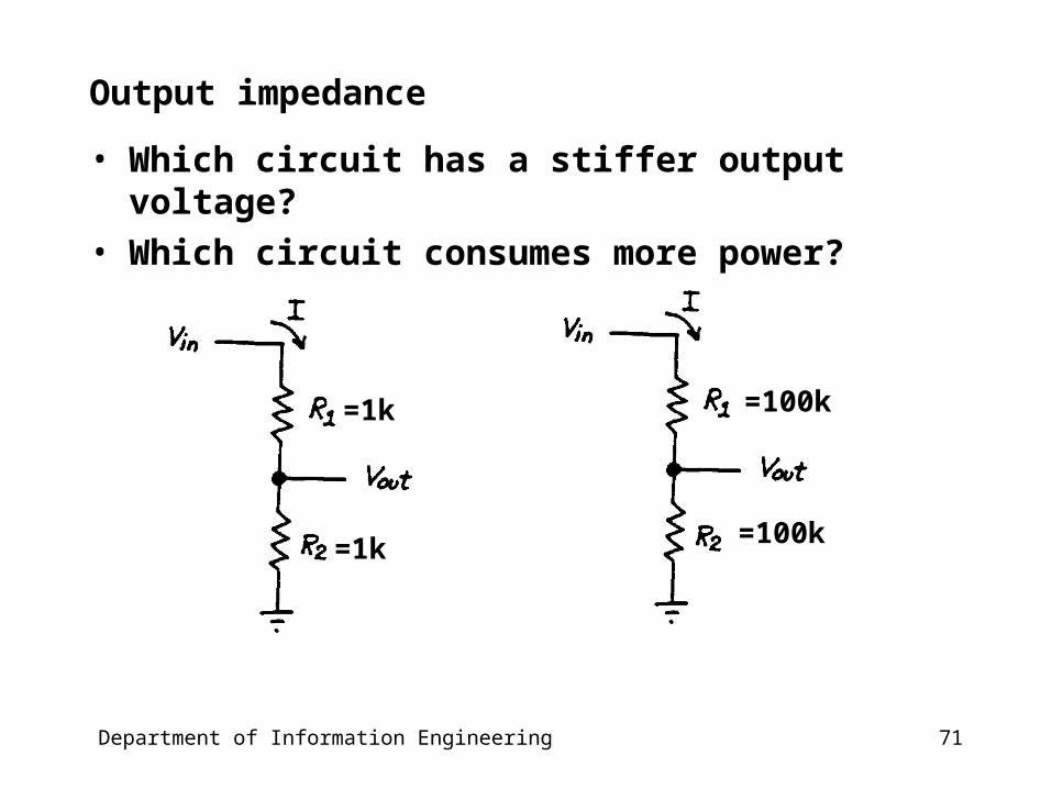
Output impedance
• Which circuit has a stiffer output voltage?
• Which circuit consumes more power?
=1k
=1k =100k
=100k

72Department of Information Engineering
A general model for any linear circuit
• Input impedance and output impedance
– Input impedance = VIN / IIN
– Output impedance = RThev
Linear CircuitVIN
IIN
VOUT
IOUT
73Department of Information Engineering
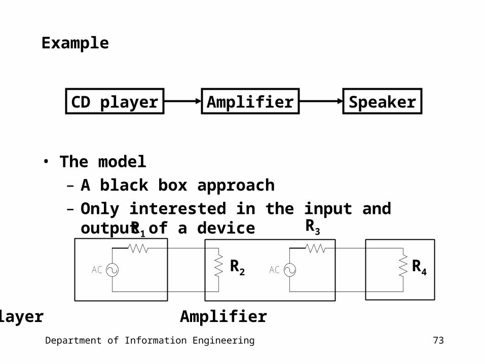
Example
• The model
– A black box approach
– Only interested in the input and output of a device
CD player Amplifier Speaker
AC AC
CD player Amplifier Speaker
R1
R2
R3
R4

74Department of Information Engineering
CD to amplifier
• Output signal of CD player
– V1, measured in voltage
• Input signal to amplifier
– V2, measured in voltage
AC AC
R1
R2V1 V2
CD player Amplifier
75Department of Information Engineering
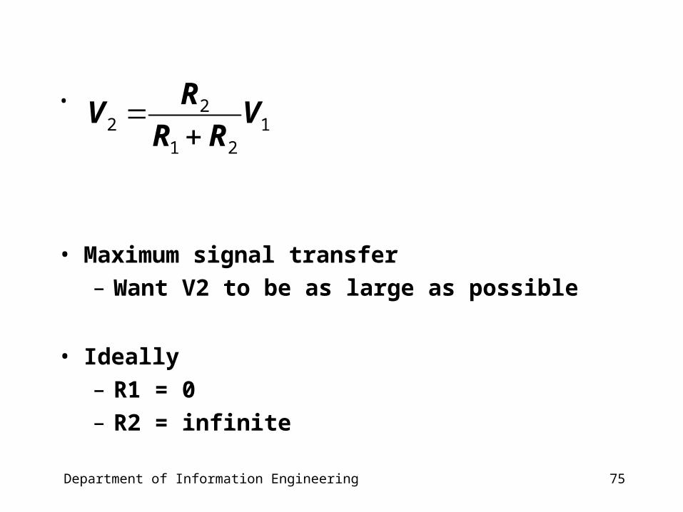
•
• Maximum signal transfer
– Want V2 to be as large as possible
• Ideally
– R1 = 0
– R2 = infinite
22 1
1 2
RV V
R R

76Department of Information Engineering
Amplifier to speaker
• Maximum power transfer
– Speaker needs energy to produce loud sound
– Power = V4*I
AC
R3
R4V3 V4
I
Amplifier Speaker

77Department of Information Engineering
• If R4 = infinite
– Large V4, but I=0 !
– Power = 0
• If R4 = 0
– Large I, but V4=0 !
– Power =0
• So R4 cannot be too large nor too small
• For maximum power transfer, R3 = R4
– Try to prove this yourself

78Department of Information Engineering
Five voltage dividers, which one is the best?

79Department of Information Engineering
An imperfect voltmeter
• The voltmeter is not perfect because it has finite input impedance RIN
• From the following measurements, what is RIN?

80Department of Information Engineering
Input impedance of analog voltmeter
• If R=100k, the measured voltage is only 8.05V
– 2V is dropped across 50k, 8V is dropped across RIN,
– therefore RIN = 50k*4 = 200k

81Department of Information Engineering
• In general, if the load = RLOAD, then
• This is important !!
– Good voltage divider should have RThev much smaller than RLOAD
– But how small?
Thev
LOADOUT
Thev LOAD
RV V
R R

82Department of Information Engineering
The 10X design rule
• Input impedance of B should be at least 10 times larger than the output impedance of A

83Department of Information Engineering
10X design rule
• If ROUT,A is 10 times smaller than RIN,B
– then B receives at least 90% of the signal, the loss is less than 10%, acceptable
• More importantly, the input impedance of B is large enough to be treated as if it is an open circuit
– Simpler calculation, no need to need the circuit of B
Circuit A
Input impedanceof circuit B RIN,B > 10 ROUT,A
ROUT,A

84Department of Information Engineering
Colour code of resistor

85Department of Information Engineering
• Why it is important to make sure circuit B can be treated as if it is an open circuit?
• Because this is the assumption we always make in circuit analysis !
– that the output is an open circuit
Vin Vout

86Department of Information Engineering
VOUT of stage B?
• What is the output impedance of circuit A?
• What is the input impedance of circuit B?

87Department of Information Engineering
VOUT of stage B?
• Input impedance of B is 10 times the output impedance of A
– Loading effect is negligible (10X rule)
– VOUT ~ VIN
• Accurate result
– VOUT = VIN
• The error is less than 10% , OK
44
10
1 12 2

88Department of Information Engineering
The use of 10X rule
• 10X rule follows the most important design principle in engineering
– Divider and conquer
– Divide a complex circuit into many simple circuits

89Department of Information Engineering
A complex circuit = sum of simple circuits

90Department of Information Engineering
Lab equipments
• Function generator
– generate common waveforms for testing purposes
• sine wave
• square wave
• triangular (ramp) wave
• you can vary the signal’s amplitude and frequency
• Oscilloscope
– Enable us to see the periodic signal

91Department of Information Engineering
Oscilloscope’s control
• Vertical control
– use to magnify the displayed signal
Magnify the displayed signal
One vertical division

92Department of Information Engineering
Vertical control for channel 1e..g 20mV/DIVif signal amplitude=2.5 DIVamplitude = 50mV
Select which channel to display
Adjust the positionof the displayed signal
Input socket for channel 1

93Department of Information Engineering
• Coupling
– dc
– GND
– ac
• GND (this means Ground level)
– display the ground (0V) signal (appear as a straight line on the scope)
– for beginner : always set vertical to GND first so as to find the position of 0V
94Department of Information Engineering
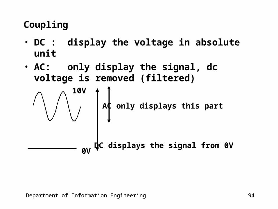
Coupling
• DC : display the voltage in absolute unit
• AC: only display the signal, dc voltage is removed (filtered)
0V
10V
AC only displays this part
DC displays the signal from 0V

95Department of Information Engineering
Horizontal control
• Changing the time/DIV allows you to expand or to compress the signal waveform horizontally
96Department of Information Engineering
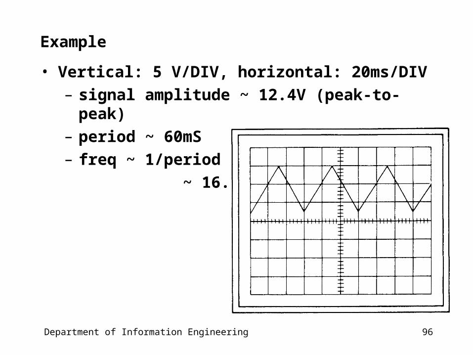
Example
• Vertical: 5 V/DIV, horizontal: 20ms/DIV
– signal amplitude ~ 12.4V (peak-to-peak)
– period ~ 60mS
– freq ~ 1/period
~ 16.6 Hz

97Department of Information Engineering
Trigger
• trigger is a sequence of short sync pulses that tell the scope to start displaying the signal
– if the timing signal is not correct, you see a mess
Irregular triggering pointsScope start sweeping at wrong time
You see a mess
trigger pulse

98Department of Information Engineering
Triggering
• Correct trigger gives a clean display
correct triggerstart horizontal sweepat the right time
Clean displayWhat you see is the overlapping of many sweep lines
Sync pulse

99Department of Information Engineering
Triggering
• The control panel

100Department of Information Engineering
Where to get the triggering signal?
• External trigger– e.g. if the sine wave is generated by a function
generator, then you can use the SYNC output of the function generator as the triggering signal
– The best way to get the triggering signal
• Internal trigger– Extracted from the input signal based on
• slope• level
– Less clean, but often used because reliable external trigger cannot be found
101Department of Information Engineering
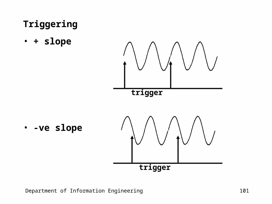
Triggering
• + slope
• -ve slope
trigger
trigger

102Department of Information Engineering
Triggering
• + (higher level)
• -ve (lower level)
Trigger on +ve leveland +ve slope
Trigger on -ve leveland -ve slope

103Department of Information Engineering
Triggering
• Trigger coupling
– dc : trigger based on the dc signal
– ac: trigger based on the ac signal ( i.e. only use the varying part); the usual choice
– LF REJ: derived the trigger signal from the input signal after the low frequency (LF) part is removed
– HF REJ: derived the trigger signal from the input signal after the high frequency (HF) part is removed