department of the air force qtp24-3-l143 headquarters …
TRANSCRIPT

DEPARTMENT OF THE AIR FORCE Headquarters US Air Force
QTP24-3-L143 26 March 2019
Washington, D.C. 20330-1030
P-23 High Reach Extendable Turret (HRET) Oshkosh 3000 StrikerVehicle Management Codes: L143
QUALIFICATION TRAINING PACKAGE
Contents SECTION 1—OVERVIEW ........................................................................................................................................ 3
1.1. Overview. ................................................................................................................................................................................................. 3
SECTION 2—RESPONSIBILITIES ......................................................................................................................... 3
2.1. Responsibilities. ....................................................................................................................................................................................... 3
SECTION 3—INTRODUCTION .............................................................................................................................. 4
3.1. Objectives. ............................................................................................................................................................................................... 4
3.2. Desired Learning Outcome. ................................................................................................................................................................... 5
3.3. Lesson Duration. ..................................................................................................................................................................................... 5
3.4. Instructional References. ........................................................................................................................................................................ 5
3.5. Instructional Training Aids and Equipment. ........................................................................................................................................ 6
SECTION 4—TRAINEE PREPARATION .............................................................................................................. 7
4.1. Licensing Requirements: ........................................................................................................................................................................ 7
4.2. Required Reading (Testable Material). ................................................................................................................................................. 7
SECTION 5—KNOWLEDGE LECTURE AND EVALUATION .......................................................................... 7
5.1. Knowledge Overview (Lecture).............................................................................................................................................................. 7
5.2. Overview of Training and Requirements. ............................................................................................................................................. 8
5.3. Vehicle Inspection. ................................................................................................................................................................................ 17
5.4. Vehicle Safety and Equipment. ............................................................................................................................................................ 21
5.5. Driving Safety and Precautions. ........................................................................................................................................................... 22
5.6. P-23 Oshkosh 3000 Striker Vehicle Operation. .................................................................................................................................. 25
5.7. Firefighting Systems Operation. .......................................................................................................................................................... 31
5.8. Post-Operational Procedures (Re-Servicing). ..................................................................................................................................... 43
5.9. Structural System Operation. .............................................................................................................................................................. 43
5.10. Re-servicing the Water/Foam Tanks. .................................................................................................................................................. 49
5.11. Dry Chemical System. ........................................................................................................................................................................... 51
5.12. Transportability. ................................................................................................................................................................................... 55
SECTION 6—EXPLANATION AND DEMONSTRATION ................................................................................ 59
6.1. Instructor’s Preparation: ..................................................................................................................................................................... 59
6.2. Safety Procedures and Equipment: ..................................................................................................................................................... 59
6.3. Operator Maintenance Demonstration................................................................................................................................................ 60
6.4. Operation Demonstration. .................................................................................................................................................................... 60
SECTION 7—TRAINEE PERFORMANCE AND EVALUATION .................................................................... 62
7.1. Trainee Performance. ........................................................................................................................................................................... 62
7.2. Performance Evaluation. ...................................................................................................................................................................... 65
Attachment 1—GLOSSARY OF REFERENCES AND SUPPORTING INFORMATION 71 Attachment 2—SUBJECT KNOWLEDGE 73 Attachment 3—VEHICLE INSPECTION GUIDE 87 Attachment 4—PERFORMANCE TEST 91 Attachment 5—OPERATION & TROUBLESHOOTING GUIDE FOR THE AIR FORCE IDLE REDUCTION TECHNOLOGY
(IRT) SYSTEM 94 Attachment 6—SEVEN-STEP INSPECTION PROCESS 98

Section 1—OVERVIEW 1.1. Overview.
1.1.1. Send comments and suggested improvements on AF Form 847, Recommendation for Change of Publication through Air Force Installation and Mission Support Center (AFIMSC) functional managers via e-mail at [email protected]. 1.1.2. How to use this plan:
1.1.2.1. Instructor:
1.1.2.1.1. Provide overview of training, Section 2 and Section 3. 1.1.2.1.2. Instructor’s lesson plan for trainee preparation, give classroom lecture, Section 4. 1.1.2.1.3. Instructor’s lesson plan for knowledge test, Section 5. 1.1.2.1.4. Instructor’s lesson plan for demonstration, Section 6. 1.1.2.1.5. Instructor’s lesson plan for performance and evaluation, Section 7.
1.1.2.2. Trainee:
1.1.2.2.1. Reads material entire lesson plan prior to classroom lecture. 1.1.2.2.2. Follows along with lecture using this lesson plan and its attachments. 1.1.2.2.3. Takes P-23 Oshkosh 3000 Striker knowledge test. 1.1.2.2.4. Uses Attachment 3 as a guide for vehicle inspection. 1.1.2.2.5. Takes performance test, Attachment 4.
Section 2—RESPONSIBILITIES 2.1. Responsibilities.
2.1.1. The trainee shall:
2.1.1.1. Ensure the trainer explains the lesson plan process and the responsibilities. 2.1.1.2. Review the lesson plan/module/unit and the manufacturer’s operator’s manual with the trainer.
2.1.1.3. The trainee should ask questions if he/she does not understand the objectives for each unit. 2.1.1.4. Review missed questions with the trainer.
2.1.2. Instructor shall:
2.1.2.1. Review the lesson plan with the trainee. 2.1.2.2. Conduct knowledge training with the trainee using the lesson plan. 2.1.2.3. Grade the review questions using the answer key. 2.1.2.4. Review missed questions with the trainee to ensure the required task knowledge has been gained to complete the task. 2.1.2.5. Sign-off the task(s).
2.1.3. The Certifier shall:
2.1.3.1. Evaluate the Airman’s task performance without assistance. 2.1.3.2. Sign-off the task(s).
Section 3—INTRODUCTION 3.1. Objectives.
3.1.1. Given lectures, demonstrations, hands-on driving session and a performance and written test, trainees will be able to perform operator’s inspection and complete the performance test with zero instructor assists and achieve 80% on the written test. The written test for the P-23 Oshkosh 3000 Striker is located on the Civil Engineering Virtual Learning Center (CE-VLC).
3.1.1.1. Train and qualify each trainee in inspection, safe operation, preventive maintenance and resupply of the P-23 Oshkosh 3000 Striker. 3.1.1.2. This training will ensure the trainee becomes a qualified P-23 Oshkosh 3000 Striker operator; an operator who has the knowledge and skills to operate the P-23 Oshkosh 3000 Striker in a safe and professional manner. 3.1.1.3. Familiarize licensed personnel in the inspection, operation, and resupply of the P-23H. 3.1.1.4. Train F&ES personnel in the use of the HRET (Snozzle®) of the P-23H Oshkosh 3000 Striker.

3.2. Desired Learning Outcome.
3.2.1. Understand the safety precautions to be followed before-, during-, and after-operation of the P-23 Oshkosh 3000 Striker. 3.2.2. Understand the purpose of the P-23 Oshkosh 3000 Striker and its role in the mission. 3.2.3. Know the proper operator maintenance procedures of the P-23 Oshkosh 3000 Striker, in accordance with (IAW) applicable technical orders (TOs) and use of AF Form 1800, Operator’s Inspection Guide and Trouble Report. 3.2.4. Safely and proficiently operate the P-23 Oshkosh 3000 Striker.
3.3. Lesson Duration.
3.3.1. Recommended instructional and hands on training time is 25 hours:
Figure 3.1. Recommended Training Time for Training Activities.
Training Activity Training Time
Manual Study 4 Hours
Daily Check-out 5 Hours
Operations 16 Hours
Note: This is a recommended time; training time may be more or less depending how quickly a trainee learns new tasks.
3.4. Instructional References.
3.4.1. Risk Management (RM) and Safety Principles. 3.4.2. Applicable – 1 TOs or Manufacturer’s Operator’s Manual (see vehicle maintenance for TO number for vehicle being used in training). 3.4.3. Air Force Manual (AFMAN) 24-306, Operation of Air Force Government Motor Vehicles. 3.4.4. AF Form 1800.

3.4.5. Code of Federal Regulations (CFR), Title 49—Transportation, Subtitle B—Other Regulations Relating to Transportation (Continued), Chapter III—Federal Motor Carrier Safety Administration, Department of Transportation, parts 300-399; on-line at http://www.access.gpo.gov/nara/cfr/cfr-table-search.html. 3.4.6. United States Department of Transportation, Federal Motor Carrier Safety Administration (FMCSA); on-line at http://www.fmcsa.dot.gov/index.htm. 3.4.7. Part No. OM-T-OM660-1113 Oshkosh Striker Operator’s Manual. 3.4.8. Part No. OM-A-OM690-1013 Oshkosh Snozzle® Aircraft Rescue Fire Fighting (ARFF) Model 501/651 Operator’s Manual. 3.4.9. Oshkosh Striker Service Manual for vehicle identification number (VIN) Number: 770873. 3.4.10. International Fire Service Training Association (IFSTA), Aircraft Rescue and Firefighting, Fifth Edition. 3.4.11. Career Development Course (CDC) 10027, Driver/Operator ARFF Performance Test. 3.4.12. NFPA 1002, Standard for Fire Apparatus Driver/Operator Professional Qualifications. 3.4.13. NFPA 1003, Standard for Airport Fire Fighter Professional Qualifications. 3.4.14. NFPA 1041, Standard for Fire Service Instructor Professional Qualifications. 3.4.15. NFPA 1403, Standard on Live Fire Training Evolutions. 3.4.16. NFPA 1500, Standard on Fire Department Occupational Safety and Health Program.
3.5. Instructional Training Aids and Equipment.
3.5.1. P-23 Oshkosh 3000 Striker Lesson Plan. 3.5.2. P-23 Oshkosh 3000 Striker. 3.5.3. Applicable TO or manufacturer’s operator’s manual. 3.5.4. AF Form 1800. 3.5.5. Part No. OM-T-OM660-1113 Oshkosh Striker Operator’s Manual.
3.5.6. Part No. OM-A-OM690-1013 Oshkosh Snozzle® ARFF Model 501/651 Operator’s Manual. 3.5.7. Oshkosh Striker Service Manual for VIN Number: 770873. 3.5.8. IFSTA Aircraft Rescue and Firefighting, Fifth Edition. 3.5.9. CDC 10027, Driver/Operator ARFF Performance Test. 3.5.10. Videos (if locally produced). 3.5.11. Suitable training area. 3.5.12. Traffic cones.
Section 4—TRAINEE PREPARATION 4.1. Licensing Requirements:
4.1.1. Trainee must have in his/her possession a valid state driver’s license. 4.1.2. AF Form 171, Request for Driver’s Training and Addition to U.S. Government Drivers IAW Air Force Instruction (AFI) 24-301, Ground Transportation. 4.1.3. Applicable local licensing jurisdiction requirements.
4.2. Required Reading (Testable Material).
4.2.1. Read this lesson plan in its entirety. 4.2.2. Read AFMAN 24-306. 4.2.3. Read manufacturer’s operator’s manual for the vehicle being trained on.
Section 5—KNOWLEDGE LECTURE AND EVALUATION 5.1. Knowledge Overview (Lecture).
5.1.1. The majority of the material below was written using the instructional references listed in Section 3. They have been expanded upon and modified to address the knowledge needs in accordance the role of the Vehicle Operator under the mission and standards required by the United States Air Force.

5.2. Overview of Training and Requirements.
5.2.1. Training objectives:
5.2.1.1. Given lectures, demonstrations, hands-on driving session and a performance and written test, trainees will be able to perform operator’s inspection and complete the performance test with zero instructor assists and achieve 80% on the written test on the CE-VLC. 5.2.1.2. Train and qualify each trainee in safe operation and preventive maintenance of the P-23 Oshkosh 3000 Striker. 5.2.1.3. This training will ensure the trainee becomes a qualified P-23 Oshkosh 3000 Striker operator—an operator who has the knowledge and skills to operate a P-23 Oshkosh 3000 Striker in a safe and professional manner.
5.2.2. Desired learning outcome:
5.2.2.1. Understand the safety precautions to be followed before, during, and after operation of the P-23 Oshkosh 3000 Striker. 5.2.2.2. Understand the purpose of the P-23 Oshkosh 3000 Striker and its role in the mission.
5.2.2.2.1. Purpose is to combat aircraft fire in all weather conditions. 5.2.2.2.2. Role in the mission: Unit, Base, Community (during natural disasters), and Air Force.
5.2.3. Specifications. For vehicle specifications, see Attachment 2, the P-23 Oshkosh 3000 Striker Power Point and P-23 Oshkosh 3000 Striker manufacturer’s operator’s manual. 5.2.4. P-23 Oshkosh 3000 Striker Design Overview:
5.2.4.1. The P-23 Oshkosh 3000 Striker has a diesel engine powered, 6x6 all-wheel drive chassis. A single diesel engine powers the truck drive train and water pump. 5.2.4.2. The firefighting systems of the truck are self- sufficient. No outside source for extinguishing agents is needed. The truck contains a pressure pump and firefighting equipment. Water, foam, and dry chemical are carried in tanks built into the truck body. 5.2.4.3. The truck body is insulated, preventing heat loss from the truck interior during cold weather. The insulation also provides protection from fire heat. Water or a combination of water and foam can be used to put out a fire.

5.2.4.4. Agents are delivered through the cab-mounted roof turret, the bumper turret, or the hand line. These can be used alone or at the same time. The dry chemical system uses its own hand line, or can be utilized in the bumper or roof turrets as both dry and wet chemical modes of operation. 5.2.4.5. The chassis design allows the truck to operate in all weather and on off-road terrain. The truck is equipped with Class II winterization equipment. This allows the truck to maintain standby status in cold weather without running its engine.
5.2.5. P-23 Oshkosh 3000 Striker Components. 5.2.5.1. Engine. The P-23H is powered by a Deutz TCD V8 diesel engine. This engine is equipped with a turbocharger and an after cooler for smooth, powerful operation. The maximum torque is 2,131 foot-pounds at 1,400 revolutions per minute (rpm). 5.2.5.2. Transmission. The transmission is an Allison 4800 EVS that provides seven speeds forward and one reverse.
5.2.5.2.1. It must be manually shifted into and out of first range. The remaining ranges automatically up shift and downshift. 5.2.5.2.2. An integral torque converter transmits power from the power divider to the transmission gearing. The torque converter is provided with an automatic lock-up clutch effective in all forward ranges.
5.2.5.3. Power Divider. The Oshkosh power divider is located between the engine and the transmission, and makes engine power available to the water pump and to any installed hydraulic accessories.
5.2.5.3.1. When the water pump clutch is engaged, engine power is redirected to the water pump via a driveshaft. Under most firefighting conditions, all engine power is routed to the water pump and none is available to the transmission. 5.2.5.3.2. In Pump and Roll mode, the power divider clutch is modulated by the powertrain control system according to an algorithm based on throttle position, engine speed, and vehicle speed. Vehicle travel is then possible at reduced speed while the water pump operates and firefighting operations are underway. 5.2.5.3.3. In the event of a system failure, the main power divider clutch will fail to engaged to allow the vehicle to leave the emergency or to return to station for service.
5.2.5.4. Transfer Case. The vehicle driveline consists of an automatic transmission, transfer case, single front driving axle and rear driving axle(s). Each axle differential is equipped with an inter-axle locking mechanism. The transfer case interaxle differential is also equipped with a driver selected locking mechanism.
5.2.6. Suspension:
5.2.6.1. Suspension. The Oshkosh TAK-4 Independent Suspension System consists of Dual Control Arms and Single Coil Springs. It allows for up to 16 inches (40.6 cm) of Wheel End Travel.
5.2.6.2. Front Axle. The 31,000 lb (13,152 kg) Oshkosh Double- Reduction Front Axle is equipped with Bevel Gear Differential and Driver Operated Differential Locks (To traverse and separate front-to- back). 5.2.6.3. Rear Axle. The rear axles are 2 x 31,000 lb (2 x 14,090 kg) and 62,000 lb (28,182 kg) Oshkosh Double-Reduction axles equipped with Bevel Gear Differential, and Driver Operated Differential Locks. 5.2.6.4. Differential Locking System. The differential locking system permits the driver to simultaneously lockup the differential in the transfer case and the inter-axle differential in the rear axles; and it engages the controlled traction differentials in all axles.
5.2.6.4.1. The differential locking system is activated by a rotary switch mounted on the lower left dash panel. 5.2.6.4.2. When disengaged, it restores full differential action to give the driver easy, normal steering control for normal road conditions. The controlled traction differential only limits differential action. It does not lock the differential.
5.2.6.5. Wheels and Tires. The six tubeless tires are all Michelin 24R21 XZL mounted on 21x18x3.75 rims and have a cold tire inflation pressure of 95 pounds per square inch (psi) (586 kPa).
5.2.7. Brakes. This truck uses a dual air brake system for the service brakes and is equipped with an Anti-Lock Braking System (ABS).
5.2.7.1. This means that if one system has lost pressure, the other system will have sufficient pressure for a limited number of brake applications. An alarm will sound and a light will illuminate if air pressure in either system drops below the minimum necessary. 5.2.7.2. The instrument cluster on the left hand center cab instrument panel has two gauges. The left side gauge indicates air pressure present in the front brake system. 5.2.7.3. The right gauge displays rear service brake system air pressure. During normal conditions, the spring brakes will only apply when the parking brake is applied. However, if the rear service brake system pressure drops below 65 psi (448 kPa), a control valve will automatically switch the operation of the spring brakes to replace the service brakes.

5.2.7.4. When the operator depresses the brake treadle valve and the rear service brake air pressure is below 65 psi (448 kPa), the front brakes and the spring brakes will apply.
5.2.8. Air System. The major components of the Striker compressed air system include an engine-driven compressor, an air dryer, and three cylindrical air tanks located on the vehicle’s underside. These tanks store compressed air for use by the vehicle’s various systems, with first priority to the braking system. 5.2.9. It is recommended that the air tanks be purged daily to check for fluid or contamination. It is not necessary to completely drain all of the air from the tanks. Drain valves are located below equipment compartment L3, immediately forward of the rear wheel(s).
5.2.10. Electrical System. The electrical system of the Striker 3000 HRET makes 12- and 24-Volt power available for vehicle and customer equipment.
5.2.10.1. The 12 volt system uses 12 volt batteries connected in parallel. The 24 volt system uses 12 volt batteries connected in series. For this reason, the usual positive (+) and negative (-) naming convention and colors do not apply for this vehicle.
5.2.10.2. Batteries. Four 12-Volt batteries supply the necessary power. 5.2.10.3. Alternator. The vehicle is equipped with two (2) 24V 110A engine. 5.2.10.4. External Receptacles. Two types of external power receptacles are provided at the rear of the vehicle.
5.2.10.4.1. When the engine is shut down, a 24 volt plug-in receptacle will accept power from an auxiliary power source to recharge the batteries and operate the vehicle electrical system. 5.2.10.4.2. It can also be used as an output to power 24 volt accessory equipment and to jump start other vehicles. The 120 volt, 20 amp or 230 V, 20 amp receptacles when connected to an external power source, supplies power to the battery charger which converts alternating current to direct current. 5.2.10.4.3. The equipment compartment R1 may contain various options to include an electrical cord reel for external equipment usage.

5.2.10.5. Winterization System. The Winterization (Compartment Heater) System heats the compartments prevents freezing of the water in the agent tank and firefighting system prevent piping from freezing when operating in cold conditions. The aluminum body and cab are also insulated to prevent loss of heat during cold weather operation.
5.2.10.5.1. The Winterization (Compartment Heater) System consists of a diesel fuel burning heater in a piping system which circulates the heated coolant around discharge piping and through various storage compartments in the vehicle body structure. 5.2.10.5.2. Heat exchangers in the center compartments provide forced air heat (convection heat) from the heated coolant supply to maintain compartment temperature above the freezing point of water. 5.2.10.5.3. A recirculating pump is provided in the system to maintain a constant flow of heated coolant to all parts of the system. 5.2.10.5.4. The winterization (compartment) heater is a 16,000 W fuel-burning unit, mounted in the right side maintenance compartment. Coolant is circulated through the water jacket and heated by the burning mixture of diesel fuel and air inside the combustion chamber. 5.2.10.5.5. Fuel for the heater is drawn from the vehicle fuel tank by an electric fuel pump on the heater. 5.2.10.5.6. The piping heater is switched on and off by means of a rocker switch located on the lower left dash switch panel.
5.2.10.5.6.1. An operation indicator light shows if the heater is operating. Whenever the heater is switched off, a running down process takes place, during which it is possible to switch the heater on again.
5.2.11. Fuel System. The fuel system consists of a 90 gallon (gal) fuel tank, priming pump, lines, fuel/water separator, fuel injection pump, and fuel injectors.
5.2.11.1. The fuel tank is mounted inside a compartment at the left rear of the truck. A priming pump is located in the same compartment. A fuel filter/water separator unit is mounted in the left maintenance access compartment.
5.2.12. Firefighting System. The firefighting system electronically controls the various components of the vehicle and its firefighting tools. It is designed to discharge water or foam without interruption while the vehicle is stationary, in motion, or maneuvering over rough terrain. The firefighting system is capable of controlling engine speed to manage water pump pressure and other vehicle- powered systems.
5.2.12.1. The operator may manually adjust engine speed or specify a pressure for the system to control to. Output pressure will be maintained as discharges are activated and deactivated. 5.2.12.2. Firefighting system discharge controls are arranged on the right dash panel to be operated by either the driver or an operator. Depressing the upper portion of the WATER or FOAM mode switch on the right dash panel signals the power divider to engage its clutch and drive the water pump, which runs at a speed proportional to engine speed. 5.2.12.3. In structural mode, pump speed and pressure can then be manually adjusted at the structural panel. If automatic speed adjustment is selected, the system will adjust engine speed automatically to control for a water pump output pressure. 5.2.12.4. When a discharge outlet (i.e. turret, undertruck nozzles, etc.) is activated, the modulating clutch in the power divider will disengage for pump-and-roll operation, and engine speed will increase to governed pumping speed (1950 rpm). 5.2.12.5. The firefighting system monitors a temperature switch at the pump and indicates in the cab when the pump is overheated. The pump will be shut down if the overheat condition persists without active discharge for five minutes or longer.
5.2.12.5.1. Overheat conditions will be logged. A temperature protection valve protects the water pump from overheating by dumping water when water temperature in the pump reaches approximately 170°F (77°C). 5.2.12.5.2. This water is replenished with cool water from the agent water tank. It is recommended that the WATER or FOAM mode switch not be engaged further than 300-feet (91.5 m) from the fire.
5.2.12.6. Water/Foam Tank. Agent storage is provided by the foam and water tanks, which are constructed of fiberglass or polypropylene. These are centrally located within the truck body. Water capacity is 3000 gallons. Foam capacity is 420 gallons.
5.2.12.6.1. The water tank can be gravity filled from above, pressure filled using inlets on vehicle’s side, or if so equipped, from draft using the firefighting water pump. 5.2.12.6.2. Foam tank can be gravity filled from above or from the foam transfer pump on the driver’s side of the vehicle.

5.2.12.7. Electronic Foam Proportioning System. The Electronic Foam Proportioning (EFP) system is an automatic foam management system. The system allows the user to select either 1, 3, 6, or 8% foam concentration to be incorporated into the discharge.
5.2.12.7.1. The EFP icon/button controls the operation of the electronic foam proportioning system. Press the EFP button to turn the system on. 5.2.12.7.2. When the EFP system is turned on, the system will automatically revert to the default setting. The foam percentage will be displayed on the EFP icon. 5.2.12.7.3. The foam percentage can be changed to one of the available percentage settings (1, 3, 6, or 8%) by pressing the EFP button to cycle through the available options. The system can be shut off, by pressing the EFP button until the icon goes blank.
5.2.13. Turrets. There are three (3) turrets on this ARFF vehicle:
5.2.13.1. Bumper Turret. The vehicle mounted bumper turret is a non- aspirating, constant flow, variable stream nozzle mounted in the center front face of the cab. Turret functions are controlled by joystick- and control panel-mounted switches.
5.2.13.1.1. Turret position is controlled by joystick movement. Joystick- and control panel- mounted switches, buttons, and a trigger switch control nozzle pattern, discharge rate, auxiliary agent discharge, and the turret discharge shutoff valve. The turret responds to movement of the joystick, adjusting its position to match the operator’s request and remaining there until commanded otherwise. 5.2.13.1.2. Alternatively, an automatic oscillation mode is available that repeatedly rotates the turret through a pre-set arc without operator input. The turret system is intended to operate in two main modes: Normal Operation and Fault.
5.2.13.1.2.1. Normal Operation mode shall be the standard operating mode for the turret. During normal operation, the turret uses operational limits to maintain position within a configurable window of operation. During this mode the automatic features shall be made active by the user. 5.2.13.1.2.2. Normal Operation mode uses the operational limits to prevent turret damage to truck and maintain the operational window. All auto features are available to the user in normal operation mode. 5.2.13.1.2.3. The turret is in fault mode whenever there is a detected error with the position feedback of the turret. During this mode, none of the automatic features are operable, but manual commands are available. Left, right, up, down, fog, stream, and all discharge options are available while in fault mode.
5.2.13.1.2.4. The system is capable of self-healing and reentering normal operation depending on the fault type. The bumper turret has a maximum of 180° arc of rotation. Vertical travel is constrained to 45° up and 20° down.
5.2.13.2. Roof Turret. The vehicle mounted roof turret is a non- aspirating, constant flow, variable stream nozzle centrally mounted atop the cab. Turret functions are controlled by joystick- and control panel-mounted switches.
5.2.13.2.1. Turret position is controlled by joystick movement. Joystick- and control panel- mounted switches, buttons, and a trigger switch control nozzle pattern, discharge rate, auxiliary agent discharge, and the turret discharge shutoff valve. The turret responds to movement of the joystick, adjusting its position to match the operator’s request and remaining there until commanded otherwise. 5.2.13.2.2. Alternatively, an automatic oscillation mode is available that repeatedly rotates the turret through a pre-set arc without operator input. The turret system is intended to operate in two main modes: Normal Operation and Fault.
5.2.13.2.2.1. Normal Operation mode shall be the standard operating mode for the turret. During normal operation, the turret uses operational limits to maintain position within a configurable window of operation. In this mode the automatic features shall be activated by the user. 5.2.13.2.2.2. Normal Operation mode uses the operational limits to prevent turret damage to truck and maintain the operational window. All auto features are available to the user in normal operation mode. 5.2.13.2.2.3. The turret is in fault mode whenever there is a detected error with the position feedback of the turret. During this mode, none of the automatic features are operable, but manual commands are available. Left, right, up, down, fog, stream, and all discharge options are available while in fault mode. 5.2.13.2.2.4. The system is capable of self-healing and reentering normal operation depending on the fault type. The bumper turret has 270° arc of horizontal travel, though the operator may choose to limit rotation to 180°. Vertical travel is constrained to 70° up and 20° down, limited to 15° down at 45° left or right of center.
5.2.13.3. High Reach Extendable Turret (HRET, aka Snozzle®). The large nozzle fixed to the upper boom operates similarly to any other standard joystick controlled turret found on a wide variety of ARFF vehicles in use today.
5.2.13.3.1. In the fully bedded position, the ARFF vehicle’s operational performance is much the same as other pumper vehicles. As the operator begins to operate the SNOZZLE® and position the extendable turret in various configurations, they will quickly recognize the true value of its potential. Snozzle® booms also utilizes a state of the art volume and pressure compensated hydraulic pump in conjunction with the proportional hydraulic controls. 5.2.13.3.2. Full speed boom positioning is possible without the need for an engine fast idle control. Nozzle positions can be initiated from the bedded position without setting outriggers or leveling the vehicle. 5.2.13.3.3. The Snozzle® elevated waterway utilizes both articulating and telescoping booms. This versatile combination allows positioning no other water tower can reach. It can be elevated and placed into small window openings, narrow alleys, between trees and maneuvered around most obstacles. 5.2.13.3.4. It can also be placed 15 feet below ground level over the side of the vehicle to reach basements or over embankments. Ground level positioning is possible 360 degrees around the vehicle. This capability allows the device to be utilized much like a portable deck gun without time consuming set-up and hose connections.
5.2.14. Dry Chemical System. The dry chemical system is provided to supplement the conventional water/foam agent system. The dry chemical powder is the faster of the two for extinguishing flammable liquid fires. The dry chemical powder is dispensed in a large, fire-killing cloud with a quick knock-down action.
5.2.14.1. Application of foam to form a blanket is desirable to prevent the possibility of a re-flash. The dry chemical system consists of a dry chemical powder storage tank mounted in the vehicle center body section, a pressurized nitrogen cylinder which provides propellant, a handline reel, hose, and nozzle. 5.2.14.2. All system discharge valves are remote controlled pneumatically actuated, except the discharge valve in the handline nozzle. The system may be activated from either the handline discharge control valve, located on the handline hose reel, or a switch on the right dash panel. An indicator light, mounted on the right dash panel, is provided to show when the system is pressurized. 5.2.14.3. If equipped, the vehicle’s bumper turret is fitted with a dry chemical nozzle to make the turret perform like a dual agent turret. The dry chemical nozzle is part of the main turret and is rotate along the same horizontal and vertical planes by moving the turret joystick in the corresponding direction.

5.2.15. Transportability. The truck may be transported by rail, drive-away, low-boy truck, or aircraft. Drive-away and low-boy truck transport will require special permits because of over-legal width. See the data plate on the inside left hand cab door for the vehicle weight.
5.2.16. Vehicle Instruments, Controls, Equipment. Read and understand the information found in Attachment 2. Be familiar with the normal use and readings of the instruments and controls. The following table identifies the instruments, equipment and controls that are factory installed on this vehicle.
5.3. Vehicle Inspection.
5.3.1. Read and understand the following information, ensure proper driving procedures, and avoid hazardous operating conditions. Be familiar with the normal use and readings of the instruments and controls. The following figures and tables list and identify the instruments and controls that are factory installed on this vehicle. See Attachment 3 for the Vehicle Inspection Guide and Memory Aid. 5.3.2. Types of Vehicle Inspection. Perform all pre-start servicing and inspections prior to operating the vehicle or at the beginning of each personnel change and after each use. Inspections cover the vehicle and its firefighting systems. The inspection enables the operator and crew personnel to detect discrepancies before they lead to vehicle malfunctions. It is intended that the following inspections and services listed be accomplished by the visual and “feel” method and should not be cause for extensive test, unless such actions are obviously required. Also, refer to the Technical Order for this vehicle which covers all items that need to be inspected and the frequency to do so. Note: If discrepancies are found the trainee must report them to Vehicle Control Officer/Vehicle Control Non Commissioned Officer (VCO/VCNCO), the supervisor, and/or vehicle maintenance: 5.3.3. Pre-trip Inspection – find items/problems that could cause accident or breakdown. Use “systematic” or “walk around” method.
5.3.3.1. General Check.
5.3.3.1.1. Check for loose or missing attaching hardware. 5.3.3.1.2. Visually inspect vehicle for external damage. 5.3.3.1.3. Visually inspect vehicle for any leaks, spilled fuel, coolant or lubricating oil.

5.3.3.2. Engine Oil Check.
5.3.3.2.1. Engine oil level is checked with a dipstick accessible from the left-hand maintenance access compartment. The oil fill cap is located on top of the engine, also accessible from the left-hand maintenance access compartment. 5.3.3.2.2. Visually inspect for oil, water, or fuel leaks.
5.3.3.3. Power Steering Fluid Level Check.
5.3.3.3.1. Check the steering system fluid reservoir oil level daily checking the sight glass located on the front of the reservoir in the left side of the left-hand maintenance access compartment.
5.3.3.4. Power Divider Oil Level Check. 5.3.3.4.1. Check the power divider oil level while cold with the power divider oil level dipstick daily. Add oil through the power divider fill cap as required so that fluid level is between the COLD FULL and COLD ADD marks. The power divider check is located near the bottom left area of the engine from the left- hand maintenance access compartment.
5.3.3.5. Radiator Coolant Level Check.
5.3.3.5.1. Ensure coolant is visible in the sight glass on the side of the radiator coolant expansion tank. If necessary, add coolant at the radiator expansion tank cap which is accessed through a panel on the roof of the vehicle. 5.3.3.5.2. To prevent splashing cover the cap with a rag. Push down on the radiator cap with the palm of the hand. Turn the radiator cap counterclockwise to unlock it and pull the cap off the radiator.
5.3.3.6. Visually inspect the engine components, wires and hoses for leaks, chafing wear, etc.
5.3.3.6.1. Check Fuel-Water Separator. Drain water from fuel/water separator if necessary. The fuel- water separator is located in the left maintenance access compartment.
5.3.3.7. Belts. Check the engine belts for frayed areas, cracks and general wear.
5.3.3.8. Check Engine Air Restriction Indicator. Check the engine air intake system by checking the air restriction indicator located in the left-side maintenance access compartment.

5.3.3.9. Batteries.
5.3.3.9.1. Check the battery terminals for corrosion. 5.3.3.9.2. Check the battery’s electrolyte level. 5.3.3.9.3. Check battery hold down clamps for security. 5.3.3.9.4. Battery charger. 5.3.3.9.5. Check wiring terminals and connections for corrosion.
5.3.3.10. Check Windshield Washer Fluid Reservoir Level. The Windshield Washer Fluid Reservoir is located in the front bumper.
5.3.3.11. Check Winterization Heater Coolant level. The Winterization Heater is mounted in the right side maintenance compartment. 5.3.3.12. Check Transmission Cold Oil Level. Transmission oil level can be checked either manually with the dipstick in the left maintenance access compartment under the engine, or electronically through the dash- mounted shift selector.
5.3.4. During-Operation Inspection:
5.3.4.1. General.
5.3.4.1.1. Listen for unusual engine noises. 5.3.4.1.2. Observe operation of all gauges. 5.3.4.1.3. Check fuel level. 5.3.4.1.4. Operate windshield wipers and washers. 5.3.4.1.5. Turn-on all vehicle lights. 5.3.4.1.6. Operate warning lights. 5.3.4.1.7. Operate horn, heater, and defroster. 5.3.4.1.8. Operate communications system and siren. 5.3.4.1.9. Check operation of steering system. 5.3.4.1.10. Check transmission hot oil level.

5.3.4.1.11. Check for proper operation of “Low Air” warning alarm (alarm should sound when air pressure is below 65 psi). 5.3.4.1.12. Check brake system air pressure and operation. 5.3.4.1.13. Check parking brake operation. 5.3.4.1.14. Check DEF level.
5.3.4.2. Firefighting equipment checks. 5.3.4.2.1. Check roof turret operation. 5.3.4.2.2. Check bumper turret operation. 5.3.4.2.3. Check Snozzle® operation. 5.3.4.2.4. Visually inspect entire apparatus.
5.3.4.2.4.1. Check for corrosion, damage, or leakage which may impair performance.
5.3.4.3. Engage Water Mode Selector Switch.
5.3.4.3.1. Observe engine rpm. 5.3.4.3.2. Observe pump deadhead pressure. 5.3.4.3.3. Return selector switch to the OFF position.
5.3.4.4. Engage Foam Mode Selector Switch. 5.3.4.4.1. Ensure foam supply valve operates properly. 5.3.4.4.2. Return selector to the OFF position.
5.3.4.5. Check Foam Concentrate Level and Water Level in Tanks. Clean strainer in the pilot valve. 5.3.4.6. Cab and Body Checks.
5.3.4.6.1. Check operation and general condition of cab doors. 5.3.4.6.2. Check operation and general condition of compartment doors. 5.3.4.6.3. Clean all light lenses and inspect for damage.
5.3.4.6.4. Replace as necessary.
5.3.4.7. Inspect All Glass for Breaks or Discoloration. 5.3.4.8. Check Operation of Sliding Windows in Cab. 5.3.4.9. Check Operation and Condition of Seat Adjustment Mechanism and Seat Belts. 5.3.4.10. Take Inventory of Accessory Tools and Fire Fighting Equipment. Replace any missing or damaged items. 5.3.4.11. Wheel and Tire Checks.
5.3.4.11.1. Check for proper tire air pressure. 5.3.4.11.2. Inspect tires for uneven wear or damage. 5.3.4.11.3. Check rims for corrosion or damage. 5.3.4.11.4. Check wheel ends for leaks.
5.3.5. What to look for during an inspection:
5.3.5.1. Pre-trip vehicle inspection test. Use Attachment 3 as a walk-around guide along with AF Form 1800.
5.3.6. A Seven-Step Inspection Method will help ensure the inspection is the same each time it is conducted, and that nothing is left out. See Attachment 6 for the Seven-Step Inspection Method.
5.4. Vehicle Safety and Equipment.
5.4.1. General. It is imperative that safety be considered at all times while driving this ARFF vehicle. When making emergency runs, the adrenaline is high. This increased energy level may result in poor judgment when driving. Remember, the operator and vehicle will be of no value unless the crew and equipment arrive safely at the scene. Read and understand the Vehicle Manufacturer’s Operator's Manual before driving this ARFF vehicle, and that the driver become accustomed to the "feel" of this vehicle and learn its capabilities and limitations in order to maintain control while enroute to an emergency. 5.4.2. Hazards and Human Factors:
5.4.2.1. Traffic due to size and weight. 5.4.2.2. Jerky starts and stops.

5.4.2.3. Traveling too fast and turning too sharply. 5.4.2.4. Cutting corners too sharply.
5.4.3. Safety Clothing and Equipment: 5.4.3.1. Safety steel-toed boots must be worn. 5.4.3.2. Gloves will be worn during cargo loading and unloading (take off rings/jewelry first). 5.4.3.3. First aid kit. 5.4.3.4. Warning triangles. 5.4.3.5. Inclement weather gear, if required. 5.4.3.6. Hearing protection, if required. 5.4.3.7. AF Form 1800.
5.5. Driving Safety and Precautions.
5.5.1. Safe driving procedures are covered in IFSTA Pumping Apparatus Driver/Operator Handbook, IAW NFPA 1002, Standard for Fire Apparatus Driver/Operator Professional Qualifications. 5.5.2. Before-Driving:
5.5.2.1. Whenever possible, make runs with a full water tank. This will prevent the water from “sloshing,” and will minimize unpredictable shifts in the load and vehicle control. It is important to note that the increased load will also cause the center of gravity to become higher. 5.5.2.2. Tire pressure can be adjusted to increase handling on poor-weather and off-road surfaces. The driver must determine the tire pressure that provides the desired balance between off-road mobility, poor weather handling, and on-road performance. 5.5.2.3. As soon as the trainee enters the vehicle cab, adjust the seat position. Make sure there is sufficient clearance between the head and the cab roof at the seat’s maximum upward travel. Serious injury may occur if head clearance is not adequate. 5.5.2.4. Fasten seat belts immediately after adjusting the seat height and before moving the vehicle. All persons riding in the vehicle cab must be seated in approved riding
positions and secured by seat belts any time the vehicle is in motion. Failure to use seat belts can result in serious injury or death. 5.5.2.5. Before starting the vehicle engine, the trainee must completely understand the function of all gauges and know their normal readings. The trainee must also understand the operation of all switches and vehicle controls. 5.5.2.6. Make sure to read and follow the start-up and shut-down procedures before starting the vehicle engine. Failure to follow proper start-up and shut-down procedures may result in severe engine damage.
5.5.3. General Safe Driving Procedures.
5.5.3.1. Always hold the steering wheel firmly on both sides to allow maximum control. 5.5.3.2. Look ahead of the moving vehicle (12 to 15 seconds) to prepare and adjust for upcoming obstacles. This means that the line of vision is on objects that will be passed within 12 to 15 seconds at the current rate of travel. 5.5.3.3. In an emergency situation, DRIVE DEFENSIVELY. Even though the operator may be in a hurry, be extra observant of airport vehicles and equipment around the vehicle. 5.5.3.4. Take turns slowly. This vehicle's center of gravity can be as high as 6 feet (1.8 m) off the ground. This is very high relative to regular automobiles; most automobiles have a center of gravity only 1-1/2 to 2-feet (46 to 61 cm) from the ground. All vehicles are vulnerable to roll-over if safe driving habits are not observed. Remember, the higher the speed is, the larger the safe turning radius becomes. 5.5.3.5. When turning, DO NOT attempt to estimate the speed. Check the speedometer BEFORE making the turn, so one can be calculate how much to slow down. The vehicle's smooth riding suspension, the high visual perspective in the cab, and the lack of consistent reference points makes it easy to underestimate the current speed. 5.5.3.6. Brake BEFORE a curve or a turn, and accelerate slightly through it to maintain control. 5.5.3.7. DO NOT brake while the wheels are turned, as it could result in loss of control, skidding, and possible roll-over. 5.5.3.8. When responding to emergencies, accelerate fast while straight, but brake hard before going into a turn or curve. 5.5.3.9. Slow down enough before turning the steering wheel, so it is not necessary to brake again until the turn is completed.

5.5.3.10. If skidding occurs, DO NOT allow the wheels to lock while attempting to brake. For vehicles equipped with the optional ABS, brake hard. The ABS computer will automatically prevent lock-up. 5.5.3.11. For vehicles without ABS or if the ABS is inoperative, modulate or "pump" the brakes to slow the vehicle. 5.5.3.12. To recover from a skid, quickly turn the steering wheel in the direction the vehicle needs to go. As the vehicle gets back on course, quickly counter-steer to prevent the vehicle from skidding in the opposite direction. 5.5.3.13. When making lane changes or negotiating curves, allow the vehicle to return to its normal straight ahead, balanced position before turning the steering wheel in the opposite direction. The smooth suspension enables the vehicle to travel at high speeds; however, it also decreases the high speed maneuverability of the vehicle. 5.5.3.14. Remember that the vehicle is equipped with a large water tank. Liquid causes increased difficulty when changing the direction of motion, especially when carrying a partial load. Tank trucks can overturn around curves, even at slow speeds. The water tank is equipped with baffles in both directions to help reduce this effect; however, when driving a tank vehicle, the straight path is the best path.
5.5.4. Higher rollover risk. Avoid abrupt maneuvers and excessive speed. 5.5.5. Right turns.
5.5.5.1. Turn slowly, give the operator and others more time to avoid problems. 5.5.5.2. Make the right turn without swinging into another lane. 5.5.5.3. Prevents vehicles passing on the right. 5.5.5.4. If the operator must cross into the oncoming lane to make a turn: Watch for others vehicles; give them room to go by; stop; do not back up for them.
5.5.6. Left turns.
5.5.6.1. Ensure the vehicle has reached center of intersection before starting the left turn. 5.5.6.2. If two left turn lanes, take the right-hand lane.
5.5.7. Space needed to cross or enter traffic.
5.5.7.1. Slow acceleration and the space large vehicles require. 5.5.7.2. Acceleration varies with the load.
5.5.8. Poor Weather.
5.5.8.1. Pay close attention to the weather and surface conditions while driving. Snow and ice can be a problem, especially in shaded areas. If a vehicle slides on a patch of ice and then suddenly hits dry pavement, the sudden stop may result in roll-over, even at speeds under 10 mph (16 km/hr.) 5.5.8.2. Rain can cause slick conditions, especially just after the rain begins. The stopping distance of the vehicle will double on wet roads. 5.5.8.3. Hydroplaning can occur if standing water is present. At high speeds, the tires may be unable to displace the water, resulting in a film of water between the tires and the driving surface. This will lead to loss of braking and steering control. Increased tire pressure and slower speeds will help to reduce the chance of hydroplaning when driving through standing water.
5.5.9. Braking During Slippery Conditions.
5.5.9.1. ABS Equipped Vehicles. Step hard on the brake until the vehicle has stopped. DO NOT pump the brakes, as this will confuse the ABS and cause it to work improperly. 5.5.9.2. Vehicles without ABS or with Inoperative ABS. DO NOT allow the wheels to lock. To prevent this, modulate or “pump” until the vehicle has stopped.
5.6. P-23 Oshkosh 3000 Striker Vehicle Operation.
5.6.1. Pre Operational Checks.
5.6.1.1. Ensure all windows and mirrors are clean. 5.6.1.2. Adjust driver’s seat to the most comfortable operating position. 5.6.1.3. Adjust the mirrors to provide unobstructed views to the rear, sides, and front of the truck. 5.6.1.4. Do not attempt to engage the front axle interlock if either rear tire is spinning or under a torque condition (accelerator pedal applied). Drive line damage could occur. Do not attempt to disengage the front axle interlock under a torque condition or damage could again occur to the driveline. 5.6.1.5. Fasten safety belt and ensure all passengers are properly secured.
5.6.2. Starting the Vehicle. Observe the following procedures when starting the vehicle engine:

5.6.2.1. Make sure that the parking brake control is pulled out so that the parking brakes are applied. 5.6.2.2. Turn battery master switch to the ON position, indicator light should be illuminated. 5.6.2.3. Turn ignition switch to the ON position. Battery indicator light should be illuminated. 5.6.2.4. Depress brake pedal. 5.6.2.5. Press and hold the engine start button until the engine starts.
Note: Do NOT operate starter continuously for longer than 30 seconds. After cranking for 30 seconds, allow starter to cool for two minutes before trying to start engine. If after several attempts engine will not start consult T.O. 36A12-12-24-1.
5.6.2.6. Observe voltmeter gauge to check electrical system operation. 5.6.2.7. Observe engine oil pressure gauge. The pressure indicated should be in mid-range.
Note: If the oil pressure gauge is less than 10 psi, stop the engine to prevent damage caused by lack of lubrication. Do not attempt to drive the truck while low air pressure buzzer is sounding or warning light is illuminated.
5.6.2.8. Observe air pressure gauge. Air pressure must be at least 80 psi before driving the truck. 5.6.2.9. Observe all gauges and indicators for normal operation.
5.6.3. General Operational Checks. Before starting the engine, the driver must completely understand the function of all gauges and know the normal readings. The driver must also understand the operation of all switches and vehicle controls. The vehicle operation gauges and controls are arranged on the instrument panels so that the vehicle instruments are in front of the driver, and the firefighting system instruments and controls are to the right side in front of the operator.
5.6.3.1. Perform operational check of heater and defroster. 5.6.3.2. Check service brakes for proper operation.
5.6.3.3. Perform operational check on parking brake.

Note: A danger exists that should the operator shift the transmission into gear with the high idle system operating, the engine could overcome the parking brake, accidentally moving the truck causing a hazard to personnel in the area and possibly damaging drive train components.
5.6.3.4. With engine running and parking brake secure, perform operational check of electrical controls, indicators, and gauges. 5.6.3.5. Check fuel level gauge. Replenish fuel as necessary. 5.6.3.6. Perform operational checks on clearance lights, headlights, parking lights, turn signal lights, and all warning lights, step lights and engine compartment lights for defective lamps or bulbs. 5.6.3.7. Perform operational check on windshield wipers and washers. 5.6.3.8. Perform operational check on siren/public address system. 5.6.3.9. Perform operational check of Air Conditioning System. Place transmission gear selector in neutral (N) position. The vehicle is equipped with a neutral safety switch to prevent starting engine while transmission is in gear.
5.6.4. Firefighting System Operational Checks.
5.6.4.1. Perform operational check on control panel lights. Inspect lights for defective bulbs or damaged lenses. 5.6.4.2. Perform operational check on all gauges and controls. 5.6.4.3. Perform operational check on priming pump motor. 5.6.4.4. Perform operational check on pressure relief valve. 5.6.4.5. Perform operational check on fire pump. 5.6.4.6. Check operation of dispensing system during training fires and/or as required by fire department.
5.6.5. Body Operational Check: 5.6.5.1. Perform operational checks on clearance lights, spotlights, deck lights, tail lights, compartment lights. 5.6.5.2. Perform operational checks on rear back-up alarm and signal switch.
5.6.6. Steering System. Check steering system for proper operation.

5.6.7. Starting the Engine. Make sure all fluid levels have been checked before starting the vehicle engine.
5.6.7.1. Make sure that the parking brake knob is pulled out so that the parking brakes are applied. 5.6.7.2. Turn the ignition switch ON. 5.6.7.3. Notice that both the check engine, and stop engine lights on the instrument panel come ON. This is the result of the engine computer diagnosing the system to ensure everything is functional, including the light bulbs for these warning lights. If everything is okay, both lights go out in approximately five seconds. 5.6.7.4. With the foot off the accelerator pedal, depress the upper portion of the start/prime switch and hold until the engine starts. 5.6.7.5. If the check engine and stop engine warning lights stay on, or if they do not come on momentarily after starting the engine, consult with a technician. Operating the engine under these circumstances may result in engine damage. 5.6.7.6. Engine oil pressure should rise within 15 seconds after the engine starts. Do not increase engine speed until the oil pressure gauge indicates normal. If oil pressure is not indicated on the gauge within 15 seconds DO NOT operate the engine. STOP the engine, investigate, and correct the cause. 5.6.7.7. Do not move the vehicle until the Power Divider light goes out. This light indicates low power divider oil pressure. Operating the vehicle under these circumstances may result in engine damage. 5.6.7.8. Observe the engine gauges and warning lights for proper readings. 5.6.7.9. During emergency operations, it is only necessary to wait until the low air pressure warning alarm shuts off before driving the vehicle. Prior to normal operations, run the engine at 800 to 1000 rpm to obtain proper operating temperatures and gauge readings before applying a load.
5.6.8. Emergency Jump Starting the Engine. Use the following procedure to start the engine of a vehicle with a low battery or one that will not crank the engine fast enough to start:
5.6.8.1. Prevent shorting of the electrical system by removing metal rings, watches, or jewelry and not allowing metal tools to contact the positive (+) terminal of the battery. 5.6.8.2. Place the transmission of the disabled vehicle in neutral (N), set the parking brake, and turn the ignitions switch OFF.
5.6.8.3. Turn-off lights, heater, air conditioner, and any other electrical loads in the disabled vehicle and the booster vehicle. 5.6.8.4. Wear eye protection if available, or shield eyes when near batteries. 5.6.8.5. DO NOT allow vehicle bodies or bumpers to touch. 5.6.8.6. Connect one end of the first jumper cable to the positive (+) terminal of the dead battery. Connect the other end to the positive (+) terminal of the booster battery. 5.6.8.7. Connect one end of the second jumper cable to the negative (-) terminal of the booster battery. Connect the other end to the negative terminal of the disabled vehicle. 5.6.8.8. Start the engine of the booster vehicle and allow it to help charge the battery of the disabled vehicle.
5.6.8.9. Turn the ignition switch of the disabled vehicle ON and attempt to start the engine. 5.6.8.10. As soon as the engine starts, remove the jumper cables in the reverse order of attachment. Remove the negative (-) ground cable on the newly started engine first, then the negative cable (-), then the positive (+) cable. 5.6.8.11. Engage the “High Idle” switch, and allow the engine to warm up before applying a load.
5.6.9. Driving the Vehicle.
5.6.9.1. Observe all gauges and indicators for normal operation. 5.6.9.2. Depress brake pedal. 5.6.9.3. Release parking brake and shift transmission electronic selector to desired gear. 5.6.9.4. Release brake pedal and gradually depress accelerator pedal to increase engine speed. 5.6.9.5. To engage the front axle (4X4 only), leave off the accelerator pedal. 5.6.9.6. Move the front axle interlock switch to the "ON" position. 5.6.9.7. To disengage the front axle (4X4 only), leave off the accelerator pedal. 5.6.9.8. Move the front axle interlock switch to the "OFF' position. 5.6.9.9. Resume normal driving.

5.6.10. Vehicle Shutdown Operational Check.
5.6.10.1. Normal Shutdown. Observe the following procedure when stopping the vehicle engine:
5.6.10.1.1. Bring the vehicle to a stop, place the transmission gear range selector in neutral (N) and apply the parking brake by pulling out the control knob. 5.6.10.1.2. Stopping the engine immediately after it has been working under load can result in overheating and accelerated wear of the engine components. 5.6.10.1.3. If the engine has been operating at high rpm and/or light loads, run at low idle for at least three minutes to reduce and stabilize internal engine temperature before stopping the engine. 5.6.10.1.4. Avoiding hot engine shutdowns will maximize shaft and bearing life. 5.6.10.1.5. Allow the engine to run between idle (600 rpm) and 1000 rpm with no load for at least 3 minutes. This allows the engine to cool and permits the turbocharger to slow down. 5.6.10.1.6. Turn-off all accessories. 5.6.10.1.7. Turn the ignition switch to the STOP position. 5.6.10.1.8. Place the battery disconnect switch in the OFF position.
5.6.10.2. Emergency Engine Shutdown. The emergency engine shutdown switch should only be used when the engine does not respond to the normal stop engine procedure. The powertrain control system will log each use of the emergency engine shutdown system.
5.6.10.2.1. To shutdown the engine, activate the emergency engine shutdown switch. 5.6.10.2.2. The emergency engine shutdown valve assembly can be accessed from either of the maintenance compartment doors. 5.6.10.2.3. If the emergency shutdown switch is used to stop the engine in an emergency situation, always have the shutdown checked by a service technician for damage and for proper operation before the vehicle is returned to service. This is especially important if shutdown is made at high engine rpm. To ensure positive valve closure should another emergency shutdown be required, the shutdown MUST be checked and required repairs or adjustments be made at this time. 5.6.10.2.4. Failure to observe this precaution may permit engine run-on when the emergency engine shutdown switch is activated.

5.6.10.2.5. The emergency engine shutdown valve assembly, located in the turbocharger air inlet housing, must be reset by hand before the engine is ready to start again. To reset the air shutdown move the handle on the air inlet housing to the horizontal position. The air shutdown is reset when the handle is locked in the horizontal position.
5.7. Firefighting Systems Operation.
5.7.1. The following paragraphs will describe operating procedures necessary for all firefighting missions for which the vehicles were designed. It is strongly recommended that all personnel required to operate the vehicles study the contents of these procedures thoroughly and practice the safety precautions specified. 5.7.2. Water/Foam Firefighting System. The firefighting system electronically controls the various components of the vehicle and its firefighting tools. It is designed to discharge water or foam without interruption while the vehicle is stationary, in motion, or maneuvering over rough terrain. The firefighting system is capable of controlling engine speed to manage water pump pressure and other vehicle-powered systems.
5.7.2.1. The operator may manually adjust engine speed or specify a pressure for the system to control to. Output pressure will be maintained as discharges are activated and deactivated. 5.7.2.2. Firefighting system discharge controls are arranged on the right dash panel to be operated by either the driver or an operator. Depressing the upper portion of the WATER or FOAM mode switch on the right dash panel signals the power divider to engage its clutch and drive the water pump, which runs at a speed proportional to engine speed. 5.7.2.3. In structural mode, pump speed and pressure can then be manually adjusted at the structural panel. If automatic speed adjustment is selected, the system will adjust engine speed automatically to control for a water pump output pressure. 5.7.2.4. When a discharge outlet (i.e. turret, undertruck nozzles, etc.) is activated, the modulating clutch in the power divider will disengage for pump-and-roll operation, and engine speed will increase to governed pumping speed (1950 rpm). 5.7.2.5. The firefighting system monitors a temperature switch at the pump and indicates in the cab when the pump is overheated. The pump will be shut down if the overheat condition persists without active discharge for five minutes or longer. Overheat conditions will be logged.

5.7.2.6. A temperature protection valve protects the water pump from overheating by dumping water when water temperature in the pump reaches approximately 170°F (77°C). This water is replenished with cool water from the agent water tank. It is recommended that the WATER or FOAM mode switch not be engaged further than 300-feet (91.5 m) from the fire.
5.7.3. Activating the Water/Foam Fire Fighting System. After activating the firefighting system, the driver will immediately note a distinct change in vehicle operation. In pump-and-roll mode, the vehicle driveline is driven by the modulating clutch. The vehicle may be driven in a conventional manner, however the transmission will utilize a secondary shift schedule and be restrained to a maximum of second gear.
5.7.3.1. Select WATER or FOAM and turn-on by unlocking and depressing the desired mode switch on the right dash panel. 5.7.3.2. Engage the desired discharge switch (switches) to activate discharge outlet(s).
5.7.4. Foam System Flush Procedure. The foam system should be flushed after each use:
5.7.4.1. If the system requires cleaning, the clean-up mode icon will be displayed YELLOW. Press the corresponding button below the display to access the clean-up screen. 5.7.4.2. Press the “Foam Flush” button. When activated, the water pump will engage and the foam manifold flush valve will open, to flush the manifold. 5.7.4.3. Open each discharge, and allow to flow until the discharge is clear. 5.7.4.4. Shut the water pump off.
5.7.5. Shutting Down the Water/Foam Fire Fighting System.
5.7.5.1. Depress the WATER or FOAM mode switch to turn-off. 5.7.5.2. Depress the activated discharge outlet switch (switches) to turn-off.
5.7.6. Roof Turret Operation.
5.7.6.1. Activate the firefighting system. 5.7.6.2. Grasp the joystick control handle. 5.7.6.3. Aim the turret nozzle in the general direction of application. 5.7.6.4. Press the WATER/FOAM discharge switch up once to the ON position or depress the momentary trigger switch on the joystick to initiate discharge.

5.7.6.5. Direct the discharge stream with the joystick or engage the Automatic Oscillation feature by pressing the OSCILLATE button. 5.7.6.6. Release the discharge trigger switch to interrupt the nozzle discharge, if necessary to check firefighting progress. 5.7.6.7. After operation is complete, disengage the automatic oscillation feature (if used), release the trigger discharge switch, press the DEPLOY/STOW button, and deactivate the firefighting system.
5.7.7. Bumper Turret Operation.
5.7.7.1. Activate the firefighting system. 5.7.7.2. Grasp the joystick control handle. 5.7.7.3. Aim the turret nozzle in the general direction of application. 5.7.7.4. Press the WATER/FOAM discharge switch up once to the ON position or depress the momentary trigger switch on the joystick to initiate discharge. 5.7.7.5. Direct the discharge stream with the joystick or engage the Automatic Oscillation feature by pressing the OSCILLATE button. 5.7.7.6. Release the discharge trigger switch to interrupt the nozzle discharge, if necessary to check the fire control progress. 5.7.7.7. After operation is complete, disengage the automatic oscillation feature (if used), release the trigger discharge switch, press the DEPLOY/STOW button, and deactivate the firefighting system. 5.7.7.8. After returning to the station, thoroughly flush the system with clean water if foam was used.
5.7.8. Snozzle® Operation.
5.7.8.1. Range of Motion Limits. Snozzle® brand booms equipped with 1,250 gallons per minute (GPM) nozzles may have rotation stops set at 45º. Boom reaction force is equivalent to the 1,000 GPM flow at 90º.

5.7.8.2. With a nozzle discharge of 1,000 GPM and nozzle inlet pressure of 100 psi, the boom tip is subjected to a reaction force of approximately 505 pounds. With a discharge rate of 500 gpm and a nozzle inlet pressure of 100 psi, it will impose on the boom tip a reaction force of about 250 pounds. With the stream directed 90º to either side (or any intermediate angle), the boom will be highly loaded, deflection can be observed. It will become even more obvious as the nozzle is extended. 5.7.8.3. Nozzle reaction force may actually be in such a direction it might assist the elevation cylinder in supporting the boom or extending the nozzle. This should never be relied upon. A loss of water pressure or supply, or change in nozzle attitude could remove this force as a positive contribution. 5.7.8.4. Directing the water stream at an angle towards either side will highly load the boom. Generally speaking, with telescopic booms, the reaction forces are much more pronounced at maximum extension.
5.7.9. Undertruck Nozzle Operation. The undertruck nozzles provide a protective agent spray under the vehicle. The three fixed nozzles are located under the front, center, and rear of the vehicle. Nozzles are fully aspirating, single barrel, constant rate type with a dispersed stream pattern.
5.7.9.1. Activate the firefighting system in the desired mode. 5.7.9.2. Turn the undertruck nozzles ON by depressing the upper portion of the UNDTRK control switch. This allows water or foam to be discharged from the undertruck nozzles. 5.7.9.3. To shut the nozzles OFF, depress the lower portion of the UNDTRK control switch. 5.7.9.4. Deactivate the firefighting system if there is no further requirement.
5.7.10. Deluge System Operation. The deluge system consists of four spray nozzles mounted along the front edge of the cab roof. The nozzles are arranged to produce an overlapping spray pattern to keep the windshield cool and clean during firefighting operations. Windshield wipers will automatically operate when the deluge system is activated. The deluge system is supplied by a self- priming electric pump, fed by an independent supply pipe from the water tank.
5.7.10.1. Depress the upper portion of the DELUGE control switch to activate deluge operation. 5.7.10.2. Depress the lower portion of the DELUGE control switch to stop deluge operation.

5.7.11. Placement of Vehicle. To utilize the Snozzle® boom to its full potential, good judgment is required. The following factors should be considered:
5.7.11.1. Slope of Terrain.
5.7.11.1.1. The vehicle should be placed on as level of terrain as possible. If the grade is side to side, spot the vehicle in such a manner to point the nozzle DOWN and flow to the low side of the vehicle. 5.7.11.1.2. Master stream flows to the high side can exert extreme side loads and may cause damage. If terrain is not level, try to site the truck either heading up or down grade.
5.7.11.2. Reach. Consult the Data Plate information supplied with the unit for specific operational characteristics and ranges.
5.7.12. Cold Weather Operation. During extreme cold weather, certain precautions must be applied to the operation and use of aerial devices. When operation is necessary in extreme cold temperatures, use the following precautions:
5.7.12.1. Continued use of the aerial functions will circulate the oil, delaying the ambient temperature cooling effect.
5.7.12.2. Slow, attentive operation after a period of non-use will be less harmful to the device and may allow the operator time to react to potential problems.
5.7.12.3. Continually monitor the hydraulic oil pressure gauge to warn of excessively high pressures that are building during the operation of a function.
5.7.12.4. Pay particular attention to electric cables and hoses that are running up the aerial sections. These will become stiff and want to take a set, causing them to track improperly. 5.7.12.5. The recommended minimum start-up temperature for the hydraulic system will vary according to the viscosity grade class oil that is installed in the aerial. A label located on the hydraulic reservoir indicates the grade of oil that is installed in the unit.
5.7.12.6. During cold-weather periods, monitor the hydraulic oil temperature. If it falls slightly below the recommended operating range, the function speed may diminish. The continuous running of an aerial function will help to warm the oil.
5.7.13. Manual Override Operation. Manual Override operation will have to be implemented when there is a complete electric or hydraulic failure (the hydraulic main pump or vehicle electrical system is disabled, etc.).

5.7.13.1. For this situation several different emergency procedures must be employed. These are not normal procedures, as they involve a low flow back-up hydraulic system and direct manual valve stack control. 5.7.13.2. The emergency procedures are designed to bed the boom ONLY allowing the vehicle to be moved from the scene for repairs. DO NOT relay on the back-up systems for firefighting operations.
5.7.13.3. Electrical Failure. In the event of an electrical failure, the joystick signal cannot be transmitted to the valve stack. Operate the individual boom control levels on the valve stack located at the SNOZZLE® base. For safety, operate all manual functions at a slow speed. When using these manual levers, the computer controlled clash points are disabled and will not protect the truck. 5.7.13.4. Hydraulic Failure. The emergency hydraulic pump (Emergency Power Unit (EPU)) operation generates high motor temperatures. The pump motor may be operated continuously for 2 minutes then requires a cool down period of 6 minutes before being operated again.
5.7.13.4.1. An alternating style of operation followed by cool down may be continued for as long as it takes to return the boom to the bedded position. In the event of a hydraulic failure, or if the engine is disabled, a low-flow electrically driven hydraulic pump is provided. 5.7.13.4.2. The pump is activated using a push button switch located adjacent to the SNOZZLE® manual controls. Hold the switch engage, move the appropriate manual control lever; boom rotate right, boom tilt up, boom down, and boom extend to bed the SNOZZLE®. 5.7.13.4.3. The emergency pump has a flow rate of less than 2 gpm so boom movements will be very slow. DO NOT use the EPU to continue a fire fighting operation. 5.7.13.4.4. Only use the emergency hydraulic pump to return the boom to the bedded position. This allows the vehicle to be moved from the scene for repair. Immediately notify maintenance department when this procedure has been utilized so repairs can be made.
5.7.14. Boom Operation. The telescoping inner boom assembly is a light weight, high strength rectangular aluminum tube designed to withstand flexing and shock loads.
5.7.14.1. During volume or high pressure flow, and when the nozzle is rotated, the extension assembly will flex with nozzle reaction force. During these conditions, the boom retraction function may be restricted. Normal hydraulic relief valve functions are designed to protect the retraction cylinder from high stress loads.
5.7.14.2. Problems may be encountered while retracting the boom while flowing under high pressure. If so, return the nozzle parallel to the upper boom or reduce flow. This will reduce pressure and allow the retraction function to resume. 5.7.14.3. During high flow operations, boom extension speed will significantly increase. Water pressure in the telescoping pipe section works in conjunction with the extension cylinder. 5.7.14.4. Operators are advised, all boom functions and speeds are significantly affected by nozzle reaction force. Make allowances for boom sway, sag or rock when directing or redirecting fire streams. 5.7.14.5. The SNOZZLE® is equipped with a joystick to control the boom functions. These functions include elevating up and down, extension up and down, extension and retraction, tilt up and down and rotation right or left to the limit of travel. When the vehicle is positioned for optimum use of the boom (stationary):
5.7.14.6. Apply the vehicle parking brakes. 5.7.14.7. Place the transmission selector in the neutral (N) position. 5.7.14.8. Set engine to high idle. 5.7.14.9. Use the joystick to position the boom and nozzle to the desired location.
5.7.15. The extendable turret will operate at engine idle speed, but may be slow to respond due to lowered hydraulic flow. Under these conditions do not attempt to operate more than one boom function simultaneously. The operator may depress the engine accelerator or use fast idle, if so equipped, to increase engine speed. 5.7.16. Discharge operations are normally performed at higher engine rpm's. During discharge operations the hydraulic system will produce sufficient flow to facilitate multiple functions. The boom can be elevated, extended and lowered using combined joystick motions. When available, use fast idle for training with the SNOZZLE®. 5.7.17. Speed and Response.
5.7.17.1. The SNOZZLE® aerial boom device will operate at engine idle speed, but many be slowed to respond due to lowered hydraulic flow. Under these conditions do not attempt to operate more than one boom function simultaneously.
5.7.17.1.1. If two (2) or more functions are required to operate simultaneously, the engine may need to be operated at fast idle, or the operator may depress the engine accelerator to increase engine speed. This increases hydraulic pump volume. Discharge operations are normally performed at higher engine rpm's.

5.7.17.1.2. Under these conditions the hydraulic system will produce sufficient flow to facilitate multiple functions. The boom can be elevated, extended and lowered using combined joystick motions. When available, use fast idle for training with the SNOZZLE®.
5.7.18. Boom Control:
5.7.18.1. Boom Up-and-Midpoint Positioning.
5.7.18.1.1. Push and hold either of the thumb buttons. 5.7.18.1.2. Pull back on the joystick to elevate the lower boom. The BOOM OUT indicator changes to RED. 5.7.18.1.3. The boom assembly will rise. The upper boom will remain level with the top of the vehicle until the lower boom is full up. 5.7.18.1.4. Once the lower boom is full up position, the upper boom will raise to the full up position.
5.7.18.2. Boom Up-and-Tilt Positioning.
5.7.18.2.1. Pushing the thumb button and moving the joystick forward raises the lower boom. 5.7.18.2.2. Simultaneously, the upper boom will start tilting towards the cab, until the lower boom becomes full up and the upper boom becomes fully tilted. 5.7.18.2.3. When the booms are both unbedded, pull back on the joystick to move the upper boom from a tilt down position to a full up position.
5.7.18.3. Boom Rotation. SNOZZLEs® having the limited rotation feature, allow the boom to be rotated left or right approximately 30º either side of center. An indicator light labeled OK TO ROTATE is provided. The OK TO ROTATE light will light when the lower boom is raised enough to safely rotate and clear the rear boom support or other objects i.e., handrails on the vehicle.
5.7.18.3.1. When the OK TO ROTATE lamp is illuminated, push and hold either thumb button.
5.7.18.3.2. Twist the joystick while holding the thumb button to rotate the SNOZZLE®.
5.7.18.3.3. The “OK TO ROTATE” light flashes when the boom is rotated past 15º.
5.7.18.3.4. Release the joystick when the desired angle has been reached.

5.7.18.4. Extension/Retraction. Moving the boom control joystick left and right extends or retracts the extension boom assembly.
5.7.18.4.1. Raise the boom assembly to the desired height. 5.7.18.4.2. Push and hold either thumb button. 5.7.18.4.3. Rotate the joystick RIGHT or LEFT to EXTEND or RETRACT the boom. Extension/retraction speed is proportional to the distance the joystick is moved off-center. 5.7.18.4.4. When the desired tilt angle is achieved, release the thumb button and the joystick.
5.7.18.5. Bedding the Boom. Bed the upper and lower booms by pushing and holding both of the thumb buttons simultaneously. This boom automatically moves to the center position, the extension cylinder retracts and the upper and lower booms move to the bedded position. Releasing the thumb buttons stops the bedding process.
5.7.18.5.1. Retract the extension boom by twisting the joystick. 5.7.18.5.2. To bed the boom assembly, push and hold BOTH thumb buttons. 5.7.18.5.3. When the SNOZZLE® is fully bedded, release the thumb buttons.
5.7.18.6. Clash Point Protection. Clash point protection is a pre-programmed electronically controlled function that prevents the boom from contacting the cab of the vehicle. The distance used for the calculation is measured from the center or rotation to the farthest point on the cab, normally the cab corners. 5.7.18.7. Pump and Roll Operations. The boom can be extended in the bedded position or operated in a tilt down mode during pump and roll operations by utilizing the boom joystick. When not flowing water and operating on hard level surfaces, such as approach to a runway crash site, the boom can be extended in the bedded position or operated in the tilt down mode. Do NOT elevate the boom while the vehicle is in motion. If the vehicle is to be repositioned, the boom must be bedded, or in one of the above stated positions before moving the vehicle.
5.7.19. Nozzle Operation.
5.7.19.1. Turret Control.

5.7.19.1.1. Up/Down Adjustment. Moving the joystick forward and back moves the nozzle down and up. The turret moves approximately 180º vertically (depending on options mounted on the nozzle). The vertical rotation has been increased to compensate for the wide range of motion that is offered by the SNOZZLE®. The vertical drive motor incorporates a slip clutch that allows the turret to align itself during high stress conditions.
5.7.19.1.1.1. Pull back on the joystick to raise the turret, or push forward to lower the turret. When the desired angle is reached, release the joystick to the neutral position.
5.7.19.1.2. Left/Right Adjustment. Moving the nozzle joystick left and right moves the nozzles to the left or right. Limit switches on the motor stop rotation automatically at full left and right movement. The manual stops can be set for more or less than the 95 degree limits.
5.7.19.1.2.1. Move the joystick to the Left or Right to adjust the turret to the corresponding direction. When the desired angle is reached, release the joystick to the neutral position.
5.7.19.1.3. Water/Foam Discharge.
5.7.19.1.3.1. To discharge water/foam from the turret press the DISCHARGE ON switch on the joystick handle.
5.7.19.1.3.2. To stop water/foam discharge press the DISCHARGE OFF button.
5.7.19.1.4. High/Low Flow. The HIGH/LOW selector switches on the nozzle joystick alternately select high/low flow each time pushed. 5.7.19.1.5. Pierce Volume Selection. Activating the PIERCE button directs all water/foam agent to the piercing nozzle. The system automatically switches to a low flow setting (not to exceed 375 gpm) while in the pierce mode.
5.7.19.1.5.1. Ensure water/agent discharge is OFF. 5.7.19.1.5.2. Select PIERCE with the momentary switch. 5.7.19.1.5.3. The tip turret will automatically adjust itself to the extreme left (park) position. Indicators on the nozzle joystick panel show when the SNOZZLE® is in the PIERCE position. 5.7.19.1.5.4. Adjust the nozzle to the piercing position. 5.7.19.1.5.5. When operation is complete and the volume nozzle is desired, turn-off discharge.
5.7.19.1.5.6. Select VOLUME with the momentary switch to select the volume nozzle. 5.7.19.1.5.7. Ensure the volume nozzle is returned to the desired discharge position before activating discharge. 5.7.19.1.5.8. After operation, follow the vehicle operator’s manual instructions to flush the piping system.
5.7.19.1.6. Fog/Stream Selection. The pattern select switch is located on the left side of the nozzle joystick and allows the operator to select any spray pattern from full straight stream to fog (dispersed).
5.7.19.1.6.1. When agent is flowing, press the left-side momentary switch UP for straight stream or DOWN for fog. 5.7.19.1.6.2. The nozzle discharge pattern continues to change (to the maximum or minimum range) as long as the momentary switch is depressed. When the desired pattern is reached, release the switch.
5.7.19.1.7. Dry Chemical System. The SNOZZLE® can be fitted with a HydroChem nozzle. The agent discharge rate is 12 pounds per second (pps) minimum. In most instances the discharge rate will exceed the 12 pps minimum, depending on Original Equipment Manufacturer (OEM) plumbing configuration. To activate the dry chemical agent discharge:
5.7.19.1.7.1. Activate the dry chemical system. 5.7.19.1.7.2. Direct the nozzle. 5.7.19.1.7.3. Activate the auxiliary agent discharge switch on the joystick handle. 5.7.19.1.7.4. When equipped with a HydroChem nozzle, the dry chemical agency is directed through the center of the nozzle. This encapsulates or contains the agent in the center of the water/foam discharge stream. Dry chemical can be discharged with or without the water/foam flow. However, the dry chemical will be placed more precisely on target with the aid of the water/foam discharge. Encapsulating the dry chemical agent in the fire stream extends discharge and makes agent use more efficient.
5.7.20. Piercing Nozzle. For most effective performance position the vehicle perpendicular to the object to be penetrated.
5.7.20.1. When an angle approach is necessary, keep the vehicle as perpendicular to the target area as possible. Utilize the rotation function for final positioning of the piercing nozzle and also to make multiple penetrations. The boom will telescope 16 feet from the fully retracted position. 5.7.20.2. Position the vehicle close enough to the target allowing sufficient extension for penetration. Keep the boom at least 50% retracted when positioning the vehicle for penetration procedure.
5.7.20.2.1. Windows are easily penetrated on most aircraft, however, seats block 25-50% of effective fog spray.
5.7.20.2.2. Spray pattern more effective when penetrated above seat backs just above window area.
5.7.20.2.3. Top radius penetration only accesses the luggage compartment area.
5.7.20.2.4. Roof tops are easily penetrated; depth to interior liner can be 17 inches or more on single aisle aircraft (14 feet or more on wide bodies). Water spray is most effective from this area.
5.7.20.2.5. A video camera is highly recommended to properly position the volume nozzle inside doorway.
5.7.20.2.6. Piercing nozzle may be as effective as volume nozzle at window or wing exit areas.
5.7.20.2.7. Primary target area for the piercing nozzle; directly above window (approximately the size of the window). Secondary target, roof top center for single aisle aircraft.
5.7.20.2.8. Make piercing nozzle longer by use of extension for fuselage top penetration.
5.7.20.2.9. Keep the piercing nozzle parallel with the boom during penetrating operations.
5.7.20.3. Minimum boost stress is generated when the piercing nozzle is positioned perpendicular to the object to be penetrated. On rounded or angled surfaces, tilt or elevate the boom so actual penetration can be accomplished by only operating the boom extension function.
5.7.21. Stand Pipe Operation. The piercing nozzle tube can be removed from the barrel. The end of the barrel is threaded for a 1 ½ NST hose connection. A handline can be attached to this connection for interior firefighting operations.

5.7.22. Shutdown and Storage:
5.7.22.1. Waterway/Plumbing Drain/Winterization Procedures. Drain valves are provided for the SNOZZLE® supply piping. Depending on boom position, some water may become trapped in various pipe sections. To completely drain the waterway system:
5.7.22.1.1. Shut off all water supply valves and open all drains. 5.7.22.1.2. Move boom to FULL TILT position. 5.7.22.1.3. Rotate the nozzle through its full horizontal and vertical travel limits. 5.7.22.1.4. Move boom to FULL UP position and repeat nozzle motions. 5.7.22.1.5. Fully retract telescoping boom section before bedding. 5.7.22.1.6. If an automatic drain is incorporated in the SNOZZLE® piping system, the drain will remain closed as long as there is water pressure on the system. With no pressure on the system, the drain opens automatically.
5.8. Post-Operational Procedures (Re-Servicing).
5.8.1. Immediately upon returning from a firefighting mission, service and inspect the vehicle to determine if any physical damage has occurred to the vehicle or its components/accessories. Perform the following procedures before moving the vehicle from the operating site:
5.8.1.1. Disengage the pump switch before shutting off the water valve to boom. 5.8.1.2. Shutdown water supply. 5.8.1.3. If the boom has been fully extended, partially retract the boom before starting the bedding process. 5.8.1.4. Push and hold both joystick thumb buttons simultaneously to automatically center and bed the boom.
5.9. Structural System Operation.
5.9.1. Introduction. The structural firefighting option consists of provisions made within the agent piping system for hook-up to a hydrant supply, for pumping from draft, and system controls at the side of the vehicle. Water or foam may be discharged from the roof turret, bumper turret, handlines, or the 2-1/2 inch side discharge outlets while operating in this mode. A 5-inch suction inlet and a 2-1/2 inch hydrant inlet are provided on the left hand side of the vehicle. During structural operation mode, primary control is accomplished from the structural control panel, located on the left, right, or both sides of the vehicle.

5.9.2. Structural System Operation:
5.9.2.1. Preparation for Pumping from Hydrant or Nurse Truck. Whenever the vehicle must operate at extended distances from the water supply or very high discharge pressures are required to pump water to great heights, the vehicle may be coupled to a hydrant or nurse truck.
5.9.2.1.1. When the vehicle has reached the fire, the driver must place the transmission gear range selector in neutral (N) and apply the parking brakes. 5.9.2.1.2. Working on the left side of the vehicle, CLOSE the water tank shutoff valve. Make sure that the hydrant connection valve is closed. 5.9.2.1.3. Couple the hose to hydrant or nurse truck and to the 2 ½ inch suction inlet on the vehicle. 5.9.2.1.4. If the 2 ½ inch side discharge outlets are to be used, connect hoses and equipment as desired. 5.9.2.1.5. Turn the hydrant supply ON or OPEN the discharge valve on the nurse truck. 5.9.2.1.6. The vehicle is now ready for structural pumper operation.
5.9.2.2. Pumping from Agent Water Tank.
5.9.2.2.1. When the vehicle has reached the fire, the driver must place the transmission gear range selector in neutral (N) and apply the parking brakes. 5.9.2.2.2. Working on the left side of the vehicle, make sure that the water tank shutoff valve is OPEN. 5.9.2.2.3. If 2 ½ inch side discharge outlets are to be used, connect hoses and equipment as desired.
5.9.2.3. Pumping from Draft. When pumping from draft, water is drawn from a supply such as a pond, lake, swimming pool, etc.
5.9.2.3.1. Maneuver the vehicle as close as possible to the water supply. Place the transmission gear range selector in neutral (N) and apply the parking brake.
5.9.2.3.2. Working on the left side of the vehicle, close the water tank shutoff valve. 5.9.2.3.3. Make sure all discharge connections on the vehicle are closed.
5.9.2.3.4. Attach sections of hard suction hose to suction inlet. 5.9.2.3.5. Attach a suction strainer to the end of the suction hose before immersing the hose in the water supply. In placing the suction hose, make sure that no part of the hose is higher than the suction inlet on the side of the vehicle, to avoid the formation of an air pocket in the hose. 5.9.2.3.6. Immerse the suction strainer at least two feet below the surface of the supply water to prevent the formation of whirlpools, which will allow the pump to draw air and lose prime. 5.9.2.3.7. Activate the structural control panel by turning ON the master switch. 5.9.2.3.8. If equipped with a priming pump, establish water pump prime by activating the priming pump control valve located at the structural panel. 5.9.2.3.9. Engage the water mode switch on the structural control panel and adjust the engine throttle to the approximate pumping speed by pressing the engine +/- switch while observing engine speed as shown on the tachometer. 5.9.2.3.10. Check the water pump suction gauge reading, verifying the pump is primed and developing pressure. 5.9.2.3.11. The vehicle is now ready for structural pumping.
5.9.3. Structural Panel Operation. After vehicle is set up for structural pumping in accordance with instructions for pumping from hydrant or draft; all pumping operations are controlled from the structural control panel on the left side of the vehicle as follows:
5.9.3.1. Water Pumping Mode.
5.9.3.1.1. Open hydrant connection valve if pumping from nurse truck or hydrant supply. Turn structural panel enable switch ON to activate structural control panel. 5.9.3.1.2. Place water mode switch in ON position. This will engage water pump. 5.9.3.1.3. Adjust engine speed for desired output pressure. 5.9.3.1.4. Open 2 ½ inch side discharge valves by pulling up on lever(s). Monitor individual discharge hose pressure on gauges and adjust valves to obtain desired individual hose pressures. 5.9.3.1.5. Roof turret, bumper turret, and handlines may be discharges as in normal operation.
5.9.3.1.6. When structural operations are complete, return the engine throttle to low idle, disengage water pump, and turn-off the structural control panel switch.
5.9.3.2. Foam Pumping Mode. In foam mode, water is supplied from a hydrant, draft, or the water tank, and foam concentrate is supplied from the foam tank on the vehicle. Prepare the vehicle for pumping water from draft or agent water tank and observe the following steps:
5.9.3.2.1. Turn the structural panel enable switch ON to activate structural control panel.
5.9.3.2.2. Place the foam mode switch in the ON position. This will engage the water pump and activate the proportioning system.
5.9.3.2.3. Adjust the engine speed or pressure for desired output.
5.9.3.2.4. Open the 2 ½ inch side discharge valves by pulling up on the lever(s). Monitor individual discharge hose pressure on gauge(s) and adjust valves to obtain the desired individual hose pressures. 5.9.3.2.5. Roof turret, bumper turret, and handlines may be discharged as in normal operation. 5.9.3.2.6. After completion of foam pumping operations, flush piping and handline hoses with clean water. 5.9.3.2.7. When structural operations are complete, return the engine throttle to low idle, disengage pump, and turn-off the structural control panel master switch.
5.9.3.3. Adjusting Water System Pressure with the Pilot Valve. Normal water system pressure is 240 +/- 5 psi. If the pressure setting has been changed during structural pumping operation, refer to the following steps to adjust the water system pressure for pump-and-roll operation.
5.9.3.3.1. Make sure that the water tank shutoff valve is in the OPEN position, if equipped.
5.9.3.3.2. Make sure that the relief valve ON/OFF switch is ON.
5.9.3.3.3. Close all discharges.
5.9.3.3.4. Engage the water mode switch on the right hand switch dash panel.
5.9.3.3.5. Discharge the roof turret in high flow.

5.9.3.3.6. Check the reading on the water pump pressure gauge, located below the right-hand switch dash panel. If the reading is not at the desired pressure, turn the water pressure adjustment knob on the pilot valve clockwise to increase water pressure, or counterclockwise to decrease water pressure as required to achieve desired pressure setting.
5.9.3.4. Engaging and Disengaging the Water Pump:
5.9.3.4.1. To engage the water pump, unlock and press the WATER or FOAM switch on the right dash panel. 5.9.3.4.2. To disengage water pump, press the WATER or FOAM switch on the right dash panel a second time. 5.9.3.4.3. Optional side discharge outlets are located in other both the left- and right-hand center equipment compartments in the vehicle. The vehicle may be equipped with on to four side discharge connections. Operation for all side discharge connections is the same, regardless of the vehicle’s piping arrangement.
5.9.3.4.4. The vehicle must be parked with the engine running, the transmission in neutral, and the parking brake applied. 5.9.3.4.5. Remove cap(s) and couple hose(s) with nozzle(s) to any or all of the side discharge connections. 5.9.3.4.6. Activate the firefighting system by engaging either the WATER or FOAM mode selector switch located on the right dash panel.
5.9.3.4.6.1. If foam discharge is selected, open the manual foam metering valve located in the upper left-hand side piping compartment to the desired position.
5.9.3.4.7. Open discharge valves by lifting control levers upward. 5.9.3.4.8. Position nozzle for desired pattern and flow. 5.9.3.4.9. Monitor the pressure gauge and regulate individual discharge pressure by opening or closing the discharge valve. 5.9.3.4.10. To shut down side discharge operation, deactivate the WATER or FOAM mode selector switch on the right dash panel. 5.9.3.4.11. Close the side discharge valves by pushing the control levers downward.
5.9.3.4.11.1. IF foam was discharged, close the manual foam metering valve and flush the piping and hoses with clear water.
5.9.3.4.12. Uncouple hose(s) and replace cap(s) on side discharge connections.
5.9.3.5. Pre-connect Handline Operation. The pre-connect handlines can be mounted in the right and left lower forward compartments or the right and left lower center compartments. The pre-connect handline nozzles provide and infinitely variable pattern from straight stream to fully dispersed.
5.9.3.5.1. The transmission must be in neutral (N) and the parking brake applied. 5.9.3.5.2. Activate the firefighting system by unlocking and engaging either the WATER or FOAM mode selector switch located on the right dash panel. 5.9.3.5.3. Open the handline compartment door and fully deploy the handline hose with the attached nozzle. 5.9.3.5.4. Open the discharge valve by lifting the control lever upward. 5.9.3.5.5. Position the nozzle for the desired pattern and flow.
5.9.3.5.5.1. If a blockage exists in the discharge hose (i.e. kink or airlock) and water/foam is not being discharged after the nozzle has been opened, activate the momentary agent throttle override switch to increase flow to the discharge outlet.
5.9.3.5.6. To shut down the pre-connect handline operation, deactivate the water or foam mode selector switch on the right dash panel. 5.9.3.5.7. Close the discharge valve by pushing the control lever downward.
5.9.3.5.7.1. If foam was discharged, flush the discharge hose with clear water then pre-connect handline operation is complete.
5.9.3.5.8. Reinstall the plastic pin. 5.9.3.5.9. Stow the handline hose with the attached nozzle in the compartment and close the compartment door.
5.9.3.6. Pre-connect Handline Activate from Cab (Optional).
5.9.3.6.1. The transmission must be in neutral (N) and the parking brake applied. 5.9.3.6.2. Open the handline compartment door and fully deploy the handline hose with the attached nozzle. 5.9.3.6.3. Activate the firefighting system by engaging either the WATER or FOAM switch located on the right dash panel.
5.9.3.6.4. Engage either or both of the RIGHT DISCH and LEFT DISCH handline activation switches located on the right dash panel by depressing and holding the upper portion of the switch for 1 – 2 seconds. 5.9.3.6.5. Position the nozzle for desired pattern and flow.
5.9.3.6.5.1. If a blockage exists in the discharge hose (i.e. kink or airlock) and water/foam is not being discharged after the open nozzle has been opened, activate the momentary agent throttle override switch to increase flow to the discharge outlet.
5.9.3.6.6. To shut down pre-connect handline operation, deactivate the water or foam mode selector switch on the right dash panel. Close handline nozzle.
5.9.3.6.6.1. If foam was discharged, flush handline hose with clear water when pre-connect handline operation is complete.
5.9.3.6.7. Replace the plastic pin. 5.9.3.6.8. Stow the handline hose with the attached nozzle in compartment and close the compartment door.
5.10. Re-servicing the Water/Foam Tanks.
5.10.1. Pre-Operational Procedures:
5.10.1.1. Make sure that the vehicle has been completely serviced and inspected. 5.10.1.2. Close all drain valves and discharge outlets.
5.10.2. Filling the Water Tank from Overhead:
5.10.2.1. Release latches and open the water tank top hatch. 5.10.2.2. Insert a 2 ½ inch filler hose. 5.10.2.3. Open the supply source valve and fill the water tank. 5.10.2.4. Close the supply source valve. Close the water tank top hatch and secure latches when the fill operation is complete.
5.10.3. Filling the Water Tank from Side Fill Connections:
5.10.3.1. If connecting to nurse truck, remove cap from fill inlet. If connecting to hydrant, remove cap from fill inlet.
5.10.3.2. Connect hose to fill inlet. 5.10.3.3. Connect hose to pressurized supply source. 5.10.3.4. Open supply source valve. 5.10.3.5. If connect to nurse truck, open water tank fill valve. If connected to hydrant, open water tank fill valve. Monitor tank level at tank level lights located in the side compartments, or by an assistant on top of the vehicle. 5.10.3.6. Close the supply source valve and water tank fill valve. 5.10.3.7. Disconnect the hose and replace the water fill inlet cap. 5.10.3.8. If water tank top hatch was opened, close and secure latches.
5.10.4. Foam Procedure:
5.10.4.1. When changing foam brands, concentrates or performing maintenance, the foam tank and system must be thoroughly flushed to ensure proper operation. Consult foam manufacturer’s instructions for proper flushing operations.
5.10.5. Filling Foam Tank from Overhead:
5.10.5.1. Release the latches and open the foam tank top hatch. 5.10.5.2. If standard 5-gallon cans of concentrate are being used to fill the tank, use a sharp downward motion to set the can over the piercing knife. This action pierces the can so that it will drain completely in 20 seconds or less. 5.10.5.3. If a transfer hose is being used to fill the foam tank, place the hose in the filler box trough and proceed to fill the tank.
5.10.6. Filling Foam Tank from Bulk Supply:
5.10.6.1. Remove cap from foam fill inlet on side of vehicle and connect 1 ½ inch hose. 5.10.6.2. Connect the hose to the bulk supply. 5.10.6.3. Open the foam fill valve. 5.10.6.4. Operate the foam transfer pump to fill the foam tank (optional equipment). The level should be observed by an assistant on top of the vehicle or at the tank level lights located on the structural panel or in either piping compartment. 5.10.6.5. Close the foam fill valve.
5.10.6.6. Disconnect the hose from the filler connection. Retrieve spillage in a clean container. 5.10.6.7. Install the foam fill inlet cap. If the foam tank top hatch was opened, close and secure the latches.
5.11. Dry Chemical System.
5.11.1. System Readiness Inspection. Inspection, to provide reasonable assurance that the dry chemical system is fully charged and operable, should be checked every 6 months. Maintenance, to provide maximum assurance that the dry chemical system will operate effectively and safely, should be conducted at 6-month intervals, or earlier when indicated by inspection. Check the dry chemical system periodically according to the following procedure:
5.11.1.1. Check the general appearance of system components for obvious defects, physical damage, or missing parts. 5.11.1.2. Check the dry chemical system cab controls as follows:
5.11.1.2.1. Make sure that the dry chemical system activation switch on the right dash panel is locked in the OFF position.
5.11.1.2.2. Make sure that the dry chemical system blowdown switch on the right dash panel is locked in the OFF position.
5.11.1.2.3. Make sure that the turret auxiliary agent discharge switch on the turret joystick is in the OFF position.
5.11.1.3. Check the bumper turret components and operation. 5.11.1.4. Inspect the nitrogen cylinder as follows:
5.11.1.4.1. Make sure that the nitrogen cylinder supply valve is fully OPEN.
5.11.1.4.2. Read the pressure on the nitrogen cylinder pressure gauge, tank pressure should be above 1750 psi.
5.11.1.5. Inspect the dry chemical powder tank by completing the following steps:
5.11.1.5.1. Relieve the pressure in the powder tank by opening the tank vent and leaving it open. 5.11.1.5.2. Read the powder tank pressure gauge to make sure that all of the pressure is relieved from the tank and slowly remove the powder tank fill cap.

5.11.1.5.3. Check the pressure relief vent hold in the fill cap for obstruction and clear with a small wire if necessary. Examine the fill cap gasket condition and inspect the threads and gasket surface for nicks, burrs, and cross-threading. 5.11.1.5.4. Check the condition of the dry chemical powder. 5.11.1.5.5. Clean the fill cap threads and gasket seating surfaces. Reinstall the fill cap and hand tighten. Close the powder tank vent valve.
5.11.1.6. Inspect the handline.
5.11.1.6.1. Make sure that the handline dry chemical discharge control valve is locked in the OFF position. 5.11.1.6.2. Release the hose reel brake and unreel all of the handline hose. Check the hose for abrasions, cuts, or weather-checking. 5.11.1.6.3. Make sure that the hose couplings (nozzle and reel) are tight and examine for mechanical damage or corrosion. 5.11.1.6.4. Lubricate the hose reel bearings. 5.11.1.6.5. Examine the dry chemical powder discharge nozzle opening for obstructions. Operate the nozzle discharge lever to check for free movement. Return the discharge lever to the CLOSED position. 5.11.1.6.6. Depress the rewind switch or use the manual rewind crank handle to rewind the hose onto the reel. Tighten the hose reel brake.
5.11.2. System Operation.
5.11.2.1. Park the vehicle, place the transmission in neutral (N), and apply the parking brake. 5.11.2.2. With the blowdown switch on the right dash panel in the OFF position, place the dry chemical activation switch on the right dash panel in the ON position. 5.11.2.3. Activate the bumper turret auxiliary agent discharge switch and discharge per the instructions in their group. 5.11.2.4. Remove the nozzle from stowage, release the hose reel brake, and unreel all of the hose. Place the handline dry chemical discharge control valve in the ON position. 5.11.2.5. OPEN (pull back) the dry chemical powder discharge lever on the handline nozzle.
5.11.2.6. Direct the stream at the base of the flame with a side-to-side motion. 5.11.2.7. When the firefighting operations are completed, close the handline nozzle. Return all dry chemical controls to the OFF position. Blowdown the system before rewinding the hose and parking the bumper turret.
5.11.3. Returning System to Service after Use- Blowdown Procedures. Blowdown the dry chemical system as soon as practical after use and before extended vehicle travel. If dry chemical powder is allowed to remain in the system, vehicle vibration may cause packing in the piping and handline hose.
5.11.3.1. With all of the dry chemical controls in the OFF position, place the dry chemical blowdown switch on the right dash panel in the ON position. 5.11.3.2. Place the dry chemical discharge control valve at the handline in the ON position and OPEN (pull back) the dry chemical powder discharge lever on the handline nozzle until the system is blown clean. 5.11.3.3. CLOSE (push forward) the dry chemical powder discharge lever on the handline nozzle and place the dry chemical discharge control valve at the handline in the OFF position. 5.11.3.4. Depress the rewind switch to rewind the handline hose. Tighten the hose reel brake. 5.11.3.5. Activate the bumper turret auxiliary agent discharge and discharge until the piping is blown clean. 5.11.3.6. Place the blowdown switch on the right dash panel in the OFF position. 5.11.3.7. Place the bumper turret auxiliary agent discharge switch in the OFF position. 5.11.3.8. Park the bumper turret.
5.11.4. Refilling the Dry Chemical Powder Tank:
5.11.4.1. Relieve the pressure in the dry chemical powder tank by opening the tank vent valve and leave it open. Verify that the pressure is relieved by checking the pressure gauge. 5.11.4.2. Remove the powder tank fill cap slowly and place a funnel in the opening. 5.11.4.3. Fill the tank with free-flowing dry chemical powder to a level not closer than 12 inches from the bottom of the fill opening. Nominal tank capacity is 450 lbs.
5.11.4.3.1. Clean the fill opening threads and gasket seating surface.
5.11.4.3.2. Examine the fill cap gasket for elasticity, cuts, or weather checking. Clean and coat the gasket lightly with a good grade of heat-resistant grease.
5.11.4.3.3. Inspect the threads in the fill cap and on the fill openings for nicks, burrs, cross-threading, and rough or feathered edges. Clean and coat the fill cap threads with a good grade of high- heat-resistant grease.
5.11.4.4. Make sure that the gasket is in place, reinstall the fill cap, and hand tighten. Close the powder tank vent valve. 5.11.4.5. Read the nitrogen cylinder gauge, note the pressure, and check the ambient temperature. Replace the nitrogen cylinder whenever cylinder pressure falls below 1750 psi at 70ºF (21ºC).
5.11.5. Changing the Nitrogen Cylinder:
5.11.5.1. Make sure that the agent handline discharge control valve is in the OFF position. 5.11.5.2. Make sure that the agent system activation switch on the vehicle dash switch panel is in the OFF position. 5.11.5.3. Open equipment storage compartment R2. 5.11.5.4. Close the cylinder supply valve by turning the supply valve hand-wheel clockwise and hand tighten. 5.11.5.5. Using an open end wrench, disconnect the high pressure hose to supply valve outlet on the neck of the cylinder. 5.11.5.6. Install the cylinder valve protection cap onto the cylinder. 5.11.5.7. Pivot the guide plate out. 5.11.5.8. Connect the winch cable to the lifting strap on the top of the agent propellant cylinder cradle. 5.11.5.9. Loosen the nuts on each side of the cradle retainer bracket, and slide the bracket forward, out of the guide channels. 5.11.5.10. Using the hand held winch controls lift the cylinder cradle assembly slightly, and guide the bottom of the cylinder cradle assembly out of the compartment. Lower the cylinder cradle assembly to the ground using the winch controls.

5.11.5.11. Open the cylinder cradle retaining straps, and remove the propellant cylinder. 5.11.5.12. Have the cylinder recharged.
5.11.6. Installing the Auxiliary Agent Propellant Cylinder:
5.11.6.1. Install a propellant cylinder in the cradle assembly, and secure the cylinder using the retaining straps. 5.11.6.2. Connect the winch cable to the lifting strap on the top of the agent propellant cylinder cradle. 5.11.6.3. Using the winch controls, lift the cylinder cradle assembly, and guide it into the compartment until it is fully seated. 5.11.6.4. Slide the cradle retainer bracket into guide channels, and position it firmly against the cylinder cradle assembly. Tighten the nuts to secure the bracket. 5.11.6.5. Using the winch controls, release tension in the winch cable, and disconnect the winch cable from the lifting strap. Stow the winch controls and winch cable. 5.11.6.6. Remove the cylinder valve protection cap from the propellant cylinder. 5.11.6.7. Using an open end wrench, connect the high pressure hose to supply valve outlet on the neck of the cylinder.- 5.11.6.8. Open the cylinder supply valve by turning the supply valve hand-wheel counterclockwise. 5.11.6.9. Close the equipment storage compartment R2.
5.12. Transportability.
5.12.1. Vehicle Preparation for Transport.
5.12.1.1. Drain the foam tank. 5.12.1.2. Drain the water tank. 5.12.1.3. Drain the agent system piping. 5.12.1.4. Cap all external inlet and discharge connections. 5.12.1.5. Secure all compartment doors and cab doors to prevent damage and to discourage vandalism.

5.12.1.6. Secure all top mounted equipment. 5.12.1.7. Should transportation mode require reduction of vehicle overall height to minimum dimension, the following top-mounted equipment shall be removed and stored inside the vehicle:
5.12.1.7.1. Roof turret discharge pipe. 5.12.1.7.2. Roof turret barrel assembly. 5.12.1.7.3. Top mounts handrails. 5.12.1.7.4. Top mounted warning lights.
5.12.2. Preparation for Use after Transport. Inspect the following prior to use: 5.12.2.1. Vehicle Body.
5.12.2.1.1. Inspect body for evidence of damage during shipment. 5.12.2.1.2. Check to see that all compartment doors, latches, and hinges are operating properly. 5.12.2.1.3. Check mounting hardware and tighten if necessary.
5.12.2.2. Vehicle Cab.
5.12.2.2.1. Inspect cab for evidence of damage during shipment. 5.12.2.2.2. Check door latches, hinges, and windows for proper operation. 5.12.2.2.3. Check seats and seat belts to see that they are properly installed and operate correctly.
5.12.2.3. Instruments and Controls.
5.12.2.3.1. Check all controls for freedom of operation.
5.12.2.3.2. Check all gauges for normal readings and proper operation 5.12.2.4. Engine.
5.12.2.4.1. Remove any seals, plugs, or tape used to seal air inlets and ports for shipping purposes. 5.12.2.4.2. Check crankcase oil level and inspect oil on dipstick for cleanliness.
5.12.2.4.3. Examine air cleaner element for dirty or restricted conditions. 5.12.2.4.4. Examine mounting hardware and tighten as necessary. 5.12.2.4.5. Inspect engine and piping connections for evidence of leakage. Repair leaks and replenish lost fluid. 5.12.2.4.6. Clean away any obstruction to cooling air flow to radiator. 5.12.2.4.7. Check coolant level and antifreeze protection if required. 5.12.2.4.8. Check engine, starter, and instrumentation wiring for proper connections and condition of wiring insulation. 5.12.2.4.9. Check tension of drive belts. Belts should be tight enough to allow ½ inch deflection midway between the pulleys.
5.12.3. Hydraulic Fluid Reservoir.
5.12.3.1. Check Lubrication level.
5.12.4. Transmission.
5.12.4.1. Check fluid level, adding as required. 5.12.4.2. Check external hydraulic lines for evidence of leakage. Tighten or replace loose or defective fittings. 5.12.4.3. Check operation of range selector.
5.12.5. Electrical System.
5.12.5.1. Check battery state of charge. 5.12.5.2. Check battery cable connections. Tighten and clean if necessary. 5.12.5.3. Check the siren/speaker system for proper operation. 5.12.5.4. Check all vehicle lighting for burned out bulbs, dirty or broken lenses, and loose connections. Check that all warning and emergency lighting equipment operates properly.
5.12.6. Air System.
5.12.6.1. Open drain valves on reservoirs and drain all condensation.
5.12.6.2. Check all accessible air hose and tubing connections for leakage. Tighten as required. 5.12.6.3. Check air operated valves for proper installation and operation.
5.12.7. Steering System.
5.12.7.1. Check fluid level, adding as required. 5.12.7.2. Examine steering linkage and steering gear for damage incurred during shipment. 5.12.7.3. Examine hydraulic hose connections for evidence of leakage. Tighten as required. 5.12.7.4. After all vehicle inspections have been performed, check steering system for proper operation during road test.
5.12.8. Chassis.
5.12.8.1. Check all lubricant levels. 5.12.8.2. Check axle vents to ensure freedom from obstruction. 5.12.8.3. Check front and rear suspension for loose bolts, broken springs, or damaged components. 5.12.8.4. Check tire inflation. 5.12.8.5. Inspect tires for damages, remove any foreign objects lodged in tread. Check all wheel mounting nuts for proper torque.
5.12.9. Fuel System.
5.12.9.1. Check fuel level and replenish as necessary. 5.12.9.2. Check condition of fuel filters. 5.12.9.3. Inspect fuel line connections for evidence of leakage. Tighten as required. 5.12.9.4. During cold weather, drain moisture accumulation from fuel- water separators before operating the vehicle.
5.12.10. Fire Fighting System.
5.12.10.1. Check roof turret and bumper turret for freedom of operation and proper installation. 5.12.10.2. Inspect pre-connect handlines and valves for proper installation and operation. 5.12.10.3. Check operation of all external inlet and discharge connections to see that caps are in place and secure. 5.12.10.4. After all other visual checks are done, fill agent tanks and check system for proper operation.
5.12.11. Winterization System (Optional).
5.12.11.1. Check booster heater mounting hardware. Tighten as required. Also check for evidence of coolant or fuel leakage. 5.12.11.2. Check all system hose assemblies and fittings for leaks and/or loose connections. Tighten as required. 5.12.11.3. Check compartment heaters and auxiliary cab heater for damage. 5.12.11.4. After all vehicle inspections have been performed, check operation of winterization system.
Section 6—EXPLANATION AND DEMONSTRATION 6.1. Instructor’s Preparation:
6.1.1. Establish a training location. 6.1.2. Obtain appropriate Manufacturer’s Operator’s Manual. 6.1.3. Schedule/reserve a vehicle. 6.1.4. Ensure trainee completes AF Form 171.
6.2. Safety Procedures and Equipment:
6.2.1. The following safety items should be followed by both the instructor and trainee.
6.2.1.1. Chock wheel (if required) when P-23 Oshkosh 3000 Striker is parked. 6.2.1.2. Remove all jewelry and identification tags. 6.2.1.3. Personal protective equipment and equipment items.

6.2.1.3.1. Safety steel-toed boots must be worn. 6.2.1.3.2. Gloves will be worn during cargo loading and unloading. 6.2.1.3.3. First aid kit. 6.2.1.3.4. Warning triangles. 6.2.1.3.5. Raingear, cold weather gear, etc.
6.2.1.4. Walk-around vehicle to become familiar with, and in order for the trainee to become familiar with, all warning labels and signs: 6.2.1.5. Ensure trainee wears seat belts. 6.2.1.6. Properly adjust driver’s seat and all mirrors, if available. 6.2.1.7. Throughout demonstration, practice P-23 Oshkosh 3000 Striker safety.
6.2.2. Practice basic RM process during demonstration:
6.2.2.1. Identify hazards. 6.2.2.2. Assess hazards. 6.2.2.3. Analyze risk controls and make decisions. 6.2.2.4. Implement controls. 6.2.2.5. Supervise and evaluate.
6.3. Operator Maintenance Demonstration.
6.3.1. With trainee, accomplish vehicle inspection using AF Form 1800. The vehicle inspection will follow the seven-step method as described in Attachment 6. An inspection guide (Attachment 3) can be used to ensure all areas of the P-23 Oshkosh 3000 Striker are covered in addition to the “Operation Demonstration” guidelines provided below.
6.4. Operation Demonstration.
6.4.1. Throughout demonstration:
6.4.1.1. Allow for questions. 6.4.1.2. Repeat demonstrations as needed.
6.4.2. For the P-23 Oshkosh 3000 Striker, within the training area, demonstrate and explain the following. See Attachment 4 for demonstration requirement details. Note: Use information contained on the data plate and/or the operator’s manual:
6.4.2.1. P-23 Oshkosh 3000 Striker capacities. Explain parking brake as they apply to P-23 Oshkosh 3000 Striker being used. 6.4.2.2. P-23 Oshkosh 3000 Striker controls.
6.4.2.2.1. Shifting pattern.
6.4.2.2.2. Overdrive. 6.4.2.3. Point out the items to be inspected during operations:
6.4.2.3.1. Instruments. 6.4.2.3.2. Air pressure gauge (if the vehicle has air brakes). 6.4.2.3.3. Temperature gauges. 6.4.2.3.4. Pressure gauges. 6.4.2.3.5. Ammeter/voltmeter. 6.4.2.3.6. Mirrors. 6.4.2.3.7. Tires.
6.4.3. Demonstrate apparatus positioning/modulation (1 hour night operations). 6.4.4. Demonstrate pump operations (pump from a water tank, hydrant, draft, tank to pump operations). 6.4.5. Demonstrate re-supply operations (support relay operations, resupply of ARFF Vehicle Sprinkle Systems).
6.4.6. Demonstrate the following P-23 Oshkosh 3000 Striker operations (use spotter when backing). 6.4.7. Demonstrate Foam Operations (Class A, Class B, CAFS). 6.4.8. Demonstrate the following on the predetermined course:
6.4.8.1. Straight line backing.

6.4.8.2. Alley dock. 6.4.8.3. Backward serpentine.
6.4.8.4. 180 degree turnaround.
6.4.8.5. Diminished clearance.
6.4.8.6. Lane change.
6.4.9. Show trainee the after operation inspection and report.
6.4.9.1. Ensure vehicle is cleaned. 6.4.9.2. Ensure cargo straps and chains are properly stowed. 6.4.9.3. Ensure vehicle is refueled. 6.4.9.4. Following manufacturer’s shut-down procedures and:
6.4.9.4.1. Park.
6.4.9.4.2. Apply brakes.
6.4.9.4.3. Place transmission in neutral (park or an automatic).
6.4.9.5. Perform a walk around inspection. 6.4.9.6. Drain air tanks. 6.4.9.7. Annotate any discrepancies found on AF Form 1800.
6.4.10. Conclude by allowing time for questions and any requested re-demonstrations. Section 7—TRAINEE PERFORMANCE AND EVALUATION 7.1. Trainee Performance.
7.1.1. See Attachment 4 for the P-23 Oshkosh 3000 Striker Performance Evaluation. 7.1.2. Instructor will:
7.1.2.1. Ensure safety at all times. Note: Stop training when safety items are violated. Proceed only when the trainee fully understands how to avoid repeating the safety infraction(s).

7.1.2.1.1. Chock wheel (if required) when P-23 Oshkosh 3000 Striker is parked. 7.1.2.1.2. Remove all jewelry and identification tags.
Note: If available, mark vehicle with magnetic sign indicating “Driver-in-Training” or “Trainee Operator.”
7.1.2.2. Personal protective equipment and other items:
7.1.2.2.1. Safety steel-toed boots must be worn. 7.1.2.2.2. Gloves will be worn during cargo loading and unloading. 7.1.2.2.3. First aid kit. 7.1.2.2.4. Warning triangles. 7.1.2.2.5. Raingear, cold weather gear, etc.
7.1.2.3. Pay particular attention to the cautions and warnings listed in the operator's manual. 7.1.2.4. Ensure trainee wears seat belts. 7.1.2.5. Properly adjust driver’s seat and all mirrors. 7.1.2.6. P-23 Oshkosh 3000 Striker safety items/procedures. 7.1.2.7. Ensure the driver is aware of driving situations he/she is to perform. 7.1.2.8. Conduct during/after-action reviews with the trainee (demonstration may need to be re-accomplished).
7.1.3. Trainee Performance:
7.1.3.1. Conduct operator maintenance (have trainee explain items being inspected). Note: Allow trainee to use Attachment 3 as a guide while performing inspection.
7.1.3.1.1. Pre-inspection.
7.1.3.1.2. During-inspection. 7.1.3.2. Ensure AF From 1800 is properly documented.
7.1.3.2.1. Establish a road course with turns and stops signs.

7.1.3.2.2. Backing. Serve as the trainee’s spotter, or if available, have another trainee be the spotter. 7.1.3.2.3. Continue until trainee can show proficiency in operating.

7.1.3.3. Have trainee practice the following P-23 Oshkosh 3000 Striker operations (use spotter when backing) until they can safely and efficiently perform:
7.1.3.3.1. Alley dock. 7.1.3.3.2. Serpentine. 7.1.3.3.3. 180 degree turnaround. 7.1.3.3.4. Diminished clearance. 7.1.3.3.5. Lane change. 7.1.3.3.6. Straight line backing.
7.1.3.4. Perform after-operation inspection:
7.1.3.4.1. Ensure vehicle is cleaned.
7.1.3.4.2. Ensure cargo straps and chains are properly stowed.
7.1.3.4.3. Refuel vehicle. 7.1.3.4.4. Following manufacturer’s shut-down procedures and:
7.1.3.4.4.1. Park. 7.1.3.4.4.2. Apply brakes. 7.1.3.4.4.3. Place transmission in neutral (park or an automatic).
7.1.3.5. Perform a walk around inspection. 7.1.3.6. Drain air tanks. 7.1.3.7. Report any discrepancies found on AF Form 1800.
7.2. Performance Evaluation.
7.2.1. Trainee will perform performance evaluation found in Attachment 4.
7.2.1.1. Instructor and trainee will review Attachment 4.
7.2.1.2. Instructor will answer trainee’s questions.

Note: If available, mark vehicle with magnetic sign indicating “Driver-in-Training” or “Trainee Operator.”
7.2.2. Instructor will:
7.2.2.1. Ensure safety at all times.
7.2.2.1.1. Place wheel chocks (if required) when P-23 Oshkosh 3000 Striker is parked.
7.2.2.1.2. Remove all jewelry and identification tags.
7.2.2.2. Personal protective equipment and other items.
7.2.2.2.1. Safety steel-toed boots (if required). 7.2.2.2.2. First aid kit.
7.2.2.2.3. Warning triangles.
7.2.2.3. Pay particular attention to the cautions and warnings listed in the operator's manual.
7.2.2.4. Ensure trainee wears seat belts.
7.2.2.5. Properly adjust driver’s seat and all mirrors (if available).
7.2.3. Explain driving techniques. 7.2.4. Establish a road course (see Attachment 4).
7.2.5. Ensure the driver is aware of driving situations. 7.2.6. Conduct after-action reviews with the trainee. 7.2.7. Trainee is not allowed any instructor assists to pass performance evaluation. 7.2.8. Evaluation checklist provided in Attachment 4. 7.2.9. Retraining; retrain No-Go’s.
7.2.9.1. Re-demonstrate “No-Go” items.
7.2.9.2. Have trainee re-perform until they show proficiency in operating, critique weaknesses as observed.

7.2.9.3. Re-evaluate.
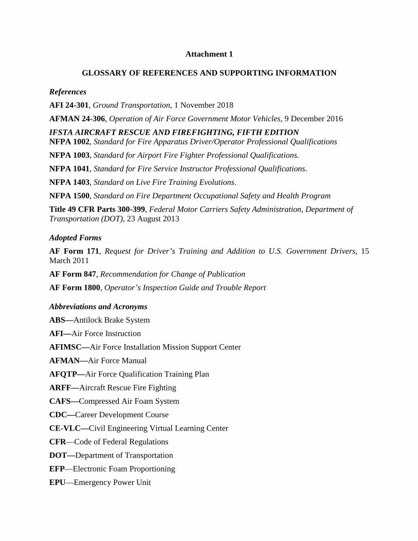
Attachment 1
GLOSSARY OF REFERENCES AND SUPPORTING INFORMATION
References AFI 24-301, Ground Transportation, 1 November 2018 AFMAN 24-306, Operation of Air Force Government Motor Vehicles, 9 December 2016
IFSTA AIRCRAFT RESCUE AND FIREFIGHTING, FIFTH EDITION NFPA 1002, Standard for Fire Apparatus Driver/Operator Professional Qualifications NFPA 1003, Standard for Airport Fire Fighter Professional Qualifications. NFPA 1041, Standard for Fire Service Instructor Professional Qualifications. NFPA 1403, Standard on Live Fire Training Evolutions. NFPA 1500, Standard on Fire Department Occupational Safety and Health Program Title 49 CFR Parts 300-399, Federal Motor Carriers Safety Administration, Department of Transportation (DOT), 23 August 2013 Adopted Forms AF Form 171, Request for Driver’s Training and Addition to U.S. Government Drivers, 15 March 2011 AF Form 847, Recommendation for Change of Publication AF Form 1800, Operator’s Inspection Guide and Trouble Report Abbreviations and Acronyms ABS—Antilock Brake System AFI—Air Force Instruction AFIMSC—Air Force Installation Mission Support Center AFMAN—Air Force Manual AFQTP—Air Force Qualification Training Plan ARFF—Aircraft Rescue Fire Fighting CAFS—Compressed Air Foam System CDC—Career Development Course CE-VLC—Civil Engineering Virtual Learning Center CFR—Code of Federal Regulations DOT—Department of Transportation EFP—Electronic Foam Proportioning EPU—Emergency Power Unit

FMCSA-- Federal Motor Carrier Safety Administration GPM—Gallons Per Minute HAZMAT—Hazardous Materials HRET--High Reach Extendable Turret IAW—In Accordance With IRT—Idle Reduction Technology IFSTA—International Fire Service Training Association NFPA—National Fire Protection Association OEM—Original Equipment Manufacturer ORM—Operational Risk Management PPS—Parts Per Second PSI─ Pounds per Square Inch RPM─ Revolutions per Minute TO—Technical Order USAF—United States Air Force VCNCO─ Vehicle Control Non Commissioned Officer VCO─ Vehicle Control Officer VIN—Vehicle Identification Number

Attachment 2
SUBJECT KNOWLEDGE
A2.1. P-23 Oshkosh 3000 Striker Vehicle Specifications. The following table gives specifications for the P-23 Oshkosh 3000 Striker. For additional information, refer to this vehicle’s Manufacturer’s Operator’s Manual. Table A2.1. P-23 Oshkosh 3000 Striker Vehicle Specifications.
Specifications P-23 Oshkosh 3000 Striker Part Specification
General Top Speed 70 MPH (112 km/hr) Gradability Ascend and Descend 50% Grade
Weight Loaded
83,720 lb 48,140 lb (Curb Weight) 35,580 lb (Payload, Max)
Overall Length 480’’ Overall Width 120’’ Overall Height 157’’ Reducible Height (Without HRET) 140’’ Wheel Base 267’’ Ground Clearance 15’’ (under axles) Angle of Approach/Departure 30 deg/30 deg Angle of Approach/Departure 21 deg./14 deg. Turning Radius 78’’
Booster Heater Make Eberspächer Heat Output 54,630 BTU/HR Primary Fuel Diesel Emergency Alternate Fuels JP-5 or JP-8 Fuel Consumption 0.48 gal/hr
Transmission Make Allison Model 4800 EVS Type 7-Speed Automatic Normal Operating Temperature 160ºF-200ºF Shifter Electronic Oil Capacity 16.6 gal (63 liters)
Cooling System Cooling System Capacity 15 gal (57 liters)

Fuel System Fuel Tank Capacity 90 Gallons (340.6 liters) Primary Fuel Diesel Emergency Alternate Fuels JP-5 or JP-8
Engine Make Deutz Type 16.0L V8 Model TCD Tier 4i Maximum Horsepower (At 2,100 rpm ) 697 hp Maximum Torque (At 1,400 rpm) 2131 ft/lb Oil Capacity 12.75 gal (48.3 liters) Engine Idle Speed 600 to 800 rpm Governed Speed 1950 rpm Normal Operating Temperature 160 degrees F Oil Pressure at Idle 150 psi
Nose Box (Transfer Case) Make Oshkosh
Type Independently Mounted with Torque Proportioning Differential and Driver Selected Locking Mechanism
Oil Capacity 1.5 gal (5.7 liters) Front Axle
Make Oshkosh Model Double-Reduction Differential Bevel Gear Oil Capacity 10.5 quarts
Rear Axle Make Oshkosh Model Double-Reduction Ratio Bevel Gear Oil Capacity/Type 13.0 and 10.5 quarts
Steering Type Hydraulic Power Pump Type Gear Driven Oil Capacity 5.5 gal (3.3 liter)
Brakes Service
Type Air/Drum/S-Cam Air Chamber Make Rockwell Make of Brake Parts Bendix
Parking Brake Type Spring Brake Modulating Make Bendix

Wheels Make Oshkosh Type 109A Size 21x18x3.75
Tires Type Tubeless 16 PR Size 24R21 XZL Air Pressure 95 psi (Cold)
Suspension
Type (Front and Rear) Oshkosh TAK-4 Independent Suspension System with Dual Control Arms
Shock Absorber Single Coil Springs Air System
Air Reservoirs 1 Primary, 2 Secondary
Air Reservoir Capacity 3200 cu in primary, 1228 and 2000 cu in secondary
Air Dryer Integrated Solution Air Dryer (ADIS) and Reservoir System
Side and Rear Air Coupling Type Automatic Air Line Disconnect Electrical System
Alternator Make DelcoRemy
Output 100 amp (24V) 160 – 180 – 200 (12V)
Lighting 24V Starting 24V
Batteries 4 12V in Series/Parallel depending if system is utilizing 12V or 24V
Circuit Protection Fuses and Circuit Breakers Power Divider
Make Oshkosh Type Oil cooled modulating clutch Oil Capacity 10 gal (37.9 liters)
Fire Fighting System Water Tank
Capacity 3,000 Gallons
Fill Connection (Standard) 2x 2 ½ in and 1x 4” Driver’s Side 1x 2 ½ in and 1x 4” Crew Chief Side
Construction UPF Poly Foam Tanks
Capacity 420 gal Fill Connection (Standard) One 1 ½ on Left Side Construction UPF Poly
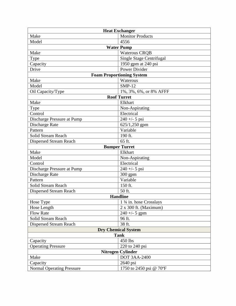
Heat Exchanger Make Monitor Products Model 4556
Water Pump Make Waterous CRQB Type Single Stage Centrifugal Capacity 1950 gpm at 240 psi Drive Power Divider
Foam Proportioning System Make Waterous Model SMP-12 Oil Capacity/Type 1%, 3%, 6%, or 8% AFFF
Roof Turret Make Elkhart Type Non-Aspirating Control Electrical Discharge Pressure at Pump 240 +/- 5 psi Discharge Rate 625/1,250 gpm Pattern Variable Solid Stream Reach 190 ft. Dispersed Stream Reach 65 ft.
Bumper Turret Make Elkhart Model Non-Aspirating Control Electrical Discharge Pressure at Pump 240 +/- 5 psi Discharge Rate 300 gpm Pattern Variable Solid Stream Reach 150 ft. Dispersed Stream Reach 50 ft.
Handline Hose Type 1 ¾ in. hose Crosslays Hose Length 2 x 300 ft. (Maximum) Flow Rate 240 +/- 5 gpm Solid Stream Reach 96 ft. Dispersed Stream Reach 38 ft.
Dry Chemical System Tank
Capacity 450 lbs Operating Pressure 220 to 240 psi
Nitrogen Cylinder Make DOT 3AA-2400 Capacity 2640 psi Normal Operating Pressure 1750 to 2450 psi @ 70ºF
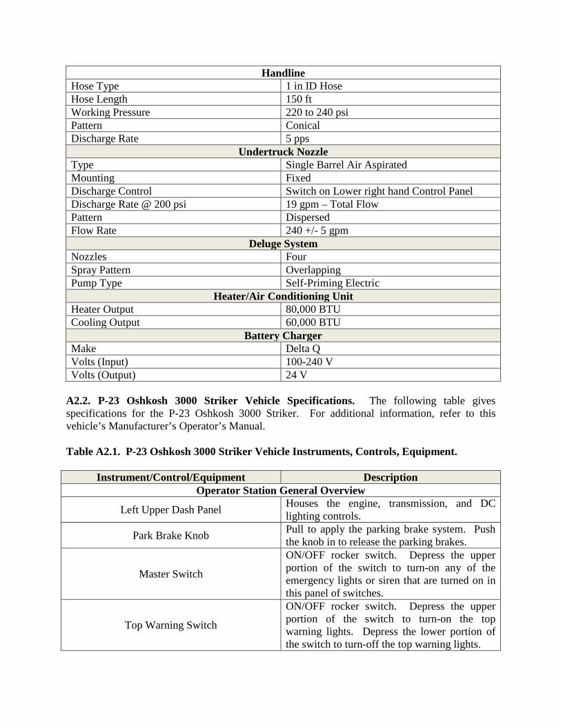
Handline Hose Type 1 in ID Hose Hose Length 150 ft Working Pressure 220 to 240 psi Pattern Conical Discharge Rate 5 pps
Undertruck Nozzle Type Single Barrel Air Aspirated Mounting Fixed Discharge Control Switch on Lower right hand Control Panel Discharge Rate @ 200 psi 19 gpm – Total Flow Pattern Dispersed Flow Rate 240 +/- 5 gpm
Deluge System Nozzles Four Spray Pattern Overlapping Pump Type Self-Priming Electric
Heater/Air Conditioning Unit Heater Output 80,000 BTU Cooling Output 60,000 BTU
Battery Charger Make Delta Q Volts (Input) 100-240 V Volts (Output) 24 V
A2.2. P-23 Oshkosh 3000 Striker Vehicle Specifications. The following table gives specifications for the P-23 Oshkosh 3000 Striker. For additional information, refer to this vehicle’s Manufacturer’s Operator’s Manual. Table A2.1. P-23 Oshkosh 3000 Striker Vehicle Instruments, Controls, Equipment.
Instrument/Control/Equipment Description Operator Station General Overview
Left Upper Dash Panel Houses the engine, transmission, and DC lighting controls.
Park Brake Knob Pull to apply the parking brake system. Push the knob in to release the parking brakes.
Master Switch
ON/OFF rocker switch. Depress the upper portion of the switch to turn-on any of the emergency lights or siren that are turned on in this panel of switches.
Top Warning Switch
ON/OFF rocker switch. Depress the upper portion of the switch to turn-on the top warning lights. Depress the lower portion of the switch to turn-off the top warning lights.

Perimeter Warning Switch
ON/OFF rocker switch. Depress the upper portion of the switch to turn-on the perimeter warning lights. Depress the lower portion of the switch to turn-off the perimeter warning lights.
Standby Switch
ON/OFF rocker switch. Depress the upper portion of the switch to turn-on the standby lights. Depress the lower portion of the switch to turn-off the standby lights.
Siren Switch
ON/OFF rocker switch. Depress the upper portion of the switch to activate the siren. Depress the bottom of the switch to deactivate the siren.
Shift Selector
The engine will only start when the shift selector is in the Neutral mode. Select Drive mode for normal driving. Completely stop the vehicle before shifting from any forward range to the Reverse range. Turn the vehicle high idle switch off before attempting to shift from Neutral to Drive or Reverse.
Dome Selection
Two-position rocker switch. Depress the upper portion of the switch to enable the dome lights to turn-on when the doors are opened. Depress the lower portion of the switch to disable the dome lights.
Door Light Lockout Switch
ON/OFF rocker switch. Depress the upper portion of the switch to enable the door lights to turn-on as the doors are opened. Depress the lower portion of the switch to disable the door lights.
Dash (Gauge) Lighting Switch
Press the top of the switch (+) to increase the dash (gauge) lighting intensity. Press the bottom of the switch (-) to decrease the dash (gauge) lighting intensity.
Fog Lights
Three position momentary rocker switch. Depress the upper portion of the switch to turn-on the vehicle’s fog lights. Depress the lower portion of the switch to turn-off the vehicle’s fog lights.
Drive Lights
Two-position rocker switch controls optional high-intensity drive lights located near headlights. Depress upper portion of switch to turn-on drive lights. Depress lower portion of switch to turn-off drive lights.
Heater Vents Allows the occupants to direct the flow of heated or cooled air.

Headlight Switch
A three-position (OFF, PARK, and DRIVE) rotary switch. The first switch (leftmost) position is the OFF position. The second switch position will activate the clearance/marker lights. The third switch position will activate the headlights.
Engine Kill Switch (Optional)
Emergency Engine Shutdown Switch. ON/OFF locking switch to be used in emergency situations only! Example: runaway engine. Depress the upper portion of the switch to shut down the engine. A spring loaded flapper on the engine air intake must be manually reset.
Hand Throttle Switch Momentary rocker switch. Press the top of the switch to increase engine speed. Press the bottom of the switch to decrease engine speed.
Engine Brake Switch
Engine Brake Switch. ON/OFF rocker switch. Depress the upper portion of the switch to turn the engine brake on. Depress the lower portion of the switch to turn the engine brake off.
Start Switch
A three-position (STOP, RUN, and START) rotary switch. The counterclockwise-most position is STOP. Rotating the switch one position clockwise provides power to the RUN position. The clockwise-most position is the momentary START position. When the switch is held in this position, the engine starter motor is engaged to crank the engine. The switch will return to the RUN position when released.
Steering Column. Houses the electric horn, windshield wiper, headlight high/low, and steering column tilt/telescoping controls.
Tilt/Telescoping Lever
Tilt. Pull and hold the lever toward the operator, and move the steering wheel to the desired position. Release the lever to lock the steering wheel in position. Telescope. Push and hold the lever away from the operator, and move the steering wheel in or out until the desired height is reached. Release the lever to lock the steering wheel in position.
Electric Horn Switch A momentary push button activates the electric horn.
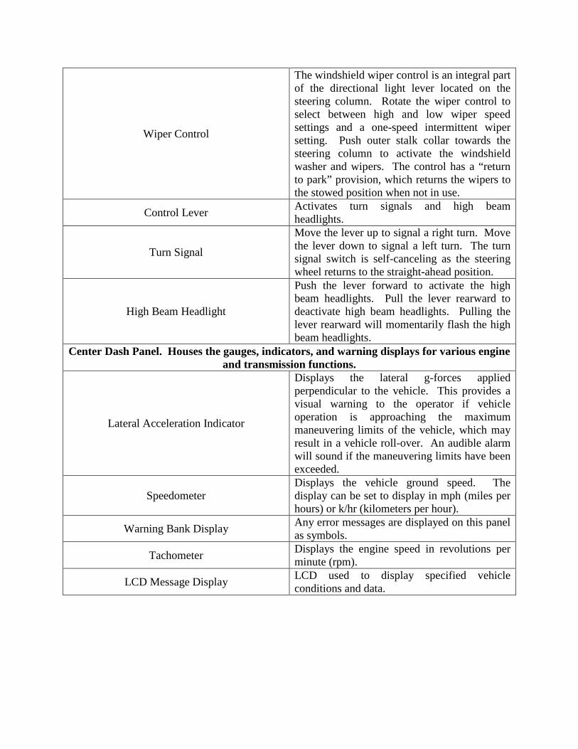
Wiper Control
The windshield wiper control is an integral part of the directional light lever located on the steering column. Rotate the wiper control to select between high and low wiper speed settings and a one-speed intermittent wiper setting. Push outer stalk collar towards the steering column to activate the windshield washer and wipers. The control has a “return to park” provision, which returns the wipers to the stowed position when not in use.
Control Lever Activates turn signals and high beam headlights.
Turn Signal
Move the lever up to signal a right turn. Move the lever down to signal a left turn. The turn signal switch is self-canceling as the steering wheel returns to the straight-ahead position.
High Beam Headlight
Push the lever forward to activate the high beam headlights. Pull the lever rearward to deactivate high beam headlights. Pulling the lever rearward will momentarily flash the high beam headlights.
Center Dash Panel. Houses the gauges, indicators, and warning displays for various engine and transmission functions.
Lateral Acceleration Indicator
Displays the lateral g-forces applied perpendicular to the vehicle. This provides a visual warning to the operator if vehicle operation is approaching the maximum maneuvering limits of the vehicle, which may result in a vehicle roll-over. An audible alarm will sound if the maneuvering limits have been exceeded.
Speedometer Displays the vehicle ground speed. The display can be set to display in mph (miles per hours) or k/hr (kilometers per hour).
Warning Bank Display Any error messages are displayed on this panel as symbols.
Tachometer Displays the engine speed in revolutions per minute (rpm).
LCD Message Display LCD used to display specified vehicle conditions and data.

Instrument Cluster
The instrument cluster includes the following gauges and warning lights: Battery Charge Level Gauge. Indicates the voltage output of the alternator. Low Battery Voltage Warning Light (Red). Illuminates for either a low or high voltage condition. Transmission Temperature Gauge. Indicates the transmission operating temperature. Transmission Temperature Warning Light (Red). Illuminates if the transmission temperature exceeds the recommended operating temperature. Rear Axle Brake System Air Pressure Gauge. Indicates the air pressure in the rear axle air system. Front Axle Brake System Air Pressure Gauge. Indicates the air pressure in the front axle air system. Brake System Low Air Pressure Warning Light (Red). Illuminates if the brake system air pressure drops below 73 psi.
“t” Trip/Reset Pushbutton 2 Used for display toggle and trip reset “m” Mode Pushbutton Used to display mode.
Instrument Cluster
The instrument cluster includes the following gauges and warning lights: Fuel Level Gauge. Indicates level of fuel in the fuel tank. Fill the tank at the end of each day’s operation to prevent condensation. Low Fuel Level Warning Light (Yellow). Indicates that the fuel level has dropped below 13%, and turns off when the level is above 18%. Diesel Exhaust Fluid (DEF) Level Gauge. Indicates the level of Diesel Exhaust Fluid (DEF). Low DEF Level Warning Light. Illuminated when the level of diesel exhaust fluid drops to 18%. The light will begin to flash when the level is above 18%. Engine Coolant Temperature Gauge. Indicates cooling system temperature. Refer to the engine manufacturer’s operation manual for specific engine operating requirements.

Engine Coolant Temperature Warning Light. Illuminates when the engine coolant exceeds the recommended operating temperature. Engine Oil Pressure Gauge. Displays the engine oil pressure while the engine is running. Excessive low oil pressure will activate the red STOP ENGINE warning light and a steady alarm tone. Low Engine Oil Pressure Warning Light. Warning light will illuminate when the engine oil pressure drops below the recommended operating pressure.
Inclinometer Displays the amount of side-to-side angle the vehicle is encountering.
Right Dash Panel. Houses and controls for various firefighting and external lighting functions.
Primary Display Panel
Secondary Display Panel (optional)
The display panel is used to display and control various camera systems such as: Forward Looking Infra-Red Camera (FLIR) Color Cameras Back-up Camera Snozzle® Camera Other Optional Systems
Heater Vents Allows the occupants to direct the flow of heated or cooled air.
Foam Switch
ON/OFF rocker switch. Depress the upper portion of the switch to activate the foam system. Depress the lower portion of the switch to deactivate the system.
Water Switch
ON/OFF rocker switch. Depress the upper portion of the switch to activate the water system. Depress the lower portion of the switch to deactivate the system.
Dry Chemical System Switch
ON/OFF rocker switch. Depress the upper portion of the switch to activate (charge) the dry chemical system. Depress the lower portion of the switch to deactivate the system.
Clean Agent Switch
ON/OFF rocker switch. Depress the upper portion of the switch to activate Haloton system. Depress the lower portion of the switch to deactivate the system.
Pump Engaged Indicator Light Illuminates when either the water or foam mode selector switch is in the ON position.

Generator Switch
Momentary two position rocker switch. Depress the upper portion of the switch to start the generator. Depress the lower portion of the switch to shut down generator. Generator provides power to operate right hand and left hand center body and cab mounted 220 V wide lights.
Front Wide Lights Switch
ON/OFF rocker switch. Depress the upper portion of the switch to turn-on the front wide lights. Depress the lower portion of the switch to turn-off the lights.
Left Wide Lights Switch
ON/OFF rocker switch. Depress the upper portion of the switch to turn-on the left wide lights. Depress the lower portion of the switch to turn-off the lights.
Right Wide Lights Switch
ON/OFF rocker switch. Depress the upper portion of the switch to turn-on the right wide lights. Depress the lower portion of the switch to turn-off the lights.
Rear Work Lights Switch
ON/OFF rocker switch. Depress the upper portion of the switch to turn-on the rear work lights. Depress the lower portion of the switch to turn-off the work lights.
Lights Raised Indicator Light When illuminated indicates that the wide lights are in the raised position.
Ground Lights Switch
ON/OFF rocker switch. Depress the upper portion of the switch to turn-on the grounds lights. Depress the lower portion of the switch to turn-off the ground lights.
Rear Work Lights Switch
ON/OFF rocker switch. Depress the upper portion of the switch to turn-on the rear work lights. Depress the lower portion of the switch to turn-off the work lights.
Right Work Lights Switch
ON/OFF rocker switch. Depress the upper portion of the switch to turn-on the right- hand work lights. Depress the lower portion of the switch to turn-off the work lights.
Left Work Lights Switch
ON/OFF rocker switch. Depress the upper portion of the switch to turn-on the left work lights. Depress the lower portion of the switch to turn-off the work lights.
Front HID Switch
ON/OFF rocker switch. Depress the upper portion of the switch to turn-on the high intensity discharge (HID) lights. Depress the lower portion of the switch to turn-off the lights.
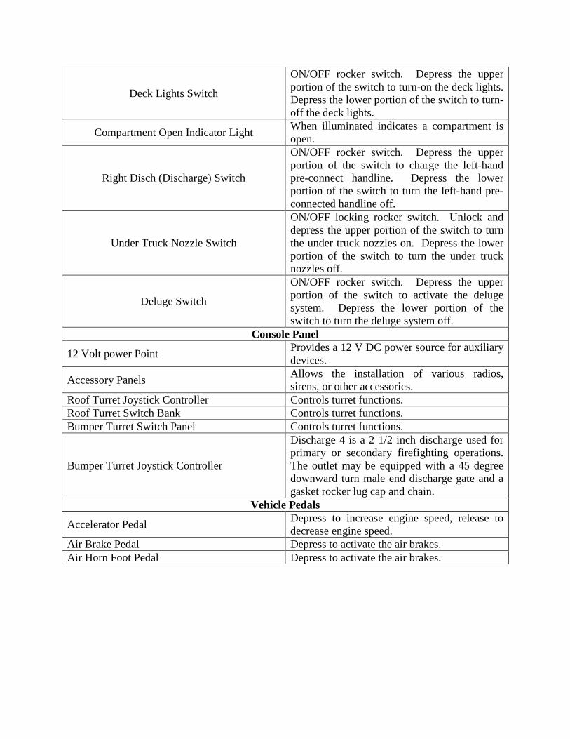
Deck Lights Switch
ON/OFF rocker switch. Depress the upper portion of the switch to turn-on the deck lights. Depress the lower portion of the switch to turn-off the deck lights.
Compartment Open Indicator Light When illuminated indicates a compartment is open.
Right Disch (Discharge) Switch
ON/OFF rocker switch. Depress the upper portion of the switch to charge the left-hand pre-connect handline. Depress the lower portion of the switch to turn the left-hand pre-connected handline off.
Under Truck Nozzle Switch
ON/OFF locking rocker switch. Unlock and depress the upper portion of the switch to turn the under truck nozzles on. Depress the lower portion of the switch to turn the under truck nozzles off.
Deluge Switch
ON/OFF rocker switch. Depress the upper portion of the switch to activate the deluge system. Depress the lower portion of the switch to turn the deluge system off.
Console Panel
12 Volt power Point Provides a 12 V DC power source for auxiliary devices.
Accessory Panels Allows the installation of various radios, sirens, or other accessories.
Roof Turret Joystick Controller Controls turret functions. Roof Turret Switch Bank Controls turret functions. Bumper Turret Switch Panel Controls turret functions.
Bumper Turret Joystick Controller
Discharge 4 is a 2 1/2 inch discharge used for primary or secondary firefighting operations. The outlet may be equipped with a 45 degree downward turn male end discharge gate and a gasket rocker lug cap and chain.
Vehicle Pedals
Accelerator Pedal Depress to increase engine speed, release to decrease engine speed.
Air Brake Pedal Depress to activate the air brakes. Air Horn Foot Pedal Depress to activate the air brakes.

Left Lower Dash Panel. Houses the heating/air conditioning and auxiliary equipment controls.
HVAC Control Panel
Blower (Fan Speed) Knob. The blower (fan speed) knob is a four-position rotary switch – Off, Low Speed, Medium Speed, and High Speed. From the OFF position (knob rotated fully counterclockwise), rotate the knob clockwise to the first stop to run the blower at low speed. Rotate the knob further clockwise to operate the blower at medium and high speeds Temperature Control Knob. Rotate the knob to select the desired temperature of the interior air. Adjust the temperature by positioning the temperature control along the blue/red scale. The coldest setting is in the blue and the warmest setting is in the red. Heater/Defroster Knob. With the knob in the HEAT position (knob rotated fully counterclockwise), all heated air will be diverted to the heating outlet ducts. As the knob is turned clockwise, some of the heated air is diverted to the defroster vents. When the knob is at the midpoint between the HEAT and DEF positions, the heated air will be equally split between the heater and defroster ducts. Continuing to turn the knob clockwise will divert more heated air to the defroster vents. A/C (Air Conditioning) Switch. ON/OFF pushbutton. Press to engage the air conditioning system. Press again to disengage the air conditioning system. Air Flow Control Switch. ON/OFF pushbutton. Press to recirculate the air.
Auxiliary Fan Switch (Optional)
ON/OFF rocker switch. Depress the upper portion of the switch to turn the cab auxiliary fans on. Depress the lower portion of the switch to turn the cab fans off. The toggle switch on the fans must be in either the HI or LOW position for the fans to operate.
Compt (Compartment) Heat
ON/OFF rocker switch. Depress the upper portion of the switch to turn the winterization heating system on. Depress the lower portion of the switch to turn the winterization heating system off.

Mirror Heat
ON/OFF rocker switch. Depress the upper portion of the switch to turn the mirror heaters on. Depress the lower portion of the switch to turn the mirror heaters off when the mirrors are clear.
Mirror Adjustment (Left)
Rotate the switch to select the upper or lower mirror to be adjusted. Move the switch to either the UP, DOWN, LEFT, or RIGHT direction to move the mirror in the corresponding direction.
Mirror Adjustment (Right)
Rotate the switch to select the upper or lower mirror to be adjusted. Move the switch to either the UP, DOWN, LEFT or RIGHT direction to move the mirror in the corresponding direction.
Driveline Selector Switch
A three-position (OPEN, TCASE, and DIFF) rotary switch. The counterclockwise position is the OPEN position (30% front, 70% rear). Rotating the switch one position clockwise is the TCASE position (50% front, 50% rear). The clockwise most position is the DIFF position. This position locks-up all axles from side-to-side.

Attachment 3
P-23 OSHKOSH 3000 STRIKER INSPECTION GUIDE
GENERAL STEP 1. VEHICLE OVERVIEW Paperwork
• AF Form 1800 • Discrepancy Correction Complete (VM Annotation)
Vehicle Approach • Damage • Vehicle Leaning? • Fresh Leakage of Fluids • Hazards Surrounding Vehicle
INTERNAL STEP 2. ENGINE COMPARTMENT Leaks/Hoses/Electrical Wiring Insulation Oil Level Coolant Level Power Steering Fluid Windshield Washer Fluid Battery Fluid Level, Connections & Tiedowns Automatic Transmission Fluid Level Engine Compartment Belts STEP 3. ENGINE START/CAB CHECK (LEFT/FRONT/RIGHT) Safe Start Gauges
• Oil Pressure Gauge • Air Pressure Gauge • Temperature Gauge (Coolant/Engine Oil) • Ammeter/Voltmeter
Siren Communications System Windows Seat Adjustment Mirrors & Windshield Wipers/Washers Removable Firefighting Equipment (missing/damaged) Emergency & Safety Equipment

• Spare Electrical Fuses • Red Reflective Triangles • 6 Fuses or 3 Liquid Burning Flares • Properly Charged & Rated Fire Extinguisher • Optional (Chains/Tire Changing Equip, Emergency Phone List)
3B – Lights/Reflectors/Reflector Tape Condition (Front/Sides/Rear) (Dash Indicators for:)
• Left Turn Signal • Right Turn Signal • Four-Way Emergency Flashers • High Beam Headlight • ABS Indicator • Clearance Lights
(Reflective Clean & Functional Light & Reflector Checks Include:) • Headlights • Taillights • Backing Lights • Turn Signals • Four-Way Flashers • Brake Lights • Red Reflectors & Amber Reflectors • Reflective Tape Condition
Horn Heater/Defroster Brakes
• Parking Brake Check • Hydraulic Brake Check • Air Brake Check • Service Brake Check • Safety Belt
(TURN-OFF ENGINE/TURN-ON HEADLIGHTS *LOW BEAM* AND FOUR-WAY FLASHERS) STEP 4. WALK-AROUND INSPECTION 4A – Steering
• Steering Box/Hoses • Steering Linkages
4B – Suspension • Springs/Air/Torque • Mounts • Shock Absorbers
4C – Brakes • Slack Adjustors & Pushrods

• Brake Chambers • Brake Hoses/Lines • Drum Brake • Brake Linings
4D – Wheels • Rims • Tires • Hub Oil Seals/Axle Seals • Lug Nuts • Spacers & Budd Spacing
4D – Body Panels
LEFT SIDE/DRIVER SIDE OF P-23 OSHKOSH 3000 STRIKER 4E – Doors 4E – Mirrors 4E – Fuel Tank
RIGHTSIDE/PASSENGER SIDE OF P-23 OSHKOSH 3000 STRIKER 4E – Doors 4E – Mirrors 4E – Fuel Tank 4E – Body Panels UNDER VEHICLE 4F – Drive Shaft 4F – Exhaust 4F – Frame FIREFIGHTING EQUIPMENT, WATER & FOAM PIPING 4G – Piping/Drain Valves (Underside) 4G – Foam Tank Gate Valve 4G – Foam Tank Overflow Hose Clamp 4G – Firefighting Equipment 4G – Dispense Systems Gauge Readings 4G – Hose Reel 4G – Hose REAR OF P-23 OSHKOSH 3000 STRIKER 4H – Doors

Figure A3.1. P-23 Oshkosh 3000 Striker Inspection Guide.

Attachment 4
PERFORMANCE TEST
A4.1. Desired Learning Outcome.
A4.1.1. Understand the safety precautions to be followed before-, during-, and after-operation of the P-23 Oshkosh 3000 Striker. A4.1.2. Understand the purpose of the P-23 Oshkosh 3000 Striker and its role in the mission. A4.1.3. Know the proper operator maintenance procedures of the P-23 Oshkosh 3000 Striker IAW applicable technical orders and use of AF Form 1800. A4.1.4. Safely and proficiently operate the P-23 Oshkosh 3000 Striker.
A4.2. Instructions. Before the trainee begins the performance test, the trainer will brief the trainee on the scenario he/she will need to accomplish. The trainee will be given additional directions and instructions as needed as he/she proceeds through the scenario. A4.3. Scoring.
A4.3.1. The trainer examiner will be scoring the trainee on P-23 Oshkosh 3000 Striker operations and also the general safe driving practices. The examiner will give directions and instructions to the trainee in sufficient time for the trainee to execute a driving maneuver. The trainee will not be asked to drive in an unsafe manner. A4.3.2. The examiner will be making various marks on the performance test checklist. This does not necessarily mean the trainee has done anything wrong. It is in the best interest to concentrate on the operation of the P-23 Oshkosh 3000 Striker. The trainer will explain the test results to the trainee at the conclusion of the performance test. A4.3.3. Tasks being graded are listed on the following page; the trainee will be required to successfully pass all items. A4.3.4. The instructor will stop the test at any time safe P-23 Oshkosh 3000 Striker operations are not being followed or as deemed necessary for safety concerns.
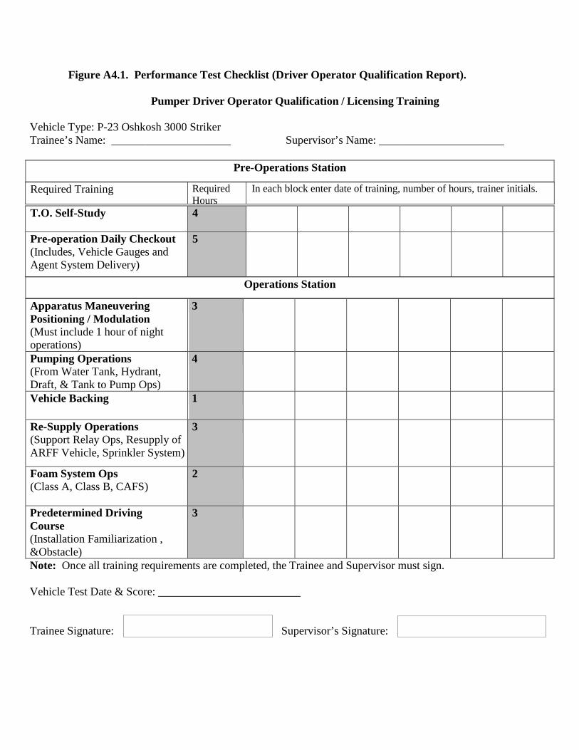
Figure A4.1. Performance Test Checklist (Driver Operator Qualification Report). Pumper Driver Operator Qualification / Licensing Training
Vehicle Type: P-23 Oshkosh 3000 Striker Trainee’s Name: _____________________ Supervisor’s Name: ______________________
Apparatus Maneuvering Positioning / Modulation (Must include 1 hour of night operations)
3
Pumping Operations (From Water Tank, Hydrant, Draft, & Tank to Pump Ops)
4
Vehicle Backing
1
Re-Supply Operations (Support Relay Ops, Resupply of ARFF Vehicle, Sprinkler System)
3
Foam System Ops (Class A, Class B, CAFS)
2
Predetermined Driving Course (Installation Familiarization , &Obstacle)
3
Note: Once all training requirements are completed, the Trainee and Supervisor must sign.
Vehicle Test Date & Score: _________________________
Trainee Signature: Supervisor’s Signature:
T.O. Self-Study 4
Pre-operation Daily Checkout (Includes, Vehicle Gauges and Agent System Delivery)
5
Pre-Operations Station
Required Training Required Hours
In each block enter date of training, number of hours, trainer initials.
Operations Station

Trainee’s Name: ___________________ Evaluators Name: _________________________
Driver Operator Certification Report Candidate must pass all evaluated areas for licensing
Note: Refer to CDC 10023W Driver/Operator - Pumper Performance Test for detailed description of above task
Driver Operator Remedial Training
If a candidate fails a certification task, provide an explanation of what remedial training was accomplished to correct deficiency.
Date Trainer Trainee Initials
Task(s) Failed
What training was done to correct the deficiency:
I certify that I have tested the above individual and they are proficient to drive and operate the vehicle. Evaluator Signature:
Go No-Go Evaluated Area Successfully complete all pre-operations daily checks
(Inside Cab, Outside, Engine Compartment, Fire Pump, Water Tank, Foam Tank/System, Tools and Equipment )
Successfully pump from water tank, hydrant and draft Successfully produce a master stream Successfully support a supply line in a relay operation Successfully pump a supply line to an ARFF apparatus Successfully produce a foam fire stream Successfully support a sprinkler and standpipe system Successfully demonstrate knowledge for all 6 annual pump service tests
(Vacuum, Priming, Control, Gauge, and Flow Meter, Tank to Pump Flow, Pumping Tests) Successfully drive the vehicle on a predetermined public roadway
(4 Left Turns, 4 Right Turns, Straight Section of Road, Passing through 1 Intersection, Passing through 2 Intersections with a Stop, Curve in Roadway, Change Lanes, Enter/Exit Limited Access, Downgrade/Upgrade, Underpass/Low Clearance )
Successfully complete an obstacle driving course (Alley Dock, Serpentine, 180 degree Turnaround, Diminished Clearance, Lane Change, Straight Line )
Successfully demonstrated a working knowledge of fire ground hydraulics
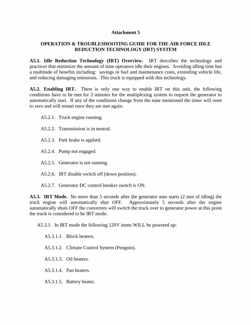
Attachment 5
OPERATION & TROUBLESHOOTING GUIDE FOR THE AIR FORCE IDLE REDUCTION TECHNOLOGY (IRT) SYSTEM
A5.1. Idle Reduction Technology (IRT) Overview. IRT describes the technology and practices that minimize the amount of time operators idle their engines. Avoiding idling time has a multitude of benefits including: savings in fuel and maintenance costs, extending vehicle life, and reducing damaging emissions. This truck is equipped with this technology. A5.2. Enabling IRT. There is only one way to enable IRT on this unit, the following conditions have to be met for 2 minutes for the multiplexing system to request the generator to automatically start. If any of the conditions change from the state mentioned the timer will reset to zero and will restart once they are met again:
A5.2.1. Truck engine running. A5.2.2. Transmission is in neutral. A5.2.3. Park brake is applied. A5.2.4. Pump not engaged. A5.2.5. Generator is not running. A5.2.6. IRT disable switch off (down position). A5.2.7. Generator DC control breaker switch is ON.
A5.3. IRT Mode. No more than 5 seconds after the generator auto starts (2 min of idling) the truck engine will automatically shut OFF. Approximately 5 seconds after the engine automatically shuts OFF the converters will switch the truck over to generator power at this point the truck is considered to be IRT mode.
A5.3.1. In IRT mode the following 120V items WILL be powered up:
A5.3.1.1. Block heaters.
A5.3.1.2. Climate Control System (Penguin).
A5.3.1.3. Oil heaters.
A5.3.1.4. Pan heaters.
A5.3.1.5. Battery heater.

A5.3.1.6. Battery chargers.
A5.3.1.7. IRT converters.
A5.3.2. In IRT mode the following 12V items WILL be powered:
A5.3.2.1. Radios. A5.3.2.2. DOT lighting. A5.3.2.3. NFPA required emergency lights. A5.3.2.4. Step lights. A5.3.2.5. Work lights. A5.3.2.6. Compartment lights.
A5.3.3. In IRT mode the following 120V items will NOT be powered:
A5.3.3.1. Lights. A5.3.3.2. Reels. A5.3.3.3. Receptacles.
A5.3.4. The truck is considered to be in Generator mode when converters are not enabled and the generator was manually started with the truck running this mode the gen will need to have manual preheat applied via the switch in the overhead driver side before the gen is started. Gen mode the following 120V items WILL be powered:
A5.3.4.1. Reel. A5.3.4.2. Receptacles.
A5.3.5. To switch from IRT mode to normal operation mode:
A5.3.5.1. Bring Ignition switch one click down to Master power. A5.3.5.2. Wait for generator to turn-off. A5.3.5.3. Wait 2 seconds. A5.3.5.4. Power back up and start truck.

A5.4. IRT Operating Indicator. Light found in overhead driver side.
A5.4.1. The IRT operating indicator will flash 120 fpm when disable switch is in “ON” position indicating IRT CANNOT be enabled. Not flashing if service switch is OFF, steady burn indicates IRT is operating a custom flash pattern when the DC control breaker found on the generator is in the OFF position. A5.4.2. If the generator cranks but does not run within approx. 10 sec of the request to start, cycle power to truck and with engine not running verify generator functionality manually via the manual start button in the overhead or with the switch found on the generator itself. A5.4.3. If generator is running but does not switch over, verify converter breakers and solenoids are working properly, converters not switching over will sound the reverse alarm.
Figure A5.1. Troubleshooting IRT Problems.
Troubleshooting IRT Problems Symptom Possible Solution
Generator does not automatically start after 2 minutes of truck idle.
Verify that: Truck engine is running; Transmission is in neutral; Park Brake is applied; Pump not engaged; Generator is not running; IRT disable switch is off (down position); Switch on generator is in the ON position.
Manually change state to each command mentioned above. Cycle Power to truck. Contact local dealer for support.
Generator running but converters do not power up.
Verify that the generator started automatically after truck has been idling for 2 min. Verify that the coil side of relay has 12 volts to ground. If not, contact local dealer for support. Verify source side of relay has 120 volts to ground. If not, press fault reset button on generator. Verify load side of relay has 120 volts to ground. If not, replace relay.
Generator running and convertors are ON, does not switch from battery power to generator power.
Verify source side of solenoid has 12 volts to ground. If not, verify fuse, replace if necessary. Verify load side of solenoid has 12 volts to ground. If, not replace solenoid. Verify trigger wire to solenoid has 12 volts to ground. If not, verify connection of wire.

Truck 12 volt A/C not working when IRT turned off.
Turn truck OFF for 2 seconds. Contact local dealer for support.
Reverse warning when generator auto start and engine auto OFF.
Converters did not power up or solenoids did not transfer truck to generator power. Cycle power to truck.
Verify symptom "Generator running but converters do not power up" Verify load side of fuse has 12 volts to ground. If not, replace fuse. Contact local dealer for support.

Attachment 6
SEVEN-STEP INSPECTION PROCESS Figure A6.1. Seven-Step Inspection Process.
Seven-Step Inspection Process Step Procedure 1. Vehicle Overview • Review the AF Form 1800.
o Ensure any discrepancy has been corrected.
o Vehicle Management annotated the discrepancy was completed.
o Approaching the vehicle. Damage or vehicle leaning to one
side. Fresh leakage of fluids. Hazards around vehicle.
2. Check Engine Compartment • Note: Check that the parking brakes are on and/or wheels chocked. The operator may have to raise the hood, tilt the cab (secure loose things so they don't fall and break something), or open the engine compartment door.
• Check the following: o Engine oil level. o Coolant level in radiator; condition of
hoses. o Power steering fluid level; hose
condition (if so equipped). o Windshield washer fluid level. o Battery fluid level, connections and
tie-downs (battery may be located elsewhere).
o Automatic transmission fluid level (may require engine to be running).

o Check belts for tightness and excessive wear (alternator, water pump, air compressor)--learn how much "give" the belts should have when adjusted right.
o Leaks in the engine compartment (fuel, coolant, oil, power steering fluid, hydraulic fluid, battery fluid). Cracked, worn electrical wiring insulation.
3. Start Engine and Inspect Inside the Cab Get in and Start Engine
• Make sure parking brake is on. • Put gearshift in neutral (or park if
automatic). Start engine; listen for unusual noises.
• If equipped, check the Anti-lock Braking System (ABS) indicator lights. Light on dash should come on and then turn-off. If it stays on the ABS is not working properly.
• Note: For trailers only, if the yellow light on the left rear of the trailer stays on, the ABS is not working properly.
• Look at the gauges. o Oil pressure. Should come up to
normal within seconds after engine is started.
o Air pressure. Pressure should build from 50 to 90 psi within 3 minutes. Build air pressure to governor cut-out (usually around 120 – 140 psi. Know the vehicle’s requirements.
o Ammeter and/or voltmeter. Should be in normal range(s).
o Coolant temperature. Should begin gradual rise to normal operating range.
o Engine oil temperature. Should begin gradual rise to normal operating range.

o Warning lights and buzzers. Oil, coolant, charging circuit warning, and antilock brake system lights should go out right away.
o Check Condition of Controls. Check all of the following for looseness, sticking, damage, or improper setting:
Steering wheel. Clutch. Accelerator (gas pedal). Brake controls. Foot brake. Trailer brake (if vehicle has one). Parking brake. Retarder controls (if vehicle has
them). Transmission controls. Interaxle differential lock (if vehicle
has one). Horn(s). Windshield wiper/washer. Lights. Headlights. Dimmer switch. Turn signal. Four-way flashers. Parking – clearance – identification –
marker switch (switches). • Check mirrors and windshield. o Inspect mirrors and windshield for
cracks, dirt, illegal stickers, or other obstructions to seeing clearly. Clean and adjust as necessary.
• Check emergency equipment. o Check for safety equipment: Spare electrical fuses (unless vehicle
has circuit breakers). Three red reflective triangles, 6 fuses
or 3 liquid burning flares.

Properly charged and rated fire extinguisher. Check for optional items such as:
Chains (where winter conditions require).
Tire changing equipment. List of emergency phone numbers
Accident reporting kit (packet). o Check safety belt. Check that the
safety belt is securely mounted, adjusts; latches properly and is not ripped or frayed.
4. Turn-off Engine • Make sure the parking brake is set, turn-off the engine, and take the key with.
• Turn-on headlights (low beams) and four-way emergency flashers, and get out of the vehicle.
5. Do Walk-Around Inspection • General. o Go to front of vehicle and check that
low beams are on and both of the four-way flashers are working.
o Push dimmer switch and check that high beams work.
o Turn-off headlights and four-way emergency flashers.
o Turn-on parking, clearance, side-marker, and identification lights.
o Turn-on right turn signal, and start walk-around inspection.
o Walk around and inspect. Clean all lights, reflectors, and glass
as while doing the walk-around inspection.
• Left front side. o Driver's door glass should be clean. o Door latches or locks should work
properly. • Left front wheel.

o Condition of wheel and rim--missing, bent, broken studs, clamps, lugs, or any signs of misalignment.
o Condition of tires--properly inflated, valve stem and cap OK, no serious cuts, bulges, or tread wear.
o Use wrench to test rust-streaked lug nuts, indicating looseness.
o Hub oil level OK, no leaks. Left front suspension.
o Condition of spring, spring hangers, shackles,
o U-bolts. o Shock absorber condition. • Left front brake. o Condition of brake drum or disc. o Condition of hoses. • Front. o Condition of front axle. Condition of
steering system. o No loose, worn, bent, damaged or
missing parts. o Must grab steering mechanism to test
for looseness. o Condition of windshield. o Check for damage and clean if dirty. o Check windshield wiper arms for
proper spring tension. o Check wiper blades for damage,
"stiff" rubber, and securement. o Lights and reflectors. o Parking, clearance, and identification
lights clean, operating, and proper color (amber at front).
o Reflectors clean and proper color (amber at front).
o Right front turn signal light clean, operating, and proper color (amber or white on signals facing forward).
• Right side

o Right front: check all items as done on left front.
o Primary and secondary safety cab locks engaged (if cab-over-engine design).
o Right fuel tank(s). o Securely mounted, not damaged, or
leaking. Fuel crossover line secure. o Tank(s) contain enough fuel. Cap(s)
on and secure. o Condition of visible parts. Rear of
engine--not leaking. Transmission--not leaking.
o Exhaust system--secure, not leaking, not touching wires, fuel, or air-lines.
o Frame and cross members--no bends or cracks.
o Air-lines and electrical wiring--secured against snagging, rubbing, wearing.
o Spare tire carrier or rack not damaged (if so equipped).
o Spare tire and/or wheel securely mounted in rack.
o Spare tire and wheel adequate (proper size, properly inflated).
o Cargo securement (trucks). o Cargo properly blocked, braced, tied,
chained, etc. Header board adequate, secure (if required).
o Side boards, stakes strong enough, free of damage, properly set in place (if so equipped).
o Canvas or tarp (if required) properly secured to prevent tearing, billowing, or blocking of mirrors.
o If oversize, all required signs (flags, lamps, and reflectors) safely and properly mounted and all required permits in driver's possession.

o Curbside cargo compartment doors in good condition, securely closed, latched/locked and required security seals in place.
• Right rear. o Condition of wheels and rims--no
missing, bent, or broken spacers, studs, clamps, or lugs.
o Condition of tires--properly inflated, valve stems and caps OK, no serious cuts, bulges, tread wear, tires not rubbing each other, and nothing stuck between them.
o Tires same type, e.g., not mixed radial and bias types.
o Tires evenly matched (same sizes). Wheel bearing/seals not leaking.
o Suspension. o Condition of spring(s), spring
hangers, shackles, and u-bolts. o Axle secure. o Powered axle(s) not leaking lube
(gear oil). Condition of torque rod arms, bushings.
o Condition of shock absorber(s). o If retractable axle equipped, check
condition of lift mechanism. If air powered, check for leaks.
o Condition of air ride components. o Brakes. o Brake adjustment. o Condition of brake drum(s) or discs. o Condition of hoses--look for any
wear due to rubbing. o Lights and reflectors. o Side-marker lights clean, operating,
and proper color (red at rear, others amber).
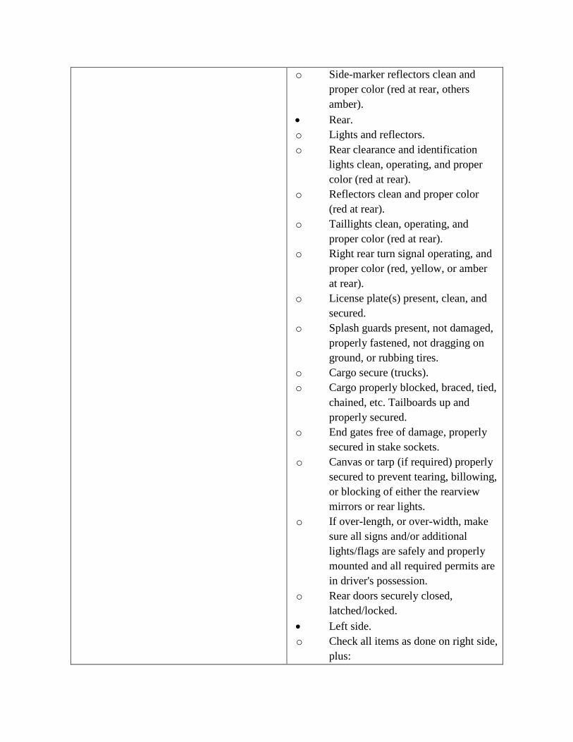
o Side-marker reflectors clean and proper color (red at rear, others amber).
• Rear. o Lights and reflectors. o Rear clearance and identification
lights clean, operating, and proper color (red at rear).
o Reflectors clean and proper color (red at rear).
o Taillights clean, operating, and proper color (red at rear).
o Right rear turn signal operating, and proper color (red, yellow, or amber at rear).
o License plate(s) present, clean, and secured.
o Splash guards present, not damaged, properly fastened, not dragging on ground, or rubbing tires.
o Cargo secure (trucks). o Cargo properly blocked, braced, tied,
chained, etc. Tailboards up and properly secured.
o End gates free of damage, properly secured in stake sockets.
o Canvas or tarp (if required) properly secured to prevent tearing, billowing, or blocking of either the rearview mirrors or rear lights.
o If over-length, or over-width, make sure all signs and/or additional lights/flags are safely and properly mounted and all required permits are in driver's possession.
o Rear doors securely closed, latched/locked.
• Left side. o Check all items as done on right side,
plus:

o Battery (batteries) (if not mounted in engine compartment).
o Battery box (boxes) securely mounted to vehicle. Box has secure cover.
o Battery (batteries) secured against movement. Battery (batteries) not broken or leaking.
o Fluid in battery (batteries) at proper level (except maintenance-free type).
o Cell caps present and securely tightened (except maintenance-free type).
o Vents in cell caps free of foreign material (except maintenance-free type).
6. Check Signal Lights • Get in and turn-off all lights. • Turn-on stop lights (apply trailer
hand brake or have a helper put on the brake pedal).
• Turn-on left turn signal lights. • Get out and check lights. • Left front turn signal light clean,
operating and proper color (amber or white on signals facing the front).
• Left rear turn signal light and both stop lights clean operating, and proper color (red, yellow, or amber).
• Get in vehicle. o Turn-off lights not needed for
driving. o Check for all required papers, trip
manifests, permits, etc. o Secure all loose articles in cab (they
might interfere with operation of the controls or hit the operator in a crash).
o Start the engine.

7. Start the Engine and Check Test for Hydraulic Leaks
• Test for hydraulic leaks. o If the vehicle has hydraulic brakes,
pump the brake pedal three times. o Then apply firm pressure to the pedal
and hold for five seconds. o The pedal should not move. If it
does, there may be a leak or other problem.
• Brake system. • Test parking brake. o Fasten safety belt. o Set parking brake (power unit only).
Release trailer parking brake (if applicable). Place vehicle into a low gear.
o Gently pull forward against parking brake to make sure the parking brake holds.
o Repeat the same steps for the trailer with trailer parking brake set and power unit parking brakes released (if applicable).
o If it doesn't hold vehicle, it is faulty; get it fixed.
• Test service brake stopping action. o Go about 5 miles per hour. o Push brake pedal firmly. o "Pulling" to one side or the other can
mean brake trouble. o Any unusual brake pedal "feel" or
delayed stopping action can mean trouble.
o If the trainee finds anything unsafe during the Vehicle inspection, get it fixed. Federal and state laws forbid operating an unsafe vehicle.
• Check vehicle operation regularly: o Instruments.
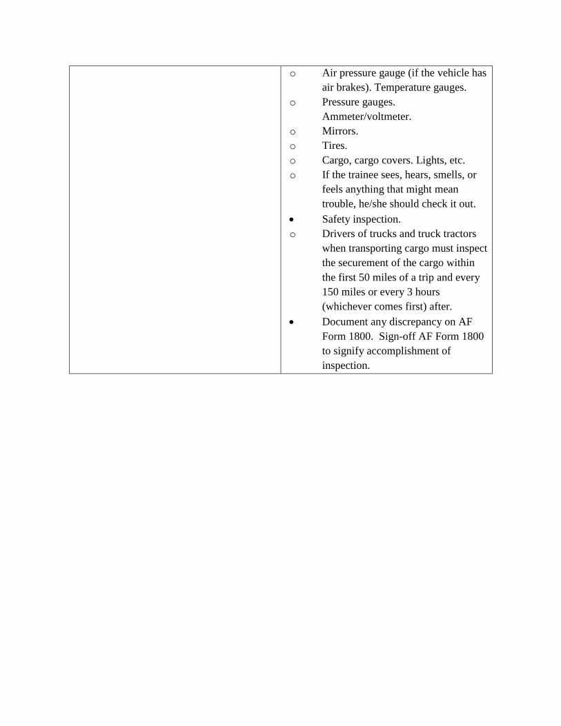
o Air pressure gauge (if the vehicle has air brakes). Temperature gauges.
o Pressure gauges. Ammeter/voltmeter.
o Mirrors. o Tires. o Cargo, cargo covers. Lights, etc. o If the trainee sees, hears, smells, or
feels anything that might mean trouble, he/she should check it out.
• Safety inspection. o Drivers of trucks and truck tractors
when transporting cargo must inspect the securement of the cargo within the first 50 miles of a trip and every 150 miles or every 3 hours (whichever comes first) after.
• Document any discrepancy on AF Form 1800. Sign-off AF Form 1800 to signify accomplishment of inspection.
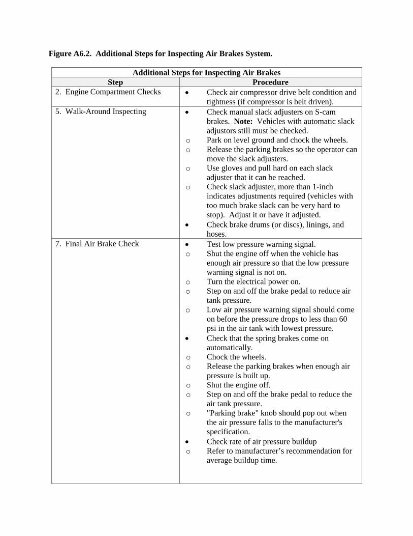
Figure A6.2. Additional Steps for Inspecting Air Brakes System.
Additional Steps for Inspecting Air Brakes Step Procedure
2. Engine Compartment Checks • Check air compressor drive belt condition and tightness (if compressor is belt driven).
5. Walk-Around Inspecting • Check manual slack adjusters on S-cam brakes. Note: Vehicles with automatic slack adjustors still must be checked.
o Park on level ground and chock the wheels. o Release the parking brakes so the operator can
move the slack adjusters. o Use gloves and pull hard on each slack
adjuster that it can be reached. o Check slack adjuster, more than 1-inch
indicates adjustments required (vehicles with too much brake slack can be very hard to stop). Adjust it or have it adjusted.
• Check brake drums (or discs), linings, and hoses.
7. Final Air Brake Check • Test low pressure warning signal. o Shut the engine off when the vehicle has
enough air pressure so that the low pressure warning signal is not on.
o Turn the electrical power on. o Step on and off the brake pedal to reduce air
tank pressure. o Low air pressure warning signal should come
on before the pressure drops to less than 60 psi in the air tank with lowest pressure.
• Check that the spring brakes come on automatically.
o Chock the wheels. o Release the parking brakes when enough air
pressure is built up. o Shut the engine off. o Step on and off the brake pedal to reduce the
air tank pressure. o "Parking brake" knob should pop out when
the air pressure falls to the manufacturer's specification.
• Check rate of air pressure buildup o Refer to manufacturer’s recommendation for
average buildup time.

o If not within recommended time, the air pressure may drop too low during driving operations.
• Test air leakage rate. o With a fully-charged air system (typically 125
psi). o Turn-off the engine. o Release the service brake and time the air
pressure drop. o The loss rate should be less than 2 psi in one
minute for single vehicles. o Not less than 3 psi in 1 minute for
combination vehicles. • Then apply 90 psi or more with the brake
pedal. o After the initial pressure drop, if the air
pressure falls more than 3 psi in 1 minute for single vehicles.
o Not more than 4 psi for combination vehicles. • Check air compressor governor cut-in and cut-
out pressures. o Air compressor should start at about 100 psi
and stop at about 125 psi. o Run the engine at a fast idle. o Air governor should cut-out the air
compressor at about the manufacturer's specified pressure.
o Engine idling, step on and off brake to reduce air tank pressure.
o Compressor should cut-in at manufacturer's specified cut-in pressure.
o Test parking brake: Stop the vehicle; put the parking brake on; gently pull against it in low gear to determine if parking brake will hold.
Test service brakes. Wait for normal air pressure. • Release the parking brake. • Move the vehicle forward slowly (about 5
mph). • Apply the brakes firmly using the brake pedal. • Note any vehicle "pulling" to one side,
unusual feel, or delayed stopping action.