department of the army technical manual tm 5 … · department of the army technical manual tm...
TRANSCRIPT
DEPARTMENT OF THE ARMY TECHNICAL MANUAL TM 5-6675-231-15
DEPARTMENT OF THE AIR FORCE TECHNICAL ORDER TO 49A8-10-1
OPERATOR, ORGANIZATIONAL, FIELD,
AND DEPOT MAINTENANCE MANUAL
THEODOLITE; DIRECTIONAL
2/10 SEC, DEGREE GRADUATION
10.2-IN. LONG TELESCOPE
W / ACCESSORIES
(WILD HEERBRUGG MODEL T-3)
FSN 6675-382-9140
This copy is a reprint which includescurrent pages from Change 4.
D E P A R T M E N T S O F T H E A R M Y A N D T H E A I R F O R C E
J U N E 1 9 6 3
AGO 5078A

Changes in force: C4 TM 5-6675-231-15TO 49A8-10-1
*C4Change DEPARTMENTS OF THE ARMY
AND THE AIR FORCENo. 4 WASHINGTON, D.C., 15 August 1978
Operator, Organizational, Field and Depot Maintenance ManualTHEODOLITE, SURVEYING, DIRECTIONAL, 2/10 SEC.
DEGREE GRADUATION; 10.2 INCH LONG TELESCOPE W / ACCESSORIES(WILD HEERBRUGG MODEL T-3) NSN 6675-00-382-9140
(WILD HEERBRUGG MODEL T3-1969) NSN 6675-00-411-5446
TM 5-6675-231-15/TO 49A8-10-1, 28 June 1963 ischanges as follows:
Cover and table of contents page are changed as shownabove.
Page 1. Immediately after title add the following:
Reporting Errors and Recommending Improvements
You can help improve this manual. If you find anymistake or if you know of a way to improve theprocedures, please let us know. Mail your letter, DAForm 2028 (Recommended Changes to Publicationsand Blank Forms), or DA Form 2028-2 located in theback of this manual direct to Commander, US ArmyTroop Support and Aviation Materiel ReadinessCommand, ATTN: DRSTSMTPS, 4300 GoodfellowBlvd., St. Louis, Missouri 63120. A reply will befurnished directly to you.
Page 2. The appendices are changed as follows:Appendix I. ReferenceAppendix II. Component of End Item ListAppendix III. Additional Authorization ListAppendix IV. Maintenance Allocation ChartAppendix V. Expendable Supplies and Materials List
Page 3. Paragraph 1b is superseded as follows:
b. Appendix I contains a list of publicationsapplicable to this manual. Appendix II contains a list ofcomponents of end item. Appendix III contains theadditional authorization list. Appendix IV contains themaintenance allocation chart. Appendix V contains theexpendable supplies and materials list. Theorganizational, field, and depot maintenance repair partsand special tools list are listed in TM 5-6675-231-25P.
Paragraph 1d is deleted in its entirety.
Paragraph 1e is changed to read paragraph 1d.
Page 92. Change "Appendix II, MaintenanceAllocation Chart" to read "Appendix IV, MaintenanceAllocation Chart" and add after Appendix III.
Appendix II. After Appendix I add "Appendix II,Components of End Item List".
*This change supersedes C3, 25 June 1973
1
}
1
TM 5-6675-231-15TO 49A8-10-1
C4
APPENDIX IICOMPONENTS OF END ITEMS LIST
Section I. INTRODUCTION
1. ScopeThis appendix lists Intergral Components of and BasicIssue Items (BII) for the Directional Theodolite to helpyou inventory items required for safe and efficientoperation.
2. GeneralThe components of end item list are divided into the
following sections:a. Section II. Integral Components of the End
Item. These items, when assembled, comprise theDirectional Theodolite and must accompany it wheneverit is transferred or turned in. These illustrations will helpyou identify these items.
b. Section III. Basic Issue Items. These areminimum essential items required to place theDirectional Theodolite in operation, to operate it and toperform emergency repairs. Although shippedseparately packed, they must accompany theDirectional Theodolite during operation and whenever itis transferred between accountable officers. Theillustrations will assist you with hard-to-identify items.This manual is your authority to requisition replacementBII based on Table(s) of Organization and Equipment(TOE)/Modification Table of Organization andEquipment (MTOE) authorization of the end item.
3. Explanation of Columnsa. Illustration. This column is divided as follows.
(1) Figure Number. Indicates the figurenumber of the illustration on which theitem is shown (if applicable).
(2) Item Number. The number used toidentify item called out in the illustration.
b. National Stock Number (NSN). Indicates thenational stock number assigned to the end item whichwill be used for requisitioning.
c. Part Number (P/N). Indicates the primarynumber used by the manufacturer which controls thedesign and characteristics of the item by means of itsengineering drawings, specifications, standards andinspection requirements to identify an item or range ofitems.
d. Description. Indicates the federal item nameand if required, a minimum description to identify theitem.
e. Location. The physical location of each itemlisted is given in this column. The lists are designated toinventory all items in one area of the major item beforemoving on to an adjacent area.
f. Usable on Code. Not applicable.g. Quantity Required (Qty Reqd). This column lists
the quantity of each item required for a complete majoritem.
h. Quantity. This column is left blank for useduring inventory. Under the received column, list thequantity you actually receive on your major item. Thedate columns are for use when you inventory the majoritem at a later date, such as for shipment to another site.
2
TM 5-6675-231-15TO 49A8-10-1
C4
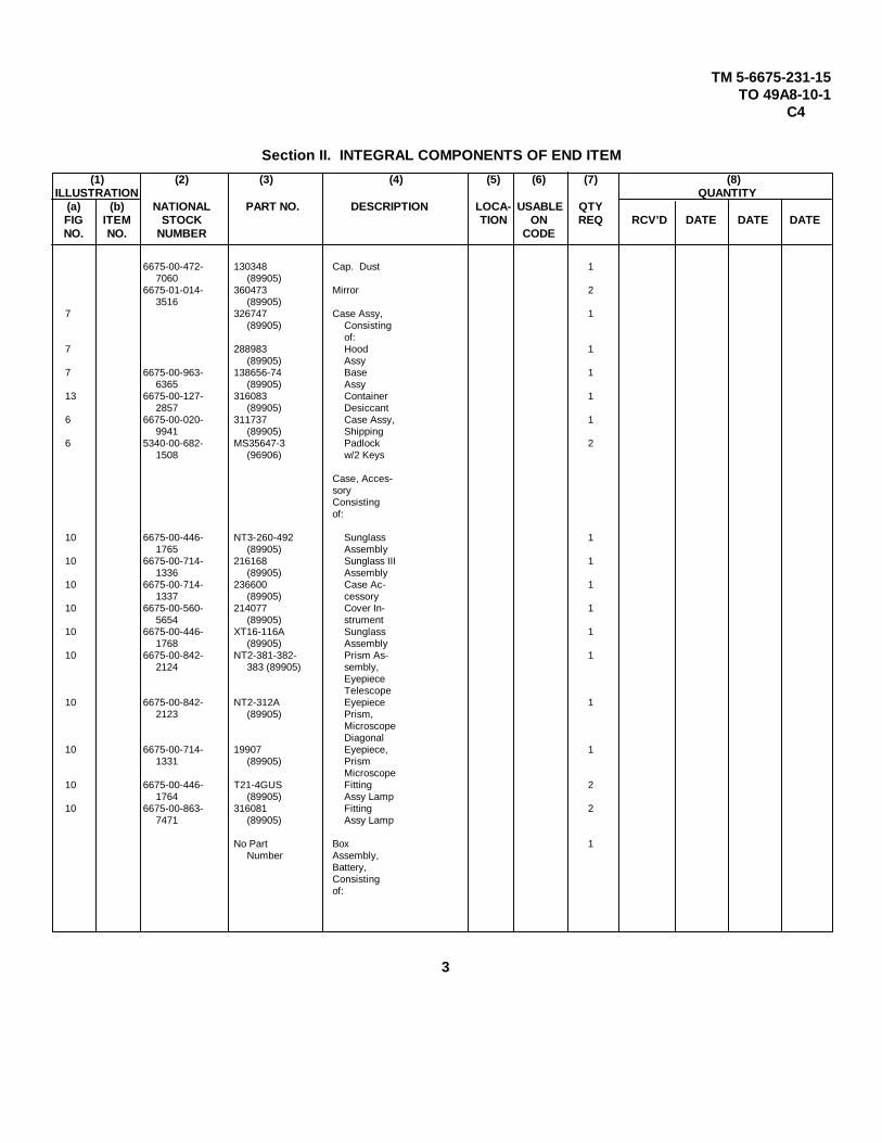
Section II. INTEGRAL COMPONENTS OF END ITEM
(1) (2) (3) (4) (5) (6) (7) (8)ILLUSTRATION QUANTITY
(a) (b) NATIONAL PART NO. DESCRIPTION LOCA- USABLE QTYFIG ITEM STOCK TION ON REQ RCV’D DATE DATE DATENO. NO. NUMBER CODE
6675-00-472- 130348 Cap. Dust 17060 (89905)
6675-01-014- 360473 Mirror 23516 (89905)
7 326747 Case Assy, 1(89905) Consisting
of:7 288983 Hood 1
(89905) Assy7 6675-00-963- 138656-74 Base 1
6365 (89905) Assy13 6675-00-127- 316083 Container 1
2857 (89905) Desiccant6 6675-00-020- 311737 Case Assy, 1
9941 (89905) Shipping6 5340-00-682- MS35647-3 Padlock 2
1508 (96906) w/2 Keys
Case, Acces-soryConsistingof:
10 6675-00-446- NT3-260-492 Sunglass 11765 (89905) Assembly
10 6675-00-714- 216168 Sunglass III 11336 (89905) Assembly
10 6675-00-714- 236600 Case Ac- 11337 (89905) cessory
10 6675-00-560- 214077 Cover In- 15654 (89905) strument
10 6675-00-446- XT16-116A Sunglass 11768 (89905) Assembly
10 6675-00-842- NT2-381-382- Prism As- 12124 383 (89905) sembly,
EyepieceTelescope
10 6675-00-842- NT2-312A Eyepiece 12123 (89905) Prism,
MicroscopeDiagonal
10 6675-00-714- 19907 Eyepiece, 11331 (89905) Prism
Microscope10 6675-00-446- T21-4GUS Fitting 2
1764 (89905) Assy Lamp10 6675-00-863- 316081 Fitting 2
7471 (89905) Assy Lamp
No Part Box 1Number Assembly,
Battery,Consistingof:
33
TM 5-6675-231-15TO 49A8-10-1
C4
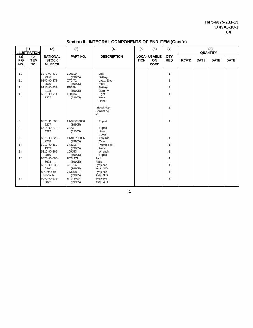
Section II. INTEGRAL COMPONENTS OF END ITEM (Cont’d)
(1) (2) (3) (4) (5) (6) (7) (8)ILLUSTRATION QUANTITY
(a) (b) NATIONAL PART NO. DESCRIPTION LOCA- USABLE QTYFIG ITEM STOCK TION ON REQ RCV’D DATE DATE DATENO. NO. NUMBER CODE
11 6675.00-490- 200819 Box, 19376 (89905) Battery
11 6150-00-378- XT2-72 Lead, Elec- 19500 (89905) trical
11 6135-00-937- EB329 Battery, 24118 (89905) Dummy
11 6675-00-714- 268034 Light 11375 (89905) Assy,
Hand
Tripod Assy 1Consistingof:
9 6675-01-036- 21A00800066 Tripod 12227 (89905)
9 6675-00-378- 3A63 Tripod9525 (89905) Head
Cover9 6675-00-026- 21A00700066 Tool Kit 1
2228 (89905) Case14 5210-00-158- 243915 Plumb bob 1
1353 (89905) Assy14 5120-00-169- 109153 Wrench 1
2880 (89905) Tripod12 6675-00-560- NT3-371 Pack 1
5678 (89905) Rack6675-00-838- XT3-16 Eyepiece 1
0840 (89905) Assy, 24XMounted on 243358 Eyepiece 1Theodolite (89905) Assy, 30X
13 6650-00-838- NT3-305A Eyepiece 10842 (89905) Assy, 40X
4
TM 5-6675-231-15TO 49A8-10-1
C4
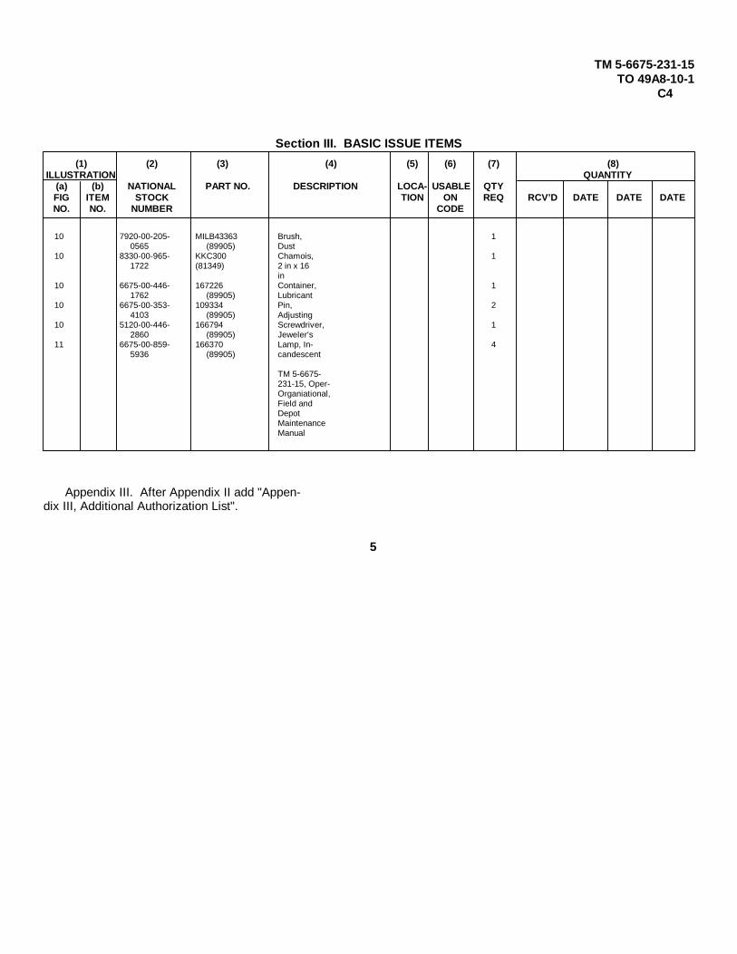
Section III. BASIC ISSUE ITEMS
(1) (2) (3) (4) (5) (6) (7) (8)ILLUSTRATION QUANTITY
(a) (b) NATIONAL PART NO. DESCRIPTION LOCA- USABLE QTYFIG ITEM STOCK TION ON REQ RCV’D DATE DATE DATENO. NO. NUMBER CODE
10 7920-00-205- MILB43363 Brush, 10565 (89905) Dust
10 8330-00-965- KKC300 Chamois, 11722 (81349) 2 in x 16
in10 6675-00-446- 167226 Container, 1
1762 (89905) Lubricant10 6675-00-353- 109334 Pin, 2
4103 (89905) Adjusting10 5120-00-446- 166794 Screwdriver, 1
2860 (89905) Jeweler's11 6675-00-859- 166370 Lamp, In- 4
5936 (89905) candescent
TM 5-6675-231-15, Oper-Organiational,Field andDepotMaintenanceManual
Appendix III. After Appendix II add "Appen-dix III, Additional Authorization List".
55
TM 5-6675-231-15TO 49A8-10-1
C4
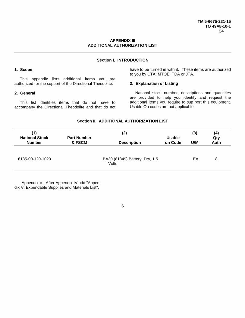
APPENDIX IIIADDITIONAL AUTHORIZATION LIST
Section I. INTRODUCTION
1. Scope
This appendix lists additional items you areauthorized for the support of the Directional Theodolite.
2. General
This list identifies items that do not have toaccompany the Directional Theodolite and that do not
have to be turned in with it. These items are authorizedto you by CTA, MTOE, TDA or JTA.
3. Explanation of Listing
National stock number, descriptions and quantitiesare provided to help you identify and request theadditional items you require to sup port this equipment.Usable On codes are not applicable.
Section II. ADDITIONAL AUTHORIZATION LIST
(1) (2) (3) (4)National Stock Part Number Usable Qty
Number & FSCM Description on Code U/M Auth
6135-00-120-1020 BA30 (81349) Battery, Dry, 1.5 EA 8Volts
Appendix V. After Appendix IV add "Appen-dix V, Expendable Supplies and Materials List".
6
TM 5-6675-231-15TO 49A8-10-1
C4
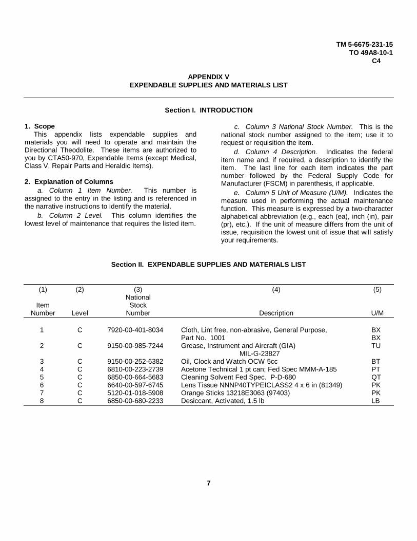
APPENDIX VEXPENDABLE SUPPLIES AND MATERIALS LIST
Section I. INTRODUCTION
1. ScopeThis appendix lists expendable supplies and
materials you will need to operate and maintain theDirectional Theodolite. These items are authorized toyou by CTA50-970, Expendable Items (except Medical,Class V, Repair Parts and Heraldic Items).
2. Explanation of Columnsa. Column 1 Item Number. This number is
assigned to the entry in the listing and is referenced inthe narrative instructions to identify the material.
b. Column 2 Level. This column identifies thelowest level of maintenance that requires the listed item.
c. Column 3 National Stock Number. This is thenational stock number assigned to the item; use it torequest or requisition the item.
d. Column 4 Description. Indicates the federalitem name and, if required, a description to identify theitem. The last line for each item indicates the partnumber followed by the Federal Supply Code forManufacturer (FSCM) in parenthesis, if applicable.
e. Column 5 Unit of Measure (U/M). Indicates themeasure used in performing the actual maintenancefunction. This measure is expressed by a two-characteralphabetical abbreviation (e.g., each (ea), inch (in), pair(pr), etc.). If the unit of measure differs from the unit ofissue, requisition the lowest unit of issue that will satisfyyour requirements.
Section II. EXPENDABLE SUPPLIES AND MATERIALS LIST
(1) (2) (3) (4) (5)National
Item StockNumber Level Number Description U/M
1 C 7920-00-401-8034 Cloth, Lint free, non-abrasive, General Purpose, BXPart No. 1001 BX
2 C 9150-00-985-7244 Grease, Instrument and Aircraft (GIA) TUMIL-G-23827
3 C 9150-00-252-6382 Oil, Clock and Watch OCW 5cc BT4 C 6810-00-223-2739 Acetone Technical 1 pt can; Fed Spec MMM-A-185 PT5 C 6850-00-664-5683 Cleaning Solvent Fed Spec. P-D-680 QT6 C 6640-00-597-6745 Lens Tissue NNNP40TYPEICLASS2 4 x 6 in (81349) PK7 C 5120-01-018-5908 Orange Sticks 13218E3063 (97403) PK8 C 6850-00-680-2233 Desiccant, Activated, 1.5 lb LB
7

TM 5-6675-231-15C4
By Order of the Secretary of the Army:
BERNARD W. ROGERSGeneral, United States Army
Official: Chief of StaffJ. C. PENNINGTON
Brigadier General, United States ArmyThe Adjutant General
Distribution:
To be distributed in accordance with DA Form 12-25A, Operator maintenance requirements for Surveying Equipment.
8

TM 5-6675-231-15TO 49A8-10-1
TECHNICAL MANUAL DEPARTMENTS OF THE ARMYNo. 5-6675-231-15 AND THE AIR FORCETECHNICAL ORDER WASHINGTON 25, D.C., 28 June 1963No. 49A8-10-1
OPERATOR, ORGANIZATIONAL, FIELD AND DEPOT MAINTENANCE MANUAL
THEODOLITE: DIRECTIONAL; 2/10-SEC. DEGREE GRADUATION; 10.2 IN.LONG TELESCOPE W / ACCESSORIES (WILD HEERBRUGG MODEL T-3)
FSN 6675-382-9140
_______
Paragraph PageCHAPTER 1. INTRODUCTION
Section I. General.............................................................................................................................1, 2 3II. Description and data ..........................................................................................................3-5 3
CHAPTER 2. INSTALLATION AND OPERATION INSTRUCTIONSSection I. Service upon receipt of equipment ...................................................................................6-10 9
II. Movement to a new worksite .........................................................................................11, 22 22III. Controls and instruments...............................................................................................13, 14 22IV. Operation of theodolite...................................................................................................15-22 25
CHAPTER 3. OPERATOR AND ORGANIZATIONAL MAINTENANCE INSTRUCTIONSSection I. Operator and organizational maintenance tools and equipment......................................23-25 32
II. Lubrication ....................................................................................................................26, 27 32III. Preventive maintenance services...................................................................................28-30 33IV. Operator's maintenance ................................................................................................31, 32 38V. Troubleshooting .............................................................................................................33-45 38
VI. Carrying case and pack rack ..........................................................................................46-48 39VII. Eyepieces ......................................................................................................................49-52 41
VIII. Star plate .....................................................................................................................53, 54 43IX. Illumination mirrors ......................................................................................................55, 56 43X. Tripod assembly, plumb bob, and tripod wrench ............................................................57-59 44
CHAPTER 4. DEMOLITION OF THEODOLITE TO PREVENT ENEMY USE ......................................60-62 46CHAPTER 5. SHIPMENT AND LIMITED STORAGE
Section I. Shipment within zone of interior ...................................................................................63, 64 47II. Limited storage .............................................................................................................65, 66 47
CHAPTER 6. FIELD AND DEPOT MAINTENANCE INSTRUCTIONSSection I. General.........................................................................................................................67, 58 49
II. Description and data .....................................................................................................69, 70 49III. Special tools and equipment ..........................................................................................71-73 51IV. Troubleshooting .............................................................................................................74-89 55V. Illumination mirrors .......................................................................................................90, 91 56
VI. Collimation level and lever assembly ............................................................................92, 93 57VII. Star plate ......................................................................................................................94, 95 61
VIII. Plate level, vertical circle illumination prism, micrometer circle illumination prism,and inverter prism ....................................................................................................96-100 61
IX. Microscope, telescope, and reticle mirror ...................................................................101-104 65X. Micrometer................................................................................................................ 105, 106 69
XI. Horizontal, vertical, and collimation slow-motion screws ........................................... 107, 108 71XII. Horizontal circle illumination prism and housing cover, horizontal circle prism
carrier, and illumination cable connector .................................................................109-112 73
TAGO 5078A-July1
}
1

Paragraph PageXIII. Horizontal clamp, clamp ring, contact ring, outer vertical axis, and horizontal circle 113-115 76XIV. Leveling screws, horizontal circle drive, illumination socket, and horizontal circle
housing ...................................................................................................................116-120 79XV. Right side axis bearing, vertical clamp, telescope axis, left side bearing, vertical
circle, vertical circle housing, and vertical circle prism carrier .................................121-124 81XVI. U-standard and inner vertical axis ............................................................................. 125, 126 86
XVII. Illumination system ...................................................................................................127-129 88APPENDIX I. REFERENCES ....................................................................................................................... 91
II. MAINTENANCE ALLOCATION CHART.................................................................................. 92III. BASIC ISSUE ITEMS LIST .................................................................................................... 97
INDEX...........................................................................................................................................................................100
AGO 5078A
2

CHAPTER 1
INTRODUCTION
Section I. GENERAL
1. Scopea. These instructions are for the use of the
personnel to whom the Wild Heerbrugg Model T-3Theodolite is issued. Chapters 1 through 5 provideinformation on the operation, preventive maintenanceservices, and organizational maintenance of theequipment, accessories, components, and attachments.Chapter 6 provides information for field and depotmaintenance (3d, 4th, and 5th echelons). This manualalso provides descriptions of the main units and theirfunctions in relationship to other components.
b. Appendix I contains a list of publicationsapplicable to this manual. Appendix II contains themaintenance allocation chart. Appendix III contains thelist of basic issue items authorized the operator of thisequipment. The organizational, field, and depotmaintenance repair parts and special tool lists are listedin TM 5-6675-231-25P.
c. Numbers in parentheses on illustrations indicatequantity. Numbers preceding nomenclature callouts onillustrations indicate the preferred maintenancesequence.
d. Report all deficiencies in this manual on DAForm 2028. Submit recommendations for changes,additions, or deletions to the Commanding Officer, U.S. Army Mobility Support Center, ATTN: SMOMS-MSP. O. Box 119, Columbus 16, Ohio. Directcommunication is authorized.
e. Report all equipment improvementrecommendations as prescribed by TM 38-750.
2. Record and Report FormsFor record and report forms applicable to the
operator and organizational maintenance, refer to TM38-750.
Note
Applicable forms, excludingStandard Form 46, which is carriedby the operator, shall be kept in acanvas bag mounted on theequipment.
Section II. DESCRIPTION AND DATA
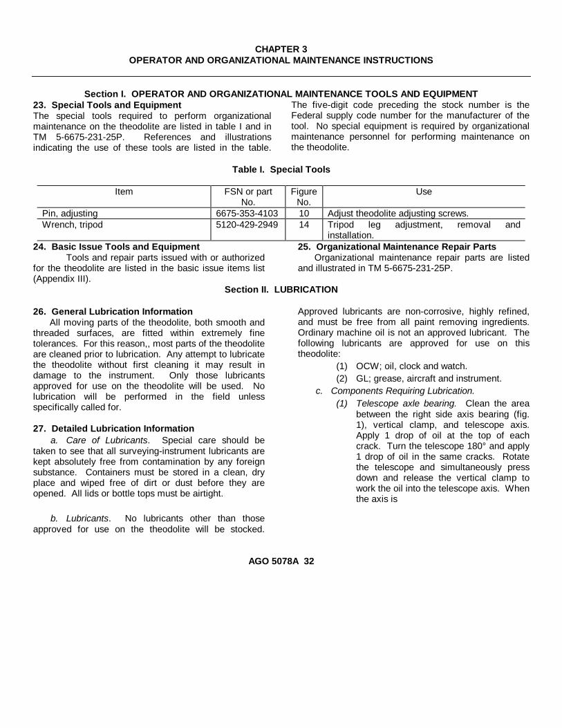
3. DescriptionThe Wild Heerbrugg Model T-3 Theodolite (figs. 1
through 4) is a precision, directional type surveying andtracking instrument. It has both vertical and horizontalcircle scales, calibrated in degrees for reading the valueof angles. Such readings are observed through themicroscope eyepiece (fig. 3). A micrometer circle (fig.4) is provided for the interpolation of angle valuereadings to 2/10 second degree accuracy. Thehorizontal circle housing contains the 3 leveling screws(fig. 1) to which a star plate (fig. 1) for tripod mountingis attached.
Illumination of the vertical, horizontal, and micrometercircles during daylight operation is accomplished byadjusting the illumination mirrors (figs. 1 and 2). Abattery-powered electrical illumination system isprovided for night operation. Eyepiece prisms forattachment to the telescope and microscope eyepiecesduring high-angle and astronomical observations arecontained in the accessory case. The telescope isequipped with a 30-power eyepiece, optional eyepiecesof 24 and 40 power, which are stowed in the carryingcase base, and may be installed when necessary.
AGO 5078A3
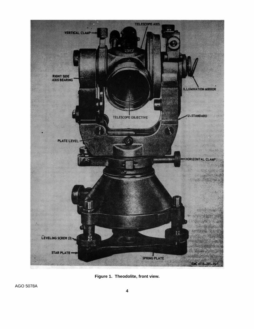
Figure 1. Theodolite, front view.
AGO 5078A4
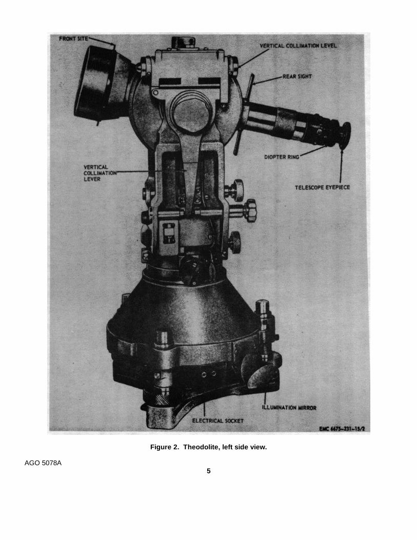
Figure 2. Theodolite, left side view.
AGO 5078A5
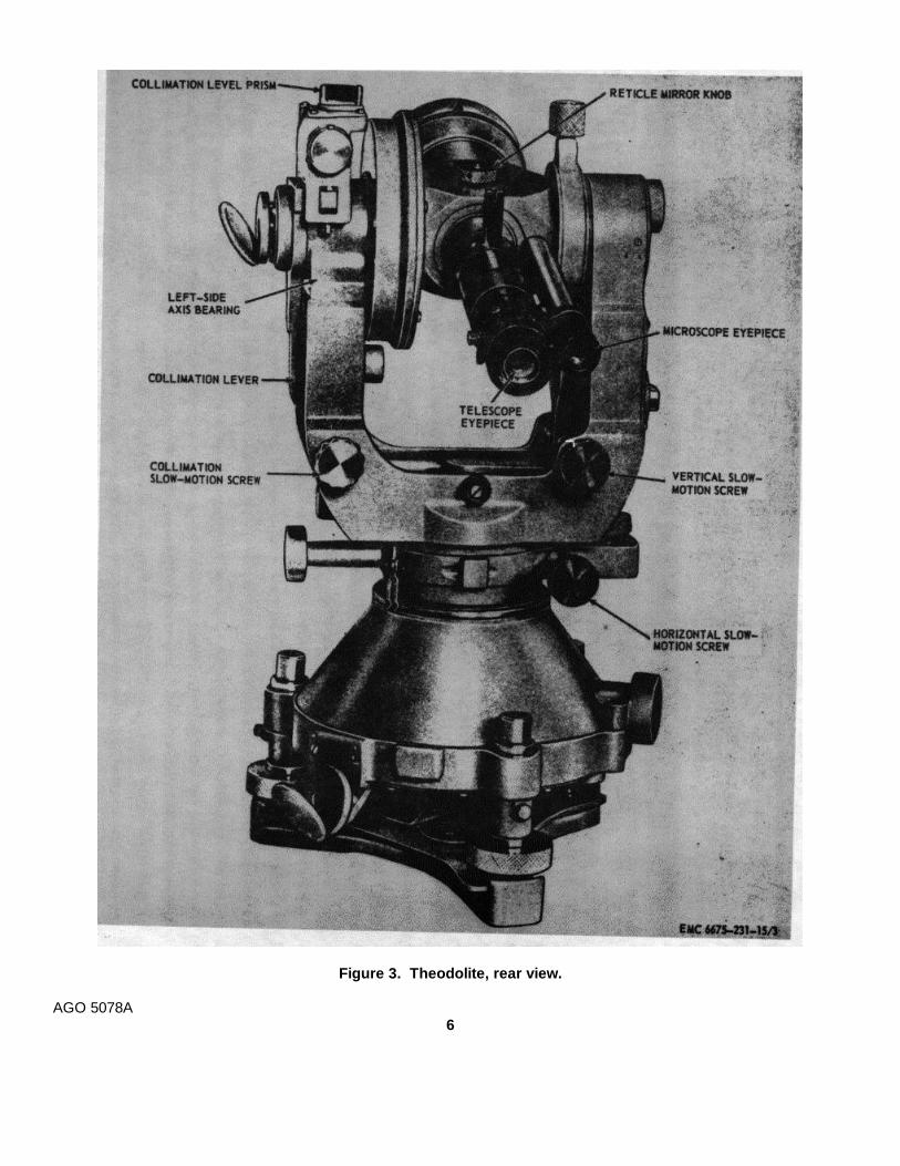
Figure 3. Theodolite, rear view.
AGO 5078A6
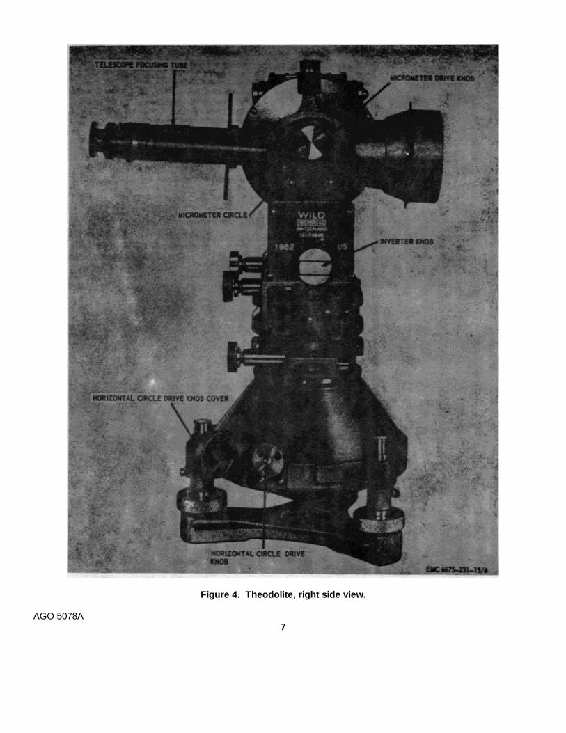
Figure 4. Theodolite, right side view.
AGO 5078A7
4. Identification and Tabulated Dataa. Identification. The theodolite and carrying case
have the following identification markings:(1) Theodolite. The manufacturer's name,
model, and serial number are engravedon the inverter prism cover.
(2) Carrying case hood. The manufacturer'sname, model, and serial number arestenciled on the carrying case hood.
b. Tabulated Data.(1) General.
Manufacturer..........................Wild Heerbrugg Ltd.Heerbrugg, Switzerland.
Model.....................................T-3Telescope ..............................24, 30, 40X (power)Telescope length ...................10.25 in. (inches)Glass circles...........................360° (degrees)
Horizontal circle 5.5 in.diameter.
Horizontal circle 4 min. (minutes)graduation.
Vertical circle diameter 3.8 in.Vertical circle 8 min.
graduation.Micrometer circle 0.2" (second)
graduation.Clear aperture of objective .....2.4 in.Plate level sensitivity.............. 7" per m (millimeter)Collimation level sensitivity ....12" per 2 mmCoincidence adjustment of .....0.2"
collimation level.Microscope magnification.......37X
(2) Dimensions and weights.Tripod (nontelescopic)............5 feetInstrument .............................25 lb (pounds)Carrying case.........................8 lbPack rack ..............................4 lbTripod ....................................16 lb
5. Difference in ModelsThis manual covers only the Wild Heerbrugg Model
T-3 Theodolite. No known unit differences exist for themodel covered by this manual.
AGO 5078A8

CHAPTER 2
INSTALLATION AND OPERATION INSTRUCTIONS
Section I. SERVICE UPON RECEIPT OF EQUIPMENT
6. Unloading the Equipmenta. Theodolite. The theodolite is shipped in a
shipping case (fig. 5). Unloading the instrumentpresents no problem since the loaded weight of theshipping case is only 68 pounds.
Caution
Exercise care while unloading toprevent damage to the theodolite.
b. Tripod and Accessories. The tripod andaccessories used with the theodolite are shipped in aseparate shipping container (fig. 5). The gross weightof the boxed tripod and accessories is 87 pounds. Ahandtruck or manpower may be used to unload theaccessory container.
7. Unpacking the Equipmenta. Theodolite and Carrying Case
(1) Remove the 2 locks, unfasten the 2captive screws, and open the shippingcase door (fig. 6).
(2) Remove the theodolite carrying case fromthe shipping case.
(3) Refer to figure 7 and remove the carryingcase hood.
(4) Refer to figure 8 and remove the carryingcase base.
Caution
Do not grasp the left side axisbearing when lifting the theodolite.Failure to observe this caution willplace undue pressure on thecollimation lever and makereadjustment necessary.
b. Tripod.(1) Remove the cover from the tripod and
accessories shipping container (fig. 5).(2) Remove the tripod assembly (fig. 9) from
the shipping container.c. Accessory Case. Remote the accessory case
(fig. 10) from the shipping container.
d. Battery Box. Remove the battery box (fig. 11)from the shipping container.
e. Pack Rack. Remove the pack rack (fig. 12)from the shipping container.
8. Inspecting and Servicing the Equipmenta. General. Perform the daily preventive
maintenance services (par. 29).b. Carrying Case.
(1) Inspect the carrying case (fig. 6) fordents, cracks, rust, defective clamps, andcarrying strap.
(2) Inspect the telescope eyepieces (fig.13) for scratched or cracked lens, anddamaged threads.
(3) Inspect the light housings (fig. 13) forbroken glass and corroded or defectivecontacts.
(4) Inspect the carrying case desiccant (fig.13) for discoloration.
Note
Desiccant should be blue in color.Pink desiccant indicates moisturesaturation and must be dehydratedor replaced.
c. Theodolite.(1) Visually inspect the theodolite for broken
or missing parts, cracked or scratchedlens and mirrors, loose or missinghardware, and other indications ofdamage.
(2) Rotate the three leveling screws (fig.1) and inspect for rough travel and
instability.(3) Inspect the vertical clamp (fig. 1) and
horizontal clamp (fig. 1) for improperoperation.
(4) Inspect the horizontal slow-motion screw(fig. 3), vertical slow-motion screw (fig.3), and combination slow motion screw(fig. 3) for improper operation.
AGO 5078A9
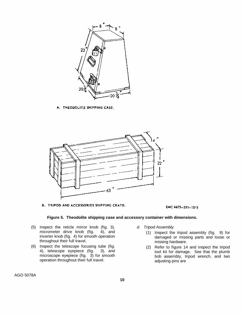
Figure 5. Theodolite shipping case and accessory container with dimensions.
(5) Inspect the reticle mirror knob (fig. 3),micrometer drive knob (fig. 4), andinverter knob (fig. 4) for smooth operationthroughout their full travel.
(6) Inspect the telescope focusing tube (fig.4), telescope eyepiece (fig. 3), andmicroscope eyepiece (fig. 3) for smoothoperation throughout their full travel.
d. Tripod Assembly.(1) Inspect the tripod assembly (fig. 9) for
damaged or missing parts and loose ormissing hardware.
(2) Refer to figure 14 and inspect the tripodtool kit for damage. See that the plumbbob assembly, tripod wrench, and twoadjusting pins are
AGO 5078A10

Figure 6. Theodolite carrying case, removal and installation.
contained in the case and are inserviceable condition.
e. Accessory Case.(1) Inspect the accessory case for damage
and defective zipper and snaps. Makecertain that the case contains thecomponents shown by figure 10.
(2) Inspect the telescope eyepiece prism,microscope eyepiece prism, and thetelescope eyepiece sunglass forscratches, cracks, and damaged threads.
(3) Inspect the light housings for broken glassand corroded or defective contacts.
f. Battery Box.(1) Inspect the battery box (fig. 11) for
damage, rust, and defective clamps andcarrying handle. Make certain the boxcontains all the components shown infigure 11.
(2) Turn the rheostat knob (fig. 11) throughits full travel. The movement should besmooth and free of binding.
AGO 5078A11
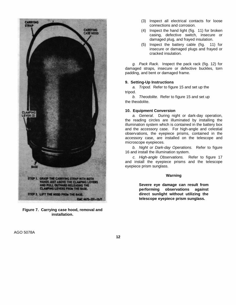
Figure 7. Carrying case hood, removal andinstallation.
(3) Inspect all electrical contacts for looseconnections and corrosion.
(4) Inspect the hand light (fig. 11) for brokencasing, defective switch, insecure ordamaged plug, and frayed insulation.
(5) Inspect the battery cable (fig. 11) forinsecure or damaged plugs and frayed orcracked insulation.
g. Pack Rack. Inspect the pack rack (fig. 12) fordamaged straps, insecure or defective buckles, tornpadding, and bent or damaged frame.
9. Setting-Up Instructionsa. Tripod. Refer to figure 15 and set up the
tripod.b. Theodolite. Refer to figure 15 and set up
the theodolite.
10. Equipment Conversiona. General. During night or dark-day operation,
the reading circles are illuminated by installing theillumination system which is contained in the battery boxand the accessory case. For high-angle and celestialobservations, the eyepiece prisms, contained in theaccessory case, are installed on the telescope andmicroscope eyepieces.
b. Night or Dark-day Operations. Refer to figure16 and install the illumination system.
c. High-angle Observations. Refer to figure 17and install the eyepiece prisms and the telescopeeyepiece prism sunglass.
Warning
Severe eye damage can result fromperforming observations againstdirect sunlight without utilizing thetelescope eyepiece prism sunglass.
AGO 5078A12
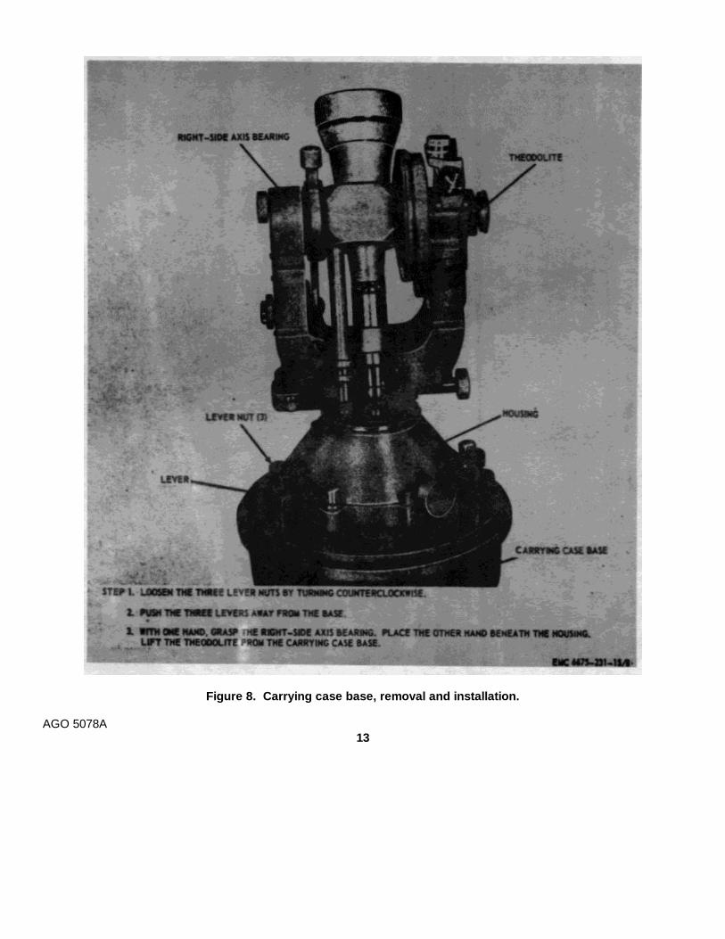
Figure 8. Carrying case base, removal and installation.
AGO 5078A13
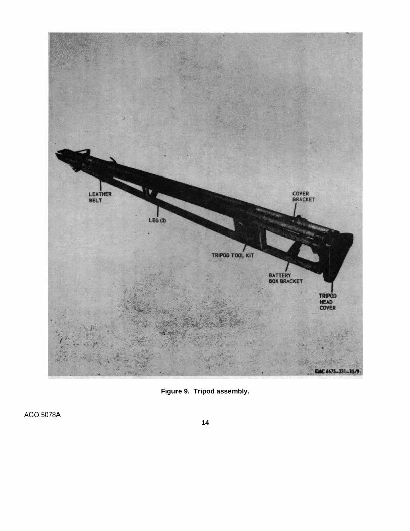
Figure 9. Tripod assembly.
AGO 5078A14
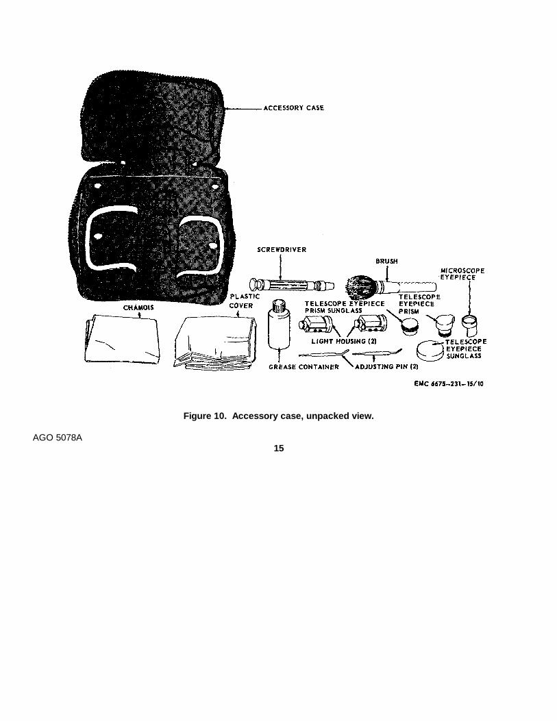
Figure 10. Accessory case, unpacked view.
AGO 5078A15

Figure 11. Battery box, unpacked view.
AGO 5078A16
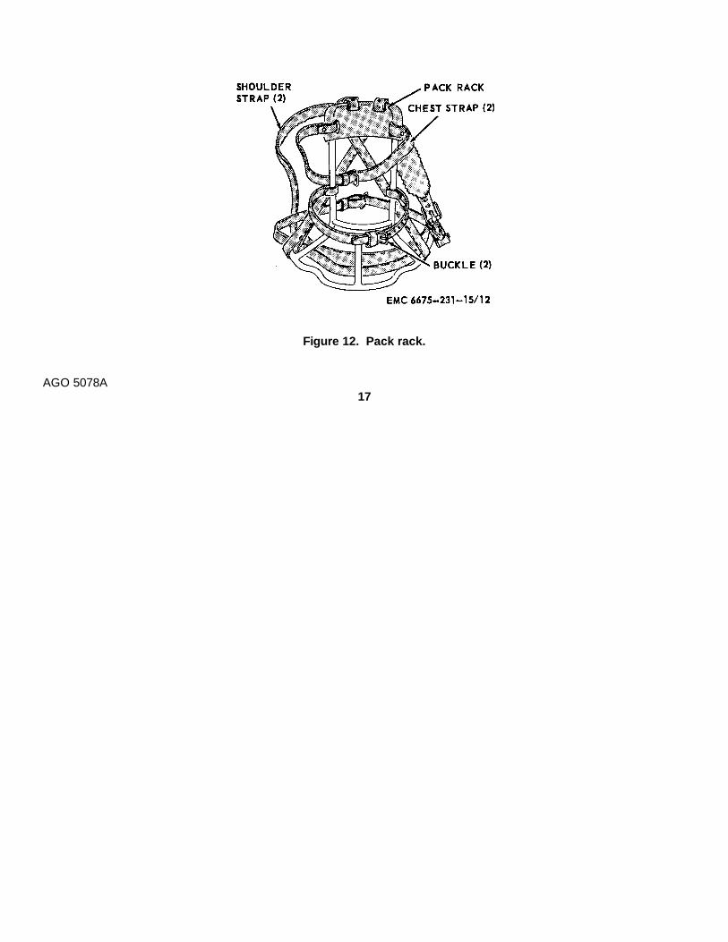
Figure 12. Pack rack.
AGO 5078A17
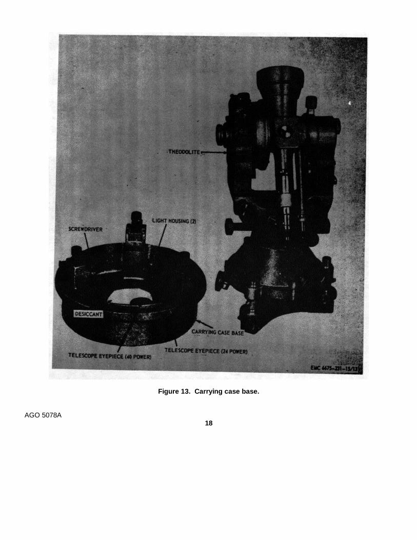
Figure 13. Carrying case base.
AGO 5078A18
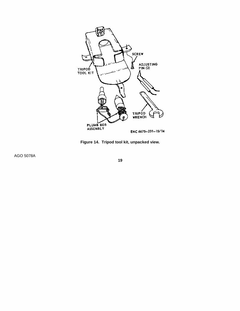
Figure 14. Tripod tool kit, unpacked view.
AGO 5078A19

Figure 15. Tripod and theodolite, setting-up instructions.
AGO 5078A20
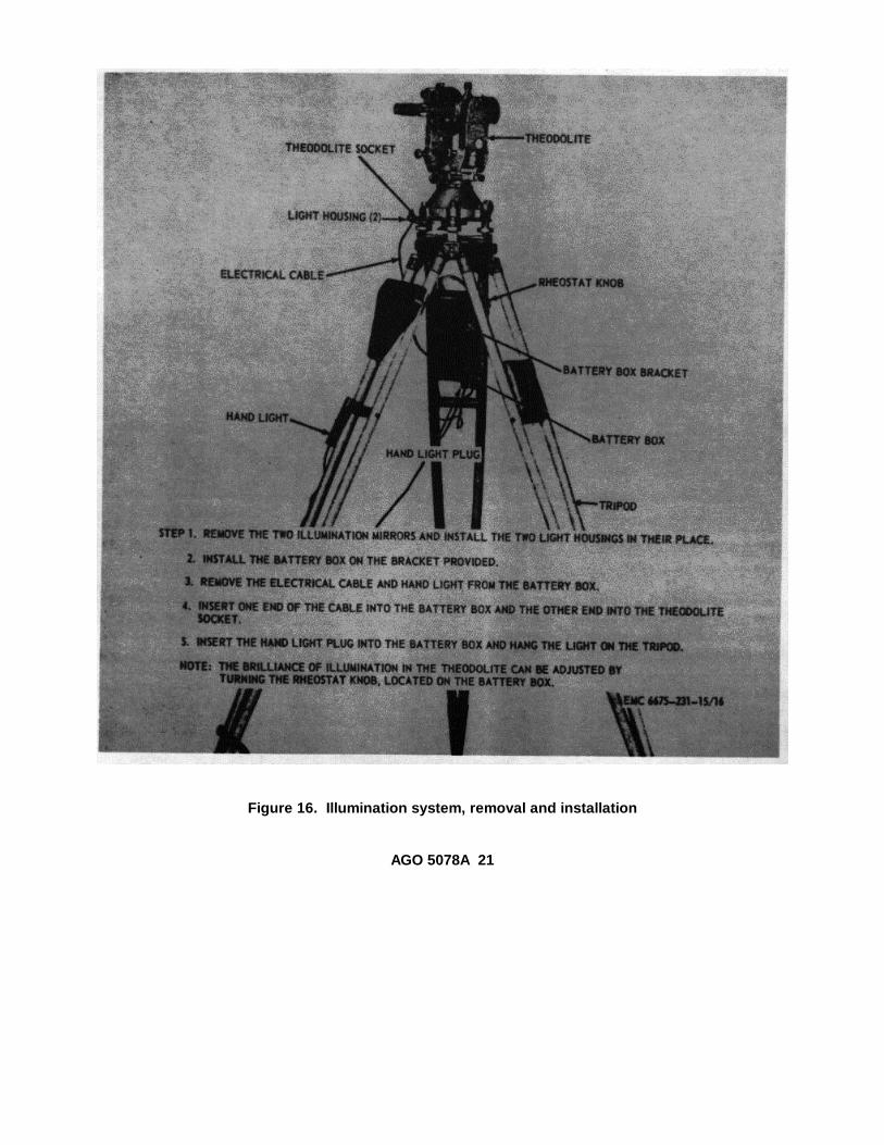
Figure 16. Illumination system, removal and installation
AGO 5078A 21

Figure 17. Theodolite eyepiece prisms and sunglass, removal and installationSection II. MOVEMENT TO A NEW WORKSITE
11. Dismantling for Movement
a. Short Distances. For short distances in cleared,level areas, the operator may carry the instrumentmounted on the tripod. If the instrument is carried whilemounted on the tripod, the operator should not carry it inany position other than upright.
CautionExercise care when moving thetheodolite mounted on tripod.Handle the instrument carefully.Never subject it to bumps, jars, orshocks. Never leave the instrumentunattended for long periods of timeunless it is returned to the carryingcase. Never carry the instrumentover the shoulder.
b. Long Distances.(1) When the theodolite must be moved for
long distances or over rough terrain, theinstrument should be transported in thecarrying case (fig. 6).
(2) Handle the carrying case carefully toavoid sudden jolts, continued vibration, orother shocks that might damage thedelicate parts of the instrument.
(3) Do not drop the carrying case into avehicle or on the ground duringtransportation.Note. If the carrying case is accidentallydropped, the instrument should bethoroughly inspected for damage.
(4) If the theodolite is to be carried longdistances by manpower, the pack rack(fig. 12) should be utilized.
12. Setting-Up Instructions After MovementRefer to paragraph 9 for setting-up instructions after
movement.
Section III. CONTROLS AND INSTRUMENTS13. GeneralThis section describes, locates, illustrates, and furnishesthe operator or organizational maintenance personnelsufficient information about the various controls andinstruments for proper operation of the theodolite.
14. Controls and InstrumentsThe purpose and normal settings of all controls andinstruments will be found in figure 18.
AGO 5078A 22
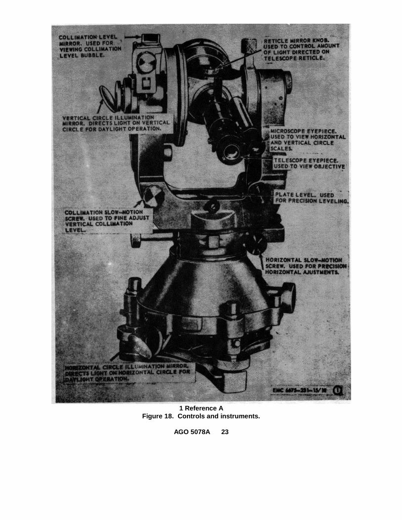
1 Reference AFigure 18. Controls and instruments.
AGO 5078A 23
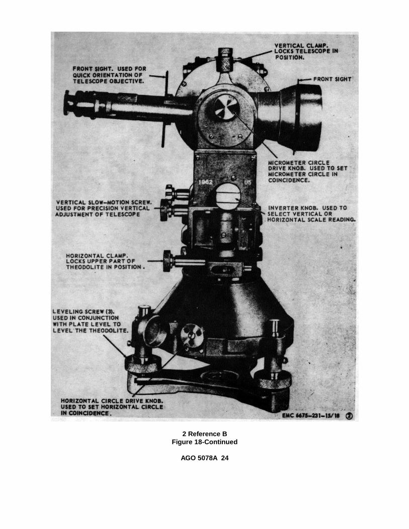
2 Reference BFigure 18-Continued
AGO 5078A 24
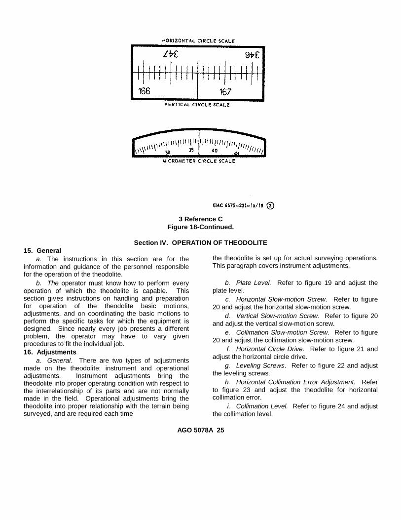
3 Reference CFigure 18-Continued.
Section IV. OPERATION OF THEODOLITE15. General
a. The instructions in this section are for theinformation and guidance of the personnel responsiblefor the operation of the theodolite.
b. The operator must know how to perform everyoperation of which the theodolite is capable. Thissection gives instructions on handling and preparationfor operation of the theodolite basic motions,adjustments, and on coordinating the basic motions toperform the specific tasks for which the equipment isdesigned. Since nearly every job presents a differentproblem, the operator may have to vary givenprocedures to fit the individual job.16. Adjustments
a. General. There are two types of adjustmentsmade on the theodolite: instrument and operationaladjustments. Instrument adjustments bring thetheodolite into proper operating condition with respect tothe interrelationship of its parts and are not normallymade in the field. Operational adjustments bring thetheodolite into proper relationship with the terrain beingsurveyed, and are required each time
the theodolite is set up for actual surveying operations.This paragraph covers instrument adjustments.
b. Plate Level. Refer to figure 19 and adjust theplate level.
c. Horizontal Slow-motion Screw. Refer to figure20 and adjust the horizontal slow-motion screw.
d. Vertical Slow-motion Screw. Refer to figure 20and adjust the vertical slow-motion screw.
e. Collimation Slow-motion Screw. Refer to figure20 and adjust the collimation slow-motion screw.
f. Horizontal Circle Drive. Refer to figure 21 andadjust the horizontal circle drive.
g. Leveling Screws. Refer to figure 22 and adjustthe leveling screws.
h. Horizontal Collimation Error Adjustment. Referto figure 23 and adjust the theodolite for horizontalcollimation error.
i. Collimation Level. Refer to figure 24 and adjustthe collimation level.
AGO 5078A 25

Figure 19. Plate level, adjustment.
17. Theodolite Operationa. Set up the theodolite on the tripod (par. 9).b. If necessary, install the illumination system (par.
10).Note
To operate the illumination system,position the rheostat knob untildesired brilliance is obtained. Placethe hand light switch in the ONposition.
c. Install the eyepiece prisms as necessary (par.10).
d. Install the telescope eyepiece or telescopeeyepiece prism sunglass as necessary (par. 49).
e. Perform the daily preventive maintenanceservices (par. 29).
f. Refer to figure 25 and level the theodolite.Warning
Severe eye damage can result fromperforming observations againstdirect sunlight without utilizing thetelescope sunglass.
g. Focus the telescope as follows:(1) Direct the telescope toward a uniformly
light background. Turn the diopter ring on the telescopeeyepiece (fig. 2) until the crosslines are sharp andblack.
NoteObserve the setting on the diopterring (fig. 2). This setting will remainconstant for the same observer butwill vary for other observers.
(2) Turn the telescope focusing tube (fig. 4)to bring into view a clear image of the object beingsighted.
h. The horizontal and vertical circle reading scalesare both observed through the microscope eyepiece (fig.3). When the rib of the inverter knob (fig 4) is in ahorizontal position, the horizontal circle image appearsin the upper window. When the inverter knob is turnedwith the rib in the vertical position, the vertical circleimage appears in the lower window. Simultaneouslywith either of the circle images, the image of theseconds scale is always visible in the lower window.18. Operation in Extreme Cold (Below 0°F.)
With proper precautions and servicing, thetheodolite can be used in extreme cold. Its use islimited only by the endurance of operating personneland conditions affecting visibility. The theodolite shouldbe kept out-of-doors or in unheated buildings for shortperiods of nonuse. Extreme temperature changes willinduce internal stresses affecting accuracy and lensesand prisms may become fogged. Theodolites to beused under conditions of extreme cold should becleaned and all lubricants removed before being used.Snowfall, winds, and refraction of light are some of theconditions encountered at low temperatures.
CautionAvoid subjecting the theodolite tosudden changes in temperature.
19. Operation in Extreme HeatOperation of the theodolite in extreme heat and
under the direct rays of the sun can cause
AGO 5078A 26
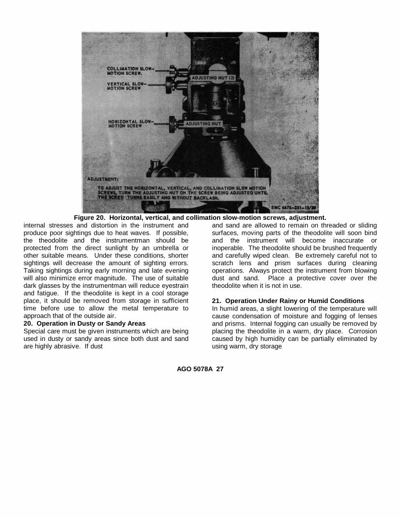
Figure 20. Horizontal, vertical, and collimation slow-motion screws, adjustment.internal stresses and distortion in the instrument andproduce poor sightings due to heat waves. If possible,the theodolite and the instrumentman should beprotected from the direct sunlight by an umbrella orother suitable means. Under these conditions, shortersightings will decrease the amount of sighting errors.Taking sightings during early morning and late eveningwill also minimize error magnitude. The use of suitabledark glasses by the instrumentman will reduce eyestrainand fatigue. If the theodolite is kept in a cool storageplace, it should be removed from storage in sufficienttime before use to allow the metal temperature toapproach that of the outside air.20. Operation in Dusty or Sandy AreasSpecial care must be given instruments which are beingused in dusty or sandy areas since both dust and sandare highly abrasive. If dust
and sand are allowed to remain on threaded or slidingsurfaces, moving parts of the theodolite will soon bindand the instrument will become inaccurate orinoperable. The theodolite should be brushed frequentlyand carefully wiped clean. Be extremely careful not toscratch lens and prism surfaces during cleaningoperations. Always protect the instrument from blowingdust and sand. Place a protective cover over thetheodolite when it is not in use.
21. Operation Under Rainy or Humid ConditionsIn humid areas, a slight lowering of the temperature willcause condensation of moisture and fogging of lensesand prisms. Internal fogging can usually be removed byplacing the theodolite in a warm, dry place. Corrosioncaused by high humidity can be partially eliminated byusing warm, dry storage
AGO 5078A 27
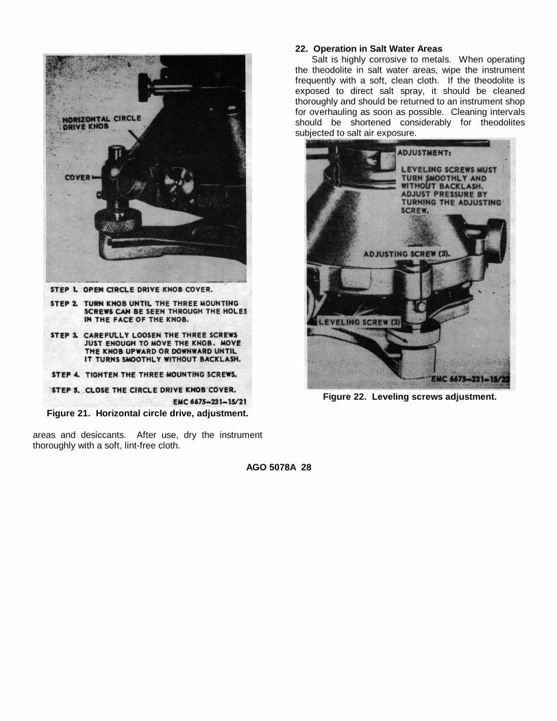
Figure 21. Horizontal circle drive, adjustment.
areas and desiccants. After use, dry the instrumentthoroughly with a soft, lint-free cloth.
22. Operation in Salt Water AreasSalt is highly corrosive to metals. When operating
the theodolite in salt water areas, wipe the instrumentfrequently with a soft, clean cloth. If the theodolite isexposed to direct salt spray, it should be cleanedthoroughly and should be returned to an instrument shopfor overhauling as soon as possible. Cleaning intervalsshould be shortened considerably for theodolitessubjected to salt air exposure.
Figure 22. Leveling screws adjustment.
AGO 5078A 28

Figure 23. Horizontal collimation error, adjustment.
AGO 5078A 29
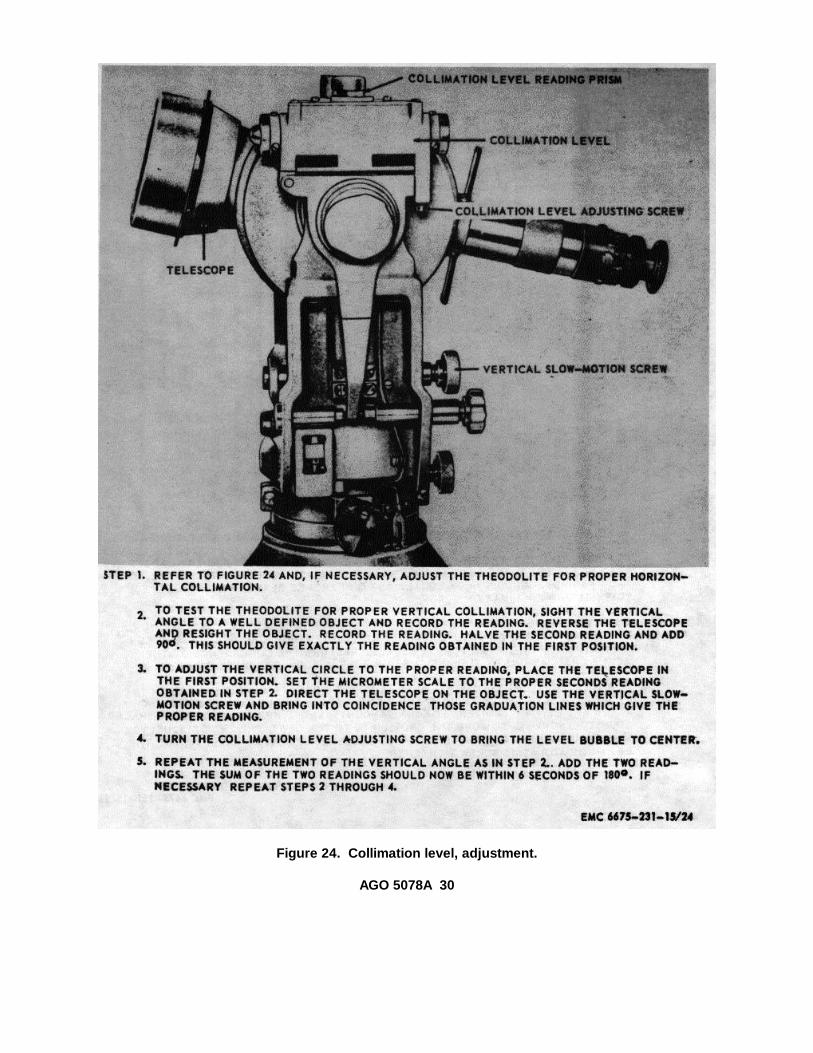
Figure 24. Collimation level, adjustment.
AGO 5078A 30
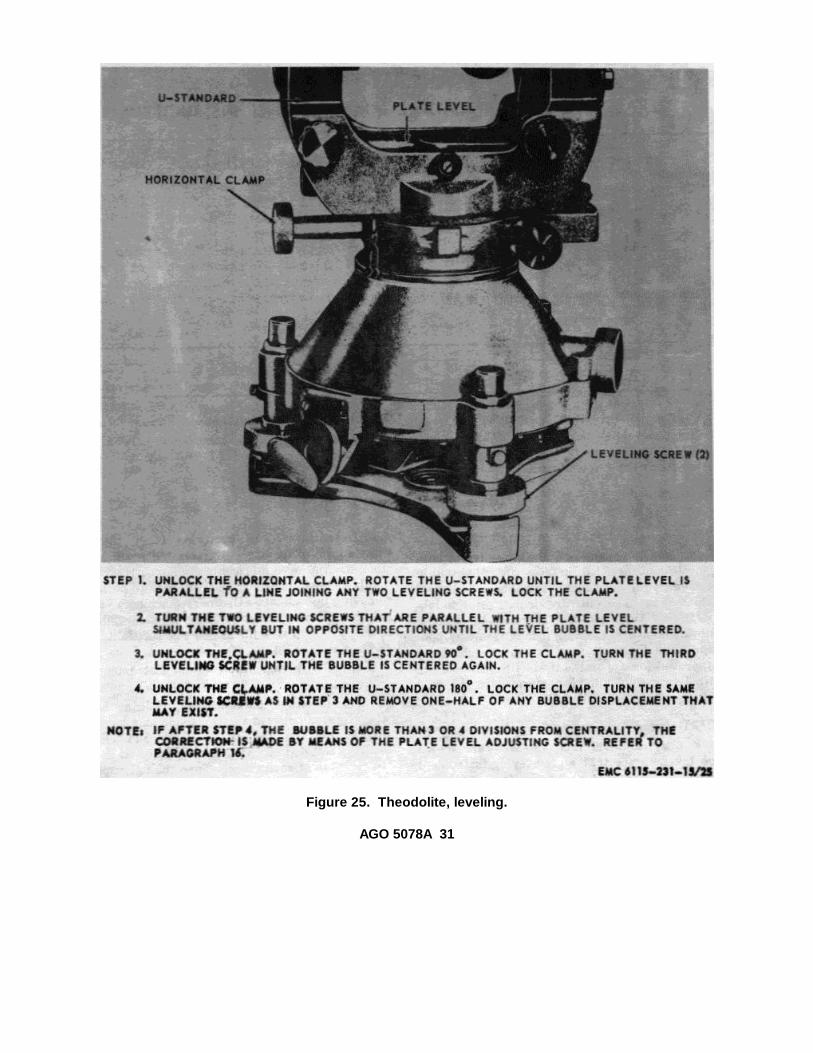
Figure 25. Theodolite, leveling.
AGO 5078A 31
CHAPTER 3OPERATOR AND ORGANIZATIONAL MAINTENANCE INSTRUCTIONS
Section I. OPERATOR AND ORGANIZATIONAL MAINTENANCE TOOLS AND EQUIPMENT23. Special Tools and EquipmentThe special tools required to perform organizationalmaintenance on the theodolite are listed in table I and inTM 5-6675-231-25P. References and illustrationsindicating the use of these tools are listed in the table.
The five-digit code preceding the stock number is theFederal supply code number for the manufacturer of thetool. No special equipment is required by organizationalmaintenance personnel for performing maintenance onthe theodolite.
Table I. Special Tools
Item FSN or partNo.
FigureNo.
Use
Pin, adjusting 6675-353-4103 10 Adjust theodolite adjusting screws.Wrench, tripod 5120-429-2949 14 Tripod leg adjustment, removal and
installation.24. Basic Issue Tools and Equipment
Tools and repair parts issued with or authorizedfor the theodolite are listed in the basic issue items list(Appendix III).
25. Organizational Maintenance Repair PartsOrganizational maintenance repair parts are listed
and illustrated in TM 5-6675-231-25P.
Section II. LUBRICATION
26. General Lubrication InformationAll moving parts of the theodolite, both smooth and
threaded surfaces, are fitted within extremely finetolerances. For this reason,, most parts of the theodoliteare cleaned prior to lubrication. Any attempt to lubricatethe theodolite without first cleaning it may result indamage to the instrument. Only those lubricantsapproved for use on the theodolite will be used. Nolubrication will be performed in the field unlessspecifically called for.
27. Detailed Lubrication Informationa. Care of Lubricants. Special care should be
taken to see that all surveying-instrument lubricants arekept absolutely free from contamination by any foreignsubstance. Containers must be stored in a clean, dryplace and wiped free of dirt or dust before they areopened. All lids or bottle tops must be airtight.
b. Lubricants. No lubricants other than thoseapproved for use on the theodolite will be stocked.
Approved lubricants are non-corrosive, highly refined,and must be free from all paint removing ingredients.Ordinary machine oil is not an approved lubricant. Thefollowing lubricants are approved for use on thistheodolite:
(1) OCW; oil, clock and watch.(2) GL; grease, aircraft and instrument.
c. Components Requiring Lubrication.(1) Telescope axle bearing. Clean the area
between the right side axis bearing (fig.1), vertical clamp, and telescope axis.Apply 1 drop of oil at the top of eachcrack. Turn the telescope 180° and apply1 drop of oil in the same cracks. Rotatethe telescope and simultaneously pressdown and release the vertical clamp towork the oil into the telescope axis. Whenthe axis is
AGO 5078A 32
thoroughly lubricated, wipe off the excess oil with aclean, lint-free cloth.
(2) Collimation lever bearing. Place 1 drop ofoil at the top of the crack between thecollimation lever (fig. 3) and the left sideaxis bearing (fig. 3). Work the oil into thecrack by alternately pushing and releasingthe lower part of the collimation leveragainst the spring of the collimation slow-motion screw (fig. 3). Wipe off all theexcess oil with a clean, lint-free cloth.
(3) Leveling screws. Turn the leveling screw(fig. 1) outward to the extreme length ofits travel. Clean it thoroughly with aclean, lint-free cloth. Lubricate sparinglyand run the screw through its travelseveral times to distribute the lubricantevenly. Wipe off all excess lubricant.Lubricate the other two leveling screws ina similar manner.
(4) Spring plate. The sloped sides of thespring plate (fig. 1), which contact theleveling screws to hold them securelyagainst the star plate (fig. 1), should be
lubricated sparingly as required. Removethe star plate (par. 54). Apply lubricantsparingly to the sloped edges of theopenings in the spring plate (fig. 1).Install the star plate (par. 54).
(5) Horizontal circle drive knob cover hinge.Apply 1 drop of oil to the hinge pin in thehinge of the horizontal circle drive knobcover (fig. 4). Carefully work the coverforward, backward, up, and down todistribute the oil over the workingsurfaces. Wipe off all excess oil with aclean, lint-free cloth.
d. Lubrication Procedure. Cleaning and lubricationservices, which require partial or complete disassemblyof the instrument, must be performed in the dust-freeatmosphere of an instrument repair shop and only byqualified personnel. Disassembling the instrumentunder other conditions, especially where dust might filterinto recesses, will do more harm than good. Since thelubricants must be applied sparingly, never use acontainer with a spout, such as an oil can, to squirt oil onparts or into assemblies.
Section III. PREVENTIVE MAINTENANCE SERVICES28. GeneralTo insure that the theodolite is ready for operation at alltimes, it must be inspected systematically, so thatdefects may be discovered and corrected before theyresult in serious damage or failure. The necessarypreventive maintenance services to be performed arelisted in paragraphs 29 and 30. The items numbersindicate the sequence of minimum inspectionrequirements. Defects discovered during operation ofthe unit shall be noted for future correction, to be madeas soon as operation has ceased. Stop operationimmediately if a deficiency is noted during operation,which would damage the equipment if operation werecontinued. All deficiencies and shortcomings will berecorded together with the corrective action taken on DAForm 2404 (Equipment Inspection and MaintenanceWorksheet) at the earliest possible opportunity.
29. Daily Preventive Maintenance Services
This paragraph contains an illustrated tabulatedlisting of preventive maintenance services which mustbe performed by the operator. The item numbers arelisted consecutively and indicate the sequence ofminimum requirements. Refer to Figure 26 for the dailypreventive maintenance services.30. Quarterly Preventive Maintenance Services
a. This paragraph contains an illustrated tabulatedlisting of preventive maintenance services which mustbe performed by organizational maintenance personnelat quarterly intervals. A quarterly interval is equal to 3calendar months, or 250 hours of operation, whicheveroccurs first.
b. The item numbers are listed consecutively andindicate the sequence of minimum requirements. Referto figure 27 for quarterly preventive maintenanceservices
AGO 5078A 33
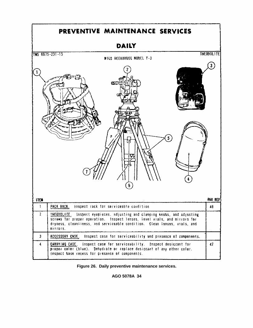
Figure 26. Daily preventive maintenance services.
AGO 5078A 34
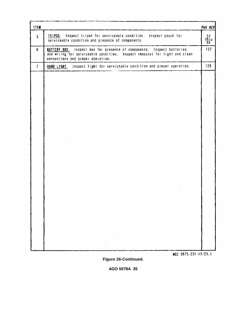
Figure 26-Continued.
AGO 5078A 35

Figure 27. Quarterly preventive maintenance services.
AGO 5078A 36

Figure 27-Continued.
AGO 5078A 37
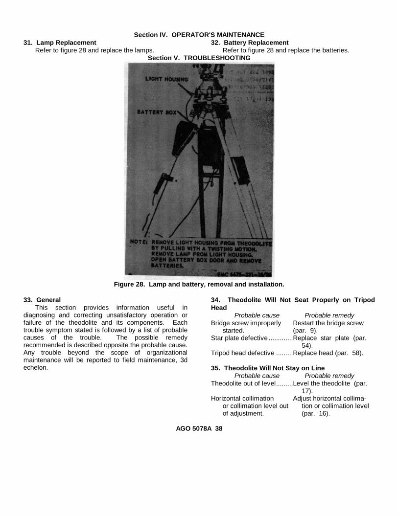
Section IV. OPERATOR'S MAINTENANCE31. Lamp Replacement
Refer to figure 28 and replace the lamps.32. Battery Replacement
Refer to figure 28 and replace the batteries.Section V. TROUBLESHOOTING
Figure 28. Lamp and battery, removal and installation.
33. GeneralThis section provides information useful in
diagnosing and correcting unsatisfactory operation orfailure of the theodolite and its components. Eachtrouble symptom stated is followed by a list of probablecauses of the trouble. The possible remedyrecommended is described opposite the probable cause.Any trouble beyond the scope of organizationalmaintenance will be reported to field maintenance, 3dechelon.
34. Theodolite Will Not Seat Properly on TripodHead
Probable cause Probable remedyBridge screw improperly Restart the bridge screw
started. (par. 9).Star plate defective .............Replace star plate (par.
54).Tripod head defective .........Replace head (par. 58).
35. Theodolite Will Not Stay on LineProbable cause Probable remedy
Theodolite out of level.........Level the theodolite (par.17).
Horizontal collimation Adjust horizontal collima-or collimation level out tion or collimation levelof adjustment. (par. 16).
AGO 5078A 38
36. Plate Level Bubble Does Not Stay in CenterProbable case Possible remedy
Plate level out of adjust- Adjust the level (par. 16).ment.
37. Collimation Level Bubble Does Not Stay inCenter
Probable cause Possible remedyCollimation level out of Adjust the level (par. 16).
adjustment.38. Telescope Crosslines Will Not Focus
Probable cause Possible remedyTelescope eyepiece defec- Replace the eyepiece (par.
tive. 50).39. Circle and Micrometer Images Will Not Focus
Probable cause Possible remedyMicroscope eyepiece de- Replace the eyepiece (par.
fective. 50).40. Lights on Vertical and Horizontal CirclesUnequal or Absent
Probable cause Possible remedyHorizontal circle or Replace the mirror (par.
vertical circle illuminat- 56).ing mirror defective.
Probable cause Possible remedyIllumination lamp defec- Replace lamp (par. 31).
tive.41. Illumination System Faulty or Fails To Function
Probable cause Possible remedyBatteries defective ..............Replace the batteries (par.32).42. Tripod Legs Will Not Lock in Position
Probable cause Possible remedyLeg clamping screws Tighten or replace screws
loose or defective. (par. 58).43. Horizontal Circle Hard To Move
Probable cause Possible remedyCircle drive setting pinion Adjust circle drive (par.
out of adjustment. 16).44. Leveling Screws Too Tight or Too Loose
Probable cause Possible remedyLeveling screws too tight Adjust the screws (par. 16).
or too loose.45. Telescope Turns Too Hard or Too Easily
Probable cause Possible remedyVertical clamp screw Loosen clamp screw.
improperly set.
Section VI. CARRYING CASE AND PACK RACK46. General
The carrying case for the theodolite is composed ofthe metal hood and base. The carrying case provides aconvenient means of carrying the theodolite in the fieldand serves as a dustproof and moistureproof containerfor the instrument when it is in storage. The base has arecess in the bottom which houses the desiccantcontainer and provides storage for the screwdriver,24and 40-power telescope eyepiece assemblies, andillumination light housings. The pack rack is used tocarry the theodolite, in its carrying case, when use of thecarrying case alone is impractical.47. Carrying Case
a. Hood.(1) Removal. Remove the hood (par. 7).(2) Disassembly. Refer to figure 29 and
disassemble the hood.
(3) Cleaning, inspection, and repair.(a) Clean all metal parts with an approved
cleaning solvent and dry thoroughly.(b) Clean the strap with saddle soap.(c) Inspect the straps for cracks, breaks, and
cuts. Inspect for worn mounting holes anddeterioration due to age.
(d) Inspect the lever pins for burs and wear.Inspect the locking levers and leversprings for burs, bends, and cracks.Inspect for enlarged mounting holes.
(e) Inspect the hood for dents, cracks, andholes. Inspect the bottom rim for out-of-round.
(f) Remove all burs from the lever pins,locking levers, and lever springs.Straighten minor dents. Remove all
AGO 5078A 39

Figure 29. Carrying case, disassembly and reassembly.
1 Collar 10 Hook (2 rqr) 19 Washer (3 rqr)2 Screw (6 rqr) 11 Pin (2 rqr) 20 Knob (3 rqr)3 Belt 12 Hook 21 Screw (spec) (3 rqr)4 Rivet (6 rqr) 13 Plate 22 Rubber gasket5 Washer (6 rqr) 14 Base 23 Desiccant container6 Pin (2 rqr) 15 Pin (3 rqr) 24 Screw (6 rqr)7 Setscrew (2 rqr) 16 Screw pin (3 rqr) 25 Eyepiece container (2 rqr)8 Setscrew (2 rqr) 17 Lever (3 rqr) 26 Screw (2 rqr)9 Lever (2 rqr) 18 Washer (3 rqr) 27 Cover
traces of rust and repaint wherenecessary.
(g) Straighten minor dents or bends inthe hood. Seal all cuts or holes inthe hood. Repaint wherenecessary.
(h) Replace all defective parts thatcannot be repaired.
(4) Reassembly. Refer to figure 29 andreassemble the hood.
(5) Installation. Install the hood (par. 7).
b. Base.(1) Removal. Remove the base (par. 7).(2) Disassembly. Refer to figure 29 and
disassemble the base.(3) Cleaning, inspection, and repair.
(a) Clean all metal parts with anapproved cleaning solvent and drythoroughly. Brush threadedsurfaces free of any foreign matter.
AGO 5078A 40

Wipe the rubber washer clean witha soft cloth.
(b) Inspect all threaded surfaces forworn or damaged threads. Inspectthe lever nuts, slide levers, andwashers for burs and worn surfaces.
(c) Inspect the base for cracks and abroken casting. Inspect the collarfor bends, breaks, and out-of-round.
(d) Inspect the rubber washer fordamage or hardening because ofage or excessive heat.
(e) Remove all burs from the base,bolts, slide levers, lever nuts, andcollar. Straighten minor bends inthe collar and washers. Replace alldefective parts.
(4) Reassembly. Refer to figure 29 andreassemble the base.
(5) Installation. Install the base (par. 7).c. Desiccant and Container.
(1) Removal. Remove the desiccantcontainer (b above).
(2) Disassembly. Refer to figure 30 anddisassemble the desiccant container.
(3) Cleaning and inspection.
(a) Clean all metal parts with anapproved cleaning solvent and drythoroughly.
(b) Inspect the sections of the containerfor bends, breaks, and damagedthreads.
(c) Inspect the desiccant for color.Serviceable desiccant is blue incolor. Pink desiccant indicatesmoisture saturation and thedesiccant must be dehydrated orreplaced.
(d) Replace the desiccant or containeras necessary.
(4) Reassembly. Refer to figure 30 andreassemble the desiccant container.
(5) Installation. Install the desiccant container(b above).
48. Pack Racka. General.The pack rack (fig. 12) is used for carrying the
theodolite in its carrying case. The theodolite, in itscarrying case, is strapped in the pack rack which in turnis carried on the operator's back.
b. Cleaning and Inspection.(1) Clean all metal parts with an approved
cleaning solvent and dry thoroughly.Clean the straps with saddle soap.
(2) Inspect the pack rack for damage anddefects that would render it unserviceable.Repair or replace a defective pack rack.
Figure 30. Desiccant container, disassembly andreassembly.
Section VII. EYEPIECES49. General
a. Telescope and Microscope Eyepieces. Thetelescope eyepiece is used to focus the crosslines andthe objective point. Three telescope eyepieces of 24,30, and 40 power are provided for this purpose. The
microscope eyepiece is used to bring the circle imagesinto focus.
b. Eyepiece Prisms. The microscope eyepieceprism and the telescope eyepiece prism perform thefunctions of the conventional eyepieces
AGO 5078A 41
listed in a above. In addition, they enable theinstrumentman to take sightings and readings up to thezenith.
c. Sunglasses. Two sunglasses are furnished withthe theodolite. One is a triangular, three-color sunglassthat may be installed over the telescope eyepiece prism.The other is a single-color sunglass that may beinstalled over the telescope eyepiece. The function ofthe sunglasses is to reduce glare when sightings orobservations are made against direct sunlight. Whennot in use, the telescope eyepiece prism sunglass andthe telescope eyepiece sunglass are stowed in theaccessory case.
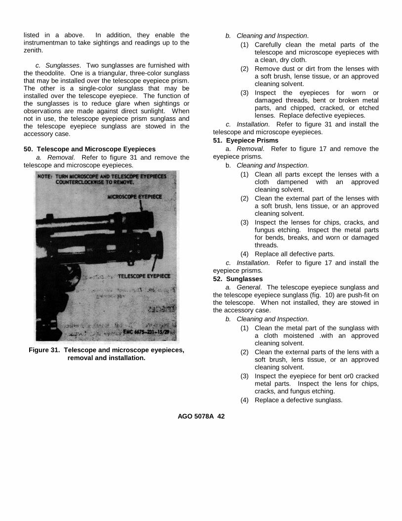
50. Telescope and Microscope Eyepiecesa. Removal. Refer to figure 31 and remove the
telescope and microscope eyepieces.
Figure 31. Telescope and microscope eyepieces,removal and installation.
b. Cleaning and Inspection.(1) Carefully clean the metal parts of the
telescope and microscope eyepieces witha clean, dry cloth.
(2) Remove dust or dirt from the lenses witha soft brush, lense tissue, or an approvedcleaning solvent.
(3) Inspect the eyepieces for worn ordamaged threads, bent or broken metalparts, and chipped, cracked, or etchedlenses. Replace defective eyepieces.
c. Installation. Refer to figure 31 and install thetelescope and microscope eyepieces.51. Eyepiece Prisms
a. Removal. Refer to figure 17 and remove theeyepiece prisms.
b. Cleaning and Inspection.(1) Clean all parts except the lenses with a
cloth dampened with an approvedcleaning solvent.
(2) Clean the external part of the lenses witha soft brush, lens tissue, or an approvedcleaning solvent.
(3) Inspect the lenses for chips, cracks, andfungus etching. Inspect the metal partsfor bends, breaks, and worn or damagedthreads.
(4) Replace all defective parts.c. Installation. Refer to figure 17 and install the
eyepiece prisms.52. Sunglasses
a. General. The telescope eyepiece sunglass andthe telescope eyepiece sunglass (fig. 10) are push-fit onthe telescope. When not installed, they are stowed inthe accessory case.
b. Cleaning and Inspection.(1) Clean the metal part of the sunglass with
a cloth moistened .with an approvedcleaning solvent.
(2) Clean the external parts of the lens with asoft brush, lens tissue, or an approvedcleaning solvent.
(3) Inspect the eyepiece for bent or0 crackedmetal parts. Inspect the lens for chips,cracks, and fungus etching.
(4) Replace a defective sunglass.
AGO 5078A 42

Section VIII. STAR PLATE53. General
The star plate enables the operator to quickly andaccurately secure the theodolite to, and remove it from,the tripod. This enables the operator to quickly movethe instrument from one station to another when closinga traverse, or making measurements where speed andextreme accuracy are required.54. Star Plate
a. Removal. Refer to figure 32 and remove thestar plate.
b. Cleaning and Inspection.(1) Clean all metal parts with an approved
cleaning solvent and dry thoroughly.Clean the footscrews with a soft brushdipped in an approved cleaning solvent.
(2) Inspect the star plate for burs, cracks,breaks, or other defects.
(3) Correct all -deficiencies or report them tofield maintenance.
c. Installation. Refer to figure 32 and install thestar plate.
Figure 32. Star plate, removal and installation.
Section IX. ILLUMINATION MIRRORS55. General
The horizontal circle illumination mirror and thevertical circle illumination mirror are identicalassemblies used to reflect light inside the theodolite toilluminate the vertical and horizontal circles.56. Illumination Mirrors
a. Removal. Refer to figure 33 and remove theillumination mirrors.
b. Cleaning and Inspection.(1) Clean all metal parts with an
approved cleaning solvent and drythoroughly. Clean the mirror with acamel's-hair brush, if dusty; cleanwith a chamois, if foggy.
(2) Inspect the hinge action for stiff orloose movement. Oil sparingly, ifnecessary, and wipe off all excessoil.
(3) Inspect for a cracked or brokenmirror. Inspect the metal mount forbends, cracks, and breaks.
(4) Replace a damaged or defectivemirror assembly.
c. Installation. Refer to figure 33 and install theillumination mirrors.
Figure 33. Illumination mirrors, removal andinstallation.
AGO 5078A 43

Section X. TRIPOD ASSEMBLY, PLUMB BOB, AND TRIPOD WRENCH57. GeneralThe tripod assembly is of the rigid-leg type whichconsists of the tripod head, tripod leg assemblies, andthe cover plate. When the theodolite is being used forsurveying work and other precision measuring, it ismounted on the tripod head. The plumb bob and tripodwrench are kept in the tripod tool kit mounted on one ofthe tripod legs. When the plumb bob is installed on thetripod, it is possible to center the
instrument exactly over the station point. The tripodwrench is used to tighten or loosen the clamping screwsunder the tripod head to hold the tripod legs in position.58. Tripod Assembly
a. Disassembly.(1) Remove the tripod tool kit (fig. 15).(2) Refer to figure 34 and disassemble the
tripod assembly.
1 Leg (6 rqr) 16 Setscrew2 Strap 17 Screw3 Washer (2 rqr) 18 Screw4 Screw (2 rqr) 19 Nut5 Bracket 20 Screw (6 rqr)6 Screw (4 rqr) 21 Bushing (3 rqr)7 Bracket 22 Screw (6 rqr)8 Screw (6 rqr) 23 Wedge (6 rqr)9 Housing 24 Screw (3 rqr)10 Pin (3 rqr) 25 Shoe (3 rqr)11 Screw (3 rqr) 26 Bushing (3 rqr)12 Head 27 Spacer (3 rqr)13 Cover 28 Spacer (3 rqr)14 Washer 29 Nut (3 rqr)15 Bridge screw
Figure 34. Tripod assembly, disassembly and reassembly.
AGO 5078A 44
b. Cleaning and Inspection.(1) Clean all metal parts with an approved
cleaning solvent and dry thoroughly.Clean the wood parts with a soft clothmoistened with water and dry thoroughly.Clean the strap with a suitable cleaner.
(2) Inspect the tripod leg housings and coverfor burs, cracks, and wear. Inspect thehead and cover for burs, scratches,cracks, and breaks. Inspect the bridge forbends, burs, wear, and damage. Inspectthe clamps, shoes, and battery boxbracket for cracks, breaks, and wear.
(3) Inspect the strap for cuts, wear, anddamage. Inspect the wood legs forcracks, splits, wear, and warping.
(4) Remove all burs and minor scratches.Straighten minor dents and bends.Varnish the wood legs if the protectivecoating is worn or damaged.
(5) Replace all defective parts that cannot berepaired.
c. Reassembly.(1) Refer to figure 34 and reassemble the
tripod assembly.(2) Install the tripod tool kit (fig. 15).
59. Plumb Bob and Tripod Wrencha. Plumb Bob.
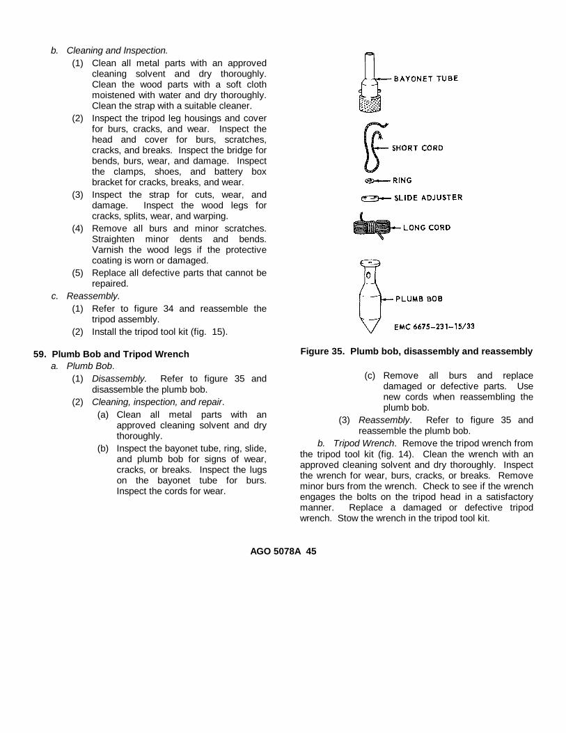
(1) Disassembly. Refer to figure 35 anddisassemble the plumb bob.
(2) Cleaning, inspection, and repair.(a) Clean all metal parts with an
approved cleaning solvent and drythoroughly.
(b) Inspect the bayonet tube, ring, slide,and plumb bob for signs of wear,cracks, or breaks. Inspect the lugson the bayonet tube for burs.Inspect the cords for wear.
Figure 35. Plumb bob, disassembly and reassembly
(c) Remove all burs and replacedamaged or defective parts. Usenew cords when reassembling theplumb bob.
(3) Reassembly. Refer to figure 35 andreassemble the plumb bob.
b. Tripod Wrench. Remove the tripod wrench fromthe tripod tool kit (fig. 14). Clean the wrench with anapproved cleaning solvent and dry thoroughly. Inspectthe wrench for wear, burs, cracks, or breaks. Removeminor burs from the wrench. Check to see if the wrenchengages the bolts on the tripod head in a satisfactorymanner. Replace a damaged or defective tripodwrench. Stow the wrench in the tripod tool kit.
AGO 5078A 45

CHAPTER 4DEMOLITION OF THEODOLITE TO PREVENT ENEMY USE
60. GeneralWhen capture or abandonment of the theodolite to
an enemy is imminent, the responsible unit commandermust make the decision either to destroy the equipmentor to render it inoperative. Based on this decision,orders are issued which cover the desired extent ofdestruction. Whatever method of demolition isemployed, it is essential to destroy the same vital partsof all theodolites and all corresponding repair parts.61. Demolition To Render the TheodoliteInoperative
a. Demolition by Mechanical Means. Using ahammer, bar, or other suitable tool, break all lenses,level vials, telescope, microscope, U-standard, tripodbase, ground plate, and metal hood. Destroy the tripod,battery box, and accessory case. Rip the field packapart.
b. Demolition by Burning. Pack oil-soaked rags,canvas, or other flammable material around thetheodolite, leveling base, ground plate, metal hood,tripod, battery box, field pack, and accessory case and
set fire to the pile. Be sure the burning is thorough andcomplete before leaving.
c. Demolition by Submersion. Remove thetheodolite from the carrying case. Submerge theinstrument and all of its accessories in a body of waterto insure water damage and provide concealment. Saltwater will do the greatest damage to the metal parts.62. Training
All operators should receive thorough training in thedestruction of the theodolite. Simulated destruction,using all of the methods listed above, should beincluded in the operator training program. It must beemphasized in training that demolition operations areusually necessitated by critical situations when timeavailable for carrying out destruction is limited. For thisreason, it is necessary that operators be thoroughlyfamiliar with all methods of destruction of equipment,and be able to carry out demolition instructions withoutreference to this or any other manual.
AGO 5078A 46
CHAPTER 5SHIPMENT AND LIMITED STORAGE
Section I. SHIPMENT WITHIN ZONE OF INTERIOR
63. Preparation of Theodolite for Shipmenta. General. Detailed instructions for the
preparation of Engineer equipment for domesticshipment are outlined within this paragraph.
b. Inspection. Perform a complete inspection asoutlined in paragraph 8.
c. Cleaning and Drying. Remove dust and dirtfrom the theodolite a id dry thoroughly. Refer to TM 38-230 for selection and application of cleaning and dryingmethods. EXCEPTION: clean all lenses and externalprisms, using the camel's-hair brush provided with theequipment.
d. Painting. Paint all surfaces where the paint hasbeen removed or damaged. Refer to TB ENG 60 fordetailed cleaning and painting instructions.
e. Lubrication. Refer to paragraphs 26, 27, and 28for selection and application of lubricants and areas tobe lubricated.
f. Exterior Surfaces. When the instrument is to beplaced in its carrying case and shipping case, it is notnecessary to coat the machined ferrous metal surfaceswith preservative. If the cases have become damagedor are not available, immediately after cleaning,exposed threads and unpainted machined ferrous metalsurfaces of parts and accessories will be coated withlubricants specifically approved for use on theinstrument.
g. Marking. Marking will conform Lo MILSTD-129and fragile labels (DA LABEL 3, 4, or 5) will be affixedto at least three surfaces of the theodolite shipping case.
h. Batteries and Cables. Batteries will be removedfrom the battery box and packed in a suitable container.Cables will be disconnected, holes and openings sealed,and all terminals and connections wrapped and securedwith type II, class 1, pressure-sensitive tape conformingto Specification PPP-T-60.
i. Disassembly and Packing.(1) Disassemble and pack the accessories
(reverse the instructions in paragraphs 7bthrough e) in the accessory container.
(2) Refer to paragraph 47c and inspect thedesiccant. Replace desiccant ifnecessary. Reverse the instructions inparagraph 7a and pack the theodolite inthe carrying case.
NoteRefer to TM 38-230 for guidance inselecting, fabricating, and packing asuitable accessory container.
64. Loading the Theodolite for Shipmenta. Loading. Loading the instrument for shipment
can be accomplished by one man.b. Shipping. Air transport is the best means of
shipping the theodolite, as such travel subjects theinstrument to a minimum of vibration, jolts, and stresscaused by abrupt starts and stops. The shipping casesshould be tied down securely and provision madeagainst the possibility of the instrument shipping casebeing struck by loose objects or shifting freight.
Section II. LIMITED STORAGE
65. Preparation of Theodolite for Storagea. General. Prepare the theodolite for limited
storage in the same manner as outlined in
paragraph 63. Limited storage is defined as storage notto exceed 6 months. Refer to AR 743-505.
AGO 5078A 47

b. Storage. Store the theodolite, tripod, andaccessories; in a dry, dust-free location where there is aminimum of vibration.
66. Inspection and Maintenance of Theodolite inStorageFrequent inspection must be made to assure theequipment is ready for immediate use. Frequency ofinspections will be prescribed by the
unit commander, taking into consideration such factorsas the physical condition of the storage area,weatherproofing, vibrations, security from tampering orpilferage, humidity, and temperature conditions. Thetripod and accessories must be inspected frequentlyunless they are in hermetically sealed packagescontaining adequate desiccants.
AGO 5078A 48
CHAPTER 6FIELD AND DEPOT MAINTENANCE INSTRUCTIONS
Section I. GENERAL67. Scope
a. The following instructions are for field and depotmaintenance personnel. They contain information onequipment maintenance that is beyond the scope of thetools, equipment, personnel, or supplies normallyavailable to organizational maintenance.
b. Appendix I includes the publications applicable tofield and depot maintenance. Appendix II contains themaintenance allocation chart. The field and depotmaintenance repair parts and special tool lists are listedin TM 5-6675-231-25P.
68. Record and Report FormsFor record and report forms applicable to field and depotmaintenance, refer to TM 38 750.
NoteApplicable forms, excludingStandard Form46 which is carried bythe operator, shall be kept in acanvas bag mounted on theequipment.
Section II. DESCRIPTION AND DATA69. DescriptionFor a complete description of the theodolite, seeparagraph 3.70. Tabulated Data
a. General. This paragraph contains overhaul datapertinent to field and depot maintenance personnel.
b. Time Standards. Table II lists the number ofman-hours required under normal conditions to performthe indicated maintenance and repair for the theodolite.Components are listed under the appropriate functionalindex. The times listed are not intended to be rigidstandards. Under adverse conditions, the operations willtake longer; but under ideal conditions with highly skilledinstrument repairmen, most of the operations can beaccomplished in considerably less time.
Table II. Time StandardsHours
(1) Lubrication and Service67 PRECISION INSTRUMENTS
6700 THEODOLITETheodolite
Clean (general)(Use soft cloth free fromdirt and oil, only on ex-
Table II. Time Stands-ContinuedHours
terior parts, not to in-clude lens and mirrors.Do not use water, oil, orliquids when cleaning)... 0.3
Clean (special)(Use lens cloth to cleanmirrors and lens. Usesaddle soap on tripod ac-cessory case when leatherbecomes hard or dry. Uselinseed oil on tripod legs.Use a very stiff brushwhen cleaning canvas ac-cessory case.) .............. 0.4
(2) Remove and Replace17 HOOD
1708 CARRYING CASESCase assembly, carrying ..... 0.1Pack rack ........................... 0.1Case, shipping: Theodolite.. 0.1
26 ACCESSORIES, PUBLICATIONS,TEST EQUIPMENT AND TOOLS
2602 ACCESSORIESCase, accessory ................. 0.2Socket assembly, plumb bob... 0.1Cover, plastic ..................... 0.1Kit, tool: tripod .................... 0.1
2604 SPECIAL TOOLSWrench, tripod ................... 0.1
AGO 5078A49

Table II. Time Standards-ContinuedHours
67 PRECISION INSTRUMENTS6700 THEODOLITE
Theodolite(includes adjustment) ............... 1.3
6701 TELESCOPE ASSEMBLYAxis, telescope
(includes removal and in-stallation of reticle mirror,vertical clamp, and tele-scope tube.) ....................... 6.0
Tube, telescope(includes removal and in-stallation of eyepiece as-sembly and objective as-sembly)............................... 2.7
Bearing, right side(includes removal and in-stallation of micrometerassembly) ........................... 1.2
Bearing, left side(includes removal and in-stallation of vertical circle) .. 3.0
6702 OPTICSObjective assembly, telescope ........ 0.7Lens assembly, focus
(includes removal and in-stallation of the reticle as-sembly) ............................... 1.4
Reticle assembly, telescope(includes removal and in-stallation of microscope,and telescope eyepieces) .......... 0.8
Eyepiece assembly, telescope,(includes removal and in-stallation of microscope) ........... 1.5
Eyepiece, telescope ........................ 0.2Microscope assembly ...................... 0.3Objective assembly, micro-
scope ............................... 0.6Eyepiece, prisms, microscope
and telescope............................ 0.1Eyepiece, microscope ..................... 0.2Mirror assembly, illumination ........... 0.1Prisms, micrometer and ver-
tical circle ............................... 3.2Mirror assembly, reticle ................... 0.8Lens assembly, vertical circle(includes removal and installationof left side bearing).......................... 4.0Circle, horizontal
(includes removal and in-stallation of U-standard) ............ 6.8
Vertical circle assembly(includes removal and in-stallation of left side bear-ing) ............................... 3.0
Table II. Time Standards-ContinuedHours
Circle, micrometer .................... 2.0Sunglass, telescope eyepiece ... 0.1Micrometer assembly ................ 0.4Gunsight (front) ......................... 0.4Cap, dust, telescope.................. 0.1
6703 MECHANICAL, STRUCTURAL,AND PRECISION PARTS
Clamp assembly, vertical(includes removal and in-stallation of right sidetelescope axis bearing) ....... 1.6
Star plate ............................... 0.3U-standard assembly
(includes removal and in-stallation of horizontalcircle prism housing) ........... 6.0
Screw, leveling(includes adjustment andremoval and installation ofstar plate)............................ 1.2
Clamp assembly, horizontal(includes removal and in-stallation of horizontalslow-motion screw) ............ 0.8
Screw assemblies, slow-motion(includes adjustment).......... 1.1
Base, housing assembly(includes removal and in-stallation of the horizontalcircle and circle drive)......... 8.0
Circle drive assembly, hori-zontal(includes adjustment).......... 0.8
Housing, prism, horizontalcircle(includes removal and in-stallation of base housingcover and leveling screws).. 3.2
6708 BATTERIESBattery, dry cell ......................... 0.2
6709 LAMPSFitting, lamp ............................. 0.1Lamp (bulb) .............................. 0.1Light, hand 0.1
6718 MOUNTED CONNECTINGDEVICES
Socket, illumination ............ 0.4Contact ring(includes removal and in-stallation of U-standard) ...... 6.8
6719 MISCELLANEOUS WIRINGAND FITTINGS
Cable, electrical (internal)(includes removal and in-stallation of horizontalcircle) ............................... 7.2
AGO 6018A50
Table II. Time Standards-ContinuedHours
6723 POWER SUPPLYBattery box assembly .......................... 0.2Cable, electrical................................... 0.1
6724 LEVELSPlate level assembly............................ 0.7Collimation level assembly .................. 1.2Collimation lever assembly .................. 1.2
Table II. Time Standards-ContinuedHours
6725 TRIPODSTripod ................................... 0.2Head assembly, tripod........... 0.5Leg assembly, tripod ............. 0.5Cover, tripod ........................ 0.1
82 MINERALS AND CHEMICALSContainer, desiccant 0.2
Section III. SPECIAL TOOLS AND EQUIPMENT
71. Special Tools and Equipment
No special tools or equipment are required by fieldand depot maintenance personnel for performingmaintenance on the theodolite.
72. Field and Depot Maintenance Repair Parts
Field and depot maintenance repair parts are listedand illustrated in TM 5-6675-231-25P.
73. Specially Designed Tools and Equipment
The specially designed tools and equipment illustratedin figure 36 and listed in table III are for field and depotmaintenance personnel performing major overhaul workon the theodolite. The tools and equipment listed intable III are not available for issue, but must befabricated by qualified field and depot maintenancepersonnel.
Table III. Specially Designed Tools
ReferencesItem Figure Paragraph Use
Puller, horizontal circle............... 36A 115 To remove and install the horizontal circle.Tool, rotating prism mount ......... 36B 111 To remove and install the horizontal circle prism carrier.Wrench, tripod base................... 36C 54 To remove and install the star plate nut.Tool, adjusting and assembly .... 36D 104 To hold reticle mirror axis in position.Tool, adjusting and assembly..... 36E 102-103 To remove and install the eyepiece lens lockring.Wrench, adjustable spanner....... 36F 108 To remove and install slow-motion screw spring housings.
51 AGO 5078A
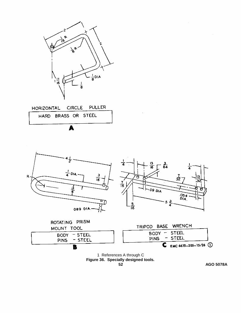
1 References A through CFigure 36. Specially designed tools.
52 AGO 5078A
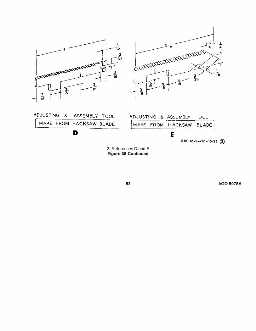
2 References D and EFigure 36-Continued
53 AGO 5078A
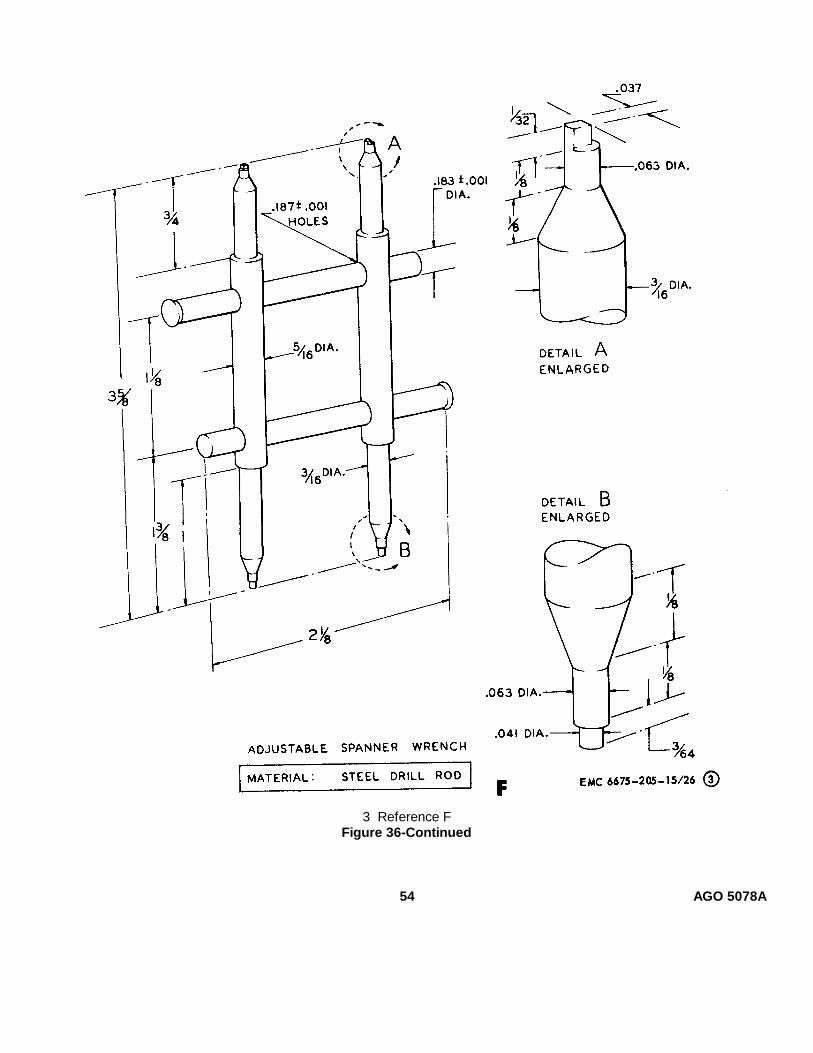
3 Reference FFigure 36-Continued
54 AGO 5078A

Section IV. TROUBLESHOOTING
74. GeneralThis section provides information useful in
diagnosing and correcting unsatisfactory operation orfailure of the theodolite and its components. Eachtrouble symptom stated is followed by a list of probablecauses of trouble. The possible remedy recommendedis described opposite the probable cause.75. Theodolite Will Not Seat Properly on TripodHeadProbable cause Possible remedyStar plate defective .............. Replace or repair the star
plate (par. 95).76. Theodolite Will Not Stay on LineProbable cause Possible remedyVertical travel off line ........... Line up right side axis
bearing (par. 122).Excessive right side axis Aline or replace axis bear-
bearing side play. ing (par. 122).Star plate loose or defec- Tighten, replace, or repair
tive. star plate (par. 95).77. Leveling Screws Too Tight or Too LooseProbable cause Possible remedyLeveling screws dirty or Clean, repair, or replace
worn. leveling screws (par.117).
Leveling screws out of Adjust leveling screwsadjustment. (par. 117).
78. Telescope Turns Too Hard or Too EasilyProbable cause Possible remedyRight side axis bearing Replace axis bearing (par.
defective. 122).Telescope axis worn............. Replace axis (par. 123).79. Horizontal Circle Hard To MoveProbable cause Possible remedyHorizontal circle drive de- Repair, replace, or adjust
fective or out of adjust- circle drive (par. 118).ment.
Circle drive teeth dirty or Clean, repair, or replaceworn. circle drive teeth (pars.
115 and 118).80. Plate Level Vial DefectiveProbable cause Possible remedyDefective bubble ................. Replace vial (par. 97).Level vial broken ................. Replace vial (par. 97).
81. Plate Level Bubble Does Not Stay in CenterProbable cause Possible remedyLeveling screws loose or Adjust or replace screws
worn. (par. 117).Plate level bubble jumps ...... Replace level vial (par. 97).82. Collimation Level Bubble Does Not Stay in CenterProbable cause Possible remedyLevel mounting loose .......... Tighten screws (par. 93).Level bearing binds ............. Clean bearing (par. 93).Level bubble jumps ............. Replace level vial (par. 93).83. Illumination System Fails To FunctionProbable cause Possible remedyWiring defective Repair or replace wiring
(pars. 128 and 129).Faulty contact between Clean ring or clean and
U-standard contact and straighten points (par.contact ring due to bent 115).or dirty points and ring.
Illumination socket defec- Replace socket (par. 119).tive.
Battery box rheostat de- Replace rheostat (par. 128).fective.
Battery box defective .......... Repair or replace batterybox (par. 128).
84. Horizontal Circle Has Unequal Light or No LightProbable cause Possible remedyIllumination system de- Refer to paragraph 83.
fective.Illumination prism dirty, Clean, tighten, or replace
fogged, etched, or loose. prism (par. 110).85. Vertical Circle Has Unequal Light or No LightProbable cause Possible remedyIllumination system de- Refer to paragraph 83.
fective.Inverter prism dirty, Clean, tighten, or replace
loose, or etched. prism (par. 100).86. Horizontal Circle Graduations UnequalProbable cause Possible remedyIllumination prism im- Reinstall or replace prism
properly installed or (par. 110).defective.
87. Horizontal Circle Graduations Not at RightAngles to Line Dividing the Two ImagesProbable cause Possible remedyHorizontal circle prism Adjust horizontal prism
carrier too loose or carrier (par. 111).too tight.
55 AGO 5078A

88. Vertical Circle Images Have Moved in Relationto the Line Dividing the Two Images and to theReference Mark
Probable cause Possible remedyVertical circle prism im Reinstall or replace prism
properly installed or (par. 98).defective.
89. Micrometer Circle Has Unequal Light or NoLight
Probable cause Possible remedyMicrometer circle prism Clean or replace prism
dirty or defective. (par. 99).Defect in illumination Refer to paragraph 83.
system.
Section V. ILLUMINATION MIRRORS
90. GeneralTwo identical illumination mirrors are supplied with
the theodolite. The vertical circle illumination mirrormounts on the vertical circle collar and the horizontalcircle illumination mirror mounts on the socket on thehorizontal base. The mirrors illuminate the vertical,horizontal, and micrometer circles.91. Illumination Mirrors
a. Removal. Refer to paragraph 56 and removethe illumination mirrors.
b. Disassembly. Refer to figure 37 anddisassemble the. illumination mirrors.
c. Cleaning, Inspection, and Repair.(1) Clean all metal parts with an approved
cleaning solvent and dry thoroughly.
Clean the mirror with an approvedcleaning solvent and polish it with lenstissue or a lens cloth.
(2) Inspect the mirror for cracks, breaks, andloose backing.
(3) Inspect the sleeve and mount for bends,cracks, and burs. Inspect the pins forburs, bends, and wear.
(4) Remove minor burs and straighten allslightly bent parts. Replace a damagedmirror. Cement the mirror firmly in placeand let it dry thoroughly. Remove allexcess adhesive.
d. Reassembly. Refer to figure 37 and reassemblethe illumination mirrors.
e. Installation. Refer to paragraph 56 and installthe illumination mirrors.
Figure 37. Illumination mirrors, disassembly and reassembly.
56 AGO 5078A
Section VI. COLLIMATION LEVEL AND LEVER ASSEMBLY
92. GeneralThe collimation level and lever assembly is
provided to enable the operator to establish an exacthorizontal plane and to make precise measurementsrelative to that plane.93. Collimation Level and Lever Assembly
a. Removal.(1) Remove the illumination mirror (par. 56).(2) Refer to figure 38 and remove the
collimation level and lever assembly.b. Disassembly. Refer to figure 39 and
disassemble the collimation level and lever assembly.c. Cleaning, Inspection, and Repair.
(1) Clean all metal parts with an approvedcleaning solvent and dry thoroughly.Brush out all threaded surfaces with abrush dipped in an approved cleaningsolvent. Polish the prism with lens tissueor with a lens cloth.
(2) Inspect all threaded surfaces for worn ordamaged threads. Inspect the prisms forchips, scratches, and etchings. Inspectthe collimation lever, prism housing,carrier, level vial housing, cover, levelcover, and sleeve for cracks, bends,dents, burs, and wear.
(3) Remove all burs and straighten all dentsand bends. Replace defective parts thatcannot be repaired.
d. Reassembly. Refer to figure 39 and reassemblethe collimation level and lever assembly.
e. Installation.(1) Refer to figure 38 and install the
collimation level and lever assembly.(2) Install the illumination mirror (par. 56).
f. Adjustment. Refer to figure 24 and adjust thecollimation level.
57 AGO 5078A
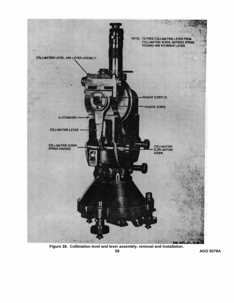
Figure 38. Collimation level and lever assembly, removal and installation.58 AGO 5078A

Figure 39. Collimation level assembly, disassembly and reassembly.
59 AGO 5078A
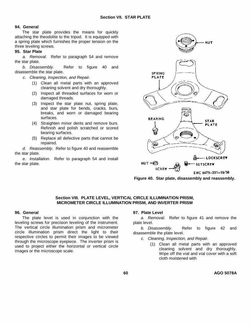
Section VII. STAR PLATE
94. GeneralThe star plate provides the means for quickly
attaching the theodolite to the tripod. It is equipped witha spring plate which furnishes the proper tension on thethree leveling screws.95. Star Plate
a. Removal. Refer to paragraph 54 and removethe star plate.
b. Disassembly. Refer to figure 40 anddisassemble the star plate.
c. Cleaning, Inspection, and Repair.(1) Clean all metal parts with an approved
cleaning solvent and dry thoroughly.(2) Inspect all threaded surfaces for worn or
damaged threads.(3) Inspect the star plate nut, spring plate,
and star plate for bends, cracks, burs,breaks, and worn or damaged bearingsurfaces.
(4) Straighten minor dents and remove burs.Refinish and polish scratched or scoredbearing surfaces.
(5) Replace all defective parts that cannot berepaired.
d. Reassembly. Refer to figure 40 and reassemblethe star plate.
e. Installation. Refer to paragraph 54 and installthe star plate.
Figure 40. Star plate, disassembly and reassembly.
Section VIII. PLATE LEVEL, VERTICAL CIRCLE ILLUMINATION PRISM,MICROMETER CIRCLE ILLUMINATION PRISM, AND INVERTER PRISM
96. GeneralThe plate level is used in conjunction with the
leveling screws for precision leveling of the instrument.The vertical circle illumination prism and micrometercircle illumination prism direct the light to theirrespective circles to permit their images to be viewedthrough the microscope eyepiece. The inverter prism isused to project either the horizontal or vertical circleimages or the microscope scale.
97. Plate Levela. Removal. Refer to figure 41 and remove the
plate level.b. Disassembly. Refer to figure 42 and
disassemble the plate level.c. Cleaning, Inspection, and Repair.
(1) Clean all metal parts with an approvedcleaning solvent and dry thoroughly.Wipe off the vial and vial cover with a softcloth moistened with
60 AGO 5078A
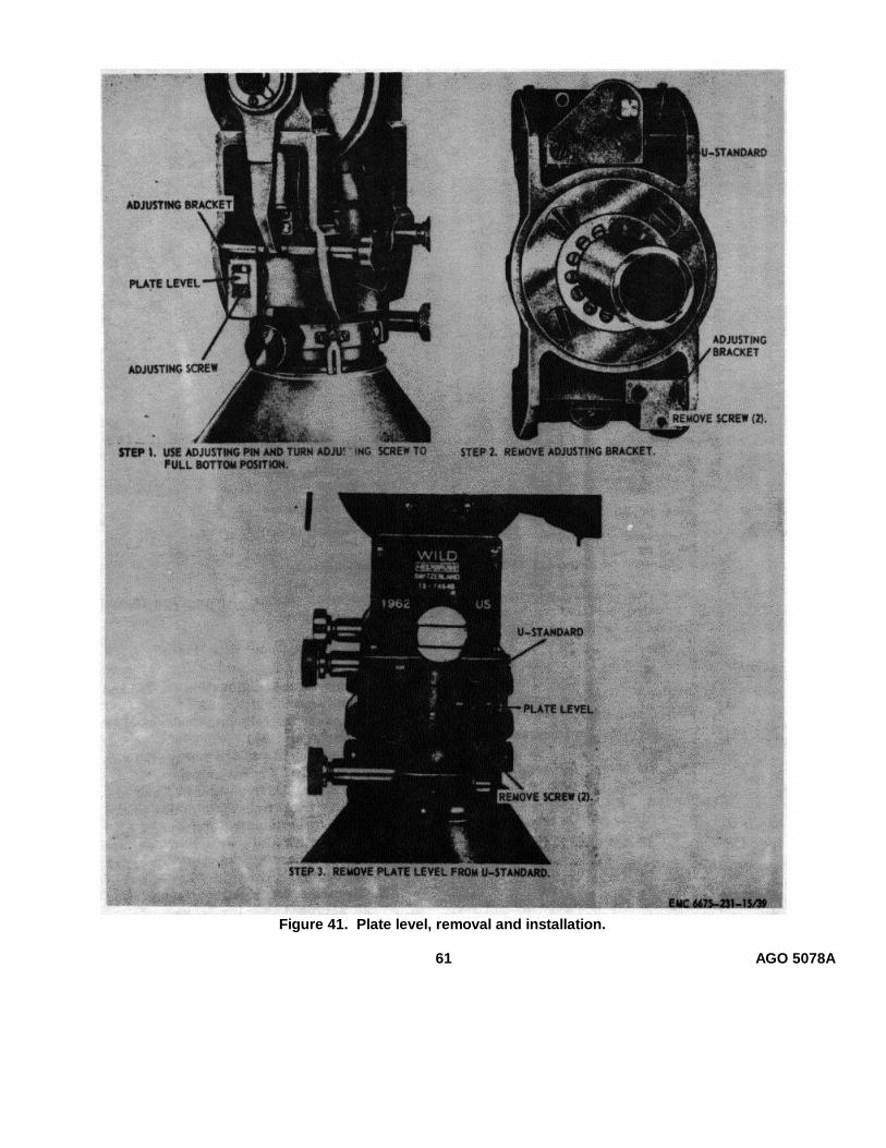
Figure 41. Plate level, removal and installation.
61 AGO 5078A

Figure 42. Plate level, disassembly and reassembly.
an approved cleaning solvent. Clean allthreaded surfaces with a brush dipped inan approved cleaning solvent.
(2) Inspect the vial for cracks, etchings, anddefective bubble. Inspect the plastic vialcover for cracks, splits, scratches, andwear.
(3) Inspect the brackets for cracks, burs, andbreaks.
(4) Inspect the spring for wear and fatigue.Inspect the plunger for burs and wear.Inspect the screws for worn or damagedthreads. Inspect the housing for cracks orother defects.
(5) Remove all burs and replace all defectiveparts.
d. Reassembly. Refer to figure 42 and reassemblethe plate level.
e. Installation. Refer to figure 41 and install theplate level.
f. Adjustment. Refer to paragraph 16 and adjustthe plate level.98. Vertical Circle Illumination Prism
a. Removal.(1) Remove the collimation level and lever
assembly (par. 93).(2) Remove the collimation slow-motion
screw (par. 108).(3) Refer to figure 43 and remove the vertical
circle illumination prism.b. Disassembly. Refer to figure 44 and
disassemble the vertical circle illumination prism.c. Cleaning, Inspection, and Repair.
(1) Clean all metal parts with an approvedcleaning solvent and dry thoroughly.
(2) Clean the prism with lens tissue or anapproved cleaning solvent.
(3) Inspect the prism for chips, cracks,scratches, and etching.
(4) Replace damaged or defective parts.
62 AGO5078A

Figure 43. Vertical circle illumination prism,removal and installation.
d. Reassembly. Refer to figure 44 and reassemblethe vertical circle illumination prism.
e. Installation.(1) Refer to figure 43 and install the vertical
circle illumination prism assembly.(2) Install the collimation slow-motion screw
(par. 108).(3) Refer to paragraph 93 and install the
collimation level and lever assembly.99. Micrometer Circle Illumination Prism
a. Removal. Refer to figure 45 and remove themicrometer circle illumination prism.
b. Disassembly. Refer to figure 46 anddisassemble the micrometer circle illumination prism.
c. Cleaning, Inspection, and Repair.(1) Clean all metal parts with an approved
cleaning solvent and dry thoroughly.(2) Clean the glass prism with lens tissue or a
lens cloth.(3) Inspect the prism for chips, cracks,
scratches, and etching.
Figure 44. Vertical circle illumination prism, disassembly and reassembly.
63 AGO 5078A
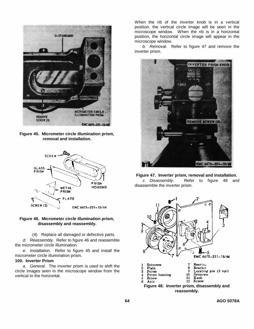
Figure 45. Micrometer circle illumination prism,removal and installation.
Figure 46. Micrometer circle illumination prism,disassembly and reassembly.
(4) Replace all damaged or defective parts.d. Reassembly. Refer to figure 46 and reassemble
the micrometer circle illumination.e. Installation. Refer to figure 45 and install the
micrometer circle illumination prism.100. Inverter Prism
a. General. The inverter prism is used to shift thecircle images seen in the microscope window from thevertical to the horizontal.
When the rib of the inverter knob is in a verticalposition, the vertical circle image will be seen in themicroscope window. When the rib is in a horizontalposition, the horizontal circle image will appear in themicroscope window.
b. Removal. Refer to figure 47 and remove theinverter prism.
Figure 47. Inverter prism, removal and installation.c. Disassembly. Refer to figure 48 and
disassemble the inverter prism.
Figure 48. Inverter prism, disassembly andreassembly.
64 AGO 5078A

d. Cleaning, Inspection, and Repair.(1) Clean all metal parts with an approved
cleaning solvent and dry thoroughly.Carefully clean the inverter prism with alens cloth or with lens tissue.
(2) Inspect the plate, bracket, and housing forburs, dents, bends, cracks, and otherdamage. Inspect the bearing and axis forburs, scratches, cracks, and wear.
(3) Inspect the inverter prism for chips,scratches, cracks, and etching.
(4) Straighten minor dents and bends.Remove all burs.
(5) Replace all damaged or defective parts.e. Reassembly. Refer to figure 48 and reassemble
the inverter prism.f. Installation. Refer to figure 47 and install the
inverter prism.
Section IX. MICROSCOPE, TELESCOPE, AND RETICLE MIRROR
101. GeneralThe microscope is used to bring the horizontal,
vertical, and micrometer circle scales into proper focus.The microscope eyepiece is knurled to assist theoperator in making this adjustment. The telescopeprovides a means of .sighting and bringing into focusthe objective or target. The eyepiece is used to bringthe reticle crosslines into view. The focusing tube isused to bring the objective into focus. The reticlemirror, located in the telescope tube, is provided toilluminate the reticle crosslines when the electricalillumination system is utilized.
102. Microscopea. Removal. Refer to figure 49 and remove the
microscope.b. Disassembly.
(1) Remove the microscope eyepiece (par.50).
(2) Refer to figure 50 and disassemble themicroscope.
Figure 49. Microscope and telescope eyepiece end,removal and installation.
Figure 50. Microscope, disassembly and reassembly.
65 AGO 5078A
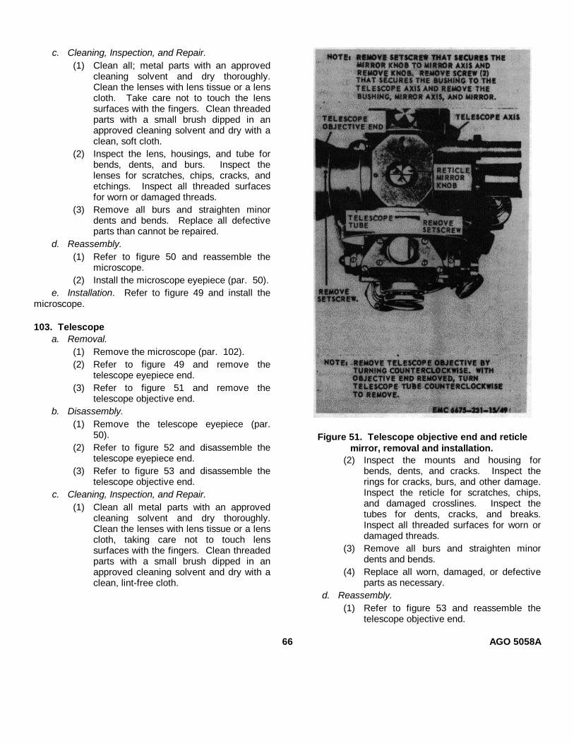
c. Cleaning, Inspection, and Repair.(1) Clean all; metal parts with an approved
cleaning solvent and dry thoroughly.Clean the lenses with lens tissue or a lenscloth. Take care not to touch the lenssurfaces with the fingers. Clean threadedparts with a small brush dipped in anapproved cleaning solvent and dry with aclean, soft cloth.
(2) Inspect the lens, housings, and tube forbends, dents, and burs. Inspect thelenses for scratches, chips, cracks, andetchings. Inspect all threaded surfacesfor worn or damaged threads.
(3) Remove all burs and straighten minordents and bends. Replace all defectiveparts than cannot be repaired.
d. Reassembly.(1) Refer to figure 50 and reassemble the
microscope.(2) Install the microscope eyepiece (par. 50).
e. Installation. Refer to figure 49 and install themicroscope.
103. Telescopea. Removal.
(1) Remove the microscope (par. 102).(2) Refer to figure 49 and remove the
telescope eyepiece end.(3) Refer to figure 51 and remove the
telescope objective end.b. Disassembly.
(1) Remove the telescope eyepiece (par.50).
(2) Refer to figure 52 and disassemble thetelescope eyepiece end.
(3) Refer to figure 53 and disassemble thetelescope objective end.
c. Cleaning, Inspection, and Repair.(1) Clean all metal parts with an approved
cleaning solvent and dry thoroughly.Clean the lenses with lens tissue or a lenscloth, taking care not to touch lenssurfaces with the fingers. Clean threadedparts with a small brush dipped in anapproved cleaning solvent and dry with aclean, lint-free cloth.
Figure 51. Telescope objective end and reticlemirror, removal and installation.
(2) Inspect the mounts and housing forbends, dents, and cracks. Inspect therings for cracks, burs, and other damage.Inspect the reticle for scratches, chips,and damaged crosslines. Inspect thetubes for dents, cracks, and breaks.Inspect all threaded surfaces for worn ordamaged threads.
(3) Remove all burs and straighten minordents and bends.
(4) Replace all worn, damaged, or defectiveparts as necessary.
d. Reassembly.(1) Refer to figure 53 and reassemble the
telescope objective end.
66 AGO 5058A
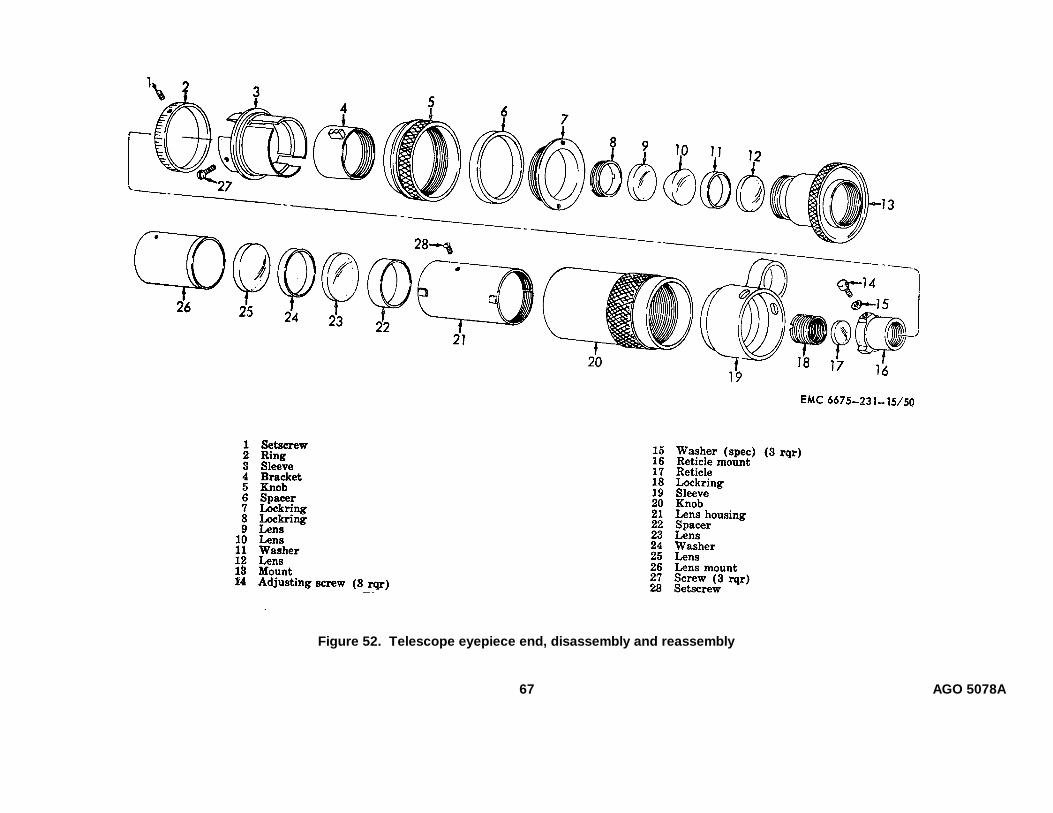
Figure 52. Telescope eyepiece end, disassembly and reassembly
67 AGO 5078A
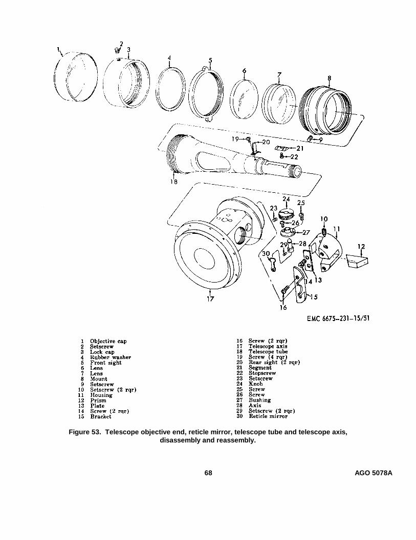
Figure 53. Telescope objective end, reticle mirror, telescope tube and telescope axis,disassembly and reassembly.
68 AGO 5078A
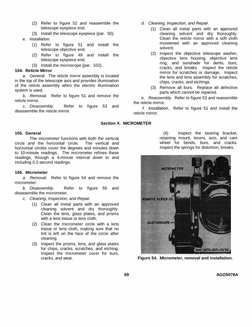
(2) Refer to figure 52 and reassemble thetelescope eyepiece end.
(3) Install the telescope eyepiece (par. 50).e. Installation.
(1) Refer to figure 51 and install thetelescope objective end.
(2) Refer to figure 49 and install thetelescope eyepiece end.
(3) Install the microscope (par. 102).104. Reticle Mirror
a. General. The reticle mirror assembly is locatedin the top of the telescope axis and provides illuminationof the reticle assembly when the electric illuminationsystem is used.
b. Removal. Refer to figure 51 and remove thereticle mirror.
c. Disassembly. Refer to figure 53 anddisassemble the reticle mirror.
d. Cleaning, Inspection, and Repair.(1) Clean all metal parts with an approved
cleaning solvent and dry thoroughly.Clean the reticle mirror with a soft clothmoistened with an approved cleaningsolvent.
(2) Inspect the objective telescope washer,objective lens housing, objective lensring, and sunshade for dents, burs,cracks, and breaks. Inspect the reticlemirror for scratches or damage. Inspectthe lens and lens assembly for scratches,chips, cracks, and etchings.
(3) Remove all burs. Replace all defectiveparts which cannot be repaired.
e. Reassembly. Refer to figure 53 and reassemblethe reticle mirror.
f. Installation. Refer to figure 51 and install thereticle mirror.
Section X. MICROMETER
105. GeneralThe micrometer functions with both the vertical
circle and the horizontal circle. The vertical andhorizontal circles cover the degrees and minutes downto 10-minute readings. The micrometer refines thesereadings, through a 4-minute interval down to andincluding 0.2-second readings.
106. Micrometera. Removal. Refer to figure 54 and remove the
micrometer.b. Disassembly. Refer to figure 55 and
disassemble the micrometer.c. Cleaning, Inspection, and Repair.
(1) Clean all metal parts with an approvedcleaning solvent and dry thoroughly.Clean the lens, glass plates, and prismswith a lens tissue or lens cloth.
(2) Clean the micrometer circle with a lenstissue or lens cloth, making sure that nolint is left on the face of the circle aftercleaning.
(3) Inspect the prisms, lens, and glass platesfor chips, cracks, scratches, and etching.Inspect the micrometer cover for burs,cracks, and wear.
(4) Inspect the bearing bracket,retaining mount, levers, axis, and camwheel for bends, burs, and cracks.Inspect the springs for distortion, breaks,
Figure 54. Micrometer, removal and installation.
69 AGO5078A
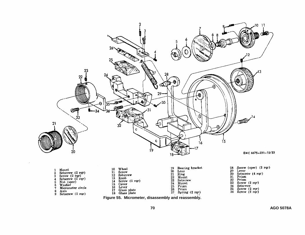
Figure 55. Micrometer, disassembly and reassembly.
70 AGO 5078A

and fatigue. Inspect all threaded surfacesfor worn or damaged threads.
(5) Remove all burs and straighten minordents and bends. Replace the springs ifthey are defective. Replace all worn or
damaged parts that cannot be repaired.d. Reassembly. Refer to figure 55 and reassemble
the micrometer.e. Installation. Refer to figure 54 and install the
micrometer.
Section XI. HORIZONTAL, VERTICAL, AND COLLIMATION SLOW-MOTION SCREWS
107. GeneralThe horizontal slow-motion screw is mounted on
the horizontal clamp and located on the right side of thetheodolite. It is used for precise pointing of theinstrument in a horizontal plane. The vertical slow-motion screw is located on the right side of thetheodolite. It is used to accurately point the instrumentin a vertical plane. The collimation slow-motion screw islocated on the left side of the theodolite and is used todetermine the horizontal line of sight by bringing the twoends of the collimation level bubble to coincidence.
108. Horizontal, Vertical, and Collimation Slow-Motion Screws
a. Removal. Refer to figure 56 and remove thehorizontal, vertical, and collimation slowmotion screws.
b. Disassembly. Refer to figure 57 anddisassemble the horizontal, vertical, and collimationslow-motion screws.
c. Cleaning, Inspection, and Repair.(1) Clean all parts with an approved cleaning
solvent and dry thoroughly. Clean allthreaded surfaces thoroughly with a smallbrush dipped in an approved cleaningsolvent. Remove all grease and foreignmatter from the inside of the housing andsleeves.
(2) Thoroughly clean the inside of theadjusting knobs, split nuts, stop nuts, andscrew housings.
(3) Inspect all threaded surfaces for worn ordamaged threads. Inspect the springs forwear, breaks, and fatigue. Inspect theadjusting knobs for burs and wear.
(4) Inspect the pins, housings, and adjustingscrews for wear, bends, burs, and otherdamage.
(5) Remove all burs. Replace all defectiveparts that cannot be repaired.
d. Reassembly. Refer to figure 57 and reassemblethe horizontal, vertical, and collimation slow-motionscrews.
e. Installation. Refer to figure 56 and install thehorizontal, vertical, and collimation slowmotion screws.
Figure 56. Horizontal, vertical, and collimationslow-motion screws, removal and installation.
71 AGO 5078A

Figure 57. Horizontal, vertical, and collimation slow-motion screws, disassembly and reassembly.
72 AGO 5078A

Section XII. HORIZONTAL CIRCLE ILLUMINATION PRISM AND HOUSING COVER,HORIZONTAL CIRCLE PRISM CARRIER, AND ILLUMINATION CABLE CONNECTOR
109. GeneralThe horizontal circle housing cover encloses the bottomof the horizontal circle housing and serves as a mountfor the horizontal circle illumination prism. Theillumination prism directs light to the horizontal circleprisms. The horizontal circle prisms transmit the circleimage to the microscope window and also provides lightfor reading the micrometer circle. The cable connectorprovides a means for connecting the electrical cablefrom the contact ring to the socket.
110. Horizontal Circle Housing Cover andHorizontal Circle Illumination Prism
a. Removal.(1) Remove the leveling screws (par. 117).(2) Refer to figure 58 and remove the
horizontal circle housing cover andhorizontal circle illumination prism.
Figure 58. Horizontal circle housing cover andhorizontal circle illumination prism, removal andinstallation.
b. Disassembly. Refer to figure 59 anddisassemble the horizontal circle housing cover andhorizontal circle illumination prism.
c. Cleaning, Inspection, and Repair.(1) Clean all metal parts with an approved
cleaning solvent and dry thoroughly.(2) Clean the prism and lens with a lens cloth
or lens tissue.(3) Inspect the horizontal circle housing cover
for dents, cracks, or other defects.Inspect all threaded parts for damaged orworn threads.
(4) Inspect the prism and lens for cracks,chips, etchings, and other damage.
(5) Replace all damaged or worn parts.d. Reassembly. Refer to figure 59 and reassemble
the horizontal circle housing cover and horizontal circleillumination prism.
e. Installation.(1) Refer to figure 58 and install the
horizontal circle housing cover.(2) Install the leveling screws (par. 117).
111. Horizontal Circle Prism Carriera. Removal.
(1) Remove the horizontal circle housingcover (par. 110).
(2) Refer to figure 60 and remove thehorizontal circle prism carrier.
b. Disassembly. Refer to figure 61 anddisassemble the horizontal circle prism carrier.
c. Cleaning, Inspection, and Repair.(1) Clean all metal parts with an approved
cleaning solvent and dry thoroughly.(2) Clean the lenses and prisms with a lens
cloth or lens tissue. Inspect the lensesand prisms for cracks, chips, etchings,and other damage.
(3) Inspect all lens, mounts, and the prismcarrier for bends, wear, and otherdamage.
(4) Clean all threaded surfaces with a brushdipped in an approved cleaning solvent.
73 AGO 5078A

Figure 59. Horizontal circle housing cover, horizontal circle illumination prism, andillumination cable connector, disassembly and reassembly.
(5) Remove all burs and straighten bent ordented parts. Replace all damaged orworn parts that are not repairable.
d. Reassembly. Refer to figure 61 and reassemblethe horizontal circle prism carrier.
e. Installation.(1) Refer to figure 60 and install the
horizontal circle prism carrier.(2) Install the horizontal circle housing cover
(par. 110).112. Illumination Cable Connector
a. Removal and Disassembly.(1) Disconnect the electrical lead (fig. 58).
(2) Refer to figure 59 and remove anddisassemble the illumination cable connector.
b. Cleaning, Inspection, and Repair.(1) Clean the connector with a dry, lintfree
cloth.(2) Inspect the connector for cracks and other
damage.(3) Inspect the threads for wear or other
damage.(4) Replace a damaged or defective
connector.c. Reassembly and Installation.
(1) Refer to figure 59 and reassemble andinstall the illumination cable connector.
(2) Connect the electrical lead (fig. 58).
74 AGO 5078A

Figure 60. Horizontal circle prism carrier, removal and installation.
75 AGO 5078A
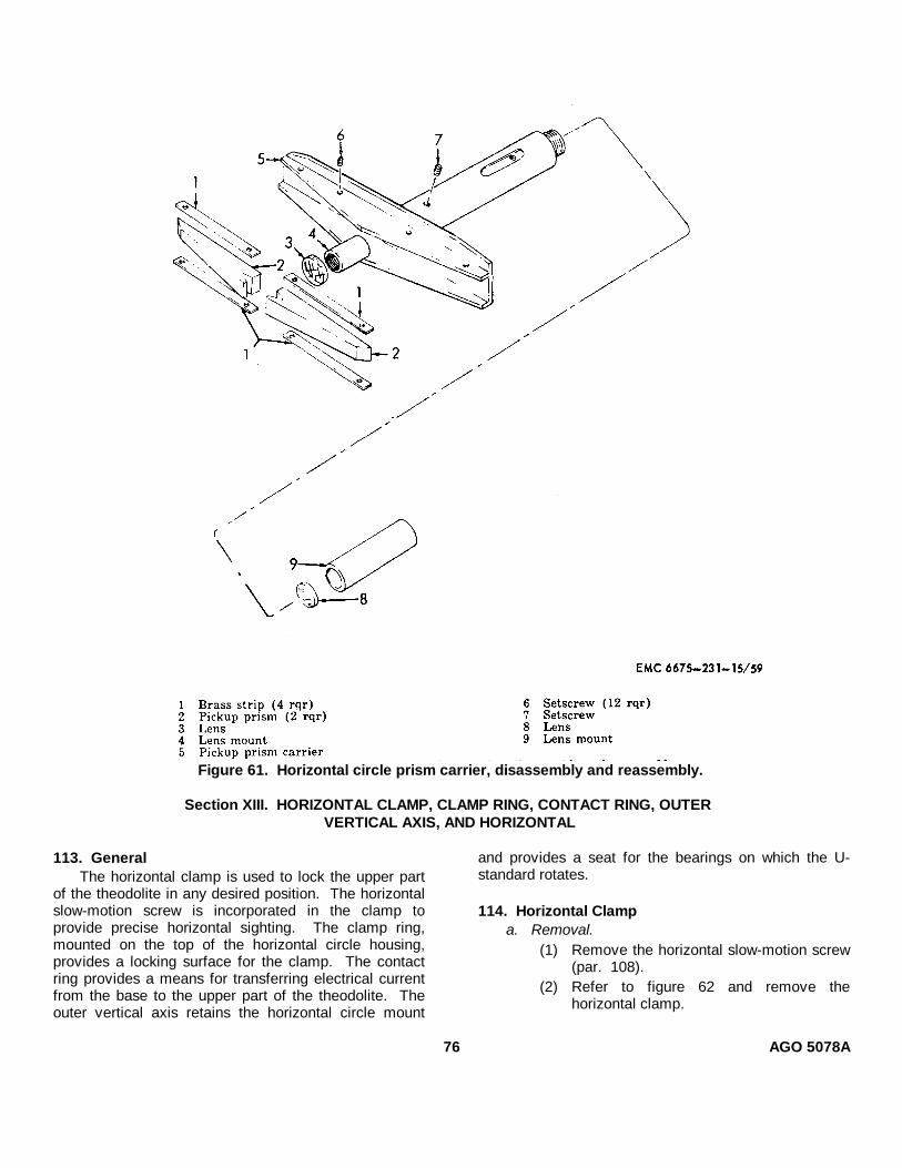
Figure 61. Horizontal circle prism carrier, disassembly and reassembly.
Section XIII. HORIZONTAL CLAMP, CLAMP RING, CONTACT RING, OUTERVERTICAL AXIS, AND HORIZONTAL
113. GeneralThe horizontal clamp is used to lock the upper part
of the theodolite in any desired position. The horizontalslow-motion screw is incorporated in the clamp toprovide precise horizontal sighting. The clamp ring,mounted on the top of the horizontal circle housing,provides a locking surface for the clamp. The contactring provides a means for transferring electrical currentfrom the base to the upper part of the theodolite. Theouter vertical axis retains the horizontal circle mount
and provides a seat for the bearings on which the U-standard rotates.
114. Horizontal Clampa. Removal.
(1) Remove the horizontal slow-motion screw(par. 108).
(2) Refer to figure 62 and remove thehorizontal clamp.
76 AGO 5078A
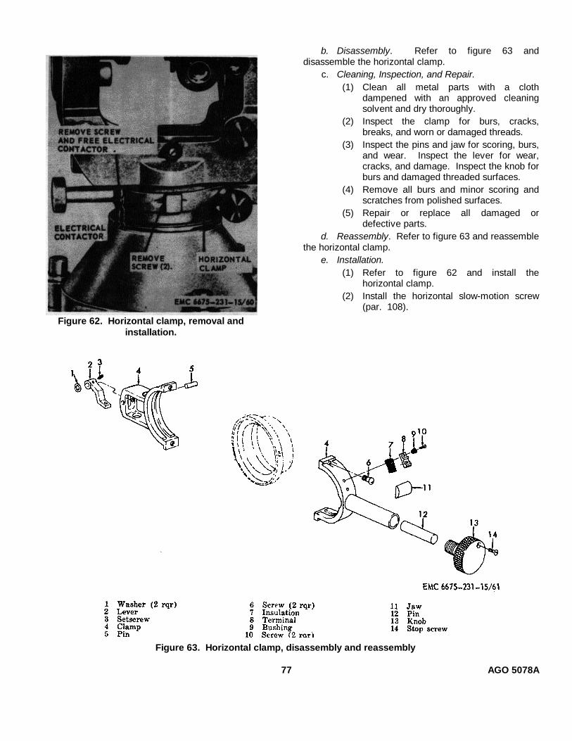
Figure 62. Horizontal clamp, removal andinstallation.
b. Disassembly. Refer to figure 63 anddisassemble the horizontal clamp.
c. Cleaning, Inspection, and Repair.(1) Clean all metal parts with a cloth
dampened with an approved cleaningsolvent and dry thoroughly.
(2) Inspect the clamp for burs, cracks,breaks, and worn or damaged threads.
(3) Inspect the pins and jaw for scoring, burs,and wear. Inspect the lever for wear,cracks, and damage. Inspect the knob forburs and damaged threaded surfaces.
(4) Remove all burs and minor scoring andscratches from polished surfaces.
(5) Repair or replace all damaged ordefective parts.
d. Reassembly. Refer to figure 63 and reassemblethe horizontal clamp.
e. Installation.(1) Refer to figure 62 and install the
horizontal clamp.(2) Install the horizontal slow-motion screw
(par. 108).
Figure 63. Horizontal clamp, disassembly and reassembly
77 AGO 5078A
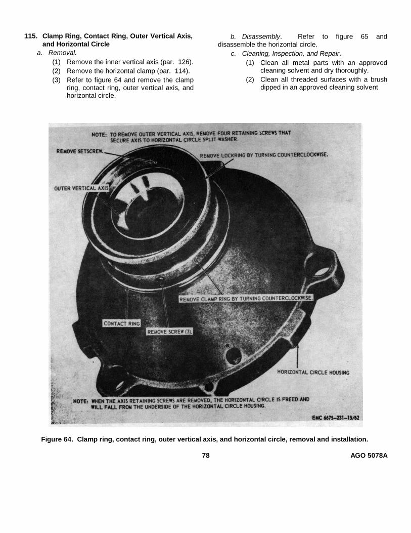
115. Clamp Ring, Contact Ring, Outer Vertical Axis,and Horizontal Circle
a. Removal.(1) Remove the inner vertical axis (par. 126).(2) Remove the horizontal clamp (par. 114).(3) Refer to figure 64 and remove the clamp
ring, contact ring, outer vertical axis, andhorizontal circle.
b. Disassembly. Refer to figure 65 anddisassemble the horizontal circle.
c. Cleaning, Inspection, and Repair.(1) Clean all metal parts with an approved
cleaning solvent and dry thoroughly.(2) Clean all threaded surfaces with a brush
dipped in an approved cleaning solvent
Figure 64. Clamp ring, contact ring, outer vertical axis, and horizontal circle, removal and installation.
78 AGO 5078A

Figure 65. Horizontal circle, disassembly and reassembly.
(3) Clean the horizontal circle with a lenscloth or lens tissue. Inspect the circle forchips, cracks, or other damage. Inspectthe teeth of the circle mount for wear,burs, and damage.
(4) Inspect the clamp ring, contact ring, andouter vertical axis for dents, cracks, andother defects.
(5) Inspect the ball bearings for wear,scratches, rust, and other defects.
(6) Straighten all dents and replace alldamaged parts that cannot be repaired.
d. Reassembly. Refer to figure 65 and reassemblethe horizontal circle.
e. Installation.(1) Refer to figure 64 and install the outer
vertical axis, contact ring, clamp ring, andhorizontal circle.
(2) Install the horizontal clamp (par. 114).(3) Install the inner vertical axis (par. 126).
Section XIV. LEVELING SCREWS, HORIZONTAL CIRCLE DRIVE, ILLUMINATIONSOCKET, AND HORIZONTAL CIRCLE HOUSING
116. GeneralThe leveling screws are the means by which the
theodolite is precisely leveled as indicated by the platelevel. The horizontal circle drive is used to rotate thehorizontal circle to any desired position without rotatingthe U-standard. The illumination socket, located on thecircle housing, provides a mount for the horizontal circleillumination mirror and for the light housing when theelectrical illumination system is utilized. The horizontalcircle housing comprises the lower part of the theodoliteto which the leveling screws and star plate are mounted.
It also supports the U-standard and contains thehorizontal circle and vertical axis.117. Leveling Screws
a. Removal and Disassembly.(1) Remove the star plate (par. 54).(2) Refer to figure 66 and remove and
disassemble the leveling screws.b. Cleaning, Inspection, and Repair.
(1) Clean all parts with an approved cleaningsolvent and dry thoroughly.
(2) Inspect the threaded surfaces on the pointscrew, knob, and nut for wear
79 AGO 5078A
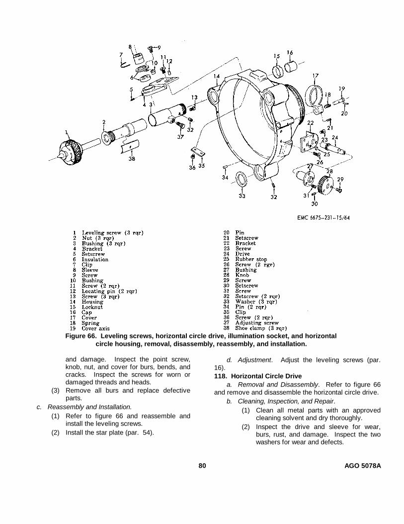
Figure 66. Leveling screws, horizontal circle drive, illumination socket, and horizontalcircle housing, removal, disassembly, reassembly, and installation.
and damage. Inspect the point screw,knob, nut, and cover for burs, bends, andcracks. Inspect the screws for worn ordamaged threads and heads.
(3) Remove all burs and replace defectiveparts.
c. Reassembly and Installation.(1) Refer to figure 66 and reassemble and
install the leveling screws.(2) Install the star plate (par. 54).
d. Adjustment. Adjust the leveling screws (par.16).118. Horizontal Circle Drive
a. Removal and Disassembly. Refer to figure 66and remove and disassemble the horizontal circle drive.
b. Cleaning, Inspection, and Repair.(1) Clean all metal parts with an approved
cleaning solvent and dry thoroughly.(2) Inspect the drive and sleeve for wear,
burs, rust, and damage. Inspect the twowashers for wear and defects.
80 AGO 5078A
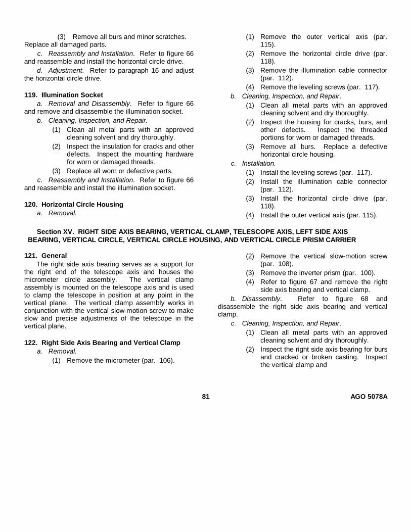
(3) Remove all burs and minor scratches.Replace all damaged parts.
c. Reassembly and Installation. Refer to figure 66and reassemble and install the horizontal circle drive.
d. Adjustment. Refer to paragraph 16 and adjustthe horizontal circle drive.
119. Illumination Socketa. Removal and Disassembly. Refer to figure 66
and remove and disassemble the illumination socket.b. Cleaning, Inspection, and Repair.
(1) Clean all metal parts with an approvedcleaning solvent and dry thoroughly.
(2) Inspect the insulation for cracks and otherdefects. Inspect the mounting hardwarefor worn or damaged threads.
(3) Replace all worn or defective parts.c. Reassembly and Installation. Refer to figure 66
and reassemble and install the illumination socket.
120. Horizontal Circle Housinga. Removal.
(1) Remove the outer vertical axis (par.115).
(2) Remove the horizontal circle drive (par.118).
(3) Remove the illumination cable connector(par. 112).
(4) Remove the leveling screws (par. 117).b. Cleaning, Inspection, and Repair.
(1) Clean all metal parts with an approvedcleaning solvent and dry thoroughly.
(2) Inspect the housing for cracks, burs, andother defects. Inspect the threadedportions for worn or damaged threads.
(3) Remove all burs. Replace a defectivehorizontal circle housing.
c. Installation.(1) Install the leveling screws (par. 117).(2) Install the illumination cable connector
(par. 112).(3) Install the horizontal circle drive (par.
118).(4) Install the outer vertical axis (par. 115).
Section XV. RIGHT SIDE AXIS BEARING, VERTICAL CLAMP, TELESCOPE AXIS, LEFT SIDE AXISBEARING, VERTICAL CIRCLE, VERTICAL CIRCLE HOUSING, AND VERTICAL CIRCLE PRISM CARRIER
121. GeneralThe right side axis bearing serves as a support for
the right end of the telescope axis and houses themicrometer circle assembly. The vertical clampassembly is mounted on the telescope axis and is usedto clamp the telescope in position at any point in thevertical plane. The vertical clamp assembly works inconjunction with the vertical slow-motion screw to makeslow and precise adjustments of the telescope in thevertical plane.
122. Right Side Axis Bearing and Vertical Clampa. Removal.
(1) Remove the micrometer (par. 106).
(2) Remove the vertical slow-motion screw(par. 108).
(3) Remove the inverter prism (par. 100).(4) Refer to figure 67 and remove the right
side axis bearing and vertical clamp.b. Disassembly. Refer to figure 68 and
disassemble the right side axis bearing and verticalclamp.
c. Cleaning, Inspection, and Repair.(1) Clean all metal parts with an approved
cleaning solvent and dry thoroughly.(2) Inspect the right side axis bearing for burs
and cracked or broken casting. Inspectthe vertical clamp and
81 AGO 5078A
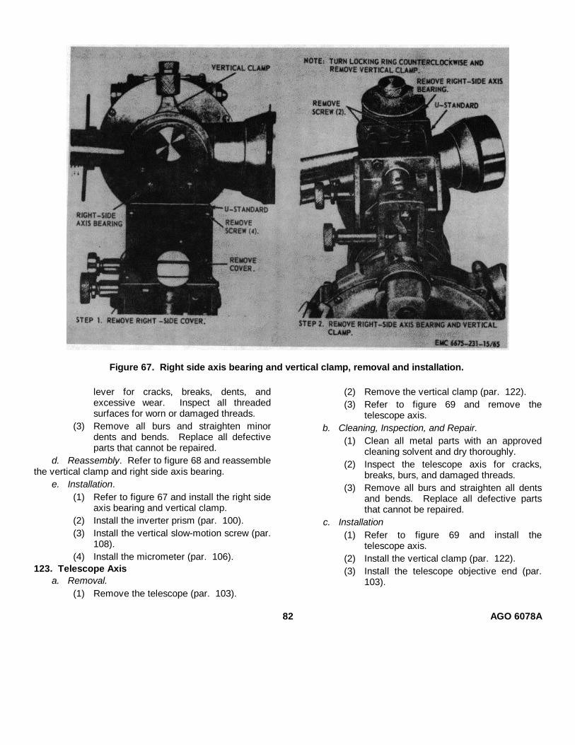
Figure 67. Right side axis bearing and vertical clamp, removal and installation.
lever for cracks, breaks, dents, andexcessive wear. Inspect all threadedsurfaces for worn or damaged threads.
(3) Remove all burs and straighten minordents and bends. Replace all defectiveparts that cannot be repaired.
d. Reassembly. Refer to figure 68 and reassemblethe vertical clamp and right side axis bearing.
e. Installation.(1) Refer to figure 67 and install the right side
axis bearing and vertical clamp.(2) Install the inverter prism (par. 100).(3) Install the vertical slow-motion screw (par.
108).(4) Install the micrometer (par. 106).
123. Telescope Axisa. Removal.
(1) Remove the telescope (par. 103).
(2) Remove the vertical clamp (par. 122).(3) Refer to figure 69 and remove the
telescope axis.b. Cleaning, Inspection, and Repair.
(1) Clean all metal parts with an approvedcleaning solvent and dry thoroughly.
(2) Inspect the telescope axis for cracks,breaks, burs, and damaged threads.
(3) Remove all burs and straighten all dentsand bends. Replace all defective partsthat cannot be repaired.
c. Installation(1) Refer to figure 69 and install the
telescope axis.(2) Install the vertical clamp (par. 122).(3) Install the telescope objective end (par.
103).
82 AGO 6078A

Figure 68. Right side axis bearing and vertical clamp, disassembly and reassembly.
124. Left Side Axis Bearing, Vertical Circle, VerticalCircle Housing, and Vertical Circle PrismCarrier a. Removal.
(1) Remove the collimation level and leverassembly (par. 93).
(2) Remove the vertical circle illuminationprism (par. 98).
(3) Remove the telescope axis (par. 123).
(4) Refer to figure 70 and remove the leftside axis bearing, vertical circle, verticalcircle housing, and vertical circle prismcarrier.
b. Disassembly. Refer to figure 71 anddisassemble the left side axis bearing, vertical circle,vertical circle housing, and vertical circle prism carrier.
c. Cleaning, Inspection, and Repair.
(1) Clean all metal parts with an approvedcleaning solvent and dry thoroughly.
Clean all threaded parts with a brushdipped in an approved cleaning solvent.
(2) Clean the lenses, and vertical circleprisms with lens tissue or a lens cloth. Besure no lint remains on the vertical circleafter cleaning.
(3) Inspect the lenses and prisms for chips,cracks, scratches, and etching. Inspectthe left side axis bearing and verticalcircle prism carrier for cracks, burs, andwear.
(4) Inspect the circle holding spring plate,prism mounts, vertical circle housing, andlens mounts for bends, dents, burs,cracks, and other damage.
(5) Remove all burs and straighten minordents and bends. Replace all damagedparts that cannot be repaired.
d. Reassembly. Refer to figure 71 and reassemblethe vertical circle prism carrier, vertical
AGO 5078A83
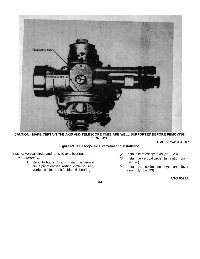
CAUTION: MAKE CERTAIN THE AXIS AND TELESCOPE TUBE ARE WELL SUPPORTED BEFORE REMOVINGSCREWS.
EMC 6675-231-15/67Figure 69. Telescope axis, removal and installation.
housing, vertical circle, and left side axis bearing.e. Installation.
(1) Refer to figure 70 and install the verticalcircle prism carrier, vertical circle housing,vertical circle, and left side axis bearing.
(2) Install the telescope axis (par. 123).(3) Install the vertical circle illumination prism
(par. 98).(4) Install the collimation level and lever
assembly (par. 93).
AGO 6078A84

Figure 70. Left side axis bearing, vertical circle, vertical circle housing, andvertical circle prism carrier, removal and installation.
AGO 5078A85
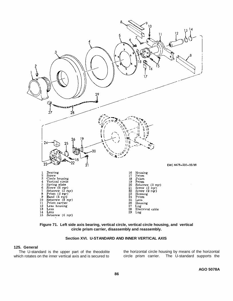
Figure 71. Left side axis bearing, vertical circle, vertical circle housing, and verticalcircle prism carrier, disassembly and reassembly.
Section XVI. U-STANDARD AND INNER VERTICAL AXIS
125. GeneralThe U-standard is the upper part of the theodolite
which rotates on the inner vertical axis and is secured tothe horizontal circle housing by means of the horizontalcircle prism carrier. The U-standard supports the
AGO 5078A86
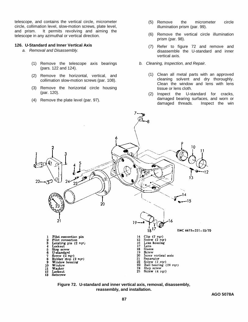
telescope, and contains the vertical circle, micrometercircle, collimation level, slow-motion screws, plate level,and prism. It permits revolving and aiming thetelescope in any azimuthal or vertical direction.
126. U-Standard and Inner Vertical Axisa. Removal and Disassembly.
(1) Remove the telescope axis bearings(pars. 122 and 124).
(2) Remove the horizontal, vertical, andcollimation slow-motion screws (par. 108).
(3) Remove the horizontal circle housing(par. 120).
(4) Remove the plate level (par. 97).
(5) Remove the micrometer circleillumination prism (par. 99).
(6) Remove the vertical circle illuminationprism (par. 98).
(7) Refer to figure 72 and remove anddisassemble the U-standard and innervertical axis.
b. Cleaning, Inspection, and Repair.
(1) Clean all metal parts with an approvedcleaning solvent and dry thoroughly.Clean the window and lens with lenstissue or lens cloth.
(2) Inspect the U-standard for cracks,damaged bearing surfaces, and worn ordamaged threads. Inspect the win
Figure 72. U-standard and inner vertical axis, removal, disassembly,reassembly, and installation.
AGO 5078A87
dow and lens for chips, cracks, andetchings.
(3) Inspect the inner vertical axis forexcessive wear, burs, and damagedthreads.
(4) Remove all burs. Replace all defectiveparts that cannot be repaired.
c. Reassembly and Installation.(1) Refer to figure 72 and reassemble and
install the inner vertical axis and U-standard.
(2) Install the vertical circle illumination prism(par. 98).
(3) Install the micrometer circle illuminationprism (par. 99).
(4) Install the plate level (par. 97).
(5) Install the horizontal circle housing
(par. 120).
(6) Install the horizontal, vertical, andcollimation slow-motion screws (par. 108).
(7) Install the telescope axis bearings
(pars. 122 and 124).
Section XVII. ILLUMINATION SYSTEM
127. General
The illumination system consists of two lighthousings and a battery box with a rheostat to control theintensity of light illuminating the horizontal, vertical, andmicrometer circles. A hand light that plugs into thebattery box is also provided for general external lightingpurposes.
128. Battery Box Assembly
a. Disassembly. Refer to figure 73 anddisassemble the battery box assembly.
b. Cleaning, Inspection, and Repair.
(1) Clean all metal parts with an approvedcleaning solvent and dry thoroughly.Wipe all corrosion from terminals andcontacts. Wipe dirt and other foreignmatter from cables, lamp trunk, springs,washers, and rheostat.
(2) Inspect the cables and contacts forcracked, swollen, or damaged insulation,broken wires, and defective terminals.Inspect the springs for bends, breaks, andfatigue.
(3) Inspect the lamp trunk for cracks andother damage. Inspect the rheostat forimproper operation and other damage.Inspect the sockets for cracks and wear.Inspect the springs for bends, breaks, andfatigue. Inspect the contacts and slidelever for wear, burs, and bends.
(4) Inspect the battery box for dents, cracks,and defective mounting bracket, clamps,and carrying strap.
(5) Remove all burs and straighten minordents. Replace all defective parts thatcannot be repaired.
c. Reassembly. Refer to figure 73 and reassemblethe battery box assembly.
129. Light Housings, Connector Cable, and HandLight
a. General. When not in use the light housings arestowed in the accessory case, and the hand light andconnector cable are stowed in the battery box.
b. Disassembly. Refer to figure 74 anddisassemble the light housings, connector cable, andhand light.
c. Cleaning, Inspection, and Repair.(1) Clean all metal parts with an approved
cleaning solvent and dry thoroughly.
(2) Inspect the lamps for defects. Inspect allelectrical contacts for breaks, wear, andcorrosion. Inspect the light housing glassfilter for damage.
(3) Inspect insulation for cracks, wear, anddamage. Inspect the electrical cable forbreaks and frayed insulation. Inspect thecable connectors for breaks and defectiveterminals.
(4) Inspect the housings and tubes for dents,rust, burs, and other defects.
(5) Remove all burs and straighten minordents. Replace all defective parts thatcannot be repaired.
d. Reassembly. Refer to figure 74 and reassemblethe light housings, connector cable, and hand light.
AGO 5078A
88
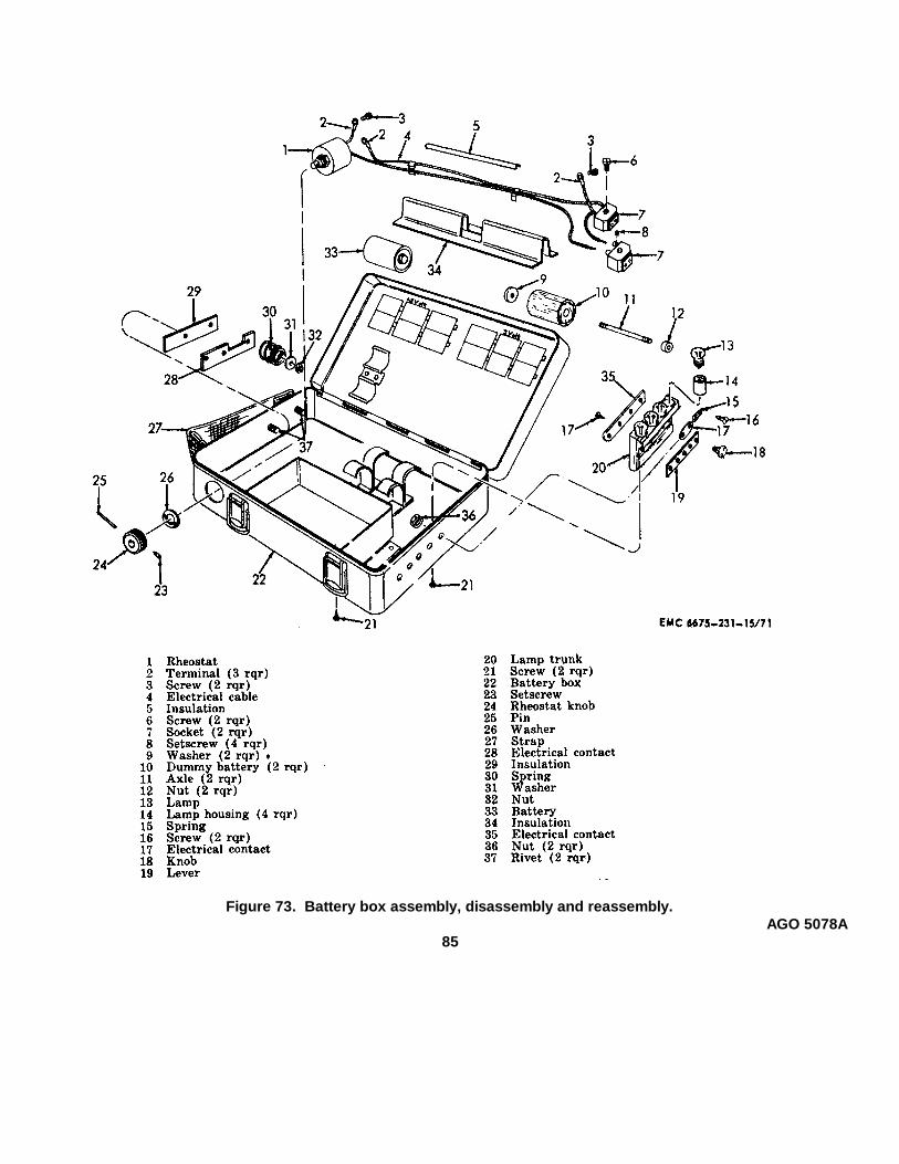
Figure 73. Battery box assembly, disassembly and reassembly.AGO 5078A
85
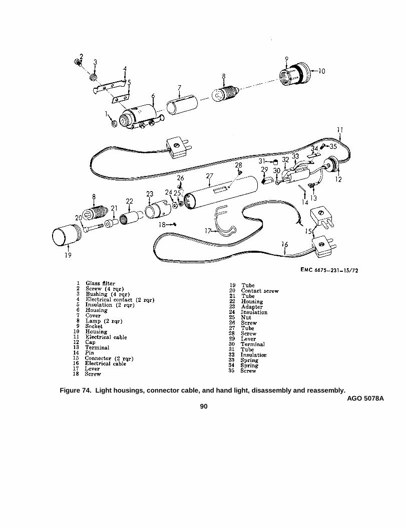
Figure 74. Light housings, connector cable, and hand light, disassembly and reassembly.AGO 5078A
90
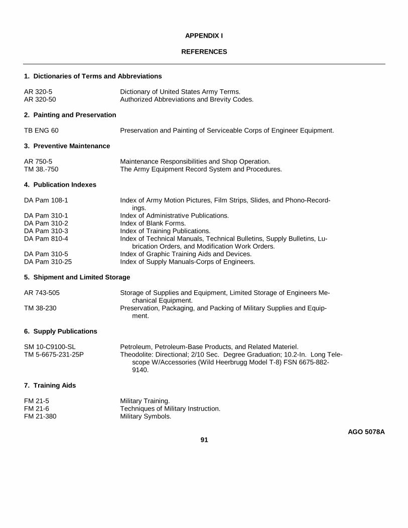
APPENDIX I
REFERENCES
1. Dictionaries of Terms and Abbreviations
AR 320-5 Dictionary of United States Army Terms.AR 320-50 Authorized Abbreviations and Brevity Codes.
2. Painting and Preservation
TB ENG 60 Preservation and Painting of Serviceable Corps of Engineer Equipment.
3. Preventive Maintenance
AR 750-5 Maintenance Responsibilities and Shop Operation.TM 38.-750 The Army Equipment Record System and Procedures.
4. Publication Indexes
DA Pam 108-1 Index of Army Motion Pictures, Film Strips, Slides, and Phono-Record-ings.
DA Pam 310-1 Index of Administrative Publications.DA Pam 310-2 Index of Blank Forms.DA Pam 310-3 Index of Training Publications.DA Pam 810-4 Index of Technical Manuals, Technical Bulletins, Supply Bulletins, Lu-
brication Orders, and Modification Work Orders.DA Pam 310-5 Index of Graphic Training Aids and Devices.DA Pam 310-25 Index of Supply Manuals-Corps of Engineers.
5. Shipment and Limited Storage
AR 743-505 Storage of Supplies and Equipment, Limited Storage of Engineers Me-chanical Equipment.
TM 38-230 Preservation, Packaging, and Packing of Military Supplies and Equip-ment.
6. Supply Publications
SM 10-C9100-SL Petroleum, Petroleum-Base Products, and Related Materiel.TM 5-6675-231-25P Theodolite: Directional; 2/10 Sec. Degree Graduation; 10.2-In. Long Tele-
scope W/Accessories (Wild Heerbrugg Model T-8) FSN 6675-882-9140.
7. Training Aids
FM 21-5 Military Training.FM 21-6 Techniques of Military Instruction.FM 21-380 Military Symbols.
AGO 5078A91
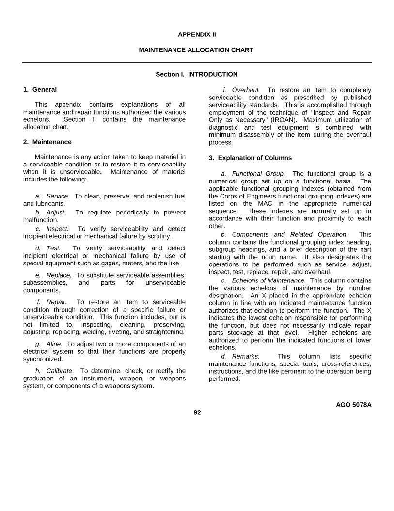
APPENDIX II
MAINTENANCE ALLOCATION CHART
Section I. INTRODUCTION
1. General
This appendix contains explanations of allmaintenance and repair functions authorized the variousechelons. Section II contains the maintenanceallocation chart.
2. Maintenance
Maintenance is any action taken to keep materiel ina serviceable condition or to restore it to serviceabilitywhen it is unserviceable. Maintenance of materielincludes the following:
a. Service. To clean, preserve, and replenish fueland lubricants.
b. Adjust. To regulate periodically to preventmalfunction.
c. Inspect. To verify serviceability and detectincipient electrical or mechanical failure by scrutiny.
d. Test. To verify serviceability and detectincipient electrical or mechanical failure by use ofspecial equipment such as gages, meters, and the like.
e. Replace. To substitute serviceable assemblies,subassemblies, and parts for unserviceablecomponents.
f. Repair. To restore an item to serviceablecondition through correction of a specific failure orunserviceable condition. This function includes, but isnot limited to, inspecting, cleaning, preserving,adjusting, replacing, welding, riveting, and straightening.
g. Aline. To adjust two or more components of anelectrical system so that their functions are properlysynchronized.
h. Calibrate. To determine, check, or rectify thegraduation of an instrument, weapon, or weaponssystem, or components of a weapons system.
i. Overhaul. To restore an item to completelyserviceable condition as prescribed by publishedserviceability standards. This is accomplished throughemployment of the technique of "Inspect and RepairOnly as Necessary" (IROAN). Maximum utilization ofdiagnostic and test equipment is combined withminimum disassembly of the item during the overhaulprocess.
3. Explanation of Columns
a. Functional Group. The functional group is anumerical group set up on a functional basis. Theapplicable functional grouping indexes (obtained fromthe Corps of Engineers functional grouping indexes) arelisted on the MAC in the appropriate numericalsequence. These indexes are normally set up inaccordance with their function and proximity to eachother.
b. Components and Related Operation. Thiscolumn contains the functional grouping index heading,subgroup headings, and a brief description of the partstarting with the noun name. It also designates theoperations to be performed such as service, adjust,inspect, test, replace, repair, and overhaul.
c. Echelons of Maintenance. This column containsthe various echelons of maintenance by numberdesignation. An X placed in the appropriate echeloncolumn in line with an indicated maintenance functionauthorizes that echelon to perform the function. The Xindicates the lowest echelon responsible for performingthe function, but does not necessarily indicate repairparts stockage at that level. Higher echelons areauthorized to perform the indicated functions of lowerechelons.
d. Remarks. This column lists specificmaintenance functions, special tools, cross-references,instructions, and the like pertinent to the operation beingperformed.
AGO 5078A92
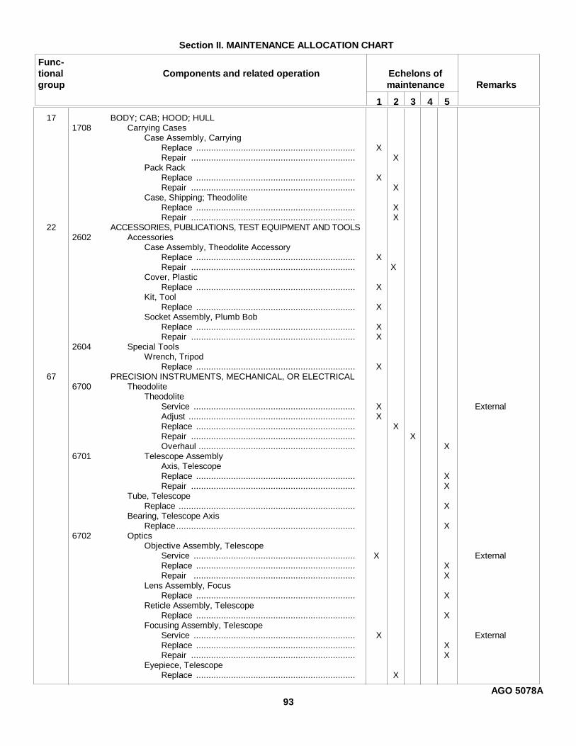
Section II. MAINTENANCE ALLOCATION CHART
Func-tional Components and related operation Echelons ofgroup maintenance Remarks
1 2 3 4 5
17 BODY; CAB; HOOD; HULL1708 Carrying Cases
Case Assembly, CarryingReplace ................................................................ XRepair .................................................................. X
Pack RackReplace ................................................................ XRepair .................................................................. X
Case, Shipping; TheodoliteReplace ................................................................ XRepair .................................................................. X
22 ACCESSORIES, PUBLICATIONS, TEST EQUIPMENT AND TOOLS2602 Accessories
Case Assembly, Theodolite AccessoryReplace ................................................................ XRepair .................................................................. X
Cover, PlasticReplace ................................................................ X
Kit, ToolReplace ................................................................ X
Socket Assembly, Plumb BobReplace ................................................................ XRepair .................................................................. X
2604 Special ToolsWrench, Tripod
Replace ................................................................ X67 PRECISION INSTRUMENTS, MECHANICAL, OR ELECTRICAL
6700 TheodoliteTheodolite
Service ................................................................. X ExternalAdjust ................................................................... XReplace ................................................................ XRepair .................................................................. XOverhaul ............................................................... X
6701 Telescope AssemblyAxis, TelescopeReplace ................................................................ XRepair .................................................................. X
Tube, TelescopeReplace ....................................................................... X
Bearing, Telescope AxisReplace........................................................................ X
6702 OpticsObjective Assembly, Telescope
Service ................................................................. X ExternalReplace ................................................................ XRepair ................................................................. X
Lens Assembly, FocusReplace ................................................................ X
Reticle Assembly, TelescopeReplace ................................................................ X
Focusing Assembly, TelescopeService ................................................................. X ExternalReplace ................................................................ XRepair .................................................................. X
Eyepiece, TelescopeReplace ................................................................ X
AGO 5078A93
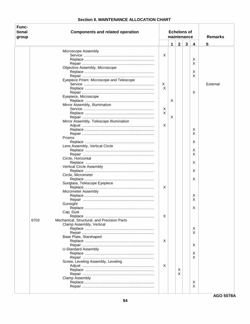
Section II. MAINTENANCE ALLOCATION CHART
Func-tional Components and related operation Echelons ofgroup maintenance Remarks
1 2 3 4 5
Microscope AssemblyService ................................................................. XReplace ................................................................. XRepair ................................................................... X
Objective Assembly, MicroscopeReplace ................................................................. XRepair ................................................................... X
Eyepiece Prism: Microscope and TelescopeService ................................................................. X ExternalReplace ................................................................ XRepair ................................................................... X
Eyepiece, MicroscopeReplace ................................................................ X
Mirror Assembly, IlluminationService .................................................................. XReplace ................................................................ XRepair ................................................................... X
Mirror Assembly, Telescope IlluminationAdjust ................................................................... XReplace ................................................................. XRepair ................................................................... X
PrismsReplace ................................................................ X
Lens Assembly, Vertical CircleReplace ................................................................ XRepair .................................................................. X
Circle, HorizontalReplace ................................................................ X
Vertical Circle AssemblyReplace ................................................................ X
Circle, MicrometerReplace ................................................................. X
Sunglass, Telescope EyepieceReplace ................................................................. X
Micrometer AssemblyReplace ................................................................. XRepair .................................................................. X
GunsightReplace ................................................................. X
Cap, DustReplace ................................................................ X
6703 Mechanical, Structural, and Precision PartsClamp Assembly, Vertical
Replace ................................................................ XRepair ................................................................... X
Base Plate, StarshapedReplace ................................................................ XRepair ................................................................... X
U-Standard AssemblyReplace ................................................................ XRepair .................................................................. X
Screw, Leveling Assembly, LevelingAdjust ................................................................... XReplace ................................................................ XRepair ................................................................... X
Clamp AssemblyReplace ................................................................. XRepair ................................................................... X
AGO 5078A94
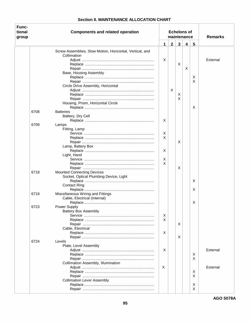
Section II. MAINTENANCE ALLOCATION CHART
Func-tional Components and related operation Echelons ofgroup maintenance Remarks
1 2 3 4 5
Screw Assemblies, Slow Motion, Horizontal, Vertical, andCollimation
Adjust ................................................................... X ExternalReplace ................................................................ XRepair ................................................................... X
Base, Housing AssemblyReplace ................................................................ XRepair .................................................................. X
Circle Drive Assembly, HorizontalAdjust ................................................................... XReplace ................................................................ XRepair .................................................................. X
Housing, Prism, Horizontal CircleReplace ................................................................. X
6708 BatteriesBattery, Dry Cell
Replace ................................................................ X6709 Lamps
Fitting, LampService ................................................................. XReplace ................................................................ XRepair ................................................................... X
Lamp, Battery BoxReplace ................................................................ X
Light, HandService ................................................................. XReplace ................................................................ XRepair .................................................................. X
6718 Mounted Connecting DevicesSocket, Optical Plumbing Device, Light
Replace ................................................................ XContact Ring
Replace ................................................................. X6719 Miscellaneous Wiring and Fittings
Cable, Electrical (Internal)Replace ................................................................. X
6723 Power SupplyBattery Box Assembly
Service ................................................................. XReplace ................................................................ XRepair .................................................................. X
Cable, ElectricalReplace ................................................................. XRepair ................................................................... X
6724 LevelsPlate, Level Assembly
Adjust ................................................................... X ExternalReplace ................................................................ XRepair ................................................................... X
Collimation Assembly, IlluminationAdjust ................................................................... X ExternalReplace ................................................................ XRepair .................................................................. X
Collimation Lever AssemblyReplace ................................................................. XRepair .................................................................. X
AGO 5078A95
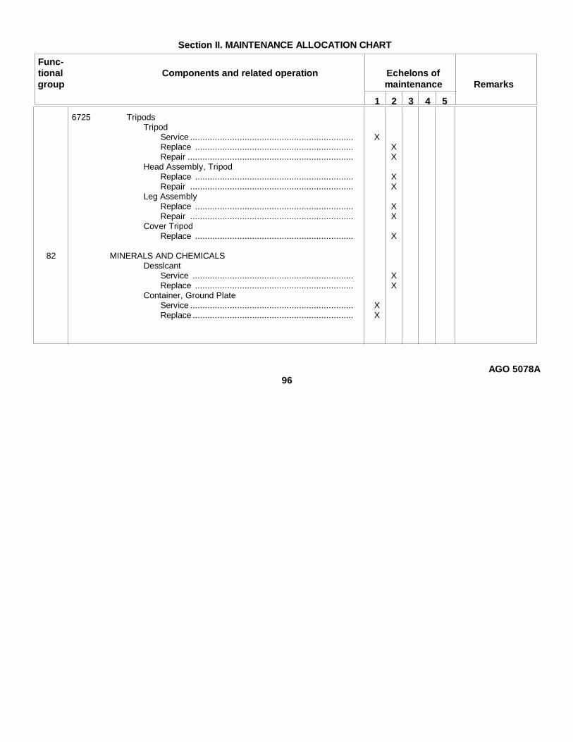
Section II. MAINTENANCE ALLOCATION CHART
Func-tional Components and related operation Echelons ofgroup maintenance Remarks
1 2 3 4 5
6725 TripodsTripod
Service .................................................................. XReplace ................................................................ XRepair ................................................................... X
Head Assembly, TripodReplace ................................................................ XRepair .................................................................. X
Leg AssemblyReplace ................................................................ XRepair .................................................................. X
Cover TripodReplace ................................................................ X
82 MINERALS AND CHEMICALSDesslcant
Service ................................................................. XReplace ................................................................ X
Container, Ground PlateService .................................................................. XReplace ................................................................. X
AGO 5078A96

APPENDIX III
BASIC ISSUE ITEMS LIST
Section I. INTRODUCTION1. General
Section II lists the accessories, tools, andpublications required in 1st echelon maintenance andoperation, initially issued with, or authorized for thetheodolite.
2. Explanation of Columns
a. Source Codes. The information provided ineach column is as follows:
(1) Technical service. This column lists thebasic number (or symbol) of the technicalservice assigned supply responsibility forthe part. Blank spaces denote Corps ofEngineers supply responsibility. GeneralEngineer supply parts are identified by theletters GE in parentheses, following thenomenclature in the description column.Other technical services basic numbers(or symbols) are 10-Quartermaster Corps11-Signal Corps 12-Adjutant General'sCorps
(2) Source. The selection status and sourceof supply for each part are indicated byone of the following code symbols:
(a) P-applied to high-mortality repairparts which are stocked in orsupplied from the technical servicedepot system, and authorized foruse at indicated maintenanceechelons.
(b) P1-applied to repair parts which arelow-mortality parts, stocked in orsupplied from technical servicedepots, and authorized forinstallation at indicatedmaintenance echelons.
(c) M-applied to repair parts which arenot procured or stocked but are tobe manufactured at indicatedmaintenance echelons.
(d) X2-applied to repair parts which arenot stocked. The indicatedmaintenance echelon requiring suchrepair parts will attempt to obtainthem through cannibalization; if notobtainable through cannibalization,such repair parts will berequisitioned with supportingjustification t h r o u g h normalsupply channels.
(3) Maintenance. The lowest maintenanceechelon authorized to use, stock, install,or manufacture the part is indicated by thefollowing code symbol:
O-Organizational Maintenance(1st and 2d Echelon)
(4) Recoverability. Repair parts and/or tooland equipment items that are recoverableare indicated by one of the following codesymbols:
(a) R-applied to repair parts andassemblies which are economicallyrepairable at field maintenancefacilities (3d and 4th echelons) andare normally furnished by supply onan exchange basis.
(b) T-applied to high-dollar valuerecoverable repair parts which aresubject to special handling and areissued on an exchange basis. Suchrepair parts are normally repaired oroverhauled at depot maintenancefacilities.
(c) U-applied to repair parts specificallyselected for salvage by reclamationunits because of precious metalcontent, critical materials, high-dollar value reusable casings,castings, and the like.
AGO 5078A97
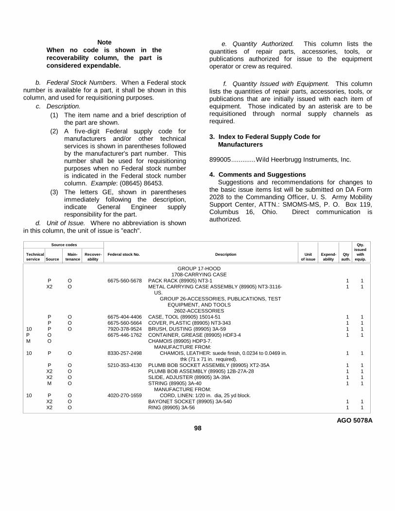
NoteWhen no code is shown in therecoverability column, the part isconsidered expendable.
b. Federal Stock Numbers. When a Federal stocknumber is available for a part, it shall be shown in thiscolumn, and used for requisitioning purposes.
c. Description.(1) The item name and a brief description of
the part are shown.(2) A five-digit Federal supply code for
manufacturers and/or other technicalservices is shown in parentheses followedby the manufacturer's part number. Thisnumber shall be used for requisitioningpurposes when no Federal stock numberis indicated in the Federal stock numbercolumn. Example: (08645) 86453.
(3) The letters GE, shown in parenthesesimmediately following the description,indicate General Engineer supplyresponsibility for the part.
d. Unit of Issue. Where no abbreviation is shownin this column, the unit of issue is "each".
e. Quantity Authorized. This column lists thequantities of repair parts, accessories, tools, orpublications authorized for issue to the equipmentoperator or crew as required.
f. Quantity Issued with Equipment. This columnlists the quantities of repair parts, accessories, tools, orpublications that are initially issued with each item ofequipment. Those indicated by an asterisk are to berequisitioned through normal supply channels asrequired.
3. Index to Federal Supply Code forManufacturers
899005.............Wild Heerbrugg Instruments, Inc.
4. Comments and SuggestionsSuggestions and recommendations for changes to
the basic issue items list will be submitted on DA Form2028 to the Commanding Officer, U. S. Army MobilitySupport Center, ATTN.: SMOMS-MS, P. O. Box 119,Columbus 16, Ohio. Direct communication isauthorized.
Source codes Qty.issued
Technical Main- Recover- Federal stock No. Description Unit Expend- Qty withservice Source tenance ability of issue ability auth. equip.
GROUP 17-HOOD1708-CARRYING CASE
P O 6675-560-5678 PACK RACK (89905) NT3-1 1 1X2 O METAL CARRYING CASE ASSEMBLY (89905) NT3-3116- 1 1
US.GROUP 26-ACCESSORIES, PUBLICATIONS, TEST
EQUIPMENT, AND TOOLS2602-ACCESSORIES
P O 6675-404-4406 CASE, TOOL (89905) 15014-51 1 1P O 6675-560-5664 COVER, PLASTIC (89905) NT3-343 1 1
10 P O 7920-378-9524 BRUSH, DUSTING (89905) 3A-59 1 1P O 6675-446-1762 CONTAINER, GREASE (89905) HDF3-4 1 1M O CHAMOIS (89905) HDP3-7.
MANUFACTURE FROM:10 P O 8330-257-2498 CHAMOIS, LEATHER: suede finish, 0.0234 to 0.0469 in. 1 1
thk (71 x 71 in. required).P O 5210-353-4130 PLUMB BOB SOCKET ASSEMBLY (89905) XT2-35A 1 1X2 O PLUMB BOB ASSEMBLY (89905) 12B-27A-28 1 1X2 O SLIDE, ADJUSTER (89905) 3A-39A 1 1M O STRING (89905) 3A-40 1 1
MANUFACTURE FROM:10 P O 4020-270-1659 CORD, LINEN: 1/20 in. dia, 25 yd block.
X2 O BAYONET SOCKET (89905) 3A-540 1 1X2 O RING (89905) 3A-56 1 1
AGO 5078A98
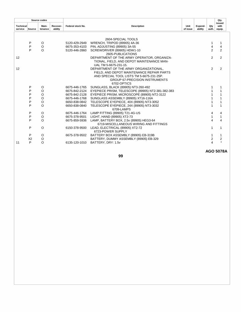
Source codes Qty.issued
Technical Main- Recover- Federal stock No. Description Unit Expend- Qty withservice Source tenance ability of issue ability auth. equip.
2604-SPECIAL TOOLSP O 5120-429-2949 WRENCH, TRIPOD (89905) 4A-36 1 1P O 6675-353-4103 PIN, ADJUSTING (89905) 3A-55 4 4P O 5120-446-2860 SCREWDRIVER (89905) HDW1-10 2 2
2605-PUBLICATIONS12 DEPARTMENT OF THE ARMY OPERATOR, ORGANIZA- 2 2
TIONAL, FIELD, AND DEPOT MAINTENANCE MAN-UAL TM 5-6675-231-15.
12 DEPARTMENT OF THE ARMY ORGANIZATIONAL, 2 2FIELD, AND DEPOT MAINTENANCE REPAIR PARTSAND SPECIAL TOOL LISTS TM 5-6675-231-25P.
GROUP 67-PRECISION INSTRUMENTS6702-OPTICS
P O 6675-446-1765 SUNGLASS, BLACK (89905) NT3-260-492 1 1P O 6675-842-2124 EYEPIECE PRISM, TELESCOPE (89905) NT2-381-382-383 1 1P O 6675-842-2128 EYEPIECE PRISM, MICROSCOPE (89905) NT2-3122 1 1P O 6675-446-1768 SUNGLASS ASSEMBLY (89905) XT16-116A 1 1P O 6650-838-0842 TELESCOPE EYEPIECE, 40X (89905) NT3-3052 1 1P O 6650-838-0840 TELESCOPE EYEPIECE, 24X (89905) NT3-3032 1 1
6709-LAMPSP O 6675-446-1764 LAMP FITTING (89905) T21-4G-US 4 4P O 6675-378-9501 LIGHT, HAND (89905) XT2-73 1 1P O 6675-859-5936 LAMP, BATTERY BOX, 2.5v (89905) HEG3-64 4 4
6719-MISCELLANEOUS WIRING AND FITTINGSP O 6150-378-9500 LEAD, ELECTRICAL (89905) XT2-72 1 1
6723-POWER SUPPLYP O 6675-378-9502 BATTERY BOX ASSEMBLY (89905) EB-319B 1 1X2 O BATTERY, DUMMY ASSEMBLY (89905) EB-329 2 2
11 P O 6135-120-1010 BATTERY, DRY: 1.5v 4 *
AGO 5078A99

INDEX
Paragraph Page Paragraph PageAdjustments: Clamps:
Collimation level ................. 16i 25 Horizontal ...................................... 114 76Collimation slow-motion screw 16e 25 Ring .............................................. 115 78General .............................. 16a 25 Cold weather operations ................. 18 26Horizontal circle drive ......... 16f 25 Collimation:Horizontal collimation error .. 16h 25 Error adjustment, horizontal ........... 16h 25Horizontal slow-motion screw 16c 25 Level and lever assembly .............. 92, 93 58Leveling screws .................. 16g 25 Level adjustment .................. 16i 25Plate level .......................... 16b 25 Level bubble does not stay inVertical slow-motion screw .. 16d 25 center ................................... 37, 82 39, 55
Axis: ............................................ Slow-motion screw ......................... 107, 108 71Inner vertical ....................... 125, 126 86, 87 Adjustment ........................... 16e 25Outer vertical ...................... 115 78 Connector cable ................................... 129 88Telescope ........................... 123 82 Connector, illumination cable ................ 112 74
Axis bearings: ............................... Contact ring .......................................... 115 78Left side .............................. 124 83 Controls and instruments ...................... 13, 14 22Right side ........................... 122 81 Cover, horizontal circle housing ............ 110 73
Basic issue tools and equipment ... 24 32 Daily services, operator's ...................... 29 33Battery box assembly.................... 128 88 Data (See Tabulated data)Battery replacement ..................... 32 38 Demolition:Bearings:....................................... General .......................................... 60 46
Left side axis ....................... 124 83 To render the theodolite inopera-Right side axis .................... 122 81 tive ....................................... 61 46
Training ......................................... 62 46Cable, connector .......................... 129 88 Description ........................................... 3, 69 3,41Cable connector, illumination ........ 112 74 Differences in models ........................... 5 8Carrier:. Dismantling for movement 11 22Horizontal circle prism................... 111 73 Drive, horizontal circle .......................... 118 80Vertical circle prism....................... 124 83 Adjustment ..................................... 16f 25Carrying case ............................... 47 39 Dusty area operation ............................. 20 27Carrying case and pack rack: ........ Equipment:Carrying case................................ 47 39 Basic issue tools and....................... 24 32General ........................................ 46 39 Conversion .................................... 10 12Pack rack ..................................... 48 41 Dismantling for movement ............. 11 22Case, carrying .............................. 47 39 Inspecting ...................................... 8 9Circle and micrometer images will not Servicing ........................................ 8 9
focus ....................................... 39 39 Setting-up instructions afterCircle drive, horizontal .................. 118 80 movement ............................ 12 22
Adjustment ......................... 16f 25 Setting-up instructions .................... 9 12Circle housing: .............................. Special tools and ............................ 23, 71 32, 51
Horizontal ........................... 120 81 Specially designed tools and........... 73 51Vertical ............................... 124 83 Unloading ...................................... 6 9
Circle illumination prisms: Unpacking ...................................... 7 9Micrometer ......................... 99 63 Eyepiece prisms ................................... 51 42Horizontal ........................... 110 73 Eyepieces:Vertical ............................... 98 62 Eyepiece prisms ............................. 51 42
Circle prism carrier:....................... General .......................................... 49 41Horizontal ........................... 111 73 Microscope .................................... 50 42Vertical ............................... 124 83 Sunglasses .................................... 52 4
Circles:.......................................... Telescope ...................................... 50 42Horizontal ........................... 115 78 Field and depot maintenance repairVertical ............................... 124 83 parts .............................................. 72 51
Clamp, vertical ............................. 122 81 Forms, record and report....................... 2, 68 3, 49
AGO 5078A100

Paragraph Page Paragraph PageHand light ..................................... 129 88 Inspection of theodolite in storage ........ 66 48Horizontal circle: Instruments and controls ...................... 13, 14 22
Drive ....................................... 118 80 Inverter prism ....................................... 100 64Adjustment ......................... 16f 25
Graduations: Lamp replacement ............................... 31 38Not at right angles to line Left side axis bearing ............................ 124 83dividing the two images ....87 55 Level and lever assembly, collimation .. 92, 93 58Unequal ...........................86 55 Level adjustment ............................ 16i 25
Hard to move .......................... 43, 79 39, 55 Level, plate .......................................... 97 61Has unequal light or no light .... 84 55 Adjustment ..................................... 16 25Horizontal circle ....................... 115 78 Horizontal collimation error ad-Housing ................................... 120 81 justment ................................ 16h 25Housing cover ......................... 110 73 Leveling screws, horizontal circleIllumination prism .................... 110 73 drive, illumination socket, and hori-Prism carrier ............................ 111 73 zontal circle housing:
Horizontal circle illumination prism General .......................................... 116 79and housing cover, horizontal circle Horizontal circle drive ..................... 118 80prism carrier, and illumination ca- Adjustment ........................... 16f 25ble connector: Horizontal circle housing ................. 120 81General .................................... 109 72 Illumination socket ......................... 119 81Horizontal circle housing cover. Leveling screws ............................. 117 79
and illumination prism ......... 110 73 Adjustment ........................................... 16g 25Horizontal circle prism carrier ... 111 73 Leveling screws too tight or too loose ... 44, 77 39, 55Illumination cable connector ..... 112 74 Lever assembly, collimation level and .. 92, 93 58
Horizontal clamp, clamp ring, contact Level adjustment .................................. 16i 25ring, outer vertical axis, and hori Light, hand ........................................... 129 88zontal circle: Light housings ................................ 129 88Clamp ring, contact ring, outer.. Lights in vertical and horizontal
vertical axis, and horizontal . circles unequal or absent ............... 40 39circle ................................... 115 78 Loading the theodolite for shipment....... 64 47
General .................................... 113 76 Lubrication:Horizontal clamp .......................... 114 76 Detailed information ............................. 27 32Horizontal collimation error-adjust . General information ............................. 26 32
ment......................................... 16h 25Horizontal, vertical, and collimation Maintenance:
slow-motion screws ................. 107,108 71 Of theodolite in storage .................. 66 48Adjustment .............................. 16c, 16d, 16e 25 Operator's:
Hot weather operation . ............... 19 26 Battery replacement ............. 32 38Humid conditions operation .......... 21 27 Lamp replacement................. 31 38Housing cover, horizontal circle .... 110 73 Repair parts:Housings: Field and depot maintenance 72 51
Light ........................................ 129 88 ...Organizational maintenance 25 32Horizontal circle ....................... 120 81 Services (See Preventive mainVertical circle ........................... 124 83 tenance services)
Micrometer ........................................... 105, 106 69Identification and data ................... 4 8 Micrometer circle:Illumination cable connector.......... 112 74 Has unequal light or no light ........... 89 59Illumination mirrors ........... 55, 56, 90, 91 43, 56 Illumination prism ........................... 99 63Illumination prisms: Microscope eyepiece ............................ 50 42
Horizontal circle ....................... 110 73 Microscope, telescope, and reticleMicrometer circle ..................... 99 63 mirror:Vertical circle ........................... 98 62 General .......................................... 101 65
Illumination socket ....................... 119 81 Microscope .................................... 102 65Illumination system: Reticle mirror ................................. 104 69
Battery box assembly .............. 128 88 Telescope ...................................... 103 66Fails to function ....................... 41, 83 39, 55 Mirrors:Faulty or fails to function .......... 41 39 Illumination 55, 56, 90, 91 43, 56General ................................... 127 88 Reticle ........................................... 104 69Light housings, connector cable, Models, difference in ............................ 5 8and hand light .......................... 129 88 Movement to a new worksite:
Inner vertical axis ......................... 125, 126 26,87 Dismantling for ............................... 11 22Inspecting and servicing equipment 8 9 Setting-up instructions after............. 12 22
AGO 5078A101

Paragraph Page Paragraph PageOperation of theodolite:................. Quarterly preventive maintenance
Adjustments ............................ 16 25 services .......................................... 30 33General ................................... 15 25 Rack, pack ........................................... 48 41In dusty or sandy areas............. 20 27 Rainy conditions operation ................... 21 27In extreme cold (Below 0o F.) ... 18 26 Record and report forms........................ 2, 68 3, 49In extreme heat ....................... 19 26 Repair parts:In salt water areas .................... 22 28 Field and depot maintenance .......... 72 51In sandy areas ......................... 20 27 Organizational ................................ 25 32Theodolite operation................. 17 26 Replacement:Under humid conditions ........... 21 27 Battery ........................................... 32 38Under rainy or humid conditions 21 27 Lamp ............................................. 31 38
Operator's daily services .............. 29 33 Report forms ........................................ 2, 68 3,49Operator's maintenance: Right side axis bearing, vertical
Battery replacement ................ 32 38 clamp, telescope axis, left side axisLamp replacement ................... 31 38 bearing, vertical circle, vertical
Organizational maintenance repair circle housing, arid vertical circleparts ........................................ 25 32 prism carrier:
Outer vertical axis ........................ 115 78 General .......................................... 121 81Left side axis bearing, vertical
Pack rack ...................................... 48 41 circle, vertical circle housing,Parts (See Repair parts) and vertical circle prism car-Plate level .................................... 97 60 rier ........................................ 124 83
Adjustment .............................. 16b 25 Right side axis bearing and ver-Horizontal collimation error ad-. tical clamp ............................ 122 81
justment............................... 16h1 25 Telescope axis ............................... 123 82Plate level bubble does not stay in Rings:
center ...................................... 36, 81 39, 55 Clamp ............................................ 115 78Plate level, vertical circle illumination Contact .......................................... 115 78
prism, micrometer circle illumina - Salt water area operation ............... 22 28tion prism, and inverter prism: Sandy area operation ........................... 20 27General ................................... 96 60 Scope .............................................. 1, 67 3, 49Inverter prism .......................... 100 64 Screws:Micrometer circle illumination ... Leveling ......................................... 117 79
prism .................................. 99 63 Adjustment ........................... 16g 25Plate level ............................... 97 60 Slow-motion:
Adjustment ......................... 16b 25 Collimation ..................................... 107, 108 71Horizontal collimation error Adjustment ........................... 16e 25adjustment .......................... 16h 25 Horizontal ...................................... 107, 108 71
Vertical circle illumination prism 98 62 Adjustment ........................... 16c 25Plate level vial defective .............. 80 55 Vertical .......................................... 107,108 71Plate, star . .................................. 53,54,94 95 43,60 Adjustment ........................... 16d 25Plumb bob..................................... 59 45 Services (See Preventive maintenancePreparation of theodolite: services)
For shipment ........................... 63 47 Setting-up instructions after move-For storage .............................. 65 47 ment .............................................. 12 22
Preventive maintenance services: Setting-up instructions .......................... 9 12General ................................... 28 33 Shipment:Operator's daily services ......... 29 33 Loading the theodolite for ............... 64 47
(Also see Operator's mainte- Preparation of theodolite for ........... 63 47nance) Slow-motion screws:Quarterly ............................. 30 33 Collimation . .................................. 107, 108 71
Prism carriers: Adjustment ........................... 16e 25Horizontal circle ....................... 111 73 Horizontal ...................................... 107, 108 71
Adjustment ........................... 16c 25Vertical..................................... 124 83 Vertical .......................................... 107, 108 71
Prisms: Adjustment ........................... 16d 25Eyepiece ................................. 51 42 Socket, illumination .............................. 119 81Horizontal circle illumination..... 110 73 Special tools and equipment ................ 23, 71 32, 51Inverter .................................... 100 64 Specially designed tools and equip-Micrometer circle illumination ... 99 63 ment .............................................. 73 51Vertical circle illumination......... 98 62 Star plate .................................... 53, 54, 94, 95 43, 60
AGO 5078A102
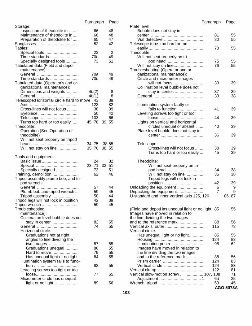
Paragraph Page Paragraph PageStorage: Plate level:
Inspection of theodolite in ........ 66 48 Bubble does not stay inMaintenance of theodolite in..... 66 48 center ............................................ 81 55Preparation of theodolite for ..... 65 47 Vial defective ................................. 80 55
Sunglasses . ................................ 52 42 Telescope turns too hard or tooTables: easily .............................................. 78 55
Special tools ............................ 23 2 Theodolite:Time standards ........................ 70b 49 Will not seat properly on tri-Specially designed tools ........... 73 51 pod head .............................. 75 55
Tabulated data (Field and depot Will not stay on line......................... 76 55maintenance): Troubleshooting (Operator and orGeneral ................................... 70a 49 ganizational maintenance):Time standards ........................ 70b 49 Circle and micrometer images
Tabulated data (Operator's and or- will not focus.......................... 39 39ganizational maintenance): Collimation level bubble does notDimensions and weights .......... 4b(2) 8 stay in center. ........................ 37 39General ................................... 4b(1) 8 General .......................................... 33 38
Telescope:Horizontal circle hard to move 43 39Axis ......................................... 123 82 Illumination system faulty orCross-lines will not focus .......... 38 39 fails to function ..................... 41 39Eyepiece .................................. 50 42 Leveling screws too tight or tooTelescope … ............................ 103 66 loose ..................................... 44 39Turns too hard or too easily ..... 45, 78 39, 55 Lights on vertical and horizontal
Theodolite: circles unequal or absent ...... 40 39Operation (See Operation of Plate level bubble does not stay intheodolite) center .................................... 36 39Will not seat properly on tripodhead ........................................ 34, 75 38,55 Telescope:Will not stay on line ................. 35, 76 38, 55 Cross-lines will not focus ....... 38 39
Turns too hard or too easily ... 45 39Tools and equipment:
Basic issue ............................... 24 32 Theodolite:Special .................................... 23, 71 32, 51 Will not seat properly on tri-Specially designed ................... 73 51 pod head .............................. 34 38
Training, demolition ...................... 62 46 Will not stay on line ............... 35 38Tripod assembly plumb bob, and tri- Tripod legs will not lock in
pod wrench: position ................................. 42 39General ................................... 57 44 Unloading the equipment ...................... 6 9Plumb bob and tripod wrench ... 59 45 Unpacking the equipment...................... 7 9Tripod assembly ................... 58 44 U-standard and inner vertical axis 125, 126 86, 87
Tripod legs will not lock in position 42 39Tripod wrench ............................... 59 45Troubleshooting (Field and depotHas unequal light or no light 85 55
maintenance): Images have moved in relation toCollimation level bubble does not the line dividing the two images
stay in center ....................... 82 55 and to the reference mark .................... 88 56General ................................... 74 55 Vertical axis, outer ................................ 115 78Horizontal circle: Vertical circle:
Graduations not at right Has unequal light or no light............ 85 55angles to line dividing the Housing ......................................... 124 83two images ......................... 87 55 Illumination prism ........................... 98 62Graduations unequal............ 86 55 Images have moved in relation toHard to move ...................... 79 55 the line dividing the two imagesHas unequal light or no light 84 55 and to the reference mark .............. 88 56
Illumination system fails to func- Prism carrier .................................. 124 83tion . .................................. 83 55 Vertical circle ................................. 124 83
Leveling screws too tight or too Vertical clamp ...................................... 122 81loose.................................... 77 55 Vertical slow-motion screw . ................ 107, 108 71
Micrometer circle has unequal .. Adjustment ................................... 1 6d 25light or no light .................... 89 56 Wrench, tripod ..................................... 59 45
AGO 5078A103
By Order of the Secretaries of the Army and the Air Force:EARLE G. WHEELER,General, United States Army,
Official: Chief of Staff.J. C. LAMBERT,Major General, United States Army,The Adjutant General.
CURTIS E. LEMAY,Official: Chief of Staff, United States Air Force.
R. J. PUGH,Colonel, United States Air Force,Director of Administrative Services.
Distribution:Active Army:
USASA (2) Army Dep (2)DCSLOG (1) USA Trans Tml Comd (2)CNGB (1) Army Tml (1)TSG (1) USAMOCOM (2)CofEngrs (3) USAOSA (2)CSigO (1) Div Engr (2)CofT (1) Engr Dist (2)USA Maint Bd (1) Engr Fld Maint Shop (2)
ARTYBD (2) USAERDL (3)ARMBD (2) Engr Cen (5)
USAIB (2) AMS (3)USAARADBD (2) Chicago Engr Proc Ofc (10)USAAESWBD (2) USA Mbl Spt Cen (36)USAAVNBD (2) ESCO (10)USCONARC (3) Fld Comd, DASA (8)USAMC (5) USACOMZEUR (2)OS Maj Comd (5) except USAREUR Engr Sup Con Agcy (10)
USARJ (10) USAREUR Engr Proc Cen (2)MDW (1) MAAG (1)Armies (2) JBUSMC (1)Corps (2) Units org under fol TOE:USA Corps (1) Two copies each UNOINDC:Div (2) 5-48Engr Bde (1) 5-167USMA (2) 5-237 (5)Svc College (2) 5-262 (5)Br Svc Sch (2) except 5-267 (1)
USAES (100) 5-278 (5)GENDEP (OS) (10) 5-279Engr Dep (OS) (10) 5-327
NG: State AG (3).USAR: Units same as Active Army except allowance is one copy to each unit.For explanation of abbreviations used, see AR 320-50.
AGO 5078AU. S GOVERNMENT PRINTING OFFICE : 1993 0 - 342-421 (80234)

The Metric System and EquivalentsLinear Measure Liquid Measure
1 centiliter = 10 milliters = .34 fl. ounce1 centimeter = 10 millimeters = .39 inch 1 deciliter = 10 centiliters = 3.38 fl. ounces1 decimeter = 10 centimeters = 3.94 inches 1 liter = 10 deciliters = 33.81 fl. ounces1 meter = 10 decimeters = 39.37 inches 1 dekaliter = 10 liters = 2.64 gallons1 dekameter = 10 meters = 32.8 feet 1 hectoliter = 10 dekaliters = 26.42 gallons1 hectometer = 10 dekameters = 328.08 feet 1 kiloliter = 10 hectoliters = 264.18 gallons1 kilometer = 10 hectometers = 3,280.8 feet
Square MeasureWeights
1 sq. centimeter = 100 sq. millimeters = .155 sq. inch1 centigram = 10 milligrams = .15 grain 1 sq. decimeter = 100 sq. centimeters = 15.5 sq. inches1 decigram = 10 centigrams = 1.54 grains 1 sq. meter (centare) = 100 sq. decimeters = 10.76 sq. feet1 gram = 10 decigram = .035 ounce 1 sq. dekameter (are) = 100 sq. meters = 1,076.4 sq. feet1 decagram = 10 grams = .35 ounce 1 sq. hectometer (hectare) = 100 sq. dekameters = 2.47 acres1 hectogram = 10 decagrams = 3.52 ounces 1 sq. kilometer = 100 sq. hectometers = .386 sq. mile1 kilogram = 10 hectograms = 2.2 pounds1 quintal = 100 kilograms = 220.46 pounds Cubic Measure1 metric ton = 10 quintals = 1.1 short tons
1 cu. centimeter = 1000 cu. millimeters = .06 cu. inch1 cu. decimeter = 1000 cu. centimeters = 61.02 cu. inches1 cu. meter = 1000 cu. decimeters = 35.31 cu. feet
Approximate Conversion FactorsTo change To Multiply by To change To Multiply by
inches centimeters 2.540 ounce-inches Newton-meters .007062feet meters .305 centimeters inches .394yards meters .914 meters feet 3.280miles kilometers 1.609 meters yards 1.094square inches square centimeters 6.451 kilometers miles .621square feet square meters .093 square centimeters square inches .155square yards square meters .836 square meters square feet 10.764square miles square kilometers 2.590 square meters square yards 1.196acres square hectometers .405 square kilometers square miles .386cubic feet cubic meters .028 square hectometers acres 2.471cubic yards cubic meters .765 cubic meters cubic feet 35.315fluid ounces milliliters 29,573 cubic meters cubic yards 1.308pints liters .473 milliliters fluid ounces .034quarts liters .946 liters pints 2.113gallons liters 3.785 liters quarts 1.057ounces grams 28.349 liters gallons .264pounds kilograms .454 grams ounces .035short tons metric tons .907 kilograms pounds 2.205pound-feet Newton-meters 1.356 metric tons short tons 1.102pound-inches Newton-meters .11296
Temperature (Exact)°F Fahrenheit 5/9 (after Celsius °C
temperature subtracting 32) temperature

PIN: 026291-000

This fine document...
Was brought to you by me:
Liberated Manuals -- free army and government manuals
Why do I do it? I am tired of sleazy CD-ROM sellers, who take publicly available information, slap “watermarks” and other junk on it, and sell it. Those masters of search engine manipulation make sure that their sites that sell free information, come up first in search engines. They did not create it... They did not even scan it... Why should they get your money? Why are not letting you give those free manuals to your friends?
I am setting this document FREE. This document was made by the US Government and is NOT protected by Copyright. Feel free to share, republish, sell and so on.
I am not asking you for donations, fees or handouts. If you can, please provide a link to liberatedmanuals.com, so that free manuals come up first in search engines:
<A HREF=http://www.liberatedmanuals.com/>Free Military and Government Manuals</A>
– SincerelyIgor Chudovhttp://igor.chudov.com/
– Chicago Machinery Movers