department of the navy docket no. 101658 page 2 of 23 inside a 4.75” inner diameter (id) submarine...
TRANSCRIPT

DEPARTMENT OF THE NAVY
OFFICE OF COUNSEL
NAVAL UNDERSEA WARFARE CENTER DIVISION
1176 HOWELL STREET NEWPORT Rl 02841-1708
IN REPLY REFER TO
Attorney Docket No. 101658
15 Apr 14
The below identified patent application is available for
licensing. Requests for information should be addressed
to:
TECHNOLOGY PARTNERSHIP ENTERPRISE OFFICE
NAVAL UNDERSEA WARFARE CENTER
1176 HOWELL ST.
CODE 07TP, BLDG. 102T
NEWPORT, RI 02841
Serial Number 13/630,717
Filing Date 28 September 2012
Inventor Paul J. Vizzio
Address any questions concerning this matter to the
Office of Technology Transfer at (401) 832-1511.
DISTRIBUTION STATEMENT
Approved for Public Release
Distribution is unlimited

Report Documentation Page Form ApprovedOMB No. 0704-0188
Public reporting burden for the collection of information is estimated to average 1 hour per response, including the time for reviewing instructions, searching existing data sources, gathering andmaintaining the data needed, and completing and reviewing the collection of information. Send comments regarding this burden estimate or any other aspect of this collection of information,including suggestions for reducing this burden, to Washington Headquarters Services, Directorate for Information Operations and Reports, 1215 Jefferson Davis Highway, Suite 1204, ArlingtonVA 22202-4302. Respondents should be aware that notwithstanding any other provision of law, no person shall be subject to a penalty for failing to comply with a collection of information if itdoes not display a currently valid OMB control number.
1. REPORT DATE APR 2014 2. REPORT TYPE
3. DATES COVERED 00-00-2014 to 00-00-2014
4. TITLE AND SUBTITLE Motor Controlled Rotating Base For Directional Submarine Antennas
5a. CONTRACT NUMBER
5b. GRANT NUMBER
5c. PROGRAM ELEMENT NUMBER
6. AUTHOR(S) 5d. PROJECT NUMBER
5e. TASK NUMBER
5f. WORK UNIT NUMBER
7. PERFORMING ORGANIZATION NAME(S) AND ADDRESS(ES) Technology Partnership Enterprise Office,Naval Undersea WarfareCenter, 1176 Howell St.,Code 07TP, Bldg. 102T,Newport,RI,02841
8. PERFORMING ORGANIZATIONREPORT NUMBER
9. SPONSORING/MONITORING AGENCY NAME(S) AND ADDRESS(ES) 10. SPONSOR/MONITOR’S ACRONYM(S)
11. SPONSOR/MONITOR’S REPORT NUMBER(S)
12. DISTRIBUTION/AVAILABILITY STATEMENT Approved for public release; distribution unlimited
13. SUPPLEMENTARY NOTES
14. ABSTRACT
15. SUBJECT TERMS
16. SECURITY CLASSIFICATION OF: 17. LIMITATION OF ABSTRACT Same as
Report (SAR)
18. NUMBEROF PAGES
32
19a. NAME OFRESPONSIBLE PERSON
a. REPORT unclassified
b. ABSTRACT unclassified
c. THIS PAGE unclassified
Standard Form 298 (Rev. 8-98) Prescribed by ANSI Std Z39-18
Attorney Docket No. 101658
Page 1 of 23
MOTOR CONTROLLED ROTATING BASE
FOR DIRECTIONAL SUBMARINE ANTENNAS
STATEMENT OF GOVERNMENT INTEREST
[0001] The invention described herein may be manufactured and
used by or for the Government of the United States of America
for Governmental purposes without the payment of any royalties
thereon or therefore.
BACKGROUND OF INVENTION
1) Field of the Invention
[0002] The present invention is directed to directional
antennas and antenna radomes.
2) Description of Prior Art
[0003] The range of an antenna is based on its power divided
by its beam width, among other variables. Therefore,
directional antennas operate at greater ranges than omni
antennas of the same power, since directional antennas focus
their beam width on an area and omni antennas do not restrict
their beam width. The problem with directional antennas is that
to see in all directions, these antennas either have to rotate
or multiple antennas need to be used.
[0004] Two exemplary submarine antenna systems that utilize a
rotating directional antenna are the Submarine High Data Rate
(SubHDR) and the Type 8B/J Mod 3. However, neither antenna fits

Attorney Docket No. 101658
Page 2 of 23
inside a 4.75” inner diameter (ID) submarine radome. SubHDR is
a three-axis satellite communication (SATCOM) system that
features a rotating directional antenna that fits in a very
large enclosure (radome) that includes a half of a sphere of
radius two feet sitting on top of a two foot diameter cylinder
of height one foot that is on top of a one foot tall tapered
cone. SubHDR, while utilizing a rotating antenna, is extremely
large. Larger systems are easier to detect visually and by
radar.
[0005] The Type 8B/J Mod 3 is similar to SubHDR in that it is
a three-axis SATCOM system, but it fits inside a much smaller
radome with an outside diameter of 7.5”. Antenna systems that
have been used in 4.75” ID submarine radomes have been non-
rotating. These systems have either utilized omni-directional
antennas (one antenna that transmits/receives in all directions)
or an array containing more than one directional antenna. Using
multiple antennas creates two disadvantages, spreading power
among multiple antennas and requiring a larger enclosure to
house the antennas. Using multiple antennas means that the
power supplied to the system is split between each individual
antenna, and therefore the range of the entire system is based
on the power divided by the number of antennas used. Using
multiple antennas also creates size constraints because the size
taken up is always going to be larger that of one antenna.

Attorney Docket No. 101658
Page 3 of 23
Therefore, a single directional antenna is desired that can be
rotated as needed and can be contained within a smaller radome.
SUMMARY OF THE INVENTION
[0006] Exemplary embodiments in accordance with the present
invention are directed to an antenna radome assembly having a
radome base and an annular stationary bearing plate attached to
and spaced from the radome base. A dual channel rotary joint is
included in the assembly and is constructed from a fixed portion
that is attached to the stationary bearing plate and a rotating
portion extending through a central opening of the stationary
bearing plate. The rotating portion includes a pair of
connection terminals, one terminal for each channel. The
connection terminals are accessible from a second side of the
rotating platform opposite the first side.
[0007] A rotating platform is attached to the rotating
portion and is rotatable with the rotating portion of the rotary
joint. The rotating platform includes a circular recess
extending into the rotating platform from a first side. The
stationary bearing plate is disposed completely within the
circular recess. An annular bearing assembly is also disposed
within the circular recess between the rotating platform and the
stationary bearing plate. The bearing assembly is in contact
with the rotation platform and the stationary bearing plate and

Attorney Docket No. 101658
Page 4 of 23
the rotating platform rotates with respect to the stationary
bearing plate and the radome base.
[0008] A radome is attached to the radome base to cover the
stationary bearing plate and the rotating platform. A
directional antenna is attached to the second side of the
rotating platform opposite the first side and is covered by the
radome. The directional antenna includes two co-axial
connections. Each co-axial connection is attached to one of the
connection terminals in the rotary joint. The directional
antenna extends from the second side of the rotating platform a
distance of less than about 5.5 inches.
BRIEF DESCRIPTION OF THE DRAWINGS
[0009] A more complete understanding of the invention and
many of the attendant advantages thereto will be readily
appreciated as the same becomes better understood by reference
to the following detailed description when considered in
conjunction with the accompanying drawings wherein like
reference numerals and symbols designate identical or
corresponding parts throughout the several views and wherein:
[0010] Fig. 1 is a representation of an embodiment of the
antenna radome assembly in accordance with the present
invention.

Attorney Docket No. 101658
Page 5 of 23
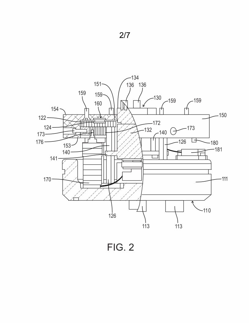
[0011] Fig. 2 is a partial cut-away view of an embodiment of
the side of the radome base, stationary platform and rotating
platform assemblies of the antenna radome assembly.
[0012] Fig. 3 is a top view of an embodiment of the radome
base for use in the antenna radome assembly.
[0013] Fig. 4 is a side view an embodiment of the radome base
for use in the antenna radome assembly.
[0014] Fig. 5 is a perspective view an embodiment of the
radome base for use in the antenna radome assembly.
[0015] Fig. 6 is a top view of an embodiment of a stationary
bearing plate for use in the antenna radome assembly.
[0016] Fig. 7 is a side view of an embodiment of a stationary
bearing plate for use in the antenna radome assembly.
[0017] Fig. 8 is a perspective view of an embodiment of a
rotary joint for use in the antenna radome assembly.
[0018] Fig. 9 is an exploded perspective view of an
embodiment of a bearing assembly for use in the antenna radome
assembly.
[0019] Fig. 10 is a top view of an embodiment of a rotating
platform for use in the antenna radome assembly.
[0020] Fig. 11 is a side view of an embodiment of a rotating
platform for use in the antenna radome assembly.
[0021] Fig. 12 is a top view of an embodiment of an internal
gear for use in the antenna radome assembly.

Attorney Docket No. 101658
Page 6 of 23
DETAILED DESCRIPTION OF THE INVENTION
[0022] Referring initially to Fig. 1, exemplary embodiments
in accordance with the present invention are directed to an
antenna radome assembly 100 rotationally positional deployment
of a single directional antenna (not shown) in a compact radome
enclosure that is attached to vehicles such as surface water
vehicles and underwater vehicles including unmanned undersea
vehicles (UUVs). In general, the antenna radome assembly 100 is
constructed from a plurality of sub-assemblies including a base
assembly, a stationary stand, a bearing assembly, a rotating
platform, a motor drive, a positioning assembly, an antenna
system, and a radome.
[0023] Referring to Figs. 3-5, the base assembly 110
includes a radome base 111. A pair of radome base co-axial
cable connectors 113, e.g., two RF connectors, and a multiple
pin connector 114 are attached to the radome base.
[0024] In general, the radome base 111 is a disc having a
circular cavity 112 extending into the disc from one side. In
one embodiment, this disc has a diameter 115 of less than about
4.75 inches and a thickness 116 of about 1.3 inches. The
circular cavity 112 has a diameter 117 of less than about 3.75
inches and a depth 118 of about 0.75 inches. Suitable materials
for the radome base 111 include, but are not limited to,

Attorney Docket No. 101658
Page 7 of 23
stainless steel. Preferably, the radome base co-axial cable
connectors 113 and multiple pin connector 114 are disposed
completely within the circular cavity 112 such that the co-axial
cable connectors and multiple pin connector do not extend above
the circular cavity.
[0025] In one embodiment, the two radome base co-axial cable
connectors 113 are modified versions of D.G. O’Brien connector
#1100 011‐101, commercially available from Teledyne D.G.O’Brien,
Inc. of Seabrook, New Hampshire, USA. In order to reduce the
size of the antenna radome assembly 100, the D.G. O’Brien
connector is modified such that the blind mate connector is cut
down and replaced with a 90º SubMinature version A (SMA) coaxial
RF connector 119. These 90º connectors are arranged
perpendicular to the direction in which the co-axial cable
connectors 113 pass through the radome base 111.
[0026] The multiple pin connector 114 is also modified. In
one embodiment, the multiple pin connector 114 is a modified
Seacon–XSEE-12#20-BCR connector, commercially available from SEA
CON® of El Cajon, California, USA. In the modified multiple pin
connector 114, a threaded portion that would be located inside
the circular cavity 112 of the radome base 111 is removed, and
the resulting overall length or size is smaller and wires can be
easily attached to the pins 120. In one embodiment, the two co-

Attorney Docket No. 101658
Page 8 of 23
axial cable connectors 113 and the multiple pin connector 114
screw into the radome base.
[0027] Referring to Figs. 2 and 6-7, the stationary stand is
an assembly that includes an annular stationary bearing plate
122 that is attached to and spaced from the radome base 111.
The stationary bearing plate 122 is the main support and
functions as the static piece about which the directional
antenna rotates. Suitable materials for the stationary bearing
plate include, but are not limited to, aluminum. In one
embodiment, the stationary bearing plate has a diameter 123 of
about 3.5 inches and includes a central opening or aperture 125
and a concentric surface annular groove 124.
[0028] In order to attach the stationary bearing plate 122 to
the radome base 111, the stationary stand portion of the
assembly includes a plurality of stationary bearing plate
supports 126(Figs. 1 and 2). Each support 126 is attached to
and extends between the stationary bearing plate 122 and the
radome base 111 to space the stationary bearing plate from the
radome base. Preferably, the assembly includes four stationary
bearing plate supports 126. Suitable materials for the
stationary bearing plate supports include, but are not limited
to, aluminum.
[0029] Each stationary bearing plate support 126 can either
be a standoff or a machined rod with threaded rods inserted at

Attorney Docket No. 101658
Page 9 of 23
one end. In one embodiment, each stationary bearing plate
support 126 is about ¼” in diameter with two flat sides to aid
in assembly and is about 1.8 inches long. The rod has a #4‐40
threaded section at one end of length less than about 0.2 inches
from the bottom face and the other end has a tapped #4‐40 hole
with a depth of about ¼”. The rods are threaded into
corresponding holes on the radome base 111, and the stationary
bearing plate 122 is fastened to each stationary bearing plate
support 126 by four #4‐40 x ¼” countersunk cap screws.
[0030] Referring to Figs. 1, 2 and 8, the stationary stand
also includes a rotary joint 130. The rotary joint includes a
fixed portion 132 that is attached to the stationary bearing
plate and a rotating portion 134 that is rotatably engaged with
the fixed portion and extends through the central opening 125 of
the stationary bearing plate 122. Preferably, the rotary joint
130 is a dual channel rotary joint.
[0031] For the dual channel rotary joint 130, the rotating
portion includes a pair of connection terminals 136, one for
each channel. In one embodiment, the rotating portion of the
rotary joint 130 is formed as a male portion of a two-part keyed
connection. The fixed portion includes a pair of rotary joint
co-axial cable connectors 138 in communication with the pair of

Attorney Docket No. 101658
Page 10 of 23
connection terminals 136 and the pair of radome base co-axial
cable connectors 113.
[0032] In order to attached and to secure the rotary joint
130 to the stationary bearing plate 122, the stationary stand
portion of the assembly further includes a plurality of rotary
joint supports 140 attached to and extending between the
stationary bearing plate 122 and the fixed portion 132 of the
rotary joint 130 such that the rotary joint 130 is suspended by
the stationary bearing plate and the fixed portion 132 extends
towards the radome base 111 and is spaced from the radome base
111, i.e., the fixed portion 132 does not extend the entire
distance from the stationary bearing plate 122 to the radome
base 111. In order to facilitate the attachment of the rotary
joint supports 140 to the fixed portion 132, the fixed portion
includes a circular flange 141 running completely around the
circumference of the fixed portion 132.
[0033] Each rotary joint support 140 is similar in materials
and configuration to the stationary bearing plate supports 126.
However, the lengths of the rotary joint supports 140 are
shorter. In one embodiment, the assembly includes four rotary
joint supports that are ¼” diameter rods with two flat sides and
are about 0.78” long. The rotary joint supports 140 have a #4‐
40 tapped hole at each end of depth ¼”. The supports are
screwed to the stationary bearing plate 122 via four #4‐40 x ¼”

Attorney Docket No. 101658
Page 11 of 23
countersunk screws and are screwed at the other end to the
rotary joint via four #4‐40 x ¼” cap screws.
[0034] In general, the dual channel rotary joint 130 is used
to connect the radome base co-axial cable connectors 113 to the
rotating directional antenna system that includes, for example,
the directional antenna and a GPS unit. These connections are
made using co-axial cables. In order to reduce the space
requirements, two 90º SubMinature version A (SMA) coaxial RF
connectors 142 are connected to the two SMA ports 138 that
extend from the fixed portion 132 of the rotary joint 130. The
coaxial cables, e.g., two 0.141 coaxial cables, are connected
between these two 90º connectors 142 on the rotary joint and to
the radome base co-axial cable connectors 113. Without a rotary
joint, continuous rotations of the directional antenna would
result in the wrapping and twisting of the coaxial cables.
Suitable rotary joints are commercially available from the
Kevlin Corporation of Methuen, Massachusetts.
[0035] Referring to Figs. 1, 2, 9 and 10, the assembly
includes a rotating platform 150 that is attached to and
rotatable with the rotating portion 134 of the rotary joint 130.
The rotating platform 150 includes a circular recess 151
extending into the rotating platform 150 from a first side 153.
The annular stationary bearing plate 122 is disposed completely
within the circular recess 151 and is preferably arranged

Attorney Docket No. 101658
Page 12 of 23
concentric with the circular recess 151 and spaced from the
rotating platform 150 and the interior surfaces of the circular
recess 151 so that the rotating platform 150 can rotate freely
with respect to the stationary bearing plate 122.
[0036] In one embodiment, attachment of the rotating portion
130 to the rotating platform 150 and mutual, coordinated
rotation is provided by a central keyhole 155 disposed in the
circular recess 151 of the rotating platform 150. The circular
keyhole extends through the rotating platform to a second side
154 opposite the first side 153. The keyhole is configured as
the female portion of the two-part keyed connection. The
corresponding male portion found on the rotating portion 134
extends into the keyhole to attach the rotating portion to the
rotating platform. Therefore, the connection terminals 136 of
the rotary joint 130 are accessible from the second side of the
rotating platform 154.
[0037] In one embodiment, the rotating platform includes an
internal annular groove 152 disposed within and concentric with
the circular recess 151. The concentric surface annular groove
124 of the stationary bearing plate is disposed opposite the
internal annular groove 152.
[0038] The rotating platform 150 is constructed as a single
piece to which additional pieces are attached including the
directional antenna. Suitable materials for the rotating

Attorney Docket No. 101658
Page 13 of 23
platform 150 include, but are not limited to, aluminum. The
rotating platform sits on top of the stationary bearing plate
122 that is positioned within the circular recess 151 and
rotates relative to the stationary bearing plate 122 and the
radome base 111. Directional antennas are mounted to the second
side of the rotating platform using a plurality of fasteners 159
such as countersunk screws. In one embodiment, the directional
antenna is secured to the second side using six #4‐40 x 0.375”
countersunk screws.
[0039] Referring to Figs. 2 and 11, the assembly includes an
annular bearing assembly 160 disposed within the circular recess
151 between the rotating platform 150 and the stationary bearing
plate 122. The bearing assembly 160 is in contact with the
rotating platform 150 and the stationary bearing plate 122 to
facilitate rotation of the rotating platform with respect to the
stationary bearing plate and the radome base 111. In one
embodiment, the bearing assembly has a diameter 161 of less than
about 2.75 inches and a central hole 163 having a diameter of
about 2 inches. The bearing assembly includes a first annular
bearing surface 164 in contact with the rotating platform, a
second annular bearing surface 165 in contact with the
stationary bearing plate and a plurality of roller bearings 166
disposed between the first annular bearing surface 164 and the
second annular bearing surface 165. Suitable materials for the
Attorney Docket No. 101658
Page 14 of 23
bearing assembly include, but are not limited to steel, such as
stainless steel. The first annular bearing surface 164 rotates
with respect to the second annular bearing surface 165 over the
plurality of roller bearings 166. Preferably, the first annular
bearing surface is disposed within the internal circular groove
125, and the second annular bearing surface is disposed within
the surface annular groove 124 (Fig. 2).
[0040] Therefore, the bearing assembly 160 is configured as a
three part assembly. All three parts are commercially available
from McMaster-Carr of Robbinsville, NJ. The roller bearings 166
are preferably arranged as a thrust needle-roller bearing, which
is part number 5909K43, and the annular bearing surfaces 164
and 165 are bearing washers, which is part number 5909K56. The
bearing assembly 160 fits between the stationary bearing plate
122 and the rotating platform 150 in the appropriate annular
groove. The bearing assembly 160 allows the rotating platform
150 to rotate smoothly about the stationary bearing plate 122.
Washers are used because the stationary stand and the rotating
platform bearing surfaces are preferably aluminum and not hard
enough for the thrust bearing. These bearing surfaces would wear
and degrade the performance of the system over time. The lower
washer is also used to cover up recessed holes on the stationary
bearing plate, which otherwise would have created a non-flat
Attorney Docket No. 101658
Page 15 of 23
bearing surface that would accelerate wear and yield a less
smooth rotation.
[0041] In order to rotate the rotating platform 150 and the
directional antenna attached to the rotating platform, the
assembly of the present invention also includes a motor drive
assembly. Referring to Figs. 1, 2 and 12, this drive assembly
includes an internal gear 172 disposed in the circular recess
151 such that the stationary bearing plate is spaced from the
internal gear and is disposed between the internal gear and the
rotating platform 150 to secure the stationary bearing plate 122
in the circular recess 151.
[0042] Suitable internal gears are commercially available
from Stock Drive Products/Sterling Instrument of New Hyde Park,
New York and include, for example, part number S1E082M08S096.
As necessary, the internal gear is modified to fit inside the
circular recess 151 of the rotating platform 150 and is secured
using six radial screws 173, e.g., #2‐56 x ¼” cap screws. The
internal gear 172 is fastened to the rotating platform 150 after
the rotating platform has been placed on top of the stationary
bearing plate 122 and the internal gear 172 sits under the
stationary bearing plate and constrains the system vertically.
The inside diameter 174 of the internal gear is smaller than the
outside diameter 123 of the stationary bearing plate 122.
Therefore, the rotating platform 150 cannot be lifted off of the

Attorney Docket No. 101658
Page 16 of 23
stationary bearing plate 122 unless the internal gear 172 is
removed from the circular recess 151 of the rotating platform
150. There is a clearance between the bottom face of the
stationary stand and the top face of the gear so that the whole
assembly can move freely.
[0043] The assembly includes a motor 170 attached to the
radome base 111 and disposed between the radome base and the
internal gear 172. A pinion gear 176 is provided that is
attached to and rotatable by the motor. The pinion gear 176
engages gear teeth 175 disposed in the internal gear 172 to
rotate the rotating platform 150 relative to the radome base 11
and the stationary bearing plate 122. Suitable pinion gears are
commercially available from Stock Drive Products/Sterling
Instrument of New Hyde Park, New York, for example as part
number A 1B 1MY08006. Suitable materials for the pinion gear
176 include, but are not limited to, brass. The pinion gear is
fastened to the motor 170 by a pin or solder or any other
appropriate adhesive or bonding material. The pinion gear turns
176 the internal steel gear 172 that is attached to the rotating
platform 150.
[0044] Suitable motors include, but are not limited to, a
brushless DC motor that contains a relative encoder, for
positioning, and a spur gear head that creates a 22:1 gear
ratio. Suitable motors are commercially available from Micro Mo
Attorney Docket No. 101658
Page 17 of 23
of Clearwater, Florida as, for example, part number 1524‐
012SR/16A‐22:1/IE2‐512. This motor has 6 input/output wires
and that are attached to the corresponding pins 120 on the pin
connector 114 that is fastened to the radome base. The motor is
secured to the radome base using four aluminum motor supports
and an aluminum motor mounting plate. As with the stationary
bearing plate supports, the motor supports can be standoffs or
¼” diameter rods with two flat sides, .2” long #4‐40 threaded
section and a #4‐40 threaded hole of depth ¼” on the other side;
however the motor supports are 1.3” in length. The motor
supports are screwed into the corresponding holes on the radome
base. The motor mounting plate is screwed to the motor supports
via four #4‐40 x ¼” counter sunk screws. The motor is attached
to the mounting plate by two M2x.4 cap screws of length about
6mm.
[0045] Referring to Figs. 1 and 2, the assembly also includes
a positioning assembly. This positioning assembly includes a
first part 180 attached to the first side of the rotating
platform and rotatable with the rotating platform and a second
part 181 attached to the radome base 111. The first part passes
over the second part at a given point as the rotating platform
150 rotates relative to the radome base 111. Preferably, the
first part 180 is a magnet, and the second part 181 is a Hall

Attorney Docket No. 101658
Page 18 of 23
Effect sensor. The positioning system also includes an integral
encoder, which is located inside the motor 170. The incremental
encoder determines the position of the directional antenna
relative to a pre-determined reference point.
[0046] The magnet 180 is screwed to the underside of the
rotating platform 150 and when rotated, it passes directly above
the Hall Effect sensor 181, which creates an active low output
signal. The output signal is used to create the zero point upon
which the motor encoder output will be relative to. Knowing the
gear ratio and the position of the Hall Effect sensor 181, the
angle of the antenna can be determined. The electronics and
software that run and control the motor 170 and Hall Effect
sensor 181 are located external to the assembly, with the
signals being transmitted through the multiple pin connector
114.
[0047] The Hall effect sensor 181 snaps onto an aluminum Hall
effect sensor mounting plate, which is attached to the radome
base by a #2‐56 x ¼” cap screw and a Hall effect sensor support.
The Hall Effect sensor support, like the other supports, can be
a standoff or a rod with a threaded rod screwed into one side.
The Hall Effect sensor support is ¼” in diameter with two flat
sides, has a .2” long #4‐40 threaded section, a #4‐40 tapped
hole on the other side, and is .75” long. The Hall effect
sensor support is screwed into the corresponding hole on the

Attorney Docket No. 101658
Page 19 of 23
radome base and is secured to the Hall effect sensor mounting
plate by a #4‐40 x ¼” countersunk screw. The Hall Effect sensor
181 contains three wires, which are all connected to the pin
connector 114 on the radome base 111.
[0048] Referring to Fig. 1, the assembly includes a radome
190 attached to the radome base 111. The radome covers the
stationary bearing plate 122 and the rotating platform 150 and
defines a space 191 above the second side 154 of the rotating
platform 150 sufficient to hold a directional antenna (not
shown) or antenna assembly. In one embodiment, this space has a
length 192 from the second side to the radome of less than about
5.5 inches. Suitable materials for the radome include materials
that are transparent to the signals that are transmitted by or
received by the directional assembly. The radome 190 is a
composite piece used as a cover to protect the directional
antenna from weather and water while allowing the transmission
of signals. The radome 190 is pressure tested to ensure that it
withstands submarine standards.
[0049] The antenna system can include any directional antenna
that fits within the size constraints of the radome 190 and that
utilizes a maximum of two coaxial connections 113. In one
embodiment, the antenna system has a height of about 5.46
inches, an antenna SMA connection and a GPS SMA connection. In
accordance with exemplary embodiments of the present invention,

Attorney Docket No. 101658
Page 20 of 23
one directional antenna transmits and receives signals 360
degrees and is used inside a 4.75” submarine radome.
[0050] Advantages of the present invention over conventional
systems include allowing a directional antenna to be used inside
a smaller enclosure, i.e., the directional antenna fits inside a
5.3” outside diameter (OD) 193. In addition to being much
smaller, the assembly of the present invention is also much
lighter, which makes handling and installation easier.
[0051] The present invention is much more modular and
adaptable in that almost any antenna system (within size
constraints) can be placed on top of the stand with little
modifications. It is also better than the systems utilized in
current 4.75” submarine radomes because of the greater range.
It focuses its power on a smaller area than the omni-directional
antennas because it utilizes only one antenna rather than
multiple directional antenna systems. Using one antenna means
that power is not divided amongst multiple antennas, and since
just one antenna can be used it can be larger, and thus more
effective. Two other unique aspects of this invention are that
it can pass two RF paths through the rotating platform, and its
speed and position can be controlled and determined by the user.
[0052] In one embodiment, larger radomes are used by altering
the dimensions of some of the parts. Larger radomes would mean
that there is more internal space, and therefore larger antennas

Attorney Docket No. 101658
Page 21 of 23
could be used. Larger antennas are typically more powerful than
smaller antennas, and different sized antennas serve different
purposes. The present invention could also be changed if there
was more vertical space to work with, which would mean that the
supports could be longer, the 90 degree attachments might not
have to be used, and the Seacon and DG O’Brien connectors would
not have to be modified. The rotating platform can also be
changed so that it fits with different antennas by modifying the
number of screws and screw positions and using pegs instead of
screws, among other modifications.
[0053] In one embodiment, the present invention is made
stronger or lighter by using different materials for any of the
parts. Different motors and different gear heads may be used to
provide different torques and operating speeds. A different
model pin 26 connector, RF connectors, Hall Effect sensor, or
magnet could also be used. Different coaxial cables or rotary
joints could also be used such that the frequency of the antenna
signals can be optimized. This assembly can also be altered by
using more bearings or bearing surfaces to decrease friction.
Precision components may also be incorporated in, such as anti‐
backlash gears and gear heads.
[0054] It will be understood that many additional changes in
details, materials, steps, and arrangements of parts which have
been described herein and illustrated in order to explain the

Attorney Docket No. 101658
Page 22 of 23
nature of the invention, may be made by those skilled in the art
within the principle and scope of the invention as expressed in
the appended claims.
[0055] Finally, any numerical parameters set forth in the
specification and attached claims are approximations (for
example, by using the term “about”) that may vary depending upon
the desired properties sought to be obtained by the present
invention. At the very least, and not as an attempt to limit
the application of the doctrine of equivalents to the scope of
the claims, each numerical parameter should at least be
construed in light of the number of significant digits and by
applying ordinary rounding.

Attorney Docket No. 101658
Page 23 of 23
MOTOR CONTROLLED ROTATING BASE
FOR DIRECTIONAL SUBMARINE ANTENNAS
ABSTRACT
An antenna radome assembly has a radome base and an annular
stationary bearing plate attached to and spaced from the radome
base. A rotary joint has a fixed portion attached to the
stationary bearing plate and a rotating portion extending
through a central opening of the stationary bearing plate. A
rotating platform is attached to the rotating portion of the
rotary joint. The rotating platform includes a circular recess
extending into the rotating platform from a first side. The
stationary bearing plate is disposed completely within the
circular recess. An annular bearing assembly is disposed within
the circular recess between the rotating platform and the
stationary bearing plate. The bearing assembly is in contact
with the rotating platform and the stationary bearing plate, and
the rotating platform rotates with respect to the stationary
bearing plate and the radome base.

Application No. ??REPLACEMENT SHEET?
/71
FIG. 1
113
110
126 141 132
111
181126
180140173
136
134130
192
193
100
190
154
150
153
170
191
173140
113
Application No. ??REPLACEMENT SHEET?
/7
FIG. 2
170
141140
176
173124
122
154
153
159
151
160
136
130159
134
150
180181
111
110
173172
132 140
126
126
113
2
159
136
159
113

Application No. ??REPLACEMENT SHEET?
/7
FIG. 3
FIG. 4
FIG. 5
120
113
114
111112
117
114
120
119
112
113
113
111
110
115
110
118 116
112111
119
113
110
3

Application No. ??REPLACEMENT SHEET?
/7
FIG. 7
FIG. 6
123
122
124
125
124 125
4
122

Application No. ??REPLACEMENT SHEET?
/7
FIG. 8
130
134
132
136
141
138
142
142
138
136
5

Application No. ??REPLACEMENT SHEET?
/7
FIG. 9
FIG. 10
150
155
154
152
152154
150
151
153
155
6

Application No. ??REPLACEMENT SHEET?
/7
FIG. 12
FIG. 11
162
164
165 166
163
172
175
174
175
160
161
7