deposition and characterization of tialn thin film … - ijmm… · deposition and characterization...
TRANSCRIPT
DEPOSITION AND CHARACTERIZATION OF TiAlN THIN FILM USING
DC/RF MAGNETRON CO-SPUTTERING TECHNIQUE
1RAJEEV KUMAR & 2B.TIWARI
1RajKumar Goel Institute of Technology, Ghaziabad Affiliated to GBTU, Noida (U.P.), India. 2Devender Singh Institute of Technology and Management Ghaziabad Affiliated to GBTU, Noida (U.P.),
India.
ABSTRACT
The present paper discusses about deposition of TiAlN thin films by using Magnetron Co-
sputtering with both DC and RF power supplies. The substrate used for deposition is silicon.
Titanium aluminium nitride thin films have been deposited on silicon using an unbalanced
magnetron co-sputter arrangement with separate titanium and aluminium targets. A range of Ti/Al/N
compositions were produced by varying the RF power supply which is connected to the aluminum target.
The thin films were then examined using an atomic force microscope (AFM), a scanning electron
microscope (SEM), FTIR, corrosion analysis and the crystallography structure of the films were determined
by X-Ray diffraction. Aluminum, titanium and nitrogen compositions (wt. % and at. %) were determined
by using energy dispersive X-ray spectroscopy.
It was found that as the aluminum target power increases (100W, 125W, 150W, and 175W) the
compositions of aluminum changed and the color of the films changed from gold to a blue-red. An increase
in the aluminum content (10-20%) had a significant effect on the average roughness and RMS value of the
films. Surface measurement analysis using the AFM results revealed that as the aluminium content
increases the average roughness decreased.
KEYWORDS: Tialn Coating, Magnetron Co-Sputtering, FTIR, AFM, Corrosion Analysis, Nano-
Indentation, X-Ray Diffraction.
INTRODUCTION
Nitride based hard compound coatings are finding increasing applications because of their excellent
properties such as high hardness, wear resistance, thermal stability and corrosion resistance [1, 2]. In plastic
and metal working industries cutting, forming and punching operations are quite common. Very recently
Titanium Aluminum Nitride coatings have also been studied for applications other than tribology; e.g. in
satellite temperature control [3]. A fundamental advantage of TiAlN coatings is that they form a highly
adhesive, dense protective Aluminum trioxide film at their surface when heated, preventing further inward
diffusion of oxygen into the coated material [4]. In addition, they have lower thermal conductivity, making
International Journal of Metallurgical & Materials Science and Engineering (IJMMSE) ISSN 2278-2516 Vol.2, Issue 3 Sep 2012 11-21 © TJPRC Pvt. Ltd.,
12 Rajeev Kumar & B.Tiwari
particularly suitable as coatings for machining applications. The superior cutting behavior of TiAlN over
conventional binary coatings makes it a suitable candidate for high-speed cutting tools. Also TiN seems to be
a good coating to reduce adhesive wear, but not for all work-piece materials. TiAlN coatings offer better
suitability when oxidation resistance at higher temperature is required. TiAlN coatings deposited by PVD
techniques such as Sputtering have attracted much attention in the recent past due to their excellent anti-
oxidation properties and high hardness up to about 8000C and improved cutting performance especially in the
higher cutting speed range as compared to TiN coatings [5].
EXPERIMENTAL PROCEDURE
The demand for clean ultra high vacuum conditions during vacuum evaporation has been largely
responsible for the growth of highly specialized and scientifically based industry , so in addition to the rotary
pump, diffusion pump is used in the sputtering system. Diffusion pump is designated to operate in a
molecular flow regime and can function over pressure ranging from 5 X 10⁻² mbar to 5 X 10⁻⁶ mbar. This can
be obtained through the action of a fluid medium that is boiled and vaporized in a multistage, jet assembly.
As the oil vapor (silicon oil) steam emerges from the top nozzles, it collide with and imparts momentum to
residual gas molecules are drive towards the bottom of the pump, compressed at the exit side where they are
exhausted. The vacuum chamber is evacuated with the help of rotary and diffusion pump to 10-5 mbar and
after that DC/RF power is applied to the cathodes for sputtering with sustained plasma. For plasma
deposition, DC/RF magnetron Co-sputtering unit (VACUUM TECHNIQUE PVT LIMITED, Bangalore
India) is used. Vacuum chamber is cylindrical and made out of 12 mm thick ASIS -304L non-magnetic
quality stainless steel.
The TiAlN thin films are deposited on silicon substrate. For all the thin films deposited the
deposition conditions remain same except for the RF power which is connected with Aluminum target
duration of deposition. The deposition parameters are as below-
Base Pressure: - 5.0 X 10⁻⁵ mbar
Working Pressure: - 5.0 X 10⁻² mbar
Gas Flow Rate:-
Argon - 4.00 sccm
Nitrogen - 4.00 sccm
Time duration for coating: - 1 hour
Power Supply:-
DC (Connected with titanium target) –
Voltage - 500 V
Deposition and Characterization of Tialn Thin Film 13 Using Dc/Rf Magnetron Co-Sputtering Technique
Current - 450 mA
RF (Connected with Aluminum target) –
Variable value - 100 W, 125 W, 150 W, 175W
Target Size: - 3 inches diameter
Substrate distance from the target centre: - 7-10 cm vertical
Table 1: Sample notation and RF power
Sample notation RF power in Watt
Sample 1 100
Sample 2 125
Sample 3 150
Sample 4 175
RESULTS AND DISCUSSIONS
AFM analysis is carried out by using model- Solver P 47- PRO made by NT-MDT Moscow, Russia.
This facility available in CIF Lab. B.I.T. Mesra, Ranchi. With the help of AFM we can analysis surface
morphology and find out the surface roughness.
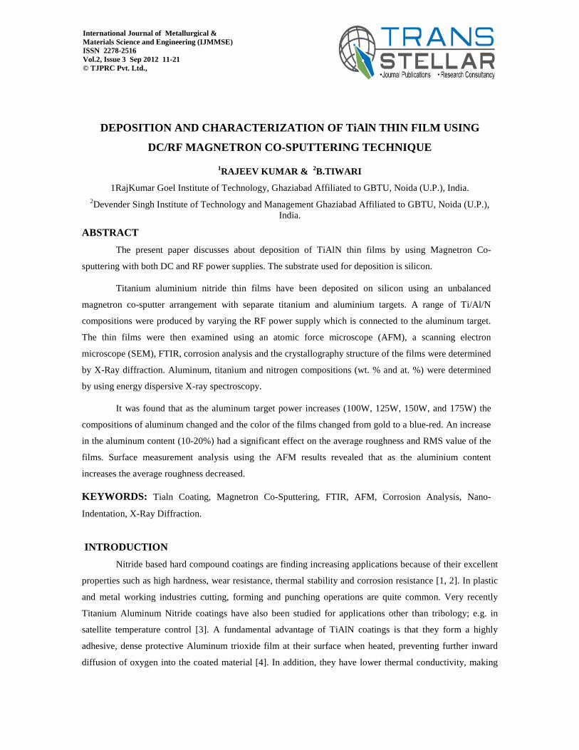
Three dimensional surface morphologies of TiAlN coatings deposited on silicon substrate for
different RF power are analyzed by using AFM images. For lower deposition RF power the grain size of the
film was large and films were fine. As the RF power increases the grain size of the film decreases and the
film obtained is lot finer. The colour of the films changed from golden to mouse gray colour. The roughness
of the films decreased as the RF power increased as shown in figure below
14 Rajeev Kumar & B.Tiwari
Figure 1. AFM images of sample 1, 2, 3 & 4
Table 2: RF power and average roughness
S.No. RF Power in Watt
Average Roughness in nm
Average RMS roughness value
in nm
1 100 30.815 168.532 2 125 12.127 103.325 3 150 4.751 13.582 4 175 2.325 3.142
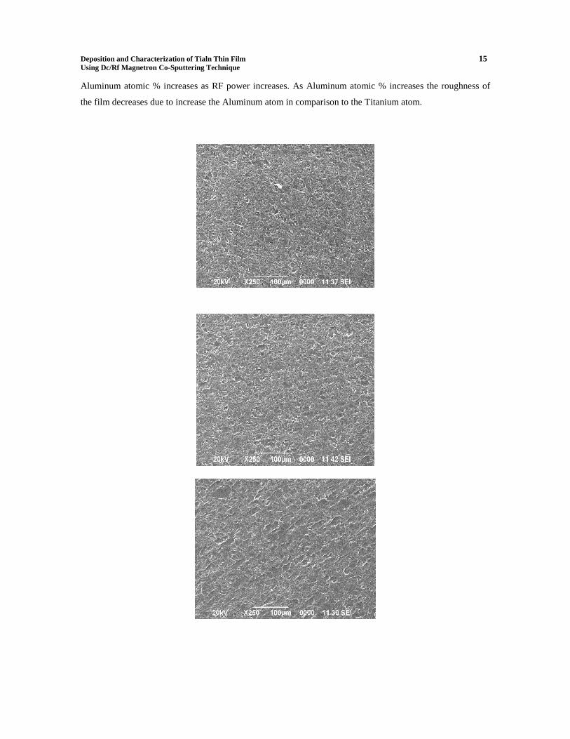
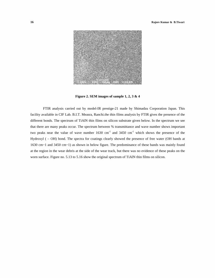
Scanning Electron Microscope analysis carried out by JSM-6390 LV, Jeol, Japan. In below Figures
we can see photographs of the microstructure of the samples from a scanning electron microscope, magnified
X 250 times. A smaller proportion of darker, irregular structures can be seen. In SEM analysis the picture for
the sample (1, 2, 3) looks like as same but in sample 4 some large black spot like as a cloud seeing. The
hardness of the sample 4 is larger in comparison to other samples because of Al At. % is much more.
Deposition and Characterization of Tialn Thin Film 15 Using Dc/Rf Magnetron Co-Sputtering Technique
Aluminum atomic % increases as RF power increases. As Aluminum atomic % increases the roughness of
the film decreases due to increase the Aluminum atom in comparison to the Titanium atom.
16 Rajeev Kumar & B.Tiwari
Figure 2. SEM images of sample 1, 2, 3 & 4
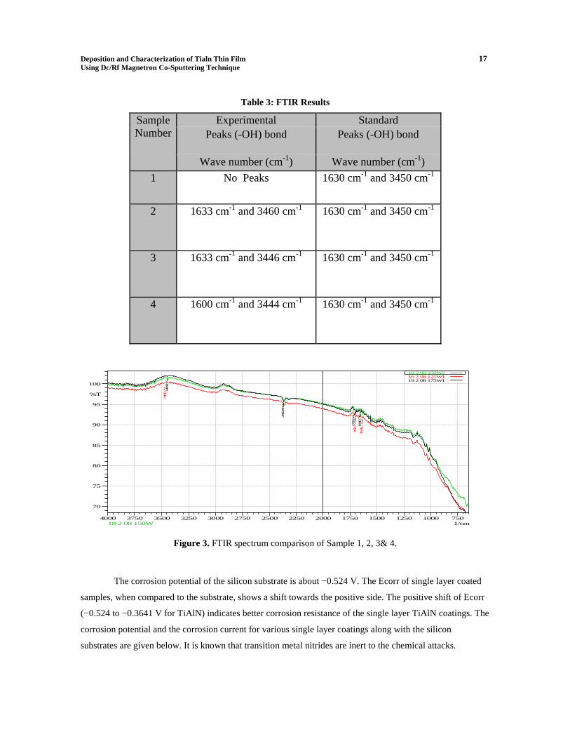
FTIR analysis carried out by model-IR prestige-21 made by Shimadzu Corporation Japan. This
facility available in CIF Lab. B.I.T. Measra, Ranchi.the thin films analysis by FTIR gives the presence of the
different bonds. The spectrum of TiAlN thin films on silicon substrate given below. In the spectrum we see
that there are many peaks occur. The spectrum between % transmittance and wave number shows important
two peaks near the value of wave number 1630 cm-1 and 3450 cm-1 which shows the presence of the
Hydroxyl ( – OH) bond. The spectra for coatings clearly showed the presence of free water (OH bands at
1630 cm−1 and 3450 cm−1) as shown in below figure. The predominance of these bands was mainly found
at the region in the wear debris at the side of the wear track, but there was no evidence of these peaks on the
worn surface. Figure no. 5.13 to 5.16 show the original spectrum of TiAlN thin films on silicon.
Deposition and Characterization of Tialn Thin Film 17 Using Dc/Rf Magnetron Co-Sputtering Technique
Table 3: FTIR Results
Sample Number
Experimental Standard Peaks (-OH) bond Peaks (-OH) bond
Wave number (cm-1) Wave number (cm-1)
1 No Peaks 1630 cm-1 and 3450 cm-1
2 1633 cm-1 and 3460 cm-1 1630 cm-1 and 3450 cm-1
3 1633 cm-1 and 3446 cm-1 1630 cm-1 and 3450 cm-1
4 1600 cm-1 and 3444 cm-1 1630 cm-1 and 3450 cm-1
75010001250150017502000225025002750300032503500375040001/cm
70
75
80
85
90
95
100
%T 3446.79
2362.80
1693.50
1633.71
3460.30
1695.43
1633.71
3444.87
2362.80
1703.14
1660.71
18 2 08 150W216 2 08 125W119 2 08 175W1
18 2 08 150W
Figure 3. FTIR spectrum comparison of Sample 1, 2, 3& 4.
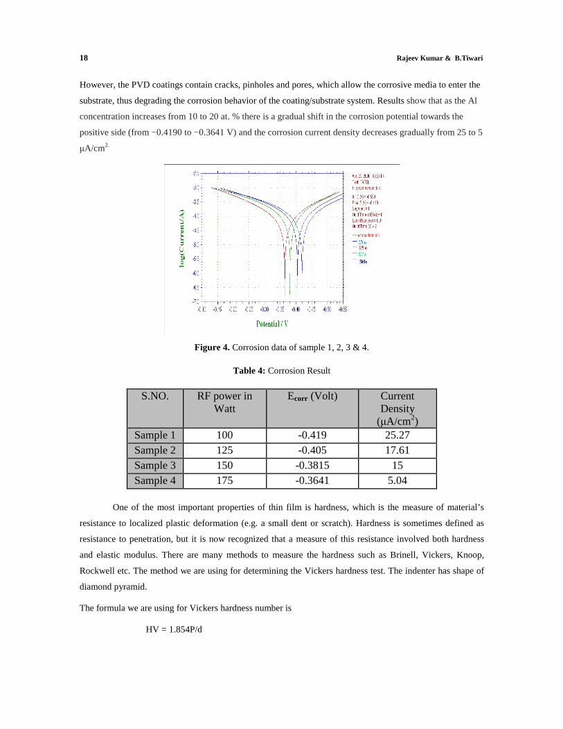
The corrosion potential of the silicon substrate is about −0.524 V. The Ecorr of single layer coated
samples, when compared to the substrate, shows a shift towards the positive side. The positive shift of Ecorr
(−0.524 to −0.3641 V for TiAlN) indicates better corrosion resistance of the single layer TiAlN coatings. The
corrosion potential and the corrosion current for various single layer coatings along with the silicon
substrates are given below. It is known that transition metal nitrides are inert to the chemical attacks.
18 Rajeev Kumar & B.Tiwari
However, the PVD coatings contain cracks, pinholes and pores, which allow the corrosive media to enter the
substrate, thus degrading the corrosion behavior of the coating/substrate system. Results show that as the Al
concentration increases from 10 to 20 at. % there is a gradual shift in the corrosion potential towards the
positive side (from −0.4190 to −0.3641 V) and the corrosion current density decreases gradually from 25 to 5
µA/cm2.
Figure 4. Corrosion data of sample 1, 2, 3 & 4.
Table 4: Corrosion Result
S.NO. RF power in
Watt Ecorr (Volt) Current
Density (µA/cm2)
Sample 1 100 -0.419 25.27 Sample 2 125 -0.405 17.61 Sample 3 150 -0.3815 15 Sample 4 175 -0.3641 5.04
One of the most important properties of thin film is hardness, which is the measure of material’s
resistance to localized plastic deformation (e.g. a small dent or scratch). Hardness is sometimes defined as
resistance to penetration, but it is now recognized that a measure of this resistance involved both hardness
and elastic modulus. There are many methods to measure the hardness such as Brinell, Vickers, Knoop,
Rockwell etc. The method we are using for determining the Vickers hardness test. The indenter has shape of
diamond pyramid.
The formula we are using for Vickers hardness number is
HV = 1.854P/d
Deposition and Characterization of Tialn Thin Film 19 Using Dc/Rf Magnetron Co-Sputtering Technique
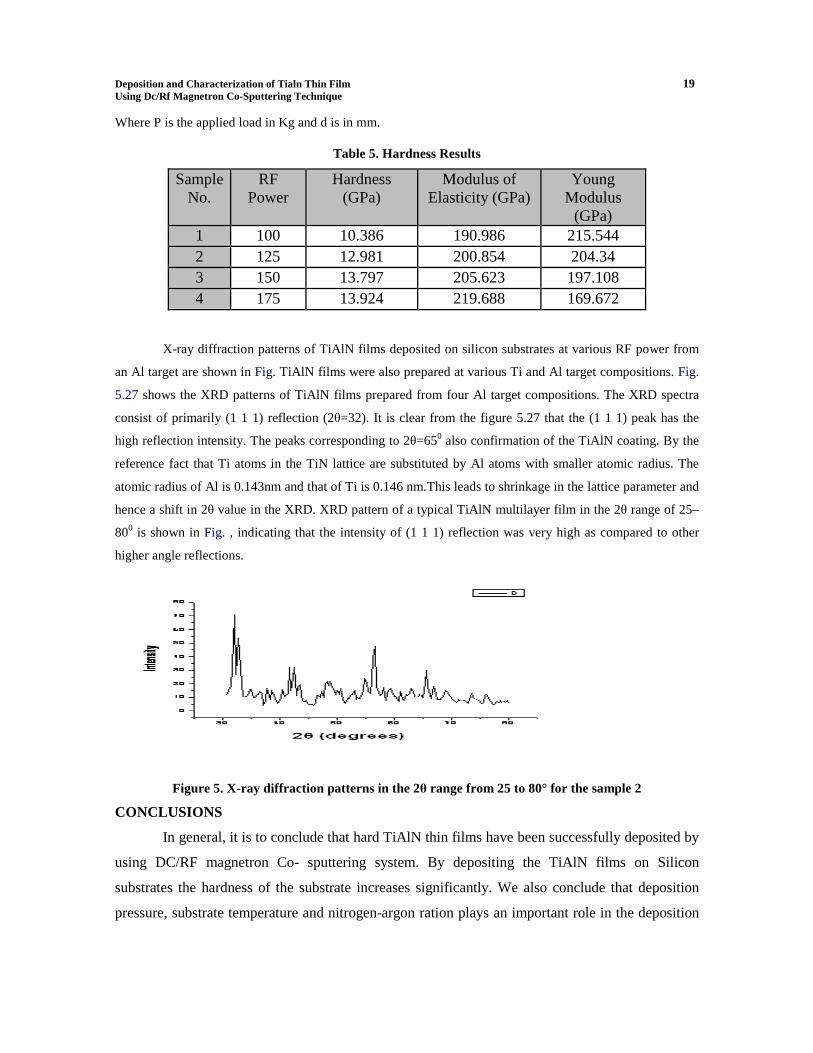
Where P is the applied load in Kg and d is in mm.
Table 5. Hardness Results
Sample No.
RF Power
Hardness (GPa)
Modulus of Elasticity (GPa)
Young Modulus
(GPa) 1 100 10.386 190.986 215.544 2 125 12.981 200.854 204.34 3 150 13.797 205.623 197.108 4 175 13.924 219.688 169.672
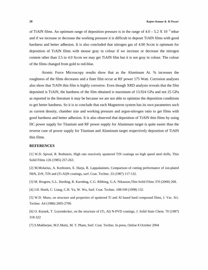
X-ray diffraction patterns of TiAlN films deposited on silicon substrates at various RF power from
an Al target are shown in Fig. TiAlN films were also prepared at various Ti and Al target compositions. Fig.
5.27 shows the XRD patterns of TiAlN films prepared from four Al target compositions. The XRD spectra
consist of primarily (1 1 1) reflection (2θ=32). It is clear from the figure 5.27 that the (1 1 1) peak has the
high reflection intensity. The peaks corresponding to 2θ=650 also confirmation of the TiAlN coating. By the
reference fact that Ti atoms in the TiN lattice are substituted by Al atoms with smaller atomic radius. The
atomic radius of Al is 0.143nm and that of Ti is 0.146 nm.This leads to shrinkage in the lattice parameter and
hence a shift in 2θ value in the XRD. XRD pattern of a typical TiAlN multilayer film in the 2θ range of 25–
800 is shown in Fig. , indicating that the intensity of (1 1 1) reflection was very high as compared to other
higher angle reflections.
Figure 5. X-ray diffraction patterns in the 2θ range from 25 to 80° for the sample 2
CONCLUSIONS
In general, it is to conclude that hard TiAlN thin films have been successfully deposited by
using DC/RF magnetron Co- sputtering system. By depositing the TiAlN films on Silicon
substrates the hardness of the substrate increases significantly. We also conclude that deposition
pressure, substrate temperature and nitrogen-argon ration plays an important role in the deposition
20 Rajeev Kumar & B.Tiwari
of TiAlN films. An optimum range of deposition pressure is in the range of 4.0 – 5.2 X 10 -2 mbar
and if we increase or decrease the working pressure it is difficult to deposit TiAlN films with good
hardness and better adhesion. It is also concluded that nitrogen gas of 4.00 Sccm is optimum for
deposition of TiAlN films with mouse gray in colour if we increase or decrease the nitrogen
content other than 3.5 to 4.0 Sccm we may get TiAlN film but it is not gray in colour. The colour
of the films changed from gold to red-blue.
Atomic Force Microscopy results show that as the Aluminum At. % increases the
roughness of the films decreases and a finer film occur at RF power 175 Watt. Corrosion analyses
also show that TiAlN thin film is highly corrosive. Even though XRD analysis reveals that the film
deposited is TiAlN, the hardness of the film obtained is maximum of 13.924 GPa and not 25 GPa
as reported in the literature it may be because we are not able to optimize the deposition conditions
to get better hardness. So it is to conclude that each Magnetron system has its own parameters such
as current density, chamber size and working pressure and argon-nitrogen ratio to get films with
good hardness and better adhesion. It is also observed that deposition of TiAlN thin films by using
DC power supply for Titanium and RF power supply for Aluminum target is quite easier than the
reverse case of power supply for Titanium and Aluminum target respectively deposition of TiAlN
thin films.
REFERENCES [1] W.D. Sproul, R. Rothstein, High rate reactively sputtered TiN coatings on high speed steel drills, Thin
Solid Films 126 (1985) 257-263.
[2] M.Molarius, A. Korhonen, E. Harju, R. Lappalaninen, Comparison of cutting performance of ion-plated
NbN, ZrN, TiN and (Ti-Al)N coatings, surf. Coat. Techno. 33 (1987) 117-132.
[3] M. Brogren, G.L. Harding, R. Karmhag, C.G. Ribbing, G.A. Nikasson,Thin Solid Films 370 (2000) 268.
[4] J.H. Hsieh, C. Liang, C.H. Yu, W. Wu, Surf. Coat. Techno. 108/109 (1998) 132.
[5] W.D. Munz, on structure and properties of sputtered Ti and Al based hard compound films, J. Vac. Sci.
Techno. A4 (1986) 2695-2700.
[6] O. Knotek, T. Leyendecker, on the structure of (Ti, Al) N-PVD coatings, J. Solid State Chem. 70 (1987)
318-322
[7] S.Mukherjee, M.F.Maitz, M. T. Pham, Surf. Coat. Techno. In press, Online 8 October 2004
Deposition and Characterization of Tialn Thin Film 21 Using Dc/Rf Magnetron Co-Sputtering Technique
[8] S. Rossi, L. Fedrizzi, M. Leoni, P. Scardi, Y. Massiani, (Ti,Cr)N and Ti/TiN PVD coating on 304
stainless steel substrates; wear-corrosion behavior , Thin Solid Films 350 (1-2) (1999) 161-167.
[9] W. R. Grove, Phil. Trans. Roy. Soc., London A 142, 87 (1852)
[10] Munz WD.J Vac Sci Techno 1986; A4: 2717.
[11] Knotek O, Munz WD, Leyendecker T.J Vac Sci Techno 1987; A5: 2173.
[12] M. Nose, T. Nagae, M. Yokota, S. Saji, M. Zhou, M. Nakada, Surf. Coat. Techno. 119 (1999) 296.
[13] C.P. Constable, D.B. Lewis, J. Yarwood, W. -D. Munz, Surf. Coat. Techno.
184 (2004) 291
[14] L. Karlsson, L. Hultman, J. -E. Sundgren, Thin Solid Films 371 (2000) 167.
[15] L. Cunha, M. Andritschky, L. Rebouta, R. Silva, Thin Solid Films 317 (1998)
351.