description of iec 61850 communication · iec 61850-7-1: principles and models iec 61850-7-2:...
TRANSCRIPT
01 02 03/1
Description of IEC 61850
Communication
Technical Report
Petr Matoušek
Technical Report no. FIT-TR-2018-01
Faculty of Information Technology
Brno University of Technology
Brno, Czech Republic
September, 2018
Last update: Feb 2019
© 2018, Brno University of Technology
2
Abstract IEC 61850 is a new international standard for communication of industrial communication systems (ICSs), especially in electric power system. The standard describes the system using abstract objects (logical nodes, data objects) that are accessed via Abstract Communication Service Interface (ACSI). The communication between devices and control station is designed as the client-server communication using Manufacturing Message Specification (MMS) protocol or via peer-to-peer system using Generic Object-Oriented Substation Event (GOOSE) protocol. This document describes the abstract model of the system as recommended by IEC 61850 standard
and also both communication protocols GOOSE and MMS. Intention of this paper is to focus on
security monitoring, thus detailed description of both protocol is present.
© 2018, Brno University of Technology
3
Table of Contents Abstract ......................................................................................................................................................... 2
1 Introduction................................................................................................................................................ 4
2 IEC 61850 Standard .................................................................................................................................... 5
2.1 IEC 61850 Information Model ............................................................................................................. 6
2.2 Abstract Communication Service Interface (ACSI) ............................................................................ 11
2.3 Mapping Object reference and Data Attribute reference to MMS ................................................... 13
2.4 Communication profiles .................................................................................................................... 13
3 GOOSE Protocol ........................................................................................................................................ 16
3.1 GOOSE Message Format ................................................................................................................... 16
3.2 Communication ................................................................................................................................. 19
3.3 Examples of Message Parsing ........................................................................................................... 21
3.4 GOOSE datasets ................................................................................................................................ 23
3.5 Summary ........................................................................................................................................... 26
4 MMS Protocol ........................................................................................................................................... 27
4.1 VMD model and MMS objects .......................................................................................................... 27
4.2 MMS Encapsulation .......................................................................................................................... 29
4.3 MMS Protocol ................................................................................................................................... 41
4.4 Example of MMS Communication ..................................................................................................... 52
4.5 Summary ........................................................................................................................................... 58
References ................................................................................................................................................... 60
Appendix A: IEC 61850 Logical Node Groups and Classes ........................................................................... 61
Appendix B: Common Data Classes (CDC) ................................................................................................... 62
Appendix C: Attribute Types and Functional Constraints ............................................................................ 63
Appendix D: Data Types .............................................................................................................................. 65
Appendix E: Mapping IEC 61850 objects and services to MMS ................................................................... 66
Appendix F: Application protocol specification for GOOSE ......................................................................... 67
Appendix G: ASN.1 and BER Encoding ......................................................................................................... 69
Appendix H: ACSE APDU .............................................................................................................................. 72
Appendix I: Format of Presentation Protocol Data Units (PPDUs)............................................................... 74
Appendix J: Format of MMS Protocol Data Units ........................................................................................ 76
© 2018, Brno University of Technology
4
1 Introduction Existing serial-based SCADA systems running on Modbus, IEC 60870-5-101, or DNP3 are not equipped enough to support next-generation capabilities of modern Intelligent Electronic Devices (IEDs). Even with IP-based protocol translation services, they lack deployment flexibility and ultimately rely on aging serial communications at the RTU. In an effort to modernize substation communication and leverage protocols that can take advantage of Ethernet and IP, the IEC Technical Committed 57 developed the IEC 61850 standard. IEC 61850 is an international standard defining communication protocols for intelligent electronic devices at electrical substations. It is a part of the International Electrotechnical Commission's (IEC) Technical Committee 57 reference architecture for electric power systems. The abstract data models defined in IEC 61850 can be mapped to a number of protocols. Current mappings in the standard are to MMS (Manufacturing Message Specification), GOOSE (Generic Object Oriented Substation Event), or SMV (Sampled Measured Values):
MMS protocol (IEC 61850-8-1) supports client/server communications over IP and is used for SCADA. It is used for monitoring purposes.
GOOSE (IEC 61850-8-1) uses Ethernet-based multicast (one-to-many) communications in which IEDs can communicate with each other and between bays. GOOSE is of the used for passing power measurements and between protection relays, as well as for tripping and interlocking circuits. It is used for status updates and sending command requests.
Sampled Measured Values (IEC 61850-9-2) carry power line current and voltage values. A common use for SMVs is for bus-bar protection and synchrophasors1.
These protocols can run over TCP/IP networks or substation LANs using high speed switched Ethernet to obtain the necessary response times below four milliseconds for protective relaying. The IEC 61850 protocol enables the integration of all protection, control, measurement and monitoring functions by one common protocol. It provides the means of high-speed substation applications, station wide interlocking and other functions which needs intercommunication between IEDs. The well described data modelling, the specified communication services for the most recent tasks in a station makes the standard to a key element in modern substation systems.
1 Synchrophasors are time-synchronized electrical numbers that monitor phase and power. They are measured by devices called phase measurement units (PMUs) in the substation [4].
© 2018, Brno University of Technology
5
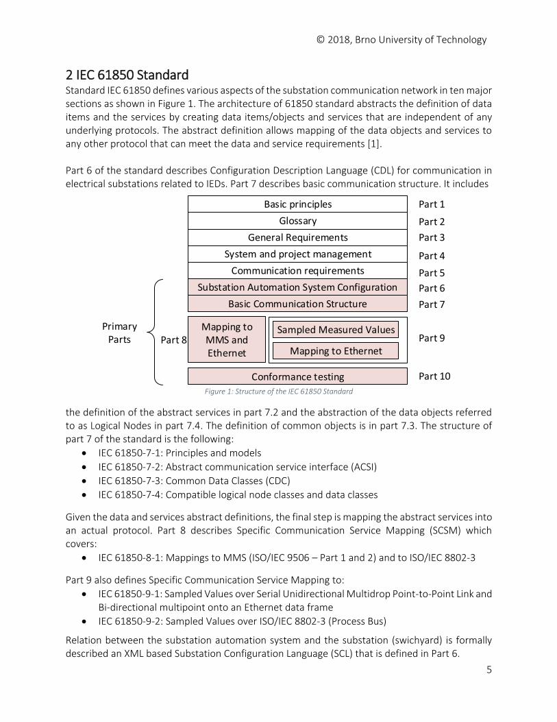
2 IEC 61850 Standard Standard IEC 61850 defines various aspects of the substation communication network in ten major sections as shown in Figure 1. The architecture of 61850 standard abstracts the definition of data items and the services by creating data items/objects and services that are independent of any underlying protocols. The abstract definition allows mapping of the data objects and services to any other protocol that can meet the data and service requirements [1]. Part 6 of the standard describes Configuration Description Language (CDL) for communication in electrical substations related to IEDs. Part 7 describes basic communication structure. It includes
Basic principles
Glossary
General Requirements
System and project management
Communication requirements
Substation Automation System Configuration
Basic Communication Structure
Mapping to MMS and Ethernet
Sampled Measured Values
Mapping to Ethernet
Conformance testing
Part 1
Part 2
Part 3
Part 4
Part 5
Part 6
Part 7
Part 8 Part 9
Part 10
PrimaryParts
Figure 1: Structure of the IEC 61850 Standard
the definition of the abstract services in part 7.2 and the abstraction of the data objects referred to as Logical Nodes in part 7.4. The definition of common objects is in part 7.3. The structure of part 7 of the standard is the following:
IEC 61850-7-1: Principles and models
IEC 61850-7-2: Abstract communication service interface (ACSI)
IEC 61850-7-3: Common Data Classes (CDC)
IEC 61850-7-4: Compatible logical node classes and data classes
Given the data and services abstract definitions, the final step is mapping the abstract services into an actual protocol. Part 8 describes Specific Communication Service Mapping (SCSM) which covers:
IEC 61850-8-1: Mappings to MMS (ISO/IEC 9506 – Part 1 and 2) and to ISO/IEC 8802-3
Part 9 also defines Specific Communication Service Mapping to:
IEC 61850-9-1: Sampled Values over Serial Unidirectional Multidrop Point-to-Point Link and Bi-directional multipoint onto an Ethernet data frame
IEC 61850-9-2: Sampled Values over ISO/IEC 8802-3 (Process Bus)
Relation between the substation automation system and the substation (swichyard) is formally described an XML based Substation Configuration Language (SCL) that is defined in Part 6.
© 2018, Brno University of Technology
6
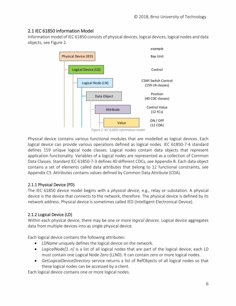
2.1 IEC 61850 Information Model Information model of IEC 61850 consists of physical devices, logical devices, logical nodes and data objects, see Figure 2.
Physical Device (IED)
Logical Device (LD)
Logical Node (LN)
Data Object
Attribute
Value
Bay Unit
Control
CSWI Switch Control(159 LN classes)
Position(40 CDC classes)
Control Value(12 FCs)
ON / OFF(12 CDA)
example
Figure 2: IEC 61850 information model
Physical device contains various functional modules that are modelled as logical devices. Each logical device can provide various operations defined as logical nodes. IEC 61850-7-4 standard defines 159 unique logical node classes. Logical nodes contain data objects that represent application functionality. Variables of a logical nodes are represented as a collection of Common Data Classes. Standard IEC 61850-7-3 defines 40 different CDCs, see Appendix B. Each data object contains a set of elements called data attributes that belong to 12 functional constraints, see Appendix C3. Attributes contains values defined by Common Data Attribute (CDA).
2.1.1 Physical Device (PD) The IEC 61850 device model begins with a physical device, e.g., relay or substation. A physical device is the device that connects to the network, therefore. The physical device is defined by its network address. Physical device is sometimes called IED (Intelligent Electronical Device).
2.1.2 Logical Device (LD) Within each physical device, there may be one or more logical devices. Logical device aggregates data from multiple devices into as single physical device. Each logical device contains the following attributes:
LDName uniquely defines the logical device on the network.
LogicalNode[1..n] is a list of all logical nodes that are part of the logical device; each LD must contain one Logical Node Zero (LLN0). It can contain zero or more logical nodes.
GetLogicalDeviceDirectory service returns a list of RefObjects of all logical nodes so that these logical nodes can be accessed by a client.
Each logical device contains one or more logical nodes.
© 2018, Brno University of Technology
7
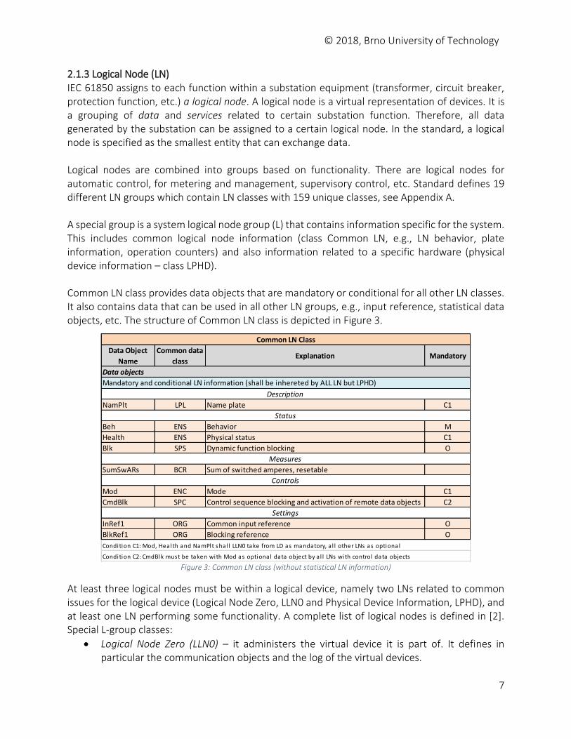
2.1.3 Logical Node (LN) IEC 61850 assigns to each function within a substation equipment (transformer, circuit breaker, protection function, etc.) a logical node. A logical node is a virtual representation of devices. It is a grouping of data and services related to certain substation function. Therefore, all data generated by the substation can be assigned to a certain logical node. In the standard, a logical node is specified as the smallest entity that can exchange data. Logical nodes are combined into groups based on functionality. There are logical nodes for automatic control, for metering and management, supervisory control, etc. Standard defines 19 different LN groups which contain LN classes with 159 unique classes, see Appendix A. A special group is a system logical node group (L) that contains information specific for the system. This includes common logical node information (class Common LN, e.g., LN behavior, plate information, operation counters) and also information related to a specific hardware (physical device information – class LPHD). Common LN class provides data objects that are mandatory or conditional for all other LN classes. It also contains data that can be used in all other LN groups, e.g., input reference, statistical data objects, etc. The structure of Common LN class is depicted in Figure 3.
Figure 3: Common LN class (without statistical LN information)
At least three logical nodes must be within a logical device, namely two LNs related to common issues for the logical device (Logical Node Zero, LLN0 and Physical Device Information, LPHD), and at least one LN performing some functionality. A complete list of logical nodes is defined in [2]. Special L-group classes:
Logical Node Zero (LLN0) – it administers the virtual device it is part of. It defines in particular the communication objects and the log of the virtual devices.
Data Object
Name
Common data
classExplanation Mandatory
NamPlt LPL Name plate C1
Beh ENS Behavior M
Health ENS Physical status C1
Blk SPS Dynamic function blocking O
SumSwARs BCR Sum of switched amperes, resetable
Mod ENC Mode C1
CmdBlk SPC Control sequence blocking and activation of remote data objects C2
InRef1 ORG Common input reference O
BlkRef1 ORG Blocking reference O
Controls
Settings
Mandatory and conditional LN information (shall be inhereted by ALL LN but LPHD)
Condition C1: Mod, Health and NamPlt shal l LLN0 take from LD as mandatory, a l l other LNs as optional
Condition C2: CmdBlk must be taken with Mod as optional data object by a l l LNs with control data objects
Common LN Class
Data objects
Description
Status
Measures
© 2018, Brno University of Technology
8
Physical Device Logical Node (LPHD1) – it represents the physical device, and in particular its communication properties, that are identical for all Logical Devices.
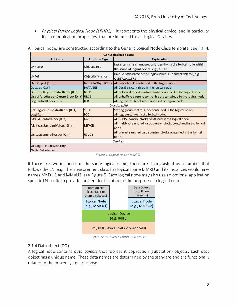
All logical nodes are constructed according to the Generic Logical Node Class template, see Fig. 4.
Figure 4: Logical Node Model [3]
If there are two instances of the same logical name, there are distinguished by a number that follows the LN, e.g., the measurement class has logical name MMXU and its instances would have names MMXU1 and MMXU2, see Figure 5. Each logical node may also use an optional application specific LN-prefix to provide further identification of the purpose of a logical node.
Logical Device (e.g. Relay)
Physical Device (Network Address)
Logical Node (e.g., MMXU1)
Logical Node (e.g., MMXU2)
Data Object(e.g. Phase to
ground voltages)
Data Object(e.g. Phase currents)
Figure 5: IEC 61850 Information Model
2.1.4 Data object (DO) A logical node contains data objects that represent application (substation) objects. Each data object has a unique name. These data names are determined by the standard and are functionally related to the power system purpose.
Attribute Attribute Type Explanation
LNName ObjectNameInstance name unambiguously identifying the logical node within
the scope of logical device, e.g., XCBR1
LNRef ObjectReferenceUnique path-name of the logical node: LDName/LNName, e.g.,
Q1B1W2/XCBR1
DataObject [1..n] GenDataObjectClass All data objects contained in the logical node.
DataSet [0..n] DATA-SET All DataSets contained in the logical node.
BufferedReportControlBlock [0..n] BRCB All buffered report control blocks contained in the logical node.
UnbufferedReportControlBlock [0..n] URCB All unbuffered report control blocks contained in the logical node.
LogControlBlocks [0..n] LCB All log control blocks contained in the logical node.
SettingGroupsControlBlock [0..1] SGCB Setting group control block contained in the logical node.
Log [0..n] LOG All logs contained in the logical node.
GOOSEControlBlock [0..n] GoCB All GOOSE control blocks contained in the logical node.
MulticastSampledValues [0..n] MSVCBAll multicast sampled value control blocks contained in the logical
node.
UnicastSampledValues [0..n] USVCBAll unicast sampled value control blocks contained in the logical
node.
GetAllDataValues
GenLogicalNode class
Only for LLN0
Services
GetLogicalNodeDirectory
© 2018, Brno University of Technology
9
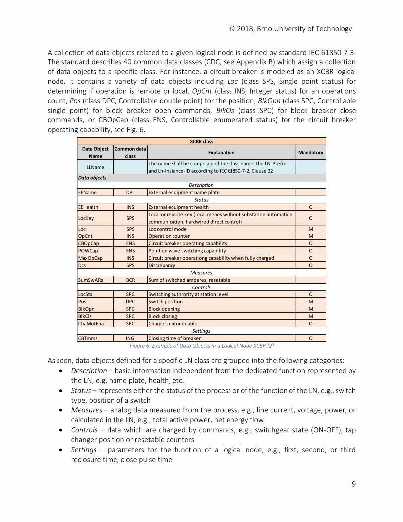
A collection of data objects related to a given logical node is defined by standard IEC 61850-7-3. The standard describes 40 common data classes (CDC, see Appendix B) which assign a collection of data objects to a specific class. For instance, a circuit breaker is modeled as an XCBR logical node. It contains a variety of data objects including Loc (class SPS, Single point status) for determining if operation is remote or local, OpCnt (class INS, Integer status) for an operations count, Pos (class DPC, Controllable double point) for the position, BlkOpn (class SPC, Controllable single point) for block breaker open commands, BlkCls (class SPC) for block breaker close commands, or CBOpCap (class ENS, Controllable enumerated status) for the circuit breaker operating capability, see Fig. 6.
Figure 6: Example of Data Objects in a Logical Node XCBR [2]
As seen, data objects defined for a specific LN class are grouped into the following categories:
Description – basic information independent from the dedicated function represented by the LN, e.g, name plate, health, etc.
Status – represents either the status of the process or of the function of the LN, e.g., switch type, position of a switch
Measures – analog data measured from the process, e.g., line current, voltage, power, or calculated in the LN, e.g., total active power, net energy flow
Controls – data which are changed by commands, e.g., switchgear state (ON-OFF), tap changer position or resetable counters
Settings – parameters for the function of a logical node, e.g., first, second, or third reclosure time, close pulse time
Data Object
Name
Common data
classExplanation Mandatory
LLNameThe name shall be composed of the class name, the LN-Prefix
and Ln-Instance-ID according to IEC 61850-7-2, Clause 22
EEName DPL External equipment name plate
EEHealth INS External equipment health O
LocKey SPSLocal or remote key (local means without substation automation
communication, hardwired direct control)O
Loc SPS Loc control mode M
OpCnt INS Operation counter M
CBOpCap ENS Circuit breaker operating capability O
POWCap ENS Point on wave switching capability O
MaxOpCap INS Circuit breaker operationg capability when fully charged O
Dcs SPS Discrepancy O
SumSwARs BCR Sum of switched amperes, resetable
LocSta SPC Switching authrority at station level O
Pos DPC Switch position M
BlkOpn SPC Block opening M
BlkCls SPC Block closing M
ChaMotEna SPC Charger motor enable O
CBTmms ING Closing time of breaker O
XCBR class
Controls
Measures
Settings
Data objects
Description
Status
© 2018, Brno University of Technology
10
Standard 61850-7-2 also defines which data objects are mandatory (M), optional (O), or conditional (C) for a given logical node.
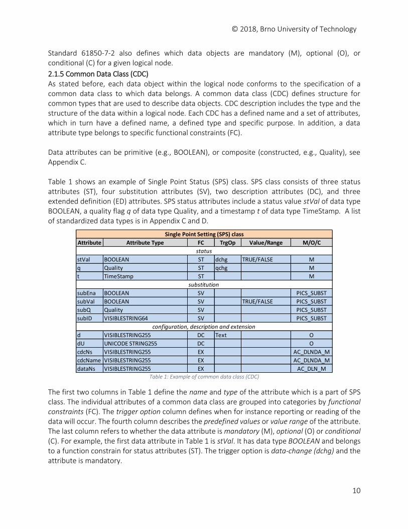
2.1.5 Common Data Class (CDC) As stated before, each data object within the logical node conforms to the specification of a common data class to which data belongs. A common data class (CDC) defines structure for common types that are used to describe data objects. CDC description includes the type and the structure of the data within a logical node. Each CDC has a defined name and a set of attributes, which in turn have a defined name, a defined type and specific purpose. In addition, a data attribute type belongs to specific functional constraints (FC). Data attributes can be primitive (e.g., BOOLEAN), or composite (constructed, e.g., Quality), see Appendix C. Table 1 shows an example of Single Point Status (SPS) class. SPS class consists of three status attributes (ST), four substitution attributes (SV), two description attributes (DC), and three extended definition (ED) attributes. SPS status attributes include a status value stVal of data type BOOLEAN, a quality flag q of data type Quality, and a timestamp t of data type TimeStamp. A list of standardized data types is in Appendix C and D.
Table 1: Example of common data class (CDC)
The first two columns in Table 1 define the name and type of the attribute which is a part of SPS class. The individual attributes of a common data class are grouped into categories by functional constraints (FC). The trigger option column defines when for instance reporting or reading of the data will occur. The fourth column describes the predefined values or value range of the attribute. The last column refers to whether the data attribute is mandatory (M), optional (O) or conditional (C). For example, the first data attribute in Table 1 is stVal. It has data type BOOLEAN and belongs to a function constrain for status attributes (ST). The trigger option is data-change (dchg) and the attribute is mandatory.
Attribute Attribute Type FC TrgOp Value/Range M/O/C
stVal BOOLEAN ST dchg TRUE/FALSE M
q Quality ST qchg M
t TimeStamp ST M
subEna BOOLEAN SV PICS_SUBST
subVal BOOLEAN SV TRUE/FALSE PICS_SUBST
subQ Quality SV PICS_SUBST
subID VISIBLESTRING64 SV PICS_SUBST
d VISIBLESTRING255 DC Text O
dU UNICODE STRING255 DC O
cdcNs VISIBLESTRING255 EX AC_DLNDA_M
cdcName VISIBLESTRING255 EX AC_DLNDA_M
dataNs VISIBLESTRING255 EX AC_DLN_M
Single Point Setting (SPS) class
substitution
status
configuration, description and extension
© 2018, Brno University of Technology
11
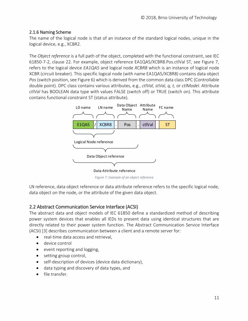
2.1.6 Naming Scheme The name of the logical node is that of an instance of the standard logical nodes, unique in the logical device, e.g., XCBR2. The Object reference is a full path of the object, completed with the functional constraint, see IEC 61850-7-2, clause 22. For example, object reference EA1QA5/XCBR8.Pos.ctlVal ST, see Figure 7, refers to the logical device EA1QA5 and logical node XCBR8 which is an instance of logical node XCBR (circuit breaker). This specific logical node (with name EA1QA5/XCBR8) contains data object Pos (switch position, see Figure 6) which is derived from the common data class DPC (Controllable double point). DPC class contains various attributes, e.g., ctlVal, stVal, q, t, or ctlModel. Attribute ctlVal has BOOLEAN data type with values FALSE (switch off) or TRUE (switch on). This attribute contains functional constraint ST (status attribute).
ST
LD name LN nameData Object
NameAttribute
Name FC name
Logical Node reference
Data Object reference
Data Attribute reference
E1QA5 XCBR8 Pos ctlVal/ . .
Figure 7: Example of an object reference
LN reference, data object reference or data attribute reference refers to the specific logical node, data object on the node, or the attribute of the given data object.
2.2 Abstract Communication Service Interface (ACSI) The abstract data and object models of IEC 61850 define a standardized method of describing power system devices that enables all IEDs to present data using identical structures that are directly related to their power system function. The Abstract Communication Service Interface (ACSI) [3] describes communication between a client and a remote server for:
real-time data access and retrieval,
device control
event reporting and logging,
setting group control,
self-description of devices (device data dictionary),
data typing and discovery of data types, and
file transfer.
© 2018, Brno University of Technology
12
ACSI also provide the abstract interface for fast and reliable system-wide event distribution between an application in one device and many remote applications in different devices (publisher/subscriber) and for transmission of sampled measured values. In the ACSI model there are two groups of communication services. The first group uses client-server model, e.g., getting data values from IEDs. The second group is a peer-to-peer model with Generic Substation Event (GSE) services which are used for fast communication between IEDs using GOOSE messages and periodic sampled value (SV) transmissions.
Client-server communication is a service where the client requests data from a server. The server contains the content of a logical device, the association model, time synchronization and file transfer. This client-server communication is used for transferring large amounts of data which are not time-critical.
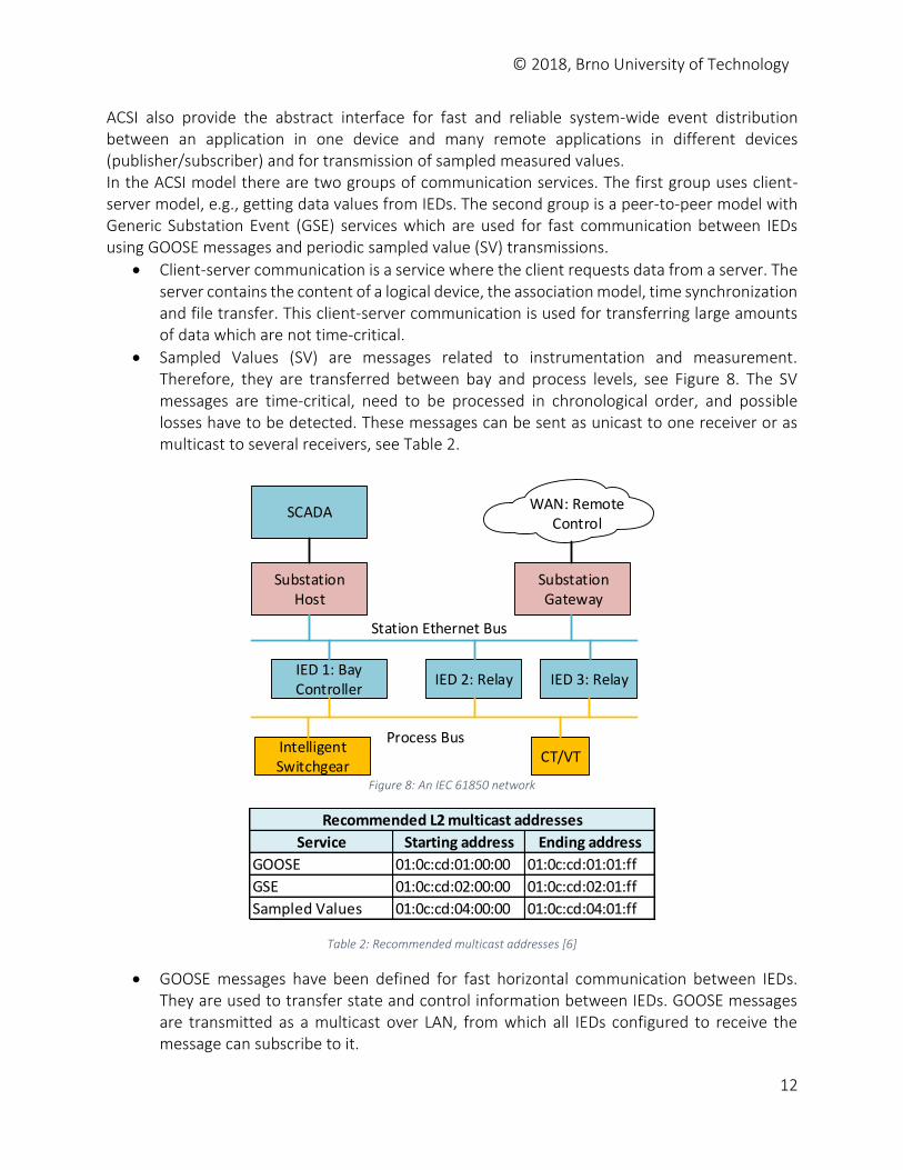
Sampled Values (SV) are messages related to instrumentation and measurement. Therefore, they are transferred between bay and process levels, see Figure 8. The SV messages are time-critical, need to be processed in chronological order, and possible losses have to be detected. These messages can be sent as unicast to one receiver or as multicast to several receivers, see Table 2.
SCADA
SubstationHost
IED 1: Bay Controller
IED 2: Relay IED 3: Relay
IntelligentSwitchgear
CT/VT
Station Ethernet Bus
Process Bus
SubstationGateway
WAN: Remote Control
Figure 8: An IEC 61850 network
Table 2: Recommended multicast addresses [6]
GOOSE messages have been defined for fast horizontal communication between IEDs. They are used to transfer state and control information between IEDs. GOOSE messages are transmitted as a multicast over LAN, from which all IEDs configured to receive the message can subscribe to it.
Service Starting address Ending address
GOOSE 01:0c:cd:01:00:00 01:0c:cd:01:01:ff
GSE 01:0c:cd:02:00:00 01:0c:cd:02:01:ff
Sampled Values 01:0c:cd:04:00:00 01:0c:cd:04:01:ff
Recommended L2 multicast addresses
© 2018, Brno University of Technology
13
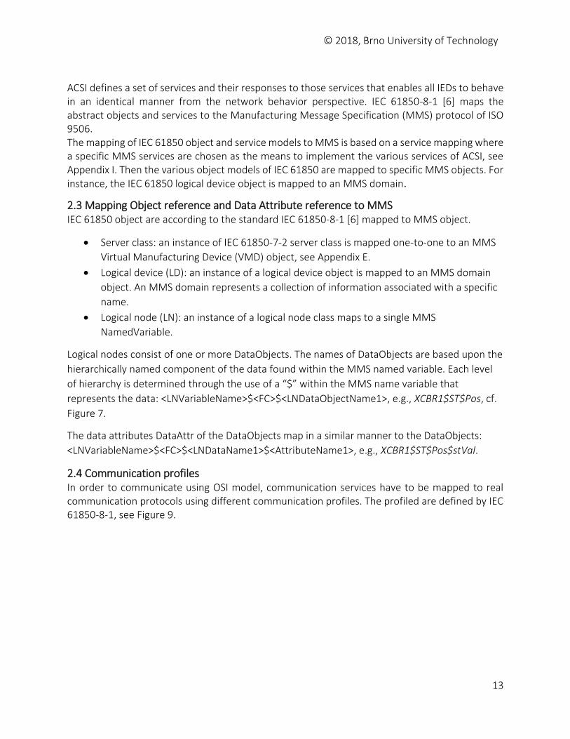
ACSI defines a set of services and their responses to those services that enables all IEDs to behave in an identical manner from the network behavior perspective. IEC 61850-8-1 [6] maps the abstract objects and services to the Manufacturing Message Specification (MMS) protocol of ISO 9506. The mapping of IEC 61850 object and service models to MMS is based on a service mapping where a specific MMS services are chosen as the means to implement the various services of ACSI, see Appendix I. Then the various object models of IEC 61850 are mapped to specific MMS objects. For instance, the IEC 61850 logical device object is mapped to an MMS domain.
2.3 Mapping Object reference and Data Attribute reference to MMS IEC 61850 object are according to the standard IEC 61850-8-1 [6] mapped to MMS object.
Server class: an instance of IEC 61850-7-2 server class is mapped one-to-one to an MMS
Virtual Manufacturing Device (VMD) object, see Appendix E.
Logical device (LD): an instance of a logical device object is mapped to an MMS domain
object. An MMS domain represents a collection of information associated with a specific
name.
Logical node (LN): an instance of a logical node class maps to a single MMS
NamedVariable.
Logical nodes consist of one or more DataObjects. The names of DataObjects are based upon the
hierarchically named component of the data found within the MMS named variable. Each level
of hierarchy is determined through the use of a “$” within the MMS name variable that
represents the data: <LNVariableName>$<FC>$<LNDataObjectName1>, e.g., XCBR1$ST$Pos, cf.
Figure 7.
The data attributes DataAttr of the DataObjects map in a similar manner to the DataObjects:
<LNVariableName>$<FC>$<LNDataName1>$<AttributeName1>, e.g., XCBR1$ST$Pos$stVal.
2.4 Communication profiles In order to communicate using OSI model, communication services have to be mapped to real communication protocols using different communication profiles. The profiled are defined by IEC 61850-8-1, see Figure 9.
© 2018, Brno University of Technology
14
SV PTP GOOSEMMS Protocol
SuiteSNTP
Sampled Values
(multicast)Time Sync Core ACSI Services
Generic Object Oriented Substation
Event
UDP
IP
UDP
IP
UDP
IP
TCP
IP
ISO/IEC 8802-3 Ethertype
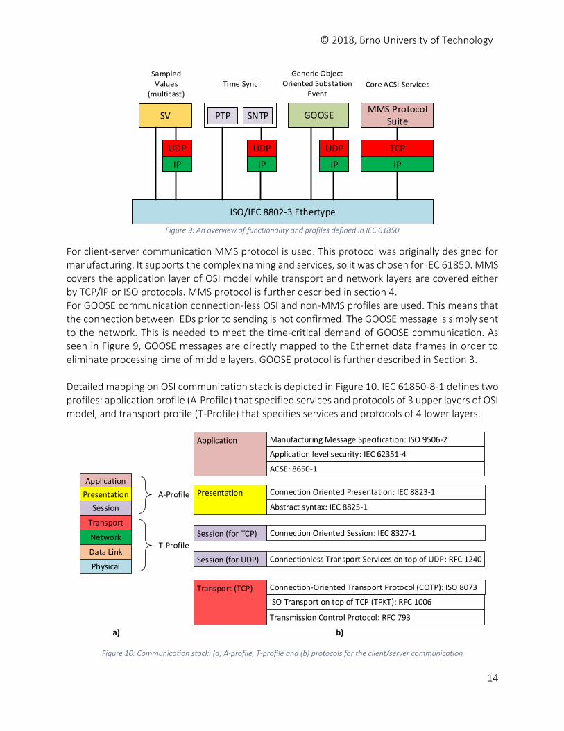
Figure 9: An overview of functionality and profiles defined in IEC 61850
For client-server communication MMS protocol is used. This protocol was originally designed for manufacturing. It supports the complex naming and services, so it was chosen for IEC 61850. MMS covers the application layer of OSI model while transport and network layers are covered either by TCP/IP or ISO protocols. MMS protocol is further described in section 4. For GOOSE communication connection-less OSI and non-MMS profiles are used. This means that the connection between IEDs prior to sending is not confirmed. The GOOSE message is simply sent to the network. This is needed to meet the time-critical demand of GOOSE communication. As seen in Figure 9, GOOSE messages are directly mapped to the Ethernet data frames in order to eliminate processing time of middle layers. GOOSE protocol is further described in Section 3. Detailed mapping on OSI communication stack is depicted in Figure 10. IEC 61850-8-1 defines two profiles: application profile (A-Profile) that specified services and protocols of 3 upper layers of OSI model, and transport profile (T-Profile) that specifies services and protocols of 4 lower layers.
Application
Presentation
Session
Transport
Network
Data Link
Physical
A-Profile
T-Profile
Application Manufacturing Message Specification: ISO 9506-2
Application level security: IEC 62351-4
ACSE: 8650-1
Presentation Connection Oriented Presentation: IEC 8823-1
Abstract syntax: IEC 8825-1
Session (for TCP) Connection Oriented Session: IEC 8327-1
Transport (TCP)
ISO Transport on top of TCP (TPKT): RFC 1006
Transmission Control Protocol: RFC 793
a) b)
Session (for UDP) Connectionless Transport Services on top of UDP: RFC 1240
Connection-Oriented Transport Protocol (COTP): ISO 8073
Figure 10: Communication stack: (a) A-profile, T-profile and (b) protocols for the client/server communication
© 2018, Brno University of Technology
15
Various combinations of A-Profiles and T-Profiles can be combined in order to allow certain types of information/services to be exchanged. The services, as specified in IEC 61850-7-2, are mapped into four different combinations of A- and T- profiles and are used for:
Client-server services (MMS),
GOOSE/GSE management services,
GSSE services, and
Time synchronization (PTP, SNTP). Protocols defined in A-profiles for MMS are mandatory except Application Layer Security (IEC 62351-4) which is conditional. A-profile for GOOSE requires RFC 1240 header on top of UDP. T-profile for MMS requires TPKT protocol on top of TCP when TCP is used which is typical for MMS. More details about MMS and GOOSE communication are mentioned in the following sections.
© 2018, Brno University of Technology
16
3 GOOSE Protocol Generic Object-Oriented Substation Event (GOOSE) protocol implements transfer of time-critical events such as protection of electrical equipment between IEC 61850 devices. IEC 61850 standard defines two groups of communication services: a client-server model and a peer-to-peer model. The peer-to-peer model is utilized for Generic Substation Event (GSE) services associated with time-critical activities such as fast and reliable communication between IEDs. One of the messages associated with the GSE services are GOOSE messages that allow for the broadcast or multicast messages across the LAN.
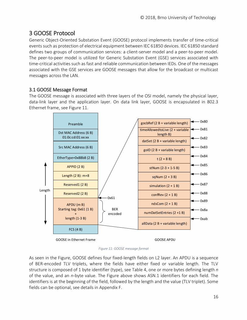
3.1 GOOSE Message Format The GOOSE message is associated with three layers of the OSI model, namely the physical layer, data-link layer and the application layer. On data link layer, GOOSE is encapsulated in 802.3 Ethernet frame, see Figure 11.
Preamble
Dst MAC Address (6 B)01:0c:cd:01:xx:xx
Src MAC Address (6 B)
EtherType=0x88b8 (2 B)
APPID (2 B)
Length (2 B): m+8
Reserved1 (2 B)
Reserved2 (2 B)
APDU (m B)Starting tag: 0x61 (1 B)
+ length (1-3 B)
FCS (4 B)
GOOSE in Ethernet Frame
gocbRef (2 B + variable length)
timeAllowedtoLive (2 + variable length B)
datSet (2 B + variable length)
goID (2 B + variable length)
t (2 + 8 B)
stNum (2-3 + 1-5 B)
sqNum (2 + 3 B)
simulation (2 + 1 B)
confRev (2 + 1 B)
ndsCom (2 + 1 B)
numDatSetEntries (2 +1 B)
allData (2 B + variable length)
GOOSE APDU
Length
0x61
0x80
0x81
0x82
0x83
0x84
0x85
0x86
0x87
0x88
0x89
0x8a
0xab
BER encoded
Figure 11: GOOSE message format
As seen in the Figure, GOOSE defines four fixed-length fields on L2 layer. An APDU is a sequence of BER-encoded TLV triplets, where the fields have either fixed or variable length. The TLV structure is composed of 1 byte identifier (type), see Table 4, one or more bytes defining length n of the value, and an n-byte value. The Figure above shows ASN.1 identifiers for each field. The identifiers is at the beginning of the field, followed by the length and the value (TLV triplet). Some fields can be optional, see details in Appendix F.
© 2018, Brno University of Technology
17
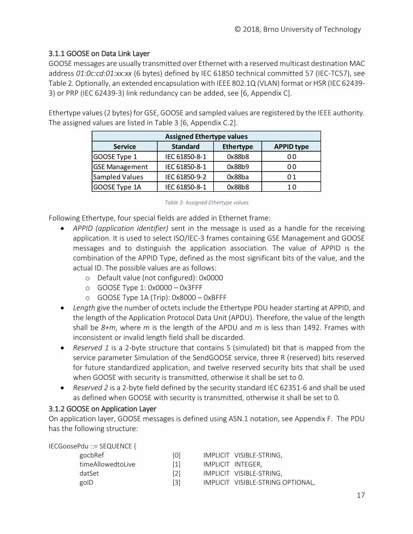
3.1.1 GOOSE on Data Link Layer GOOSE messages are usually transmitted over Ethernet with a reserved multicast destination MAC address 01:0c:cd:01:xx:xx (6 bytes) defined by IEC 61850 technical committed 57 (IEC-TC57), see Table 2. Optionally, an extended encapsulation with IEEE 802.1Q (VLAN) format or HSR (IEC 62439-3) or PRP (IEC 62439-3) link redundancy can be added, see [6, Appendix C]. Ethertype values (2 bytes) for GSE, GOOSE and sampled values are registered by the IEEE authority. The assigned values are listed in Table 3 [6, Appendix C.2].
Table 3: Assigned Ethertype values
Following Ethertype, four special fields are added in Ethernet frame:
APPID (application identifier) sent in the message is used as a handle for the receiving application. It is used to select ISO/IEC-3 frames containing GSE Management and GOOSE messages and to distinguish the application association. The value of APPID is the combination of the APPID Type, defined as the most significant bits of the value, and the actual ID. The possible values are as follows:
o Default value (not configured): 0x0000 o GOOSE Type 1: 0x0000 – 0x3FFF o GOOSE Type 1A (Trip): 0x8000 – 0xBFFF
Length give the number of octets include the Ethertype PDU header starting at APPID, and the length of the Application Protocol Data Unit (APDU). Therefore, the value of the length shall be 8+m, where m is the length of the APDU and m is less than 1492. Frames with inconsistent or invalid length field shall be discarded.
Reserved 1 is a 2-byte structure that contains S (simulated) bit that is mapped from the service parameter Simulation of the SendGOOSE service, three R (reserved) bits reserved for future standardized application, and twelve reserved security bits that shall be used when GOOSE with security is transmitted, otherwise it shall be set to 0.
Reserved 2 is a 2-byte field defined by the security standard IEC 62351-6 and shall be used as defined when GOOSE with security is transmitted, otherwise it shall be set to 0.
3.1.2 GOOSE on Application Layer On application layer, GOOSE messages is defined using ASN.1 notation, see Appendix F. The PDU has the following structure:
IECGoosePdu ::= SEQUENCE { gocbRef [0] IMPLICIT VISIBLE-STRING, timeAllowedtoLive [1] IMPLICIT INTEGER, datSet [2] IMPLICIT VISIBLE-STRING, goID [3] IMPLICIT VISIBLE-STRING OPTIONAL,
Service Standard Ethertype APPID type
GOOSE Type 1 IEC 61850-8-1 0x88b8 0 0
GSE Management IEC 61850-8-1 0x88b9 0 0
Sampled Values IEC 61850-9-2 0x88ba 0 1
GOOSE Type 1A IEC 61850-8-1 0x88b8 1 0
Assigned Ethertype values

© 2018, Brno University of Technology
18
T [4] IMPLICIT UtcTime, stNum [5] IMPLICIT INTEGER, sqNum [6] IMPLICIT INTEGER, simulation [7] IMPLICIT BOOLEAN DEFAULT FALSE, confRev [8] IMPLICIT INTEGER, ndsCom [9] IMPLICIT BOOLEAN DEFAULT FALSE, numDatSetEntries [10] IMPLICIT INTEGER, allData [11] IMPLICIT SEQUENCE OF Data, }
The structure of GOOSE PDU is derived from GOOSE Control Block object as defined by IEC 61850-7-2 standard [3]. It consists of the following items:
GoCBRef – GOOSE control block reference is a unique path-name of an instance of GOOSE Control Block (GoCB) within LLN0. The format is LDName/LLN0.GoCBName, e.g., GEDeviceF650/LLN0$GO$gcb01 where LD name is GEDeviceF650, LN class is LLN0 (Logical Node Zero), functional constraint is GO (GOOSE Control) and GoCB instance is gcb01.
TimeAllowedtoLive – time at which the attribute StNum was incremented. It informs subscribers of how long to wait for the next repetition of the message.
DatSet – references of the data set whose values of members shall be transmitted, e.g., GEDeviceF650/LLN0$GOOSE1. The members of the DataSet shall be uniquely numbered beginning with 1. This number is called the MemberOffset of a given member. Each member of the DataSet has a unique number and a MemberReference (the functional constraint data FCD or DataAttribute FCDA), see Figure 12.
GoID – GOOSE ID is an attribute that allows a user to assign an identification for the GOOSE message, e.g., F650_GOOSE1.
T (timestamp) – time at which the attribute StNum was incremented.
StNum (status number) is a counter that increments each time a GOOSE message has been sent and a value change has been detected within the DataSet specified by DatSet. The initital value shall be 1. The value 0 is reserved.
SqNum – is the current sequence number of the reports. It shall increment each time a GOOSE message sent. Following a StNum change, the counter SqNum shall be set to a value 0. The initial value for SqNum upon a transmission of GoEna to TRUE is 1. This number seems to be similar to the sequence number in TCP.
Simulation (test bit) – if true, the message and therefore its value have been issued by a simulation unit and are not real values. The GOOSE subscriber will report the value of the simulated message to its application instead of the real message depending on the setting of the receiving IED.
ConfRev – contains the configuration revision to indicate deletion of a member of the data set or the reordering of the members, or changing the DatSet reference. The number shall represent a count of the number of times that the configuration of the DataSet referenced by DatSet value has been changed.
NdsCom – indicates in the message that some commissioning is required (need commission). If TRUE, the GoCB requires further configuration.
NumDatSetEntries – a number of data set entries
allData – a list of user defined information of the MMS NamedVariableList that is specified in GOOSE control block.
© 2018, Brno University of Technology
19
3.2 Communication The generic substation event model provides the possibility for a fast and reliable system-wide distribution of input and output values. The generic substation event model is based on the concept of an autonomous decentralization, providing an efficient method allowing the simultaneous delivery of the same generic substation event information to more than one physical device through the use of multicast/broadcast services. Two control classes and the structure of two messages are defined by the IEC 61850-7-2 [3]:
Generic object oriented substation event (GOOSE) that supports the exchange of a wide range of possible common data organized by a data set,
Generic substation state event (GSSE) provides the capability to convey state exchange information (bit pairs).
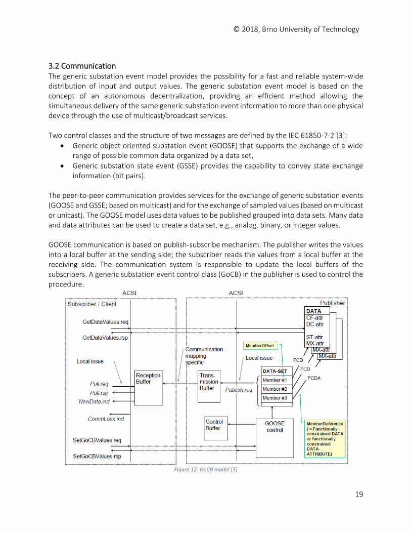
The peer-to-peer communication provides services for the exchange of generic substation events (GOOSE and GSSE; based on multicast) and for the exchange of sampled values (based on multicast or unicast). The GOOSE model uses data values to be published grouped into data sets. Many data and data attributes can be used to create a data set, e.g., analog, binary, or integer values. GOOSE communication is based on publish-subscribe mechanism. The publisher writes the values into a local buffer at the sending side; the subscriber reads the values from a local buffer at the receiving side. The communication system is responsible to update the local buffers of the subscribers. A generic substation event control class (GoCB) in the publisher is used to control the procedure.
Figure 12: GoCB model [3]
© 2018, Brno University of Technology
20
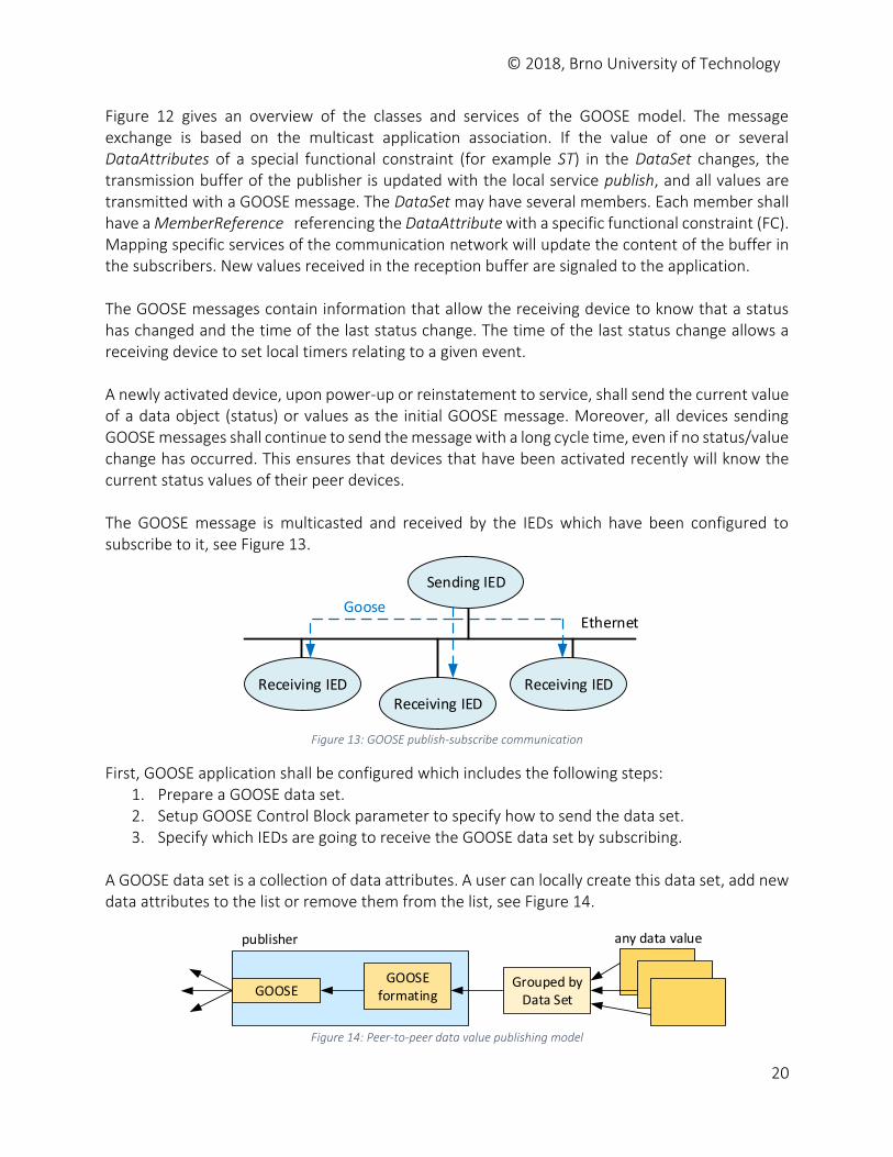
Figure 12 gives an overview of the classes and services of the GOOSE model. The message exchange is based on the multicast application association. If the value of one or several DataAttributes of a special functional constraint (for example ST) in the DataSet changes, the transmission buffer of the publisher is updated with the local service publish, and all values are transmitted with a GOOSE message. The DataSet may have several members. Each member shall have a MemberReference referencing the DataAttribute with a specific functional constraint (FC). Mapping specific services of the communication network will update the content of the buffer in the subscribers. New values received in the reception buffer are signaled to the application. The GOOSE messages contain information that allow the receiving device to know that a status has changed and the time of the last status change. The time of the last status change allows a receiving device to set local timers relating to a given event. A newly activated device, upon power-up or reinstatement to service, shall send the current value of a data object (status) or values as the initial GOOSE message. Moreover, all devices sending GOOSE messages shall continue to send the message with a long cycle time, even if no status/value change has occurred. This ensures that devices that have been activated recently will know the current status values of their peer devices. The GOOSE message is multicasted and received by the IEDs which have been configured to subscribe to it, see Figure 13.
Ethernet
Receiving IEDReceiving IED
Receiving IED
Sending IED
Goose
Figure 13: GOOSE publish-subscribe communication
First, GOOSE application shall be configured which includes the following steps: 1. Prepare a GOOSE data set. 2. Setup GOOSE Control Block parameter to specify how to send the data set. 3. Specify which IEDs are going to receive the GOOSE data set by subscribing.
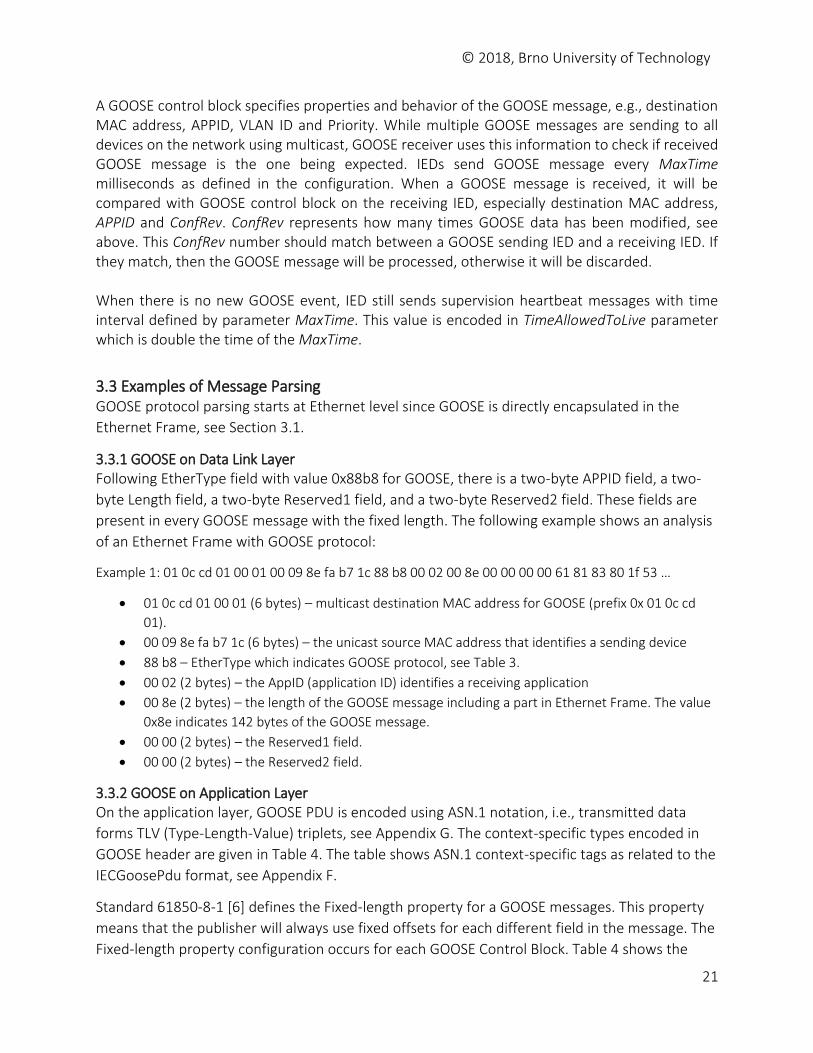
A GOOSE data set is a collection of data attributes. A user can locally create this data set, add new data attributes to the list or remove them from the list, see Figure 14.
GOOSEGOOSE
formatingGrouped by
Data Set
any data valuepublisher
Figure 14: Peer-to-peer data value publishing model
© 2018, Brno University of Technology
21
A GOOSE control block specifies properties and behavior of the GOOSE message, e.g., destination MAC address, APPID, VLAN ID and Priority. While multiple GOOSE messages are sending to all devices on the network using multicast, GOOSE receiver uses this information to check if received GOOSE message is the one being expected. IEDs send GOOSE message every MaxTime milliseconds as defined in the configuration. When a GOOSE message is received, it will be compared with GOOSE control block on the receiving IED, especially destination MAC address, APPID and ConfRev. ConfRev represents how many times GOOSE data has been modified, see above. This ConfRev number should match between a GOOSE sending IED and a receiving IED. If they match, then the GOOSE message will be processed, otherwise it will be discarded. When there is no new GOOSE event, IED still sends supervision heartbeat messages with time interval defined by parameter MaxTime. This value is encoded in TimeAllowedToLive parameter which is double the time of the MaxTime.
3.3 Examples of Message Parsing GOOSE protocol parsing starts at Ethernet level since GOOSE is directly encapsulated in the
Ethernet Frame, see Section 3.1.
3.3.1 GOOSE on Data Link Layer Following EtherType field with value 0x88b8 for GOOSE, there is a two-byte APPID field, a two-
byte Length field, a two-byte Reserved1 field, and a two-byte Reserved2 field. These fields are
present in every GOOSE message with the fixed length. The following example shows an analysis
of an Ethernet Frame with GOOSE protocol:
Example 1: 01 0c cd 01 00 01 00 09 8e fa b7 1c 88 b8 00 02 00 8e 00 00 00 00 61 81 83 80 1f 53 …
01 0c cd 01 00 01 (6 bytes) – multicast destination MAC address for GOOSE (prefix 0x 01 0c cd
01).
00 09 8e fa b7 1c (6 bytes) – the unicast source MAC address that identifies a sending device
88 b8 – EtherType which indicates GOOSE protocol, see Table 3.
00 02 (2 bytes) – the AppID (application ID) identifies a receiving application
00 8e (2 bytes) – the length of the GOOSE message including a part in Ethernet Frame. The value
0x8e indicates 142 bytes of the GOOSE message.
00 00 (2 bytes) – the Reserved1 field.
00 00 (2 bytes) – the Reserved2 field.
3.3.2 GOOSE on Application Layer On the application layer, GOOSE PDU is encoded using ASN.1 notation, i.e., transmitted data
forms TLV (Type-Length-Value) triplets, see Appendix G. The context-specific types encoded in
GOOSE header are given in Table 4. The table shows ASN.1 context-specific tags as related to the
IECGoosePdu format, see Appendix F.
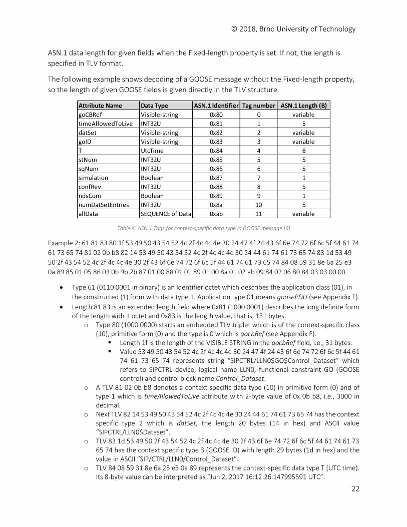
Standard 61850-8-1 [6] defines the Fixed-length property for a GOOSE messages. This property
means that the publisher will always use fixed offsets for each different field in the message. The
Fixed-length property configuration occurs for each GOOSE Control Block. Table 4 shows the
© 2018, Brno University of Technology
22
ASN.1 data length for given fields when the Fixed-length property is set. If not, the length is
specified in TLV format.
The following example shows decoding of a GOOSE message without the Fixed-length property,
so the length of given GOOSE fields is given directly in the TLV structure.
Table 4: ASN.1 Tags for context-specific data type in GOOSE message [6]
Example 2: 61 81 83 80 1f 53 49 50 43 54 52 4c 2f 4c 4c 4e 30 24 47 4f 24 43 6f 6e 74 72 6f 6c 5f 44 61 74
61 73 65 74 81 02 0b b8 82 14 53 49 50 43 54 52 4c 2f 4c 4c 4e 30 24 44 61 74 61 73 65 74 83 1d 53 49
50 2f 43 54 52 4c 2f 4c 4c 4e 30 2f 43 6f 6e 74 72 6f 6c 5f 44 61 74 61 73 65 74 84 08 59 31 8e 6a 25 e3
0a 89 85 01 05 86 03 0b 9b 2b 87 01 00 88 01 01 89 01 00 8a 01 02 ab 09 84 02 06 80 84 03 03 00 00
Type 61 (0110 0001 in binary) is an identifier octet which describes the application class (01), in
the constructed (1) form with data type 1. Application type 01 means goosePDU (see Appendix F).
Length 81 83 is an extended length field where 0x81 (1000 0001) describes the long definite form of the length with 1 octet and 0x83 is the length value, that is, 131 bytes.
o Type 80 (1000 0000) starts an embedded TLV triplet which is of the context-specific class (10), primitive form (0) and the type is 0 which is gocbRef (see Appendix F).
Length 1f is the length of the VISIBLE STRING in the gocbRef field, i.e., 31 bytes. Value 53 49 50 43 54 52 4c 2f 4c 4c 4e 30 24 47 4f 24 43 6f 6e 74 72 6f 6c 5f 44 61
74 61 73 65 74 represents string “SIPCTRL/LLN0$GO$Control_Dataset” which refers to SIPCTRL device, logical name LLN0, functional constraint GO (GOOSE control) and control block name Control_Dataset.
o A TLV 81 02 0b b8 denotes a context specific data type (10) in primitive form (0) and of type 1 which is timeAllowedToLive attribute with 2-byte value of 0x 0b b8, i.e., 3000 in decimal.
o Next TLV 82 14 53 49 50 43 54 52 4c 2f 4c 4c 4e 30 24 44 61 74 61 73 65 74 has the context specific type 2 which is datSet, the length 20 bytes (14 in hex) and ASCII value “SIPCTRL/LLN0$Dataset”.
o TLV 83 1d 53 49 50 2f 43 54 52 4c 2f 4c 4c 4e 30 2f 43 6f 6e 74 72 6f 6c 5f 44 61 74 61 73 65 74 has the context specific type 3 (GOOSE ID) with length 29 bytes (1d in hex) and the value in ASCII “SIP/CTRL/LLN0/Control_Dataset”.
o TLV 84 08 59 31 8e 6a 25 e3 0a 89 represents the context-specific data type T (UTC time). Its 8-byte value can be interpreted as “Jun 2, 2017 16:12:26.147995591 UTC”.
Attribute Name Data Type ASN.1 Identifier Tag number ASN.1 Length (B)
goCBRef Visible-string 0x80 0 variable
timeAllowedToLive INT32U 0x81 1 5
datSet Visible-string 0x82 2 variable
goID Visible-string 0x83 3 variable
T UtcTime 0x84 4 8
stNum INT32U 0x85 5 5
sqNum INT32U 0x86 6 5
simulation Boolean 0x87 7 1
confRev INT32U 0x88 8 5
ndsCom Boolean 0x89 9 1
numDatSetEntries INT32U 0x8a 10 5
allData SEQUENCE of Data 0xab 11 variable
© 2018, Brno University of Technology
23
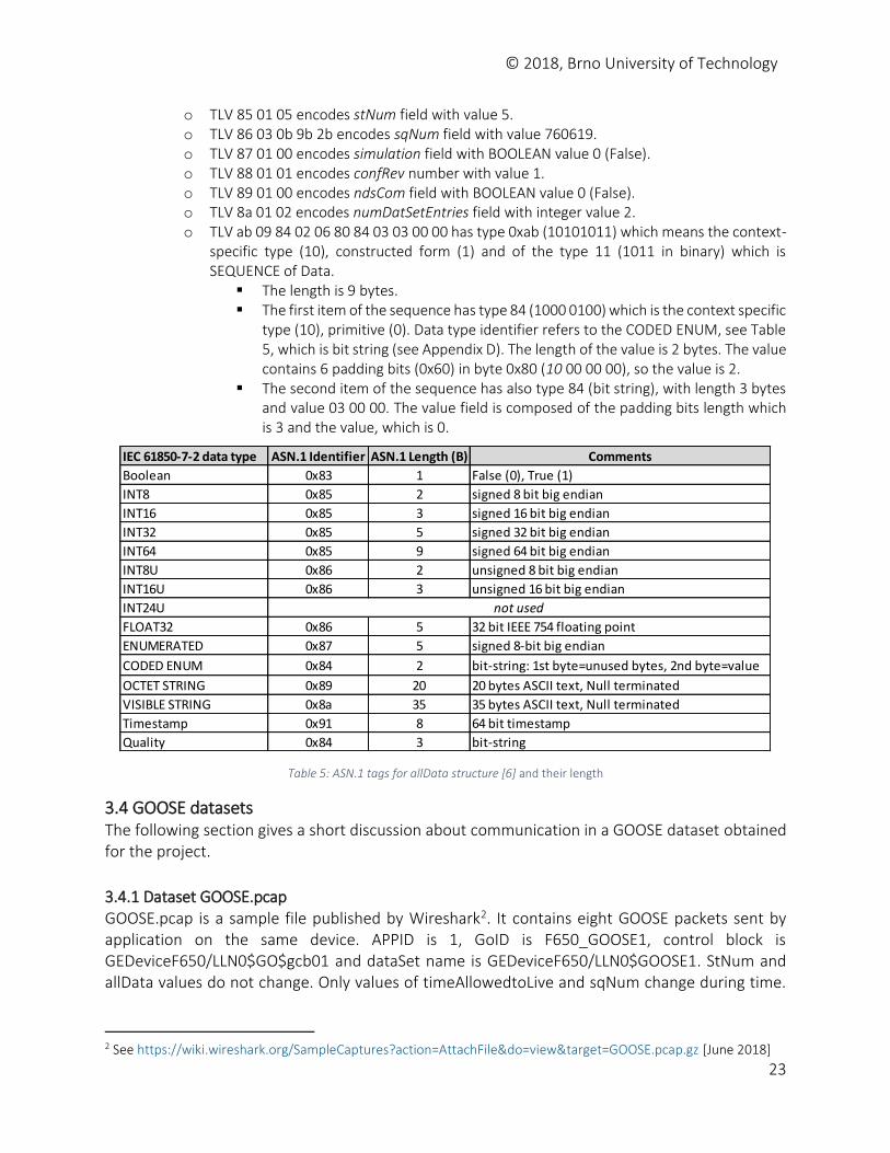
o TLV 85 01 05 encodes stNum field with value 5. o TLV 86 03 0b 9b 2b encodes sqNum field with value 760619. o TLV 87 01 00 encodes simulation field with BOOLEAN value 0 (False). o TLV 88 01 01 encodes confRev number with value 1. o TLV 89 01 00 encodes ndsCom field with BOOLEAN value 0 (False). o TLV 8a 01 02 encodes numDatSetEntries field with integer value 2. o TLV ab 09 84 02 06 80 84 03 03 00 00 has type 0xab (10101011) which means the context-
specific type (10), constructed form (1) and of the type 11 (1011 in binary) which is SEQUENCE of Data.
The length is 9 bytes. The first item of the sequence has type 84 (1000 0100) which is the context specific
type (10), primitive (0). Data type identifier refers to the CODED ENUM, see Table 5, which is bit string (see Appendix D). The length of the value is 2 bytes. The value contains 6 padding bits (0x60) in byte 0x80 (10 00 00 00), so the value is 2.
The second item of the sequence has also type 84 (bit string), with length 3 bytes and value 03 00 00. The value field is composed of the padding bits length which is 3 and the value, which is 0.
Table 5: ASN.1 tags for allData structure [6] and their length
3.4 GOOSE datasets The following section gives a short discussion about communication in a GOOSE dataset obtained for the project.
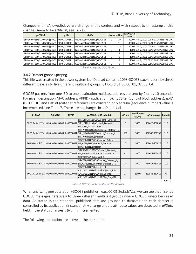
3.4.1 Dataset GOOSE.pcap GOOSE.pcap is a sample file published by Wireshark2. It contains eight GOOSE packets sent by application on the same device. APPID is 1, GoID is F650_GOOSE1, control block is GEDeviceF650/LLN0$GO$gcb01 and dataSet name is GEDeviceF650/LLN0$GOOSE1. StNum and allData values do not change. Only values of timeAllowedtoLive and sqNum change during time.
2 See https://wiki.wireshark.org/SampleCaptures?action=AttachFile&do=view&target=GOOSE.pcap.gz [June 2018]
IEC 61850-7-2 data type ASN.1 Identifier ASN.1 Length (B) Comments
Boolean 0x83 1 False (0), True (1)
INT8 0x85 2 signed 8 bit big endian
INT16 0x85 3 signed 16 bit big endian
INT32 0x85 5 signed 32 bit big endian
INT64 0x85 9 signed 64 bit big endian
INT8U 0x86 2 unsigned 8 bit big endian
INT16U 0x86 3 unsigned 16 bit big endian
INT24U
FLOAT32 0x86 5 32 bit IEEE 754 floating point
ENUMERATED 0x87 5 signed 8-bit big endian
CODED ENUM 0x84 2 bit-string: 1st byte=unused bytes, 2nd byte=value
OCTET STRING 0x89 20 20 bytes ASCII text, Null terminated
VISIBLE STRING 0x8a 35 35 bytes ASCII text, Null terminated
Timestamp 0x91 8 64 bit timestamp
Quality 0x84 3 bit-string
not used
© 2018, Brno University of Technology
24
Changes in timeAllowedtoLive are strange in this context and with respect to timestamp t, this changes seem to be artificial, see Table 6.
Table 6: Analyzing GOOSE data
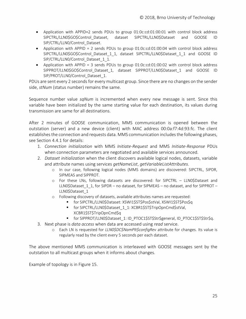
3.4.2 Dataset goose1.pcapng This file was created in the power system lab. Dataset contains 1093 GOOSE packets sent by three different devices to five different multicast groups: 01:0c:cd:01:00:00, 01, 02, 03, 04. GOOSE packets from one IED to one destination multicast address are sent by 2 or by 10 seconds. For given destination MAC address, APPID (application ID), goCBRef (control block address), goID (GOOSE ID) and DatSet (date set reference) are constant, only sqNum (sequence number) value is incremented, see Table 7. There are no changes in allData block.
Table 7: GOOSE packets values in the dataset
When analyzing one outstation (GOOSE publisher), e.g., 00:09:8e:fa:b7:1c, we can see that it sends GOOSE messages iteratively to three different multicast groups where GOOSE subscribers read data. As stated in the standard, published data are grouped to datasets and each dataset is controlled by its application (instance). Any change of data attribute values are detected in allData field. If the status changes, stNum is incremented. The following application are active at the outstation:
goCBRef goID datSet stNum sqNumtimeAllowed
toLivet
GEDeviceF650/LLN0$GO$gcb01 F650_GOOSE1 GEDeviceF650/LLN0$GOOSE1 1 10 40000 Jan 2, 2000 02:46:11.258165836 UTC
GEDeviceF650/LLN0$GO$gcb01 F650_GOOSE1 GEDeviceF650/LLN0$GOOSE1 1 11 40000 Jan 2, 2000 02:46:11.258165836 UTC
GEDeviceF650/LLN0$GO$gcb01 F650_GOOSE1 GEDeviceF650/LLN0$GOOSE1 1 12 40000 Jan 2, 2000 02:46:11.258165836 UTC
GEDeviceF650/LLN0$GO$gcb01 F650_GOOSE1 GEDeviceF650/LLN0$GOOSE1 1 1 1000 Jan 2, 2000 02:47:29.927595853 UTC
GEDeviceF650/LLN0$GO$gcb01 F650_GOOSE1 GEDeviceF650/LLN0$GOOSE1 1 2 1000 Jan 2, 2000 02:47:29.927595853 UTC
GEDeviceF650/LLN0$GO$gcb01 F650_GOOSE1 GEDeviceF650/LLN0$GOOSE1 1 3 1000 Jan 2, 2000 02:47:29.927595853 UTC
GEDeviceF650/LLN0$GO$gcb01 F650_GOOSE1 GEDeviceF650/LLN0$GOOSE1 1 4 2000 Jan 2, 2000 02:47:29.927595853 UTC
GEDeviceF650/LLN0$GO$gcb01 F650_GOOSE1 GEDeviceF650/LLN0$GOOSE1 1 5 40000 Jan 2, 2000 02:47:29.927595853 UTC
Src MAC Dst MAC APPID goCBRef - goID - datSet stNumtimeAllowed
toLivesqNum range Packets
SIP1CTRL/LLN0$GO$Control_Dataset
SIP1/CTRL/LLN0/Control_Dataset
SIP1CTRL/LLN0$Dataset
SIP1PROT/LLN0$GO$Control_Dataset_1
SIP1/PROT/LLN0/Control_Dataset_1
SIP1PROT/LLN0$Dataset_1
SIPCTRL/LLN0$GO$Control_Dataset
SIP/CTRL/LLN0/Control_Dataset
SIPCTRL/LLN0$Dataset
SIPPROT/LLN0$GO$Control_Dataset_1
SIP/PROT/LLN0/Control_Dataset_1
SIPPROT/LLN0$Dataset_1
SIPCTRL/LLN0$GO$Control_Dataset_1_1
SIP/CTRL/LLN0/Control_Dataset_1_1
SIPCTRL/LLN0$Dataset_1_1
AA1J1Q01A1LD0/LLN0$GO$LEDs_info
AA1J1Q01A1LD0/LLN0.LEDs_info
AA1J1Q01A1LD0/LLN0$LEDs_ON_OFF
1093
1100023
760617-760826
112568-112610
210
43
81
75
3000 760617-760826 210
3000
210
00:09:8e:fa:b7:1c
00:09:8e:fa:b7:1c
00:21:c1:25:08:a2
01:0c:cd:01:00:02 0x00000003
01:0c:cd:01:00:04 0x00000005
01:0c:cd:01:00:00 0x00000001
00:09:8e:fa:b7:1c 01:0c:cd:01:00:01 0x00000002 5 3000 760617-760826
210
00:09:8e:fa:b7:1a 01:0c:cd:01:00:03 0x00000004 186 3000 760548-760757 210
00:09:8e:fa:b7:1a 01:0c:cd:01:00:00 0x00000001 3 3000 760626-760835
© 2018, Brno University of Technology
25
Application with APPID=2 sends PDUs to group 01:0c:cd:01:00:01 with control block address SIPCTRL/LLN0$GO$Control_Dataset, dataset SIPCTRL/LLN0$Dataset and GOOSE ID SIP/CTRL/LLN0/Control_Dataset.
Application with APPID = 2 sends PDUs to group 01:0c:cd:01:00:04 with control block address SIPCTRL/LLN0$GO$Control_Dataset_1_1, dataset SIPCTRL/LLN0$Dataset_1_1 and GOOSE ID SIP/CTRL/LLN0/Control_Dataset_1_1.
Application with APPID = 3 sends PDUs to group 01:0c:cd:01:00:02 with control block address SIPPROT/LLN0$GO$Control_Dataset_1, dataset SIPPROT/LLN0$Dataset_1 and GOOSE ID SIP/PROT/LLN0/Control_Dataset_1.
PDUs are sent every 2 seconds for every multicast group. Since there are no changes on the sender side, stNum (status number) remains the same. Sequence number value sqNum is incremented when every new message is sent. Since this variable have been initialized by the same starting value for each destination, its values during transmission are same for all destinations. After 2 minutes of GOOSE communication, MMS communication is opened between the outstation (server) and a new device (client) with MAC address 00:0a:f7:4d:93:fc. The client establishes the connection and requests data. MMS communication includes the following phases, see Section 4.4.1 for details:
1. Connection initialization with MMS Initiate-Request and MMS Initiate-Response PDUs when connection parameters are negotiated and available services announced.
2. Dataset initialization when the client discovers available logical nodes, datasets, variable and attribute names using services getNameList, getVariableListAttributes.
o In our case, following logical nodes (MMS domains) are discovered: SIPCTRL, SIPDR, SIPMEAS and SIPPROT.
o For these LNs, following datasets are discovered: for SIPCTRL – LLN0$Dataset and LLN0$Dataset_1_1, for SIPDR – no dataset, for SIPMEAS – no dataset, and for SIPPROT – LLN0$Dataset_1
o Following discovery of datasets, available attributes names are requested: for SIPCTRL/LLN0$Dataset: XSWI1$ST$Pos$stVal, XSWI1$ST$Pos$q for SIPCTRL/LLN0$Dataset_1_1: XCBR1$ST$TripOpnCmd$stVal,
XCBR1$ST$TripOpnCmd$q for SIPPROT/LLN0$Dataset_1: ID_PTOC1$ST$Str$general, ID_PTOC1$ST$Str$q.
3. Next phase is data access when data are accessed using read service. o Each LN is requested for LLN0$DC$NamPlt$configRev attribute for changes. Its value is
regularly read by the client every 5 seconds per each dataset.
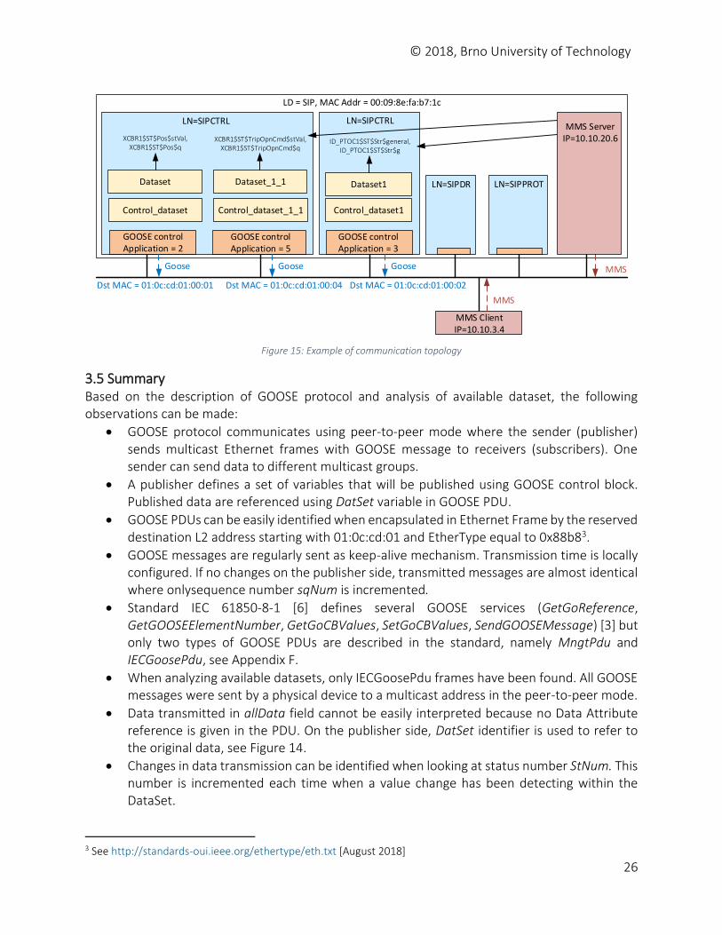
The above mentioned MMS communication is interleaved with GOOSE messages sent by the outstation to all multicast groups when it informs about changes. Example of topology is in Figure 15.
© 2018, Brno University of Technology
26
Dataset
Control_dataset
Dataset1
Control_dataset1
LN=SIPCTRL LN=SIPCTRL
Dataset_1_1
Control_dataset_1_1
Goose Goose Goose
Dst MAC = 01:0c:cd:01:00:01 Dst MAC = 01:0c:cd:01:00:04 Dst MAC = 01:0c:cd:01:00:02
LN=SIPDR LN=SIPPROT
LD = SIP, MAC Addr = 00:09:8e:fa:b7:1c
XCBR1$ST$Pos$stVal,XCBR1$ST$Pos$q
XCBR1$ST$TripOpnCmd$stVal,XCBR1$ST$TripOpnCmd$q
ID_PTOC1$ST$Str$general, ID_PTOC1$ST$Str$g
MMS ClientIP=10.10.3.4
MMS
MMS
GOOSE controlApplication = 2
GOOSE controlApplication = 5
GOOSE controlApplication = 3
MMS ServerIP=10.10.20.6
Figure 15: Example of communication topology
3.5 Summary Based on the description of GOOSE protocol and analysis of available dataset, the following observations can be made:
GOOSE protocol communicates using peer-to-peer mode where the sender (publisher) sends multicast Ethernet frames with GOOSE message to receivers (subscribers). One sender can send data to different multicast groups.
A publisher defines a set of variables that will be published using GOOSE control block. Published data are referenced using DatSet variable in GOOSE PDU.
GOOSE PDUs can be easily identified when encapsulated in Ethernet Frame by the reserved destination L2 address starting with 01:0c:cd:01 and EtherType equal to 0x88b83.
GOOSE messages are regularly sent as keep-alive mechanism. Transmission time is locally configured. If no changes on the publisher side, transmitted messages are almost identical where onlysequence number sqNum is incremented.
Standard IEC 61850-8-1 [6] defines several GOOSE services (GetGoReference, GetGOOSEElementNumber, GetGoCBValues, SetGoCBValues, SendGOOSEMessage) [3] but only two types of GOOSE PDUs are described in the standard, namely MngtPdu and IECGoosePdu, see Appendix F.
When analyzing available datasets, only IECGoosePdu frames have been found. All GOOSE messages were sent by a physical device to a multicast address in the peer-to-peer mode.
Data transmitted in allData field cannot be easily interpreted because no Data Attribute reference is given in the PDU. On the publisher side, DatSet identifier is used to refer to the original data, see Figure 14.
Changes in data transmission can be identified when looking at status number StNum. This number is incremented each time when a value change has been detecting within the DataSet.
3 See http://standards-oui.ieee.org/ethertype/eth.txt [August 2018]
© 2018, Brno University of Technology
27
4 MMS Protocol MMS (Manufacturing Message Specification) is a messaging system for modeling real devices and functions and for exchanging information about the real device, and exchanging process data – under real-time conditions – and supervisory control information between networked devices and/or computer applications. MMS is defined by standards ISO/IEC 9506-1 (Services) and ISO/IEC 9506-2 (Protocol).
The service specification contains definition of the Virtual Manufacturing Device (VMD), services (and messages) exchanged between nodes on a network, and the attributes and parameters associated with the VMD and services.
The protocol specification defines the rules of communication, i.e., the sequencing of messages across the network, the format and encoding of the messages, and the interaction of the MMS layer with the other layers of the communications network.
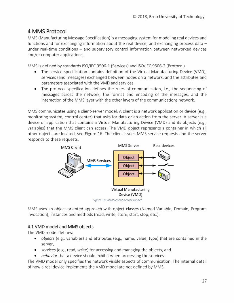
MMS communicates using a client-server model. A client is a network application or device (e.g., monitoring system, control center) that asks for data or an action from the server. A server is a device or application that contains a Virtual Manufacturing Device (VMD) and its objects (e.g., variables) that the MMS client can access. The VMD object represents a container in which all other objects are located, see Figure 16. The client issues MMS service requests and the server responds to these requests.
Object
MMS Client MMS Server
Object
Object
Virtual Manufacturing Device (VMD)
MMS Services
Real devices
Figure 16: MMS client-server model
MMS uses an object-oriented approach with object classes (Named Variable, Domain, Program invocation), instances and methods (read, write, store, start, stop, etc.).
4.1 VMD model and MMS objects The VMD model defines:
objects (e.g., variables) and attributes (e.g., name, value, type) that are contained in the server,
services (e.g., read, write) for accessing and managing the objects, and
behavior that a device should exhibit when processing the services. The VMD model only specifies the network visible aspects of communication. The internal detail of how a real device implements the VMD model are not defined by MMS.
© 2018, Brno University of Technology
28
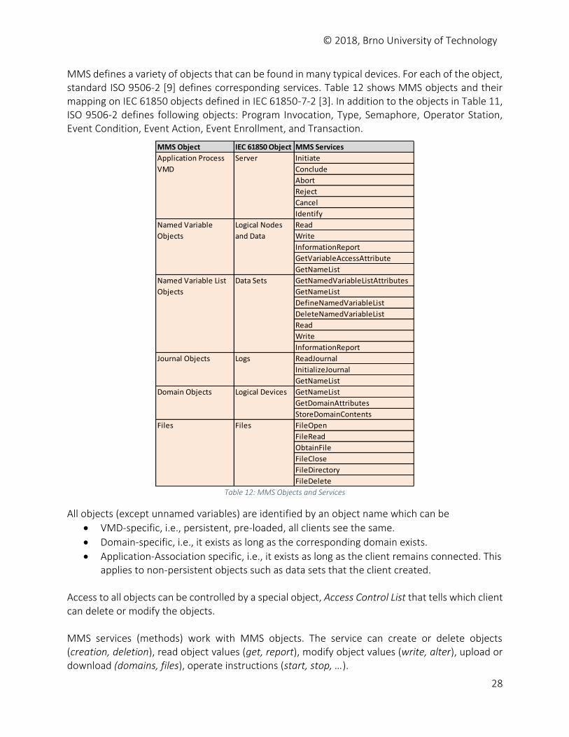
MMS defines a variety of objects that can be found in many typical devices. For each of the object, standard ISO 9506-2 [9] defines corresponding services. Table 12 shows MMS objects and their mapping on IEC 61850 objects defined in IEC 61850-7-2 [3]. In addition to the objects in Table 11, ISO 9506-2 defines following objects: Program Invocation, Type, Semaphore, Operator Station, Event Condition, Event Action, Event Enrollment, and Transaction.
Table 12: MMS Objects and Services
All objects (except unnamed variables) are identified by an object name which can be
VMD-specific, i.e., persistent, pre-loaded, all clients see the same.
Domain-specific, i.e., it exists as long as the corresponding domain exists.
Application-Association specific, i.e., it exists as long as the client remains connected. This applies to non-persistent objects such as data sets that the client created.
Access to all objects can be controlled by a special object, Access Control List that tells which client can delete or modify the objects. MMS services (methods) work with MMS objects. The service can create or delete objects (creation, deletion), read object values (get, report), modify object values (write, alter), upload or download (domains, files), operate instructions (start, stop, …).
MMS Object IEC 61850 Object MMS Services
Initiate
Conclude
Abort
Reject
Cancel
Identify
Read
Write
InformationReport
GetVariableAccessAttribute
GetNameList
GetNamedVariableListAttributes
GetNameList
DefineNamedVariableList
DeleteNamedVariableList
Read
Write
InformationReport
ReadJournal
InitializeJournal
GetNameList
GetNameList
GetDomainAttributes
StoreDomainContents
FileOpen
FileRead
ObtainFile
FileClose
FileDirectory
FileDelete
Journal Objects Logs
Domain Objects Logical Devices
Files Files
Application Process
VMD
Server
Named Variable
Objects
Logical Nodes
and Data
Named Variable List
Objects
Data Sets
© 2018, Brno University of Technology
29
MMS also provides service such as Status, Unsolicited Status, and Identify for obtaining information about the VMD. The service GetNameList provides managing and obtaining information about objects defined in the VMD by retrieving the name and type of all named objects in the VMD, see Appendix E. MMS works with named and unnamed variables.
Unnamed variables (vadr) are identified by a fixed physical address in the VMD, e.g., numericAddress (0xAF043BC0), symbolicAddress (MW%1004), or unconstrainedAddress (0x76AA).
Name variables (vnam) are identified by an object name. When accessing data, MMS provides serviced to build a Data Set which is a group of variables that is to be transmitted as a whole. This is generally done for each client specifically (application- association specific type). The client defines a list and populates it with the names of the variables and the transmission mode. MMS domain is a named MMS object that is a representation of some resource within the real device. In many typical applications, domains are used to represent area of memory in a device. Objects (variables, events, program invocations, …) may be tied to a domain. Each domain is controlled by a state machine in MMS.
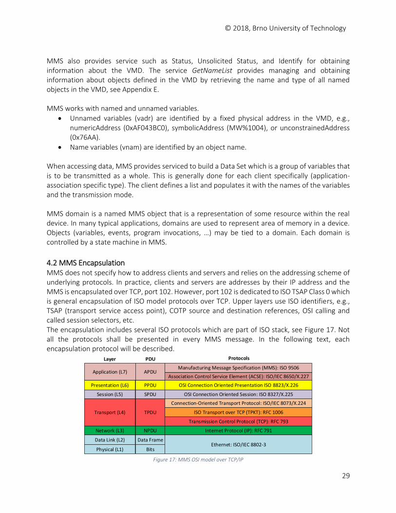
4.2 MMS Encapsulation MMS does not specify how to address clients and servers and relies on the addressing scheme of underlying protocols. In practice, clients and servers are addresses by their IP address and the MMS is encapsulated over TCP, port 102. However, port 102 is dedicated to ISO TSAP Class 0 which is general encapsulation of ISO model protocols over TCP. Upper layers use ISO identifiers, e.g., TSAP (transport service access point), COTP source and destination references, OSI calling and called session selectors, etc. The encapsulation includes several ISO protocols which are part of ISO stack, see Figure 17. Not all the protocols shall be presented in every MMS message. In the following text, each encapsulation protocol will be described.
Application (L7)
Presentation (L6)
Session (L5)
Transport (L4)
Network (L3)
Data Link (L2)
Association Control Service Element (ACSE): ISO/IEC 8650/X.227
OSI Connection Oriented Presentation ISO 8823/X.226
OSI Connection Oriented Session: ISO 8327/X.225
Transmission Control Protocol (TCP): RFC 793
Internet Protocol (IP): RFC 791
Ethernet: ISO/IEC 8802-3
ISO Transport over TCP (TPKT): RFC 1006
Connection-Oriented Transport Protocol: ISO/IEC 8073/X.224
Manufacturing Message Specification (MMS): ISO 9506
Physical (L1)
APDU
PPDU
SPDU
TPDU
NPDU
Data Frame
Bits
Layer PDU Protocols
Figure 17: MMS OSI model over TCP/IP
© 2018, Brno University of Technology
30
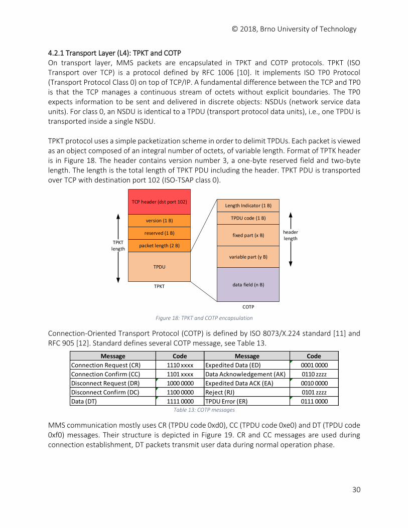
4.2.1 Transport Layer (L4): TPKT and COTP On transport layer, MMS packets are encapsulated in TPKT and COTP protocols. TPKT (ISO Transport over TCP) is a protocol defined by RFC 1006 [10]. It implements ISO TP0 Protocol (Transport Protocol Class 0) on top of TCP/IP. A fundamental difference between the TCP and TP0 is that the TCP manages a continuous stream of octets without explicit boundaries. The TP0 expects information to be sent and delivered in discrete objects: NSDUs (network service data units). For class 0, an NSDU is identical to a TPDU (transport protocol data units), i.e., one TPDU is transported inside a single NSDU. TPKT protocol uses a simple packetization scheme in order to delimit TPDUs. Each packet is viewed as an object composed of an integral number of octets, of variable length. Format of TPTK header is in Figure 18. The header contains version number 3, a one-byte reserved field and two-byte length. The length is the total length of TPKT PDU including the header. TPKT PDU is transported over TCP with destination port 102 (ISO-TSAP class 0).
TCP header (dst port 102)
version (1 B)
packet length (2 B)
reserved (1 B)
TPDU
Length Indicator (1 B)
TPDU code (1 B)
variable part (y B)
data field (n B)
fixed part (x B)
COTP
TPKT
TPKTlength
headerlength
Figure 18: TPKT and COTP encapsulation
Connection-Oriented Transport Protocol (COTP) is defined by ISO 8073/X.224 standard [11] and RFC 905 [12]. Standard defines several COTP message, see Table 13.
Table 13: COTP messages
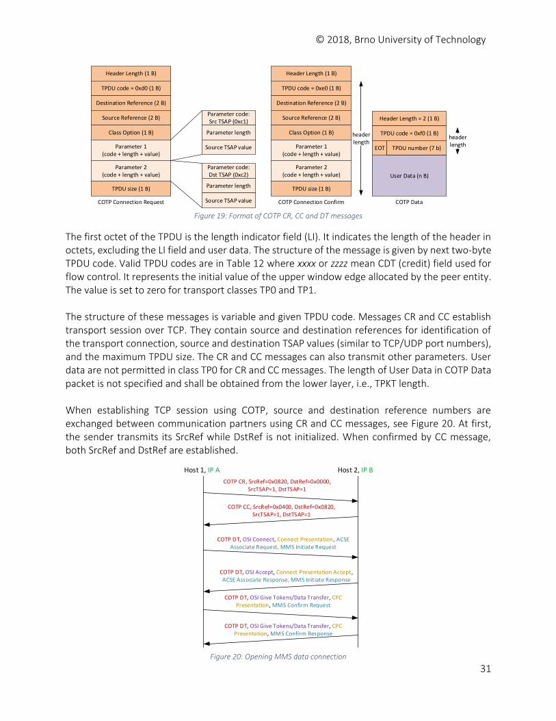
MMS communication mostly uses CR (TPDU code 0xd0), CC (TPDU code 0xe0) and DT (TPDU code 0xf0) messages. Their structure is depicted in Figure 19. CR and CC messages are used during connection establishment, DT packets transmit user data during normal operation phase.
Message Code Message Code
Connection Request (CR) 1110 xxxx Expedited Data (ED) 0001 0000
Connection Confirm (CC) 1101 xxxx Data Acknowledgement (AK) 0110 zzzz
Disconnect Request (DR) 1000 0000 Expedited Data ACK (EA) 0010 0000
Disconnect Confirm (DC) 1100 0000 Reject (RJ) 0101 zzzz
Data (DT) 1111 0000 TPDU Error (ER) 0111 0000
© 2018, Brno University of Technology
31
Header Length (1 B)
TPDU code = 0xd0 (1 B)
Destination Reference (2 B)
COTP Connection Request
Source Reference (2 B)
Class Option (1 B)
Parameter 1 (code + length + value)
TPDU size (1 B)
Parameter 2 (code + length + value)
Parameter code: Src TSAP (0xc1)
Parameter length
Source TSAP value
Parameter code: Dst TSAP (0xc2)
Parameter length
Source TSAP value
Header Length (1 B)
TPDU code = 0xe0 (1 B)
Destination Reference (2 B)
COTP Connection Confirm
Source Reference (2 B)
Class Option (1 B)
Parameter 1 (code + length + value)
TPDU size (1 B)
Parameter 2 (code + length + value)
Header Length = 2 (1 B)
TPDU code = 0xf0 (1 B)
TPDU number (7 b)
COTP Data
User Data (n B)
headerlength
headerlength
EOT
Figure 19: Format of COTP CR, CC and DT messages
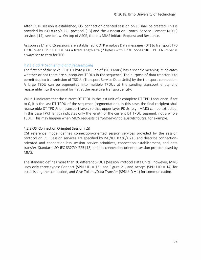
The first octet of the TPDU is the length indicator field (LI). It indicates the length of the header in octets, excluding the LI field and user data. The structure of the message is given by next two-byte TPDU code. Valid TPDU codes are in Table 12 where xxxx or zzzz mean CDT (credit) field used for flow control. It represents the initial value of the upper window edge allocated by the peer entity. The value is set to zero for transport classes TP0 and TP1. The structure of these messages is variable and given TPDU code. Messages CR and CC establish transport session over TCP. They contain source and destination references for identification of the transport connection, source and destination TSAP values (similar to TCP/UDP port numbers), and the maximum TPDU size. The CR and CC messages can also transmit other parameters. User data are not permitted in class TP0 for CR and CC messages. The length of User Data in COTP Data packet is not specified and shall be obtained from the lower layer, i.e., TPKT length. When establishing TCP session using COTP, source and destination reference numbers are exchanged between communication partners using CR and CC messages, see Figure 20. At first, the sender transmits its SrcRef while DstRef is not initialized. When confirmed by CC message, both SrcRef and DstRef are established.
Host 1, IP A Host 2, IP B
COTP CR, SrcRef=0x0820, DstRef=0x0000,SrcTSAP=1, DstTSAP=1
COTP CC, SrcRef=0x0400, DstRef=0x0820,SrcTSAP=1, DstTSAP=1
COTP DT, OSI Connect, Connect Presentation, ACSE Associate Request, MMS Initiate Request
COTP DT, OSI Accept, Connect Presentation Accept, ACSE Associate Response, MMS Initiate Response
COTP DT, OSI Give Tokens/Data Transfer, CPC Presentation, MMS Confirm Request
COTP DT, OSI Give Tokens/Data Transfer, CPC Presentation, MMS Confirm Response
Figure 20: Opening MMS data connection
© 2018, Brno University of Technology
32
After COTP session is established, OSI connection oriented session on L5 shall be created. This is provided by ISO 8327/X.225 protocol [13] and the Association Control Service Element (ASCE) services [14], see below. On top of ASCE, there is MMS Initiate Request and Response. As soon as L4 and L5 sessions are established, COTP employs Data messages (DT) to transport TP0 TPDU over TCP. COTP DT has a fixed length size (2 bytes) with TPDU code 0xf0. TPDU Number is always set to zero for TP0.
4.2.1.1 COTP Segmenting and Reassembling The first bit of the next COTP DT byte (EOT, End of TSDU Mark) has a specific meaning: it indicates whether or not there are subsequent TPDUs in the sequence. The purpose of data transfer is to permit duplex transmission of TSDUs (Transport Service Data Units) by the transport connection. A large TSDU can be segmented into multiple TPDUs at the sending transport entity and reassemble into the original format at the receiving transport entity. Value 1 indicates that the current DT TPDU is the last unit of a complete DT TPDU sequence. If set to 0, it is the last DT TPDU of the sequence (segmentation). In this case, the final recipient shall reassemble DT TPDUs on transport layer, so that upper layer PDUs (e.g., MMS) can be extracted. In this case TPKT length indicates only the length of the current DT TPDU segment, not a whole TSDU. This may happen when MMS requests getNamedVariableListAttributes, for example.
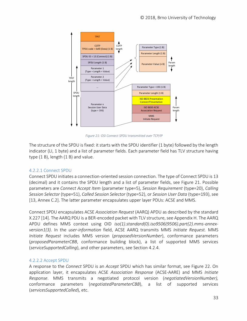
4.2.2 OSI Connection Oriented Session (L5) OSI reference model defines connection-oriented session services provided by the session protocol on L5. Session services are specified by ISO/IEC 8326/X.215 and describe connection-oriented and connection-less session service primitives, connection establishment, and data transfer. Standard ISO-IEC 8327/X.225 [13] defines connection-oriented session protocol used by MMS. The standard defines more than 30 different SPDUs (Session Protocol Data Units), however, MMS uses only three types: Connect (SPDU ID = 13), see Figure 21, and Accept (SPDU ID = 14) for establishing the connection, and Give Tokens/Data Transfer (SPDU ID = 1) for communication.
© 2018, Brno University of Technology
33
COTPTPDU code = 0xf0 (Data) (1 B)
SPDU ID = 13 (Connect) (1 B)
SPDU Length (1 B)
Parameter 1(Type + Length + Value)
ISO 8823 PresentationConnect Presentation
ISO 8650 ACSE Association Request
MMS Initiate Request
Parameter 2(Type + Length + Value)
Parameter nSession User Data
(type = 193)
...
Parameter Type (1 B)
Parameter Length (1 B)
Parameter Value (n B)
Parameter Type = 193 (1 B)
Parameter Length (1 B)
TPKTlength
SPDUlength
Paramlength
Paramlength
COTPlength
TPKT
Figure 21: OSI Connect SPDU transmitted over TCP/IP
The structure of the SPDU is fixed: it starts with the SPDU identifier (1 byte) followed by the length indicator (LI, 1 byte) and a list of parameter fields. Each parameter field has TLV structure having type (1 B), length (1 B) and value.
4.2.2.1 Connect SPDU Connect SPDU initiates a connection-oriented session connection. The type of Connect SPDU is 13 (decimal) and it contains the SPDU length and a list of parameter fields, see Figure 21. Possible parameters are Connect Accept Item (parameter type=5), Session Requirement (type=20), Calling Session Selector (type=51), Called Session Selector (type=52), or Session User Data (type=193), see [13, Annex C.2]. The latter parameter encapsulates upper layer PDUs: ACSE and MMS. Connect SPDU encapsulates ACSE Association Request (AARQ) APDU as described by the standard X.227 [14]. The AARQ PDU is a BER-encoded packet with TLV structure, see Appendix H. The AARQ APDU defines MMS context using OID iso(1).standard(0).iso9506(9506).part(2).mms-annex-version1(3). In the user-information field, ACSE AARQ transmits MMS Initiate Request. MMS Initiate Request includes MMS version (proposedVersionNumber), conformance parameters (proposedParameterCBB, conformance building block), a list of supported MMS services (serviceSupportedCalling), and other parameters, see Section 4.2.4.
4.2.2.2 Accept SPDU A response to the Connect SPDU is an Accept SPDU which has similar format, see Figure 22. On application layer, it encapsulates ACSE Association Response (ACSE-AARE) and MMS Initiate Response. MMS transmits a negotiated protocol version (negotiatedVersionNumber), conformance parameters (negotiatedParameterCBB), a list of supported services (servicesSupportedCalled), etc.
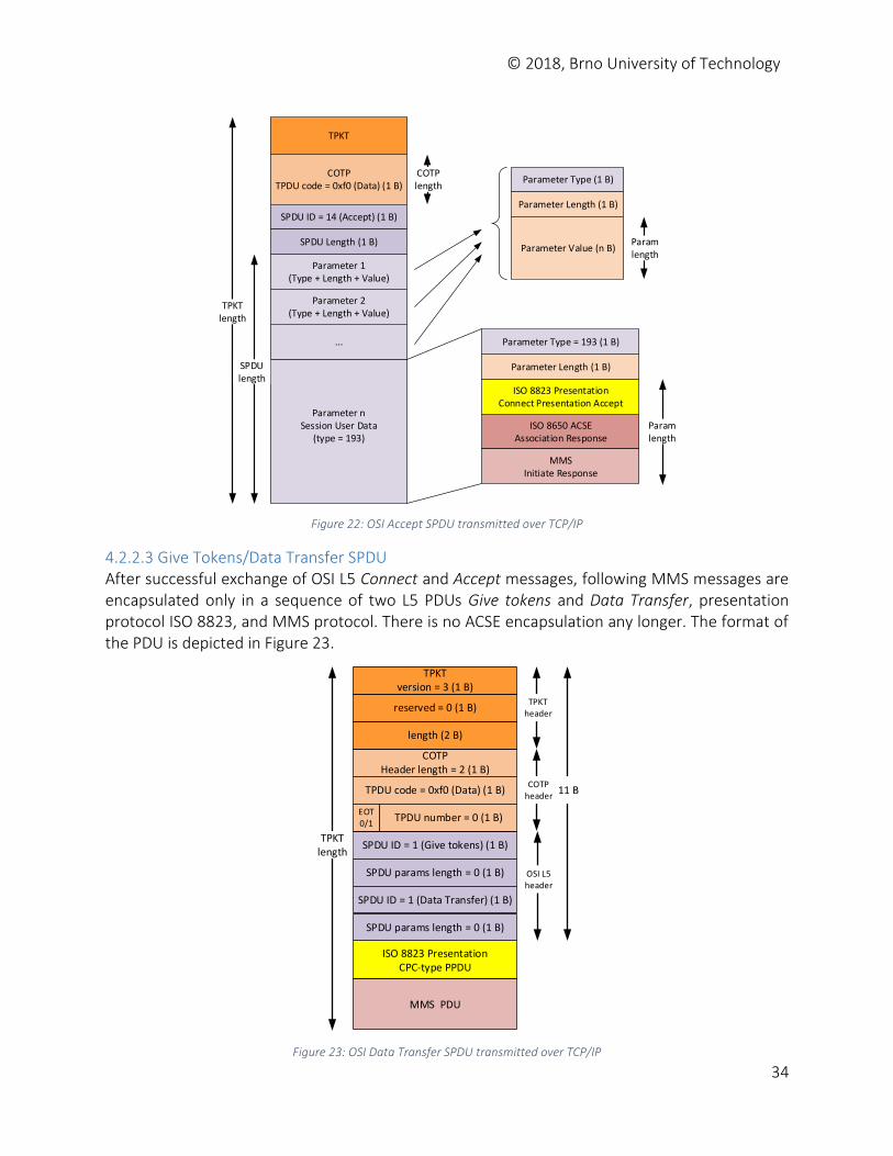
© 2018, Brno University of Technology
34
COTPTPDU code = 0xf0 (Data) (1 B)
SPDU ID = 14 (Accept) (1 B)
SPDU Length (1 B)
Parameter 1(Type + Length + Value)
ISO 8823 PresentationConnect Presentation Accept
ISO 8650 ACSE Association Response
MMS Initiate Response
Parameter 2(Type + Length + Value)
Parameter nSession User Data
(type = 193)
...
Parameter Type (1 B)
Parameter Length (1 B)
Parameter Value (n B)
Parameter Type = 193 (1 B)
Parameter Length (1 B)
TPKTlength
SPDUlength
Paramlength
Paramlength
COTPlength
TPKT
Figure 22: OSI Accept SPDU transmitted over TCP/IP
4.2.2.3 Give Tokens/Data Transfer SPDU After successful exchange of OSI L5 Connect and Accept messages, following MMS messages are encapsulated only in a sequence of two L5 PDUs Give tokens and Data Transfer, presentation protocol ISO 8823, and MMS protocol. There is no ACSE encapsulation any longer. The format of the PDU is depicted in Figure 23.
COTPHeader length = 2 (1 B)
SPDU ID = 1 (Give tokens) (1 B)
SPDU params length = 0 (1 B)
ISO 8823 PresentationCPC-type PPDU
MMS PDU
TPKTlength
TPKTheader
SPDU ID = 1 (Data Transfer) (1 B)
SPDU params length = 0 (1 B)
TPDU code = 0xf0 (Data) (1 B)
EOT0/1
TPDU number = 0 (1 B)
length (2 B)
reserved = 0 (1 B)
TPKTversion = 3 (1 B)
OSI L5header
11 BCOTP
header
Figure 23: OSI Data Transfer SPDU transmitted over TCP/IP
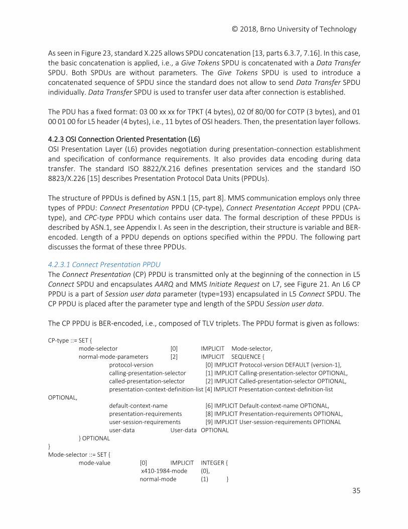
© 2018, Brno University of Technology
35
As seen in Figure 23, standard X.225 allows SPDU concatenation [13, parts 6.3.7, 7.16]. In this case, the basic concatenation is applied, i.e., a Give Tokens SPDU is concatenated with a Data Transfer SPDU. Both SPDUs are without parameters. The Give Tokens SPDU is used to introduce a concatenated sequence of SPDU since the standard does not allow to send Data Transfer SPDU individually. Data Transfer SPDU is used to transfer user data after connection is established. The PDU has a fixed format: 03 00 xx xx for TPKT (4 bytes), 02 0f 80/00 for COTP (3 bytes), and 01 00 01 00 for L5 header (4 bytes), i.e., 11 bytes of OSI headers. Then, the presentation layer follows.
4.2.3 OSI Connection Oriented Presentation (L6) OSI Presentation Layer (L6) provides negotiation during presentation-connection establishment and specification of conformance requirements. It also provides data encoding during data transfer. The standard ISO 8822/X.216 defines presentation services and the standard ISO 8823/X.226 [15] describes Presentation Protocol Data Units (PPDUs). The structure of PPDUs is defined by ASN.1 [15, part 8]. MMS communication employs only three types of PPDU: Connect Presentation PPDU (CP-type), Connect Presentation Accept PPDU (CPA-type), and CPC-type PPDU which contains user data. The formal description of these PPDUs is described by ASN.1, see Appendix I. As seen in the description, their structure is variable and BER-encoded. Length of a PPDU depends on options specified within the PPDU. The following part discusses the format of these three PPDUs.
4.2.3.1 Connect Presentation PPDU The Connect Presentation (CP) PPDU is transmitted only at the beginning of the connection in L5 Connect SPDU and encapsulates AARQ and MMS Initiate Request on L7, see Figure 21. An L6 CP PPDU is a part of Session user data parameter (type=193) encapsulated in L5 Connect SPDU. The CP PPDU is placed after the parameter type and length of the SPDU Session user data. The CP PPDU is BER-encoded, i.e., composed of TLV triplets. The PPDU format is given as follows: CP-type ::= SET { mode-selector [0] IMPLICIT Mode-selector, normal-mode-parameters [2] IMPLICIT SEQUENCE { protocol-version [0] IMPLICIT Protocol-version DEFAULT {version-1}, calling-presentation-selector [1] IMPLICIT Calling-presentation-selector OPTIONAL, called-presentation-selector [2] IMPLICIT Called-presentation-selector OPTIONAL, presentation-context-definition-list [4] IMPLICIT Presentation-context-definition-list OPTIONAL, default-context-name [6] IMPLICIT Default-context-name OPTIONAL, presentation-requirements [8] IMPLICIT Presentation-requirements OPTIONAL, user-session-requirements [9] IMPLICIT User-session-requirements OPTIONAL user-data User-data OPTIONAL } OPTIONAL } Mode-selector ::= SET { mode-value [0] IMPLICIT INTEGER { x410-1984-mode (0), normal-mode (1) }
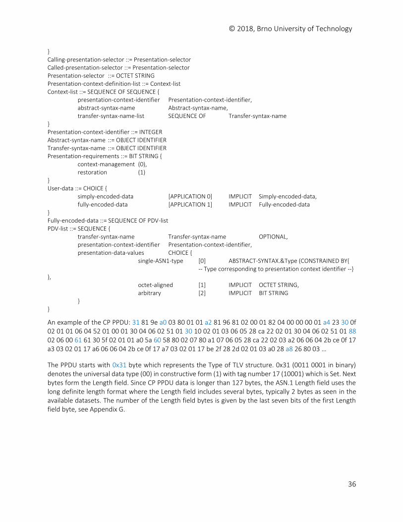
© 2018, Brno University of Technology
36
} Calling-presentation-selector ::= Presentation-selector Called-presentation-selector ::= Presentation-selector Presentation-selector ::= OCTET STRING Presentation-context-definition-list ::= Context-list Context-list ::= SEQUENCE OF SEQUENCE { presentation-context-identifier Presentation-context-identifier, abstract-syntax-name Abstract-syntax-name, transfer-syntax-name-list SEQUENCE OF Transfer-syntax-name } Presentation-context-identifier ::= INTEGER Abstract-syntax-name ::= OBJECT IDENTIFIER Transfer-syntax-name ::= OBJECT IDENTIFIER Presentation-requirements ::= BIT STRING { context-management (0), restoration (1) } User-data ::= CHOICE { simply-encoded-data [APPLICATION 0] IMPLICIT Simply-encoded-data, fully-encoded-data [APPLICATION 1] IMPLICIT Fully-encoded-data } Fully-encoded-data ::= SEQUENCE OF PDV-list PDV-list ::= SEQUENCE { transfer-syntax-name Transfer-syntax-name OPTIONAL, presentation-context-identifier Presentation-context-identifier, presentation-data-values CHOICE { single-ASN1-type [0] ABSTRACT-SYNTAX.&Type (CONSTRAINED BY{ -- Type corresponding to presentation context identifier --} ), octet-aligned [1] IMPLICIT OCTET STRING, arbitrary [2] IMPLICIT BIT STRING } }
An example of the CP PPDU: 31 81 9e a0 03 80 01 01 a2 81 96 81 02 00 01 82 04 00 00 00 01 a4 23 30 0f 02 01 01 06 04 52 01 00 01 30 04 06 02 51 01 30 10 02 01 03 06 05 28 ca 22 02 01 30 04 06 02 51 01 88 02 06 00 61 61 30 5f 02 01 01 a0 5a 60 58 80 02 07 80 a1 07 06 05 28 ca 22 02 03 a2 06 06 04 2b ce 0f 17 a3 03 02 01 17 a6 06 06 04 2b ce 0f 17 a7 03 02 01 17 be 2f 28 2d 02 01 03 a0 28 a8 26 80 03 …
The PPDU starts with 0x31 byte which represents the Type of TLV structure. 0x31 (0011 0001 in binary) denotes the universal data type (00) in constructive form (1) with tag number 17 (10001) which is Set. Next bytes form the Length field. Since CP PPDU data is longer than 127 bytes, the ASN.1 Length field uses the long definite length format where the Length field includes several bytes, typically 2 bytes as seen in the available datasets. The number of the Length field bytes is given by the last seven bits of the first Length field byte, see Appendix G.
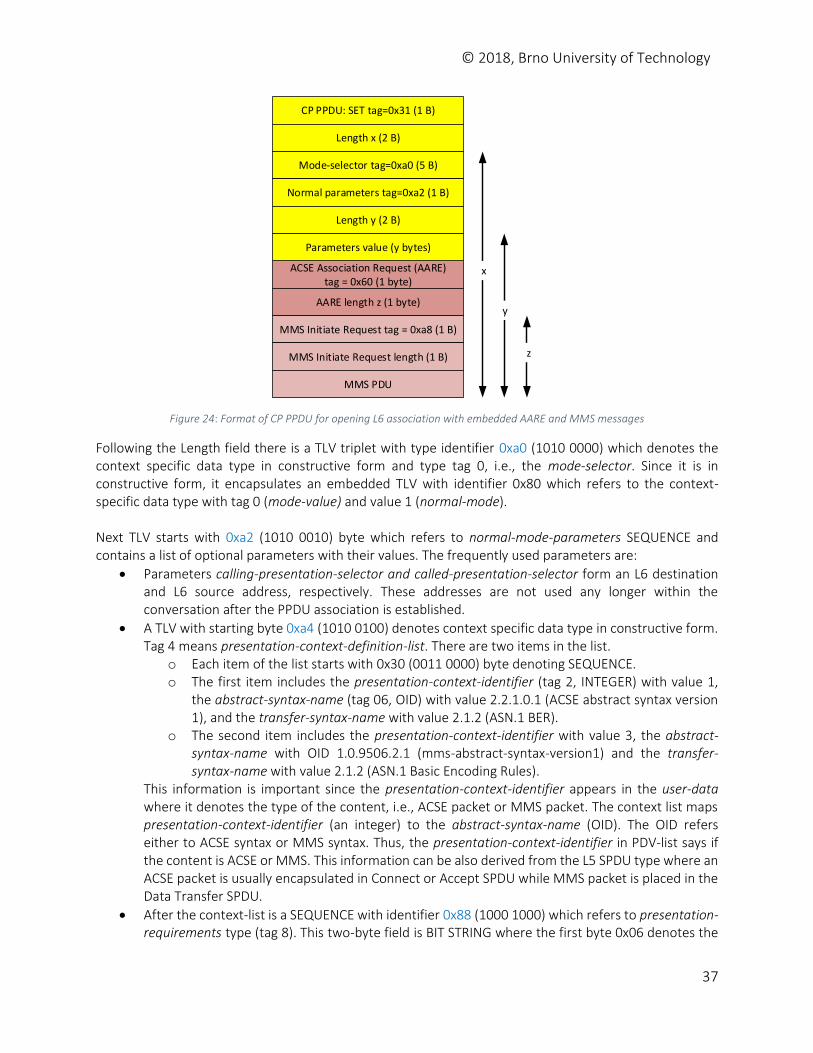
© 2018, Brno University of Technology
37
CP PPDU: SET tag=0x31 (1 B)
Length x (2 B)
Mode-selector tag=0xa0 (5 B)
Normal parameters tag=0xa2 (1 B)
Length y (2 B)
ACSE Association Request (AARE)tag = 0x60 (1 byte)
Parameters value (y bytes)
AARE length z (1 byte)
MMS Initiate Request tag = 0xa8 (1 B)
MMS Initiate Request length (1 B)
MMS PDU
x
y
z
Figure 24: Format of CP PPDU for opening L6 association with embedded AARE and MMS messages
Following the Length field there is a TLV triplet with type identifier 0xa0 (1010 0000) which denotes the context specific data type in constructive form and type tag 0, i.e., the mode-selector. Since it is in constructive form, it encapsulates an embedded TLV with identifier 0x80 which refers to the context-specific data type with tag 0 (mode-value) and value 1 (normal-mode). Next TLV starts with 0xa2 (1010 0010) byte which refers to normal-mode-parameters SEQUENCE and contains a list of optional parameters with their values. The frequently used parameters are:
Parameters calling-presentation-selector and called-presentation-selector form an L6 destination and L6 source address, respectively. These addresses are not used any longer within the conversation after the PPDU association is established.
A TLV with starting byte 0xa4 (1010 0100) denotes context specific data type in constructive form. Tag 4 means presentation-context-definition-list. There are two items in the list.
o Each item of the list starts with 0x30 (0011 0000) byte denoting SEQUENCE. o The first item includes the presentation-context-identifier (tag 2, INTEGER) with value 1,
the abstract-syntax-name (tag 06, OID) with value 2.2.1.0.1 (ACSE abstract syntax version 1), and the transfer-syntax-name with value 2.1.2 (ASN.1 BER).
o The second item includes the presentation-context-identifier with value 3, the abstract-syntax-name with OID 1.0.9506.2.1 (mms-abstract-syntax-version1) and the transfer-syntax-name with value 2.1.2 (ASN.1 Basic Encoding Rules).
This information is important since the presentation-context-identifier appears in the user-data where it denotes the type of the content, i.e., ACSE packet or MMS packet. The context list maps presentation-context-identifier (an integer) to the abstract-syntax-name (OID). The OID refers either to ACSE syntax or MMS syntax. Thus, the presentation-context-identifier in PDV-list says if the content is ACSE or MMS. This information can be also derived from the L5 SPDU type where an ACSE packet is usually encapsulated in Connect or Accept SPDU while MMS packet is placed in the Data Transfer SPDU.
After the context-list is a SEQUENCE with identifier 0x88 (1000 1000) which refers to presentation-requirements type (tag 8). This two-byte field is BIT STRING where the first byte 0x06 denotes the
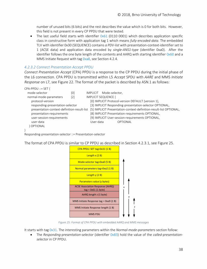
© 2018, Brno University of Technology
38
number of unused bits (6 bits) and the rest describes the value which is 0 for both bits. However, this field is not present in every CP PPDU that were tested.
The last useful field starts with identifier 0x61 (0110 0001) which describes application specific class in constructive form with application tag 1 which means fully-encoded-data. The embedded TLV with identifier 0x30 (SEQUENCE) contains a PDV-list with presentation-context-identifier set to 1 (ACSE data) and application data encoded by single-ANS1-type (identifier 0xa0). After the identifier follows the one byte length of the contents and AARQ with starting identifier 0x60 and a MMS Initiate Request with tag 0xa8, see Section 4.2.4.
4.2.3.2 Connect Presentation Accept PPDU Connect Presentation Accept (CPA) PPDU is a response to the CP PPDU during the initial phase of the L6 connection. CPA PPDU is transmitted within L5 Accept SPDU with AARE and MMS Initiate Response on L7, see Figure 22. The format of the packet is described by ASN.1 as follows:
CPA-PPDU ::= SET { mode-selector [0] IMPLICIT Mode-selector, normal-mode-parameters [2] IMPLICIT SEQUENCE { protocol-version [0] IMPLICIT Protocol-version DEFAULT {version 1}, responding-presentation-selector [3] IMPLICIT Responding-presentation-selector OPTIONAL, presentation-context-definition-result-list [5] IMPLICIT Presentation-context-definition-result-list OPTIONAL, presentation-requirements [8] IMPLICIT Presentation-requirements OPTIONAL, user-session-requirements [9] IMPLICIT User-session-requirements OPTIONAL, user-data User-data OPTIONAL } OPTIONAL } Responding-presentation-selector ::= Presentation-selector
The format of CPA PPDU is similar to CP PPDU as described in Section 4.2.3.1, see Figure 25.
CPA PPDU: SET tag=0x31 (1 B)
Length x (2 B)
Mode-selector tag=0xa0 (5 B)
Normal parameters tag=0xa2 (1 B)
Length y (2 B)
ACSE Association Response (AARQ)tag = 0x61 (1 byte)
Parameters value (y bytes)
AARQ length z (1 byte)
MMS Initiate Response tag = 0xa9 (1 B)
MMS Initiate Response length (1 B)
MMS PDU
x
y
z
Figure 25: Format of CPA PPDU with embedded AARQ and MMS messages
It starts with tag 0x31. The interesting parameters within the Normal-mode-parameters section follow:
The Responding-presentation-selector (identifier 0x83) hold the value of the called-presentation-selector in CP PPDU.
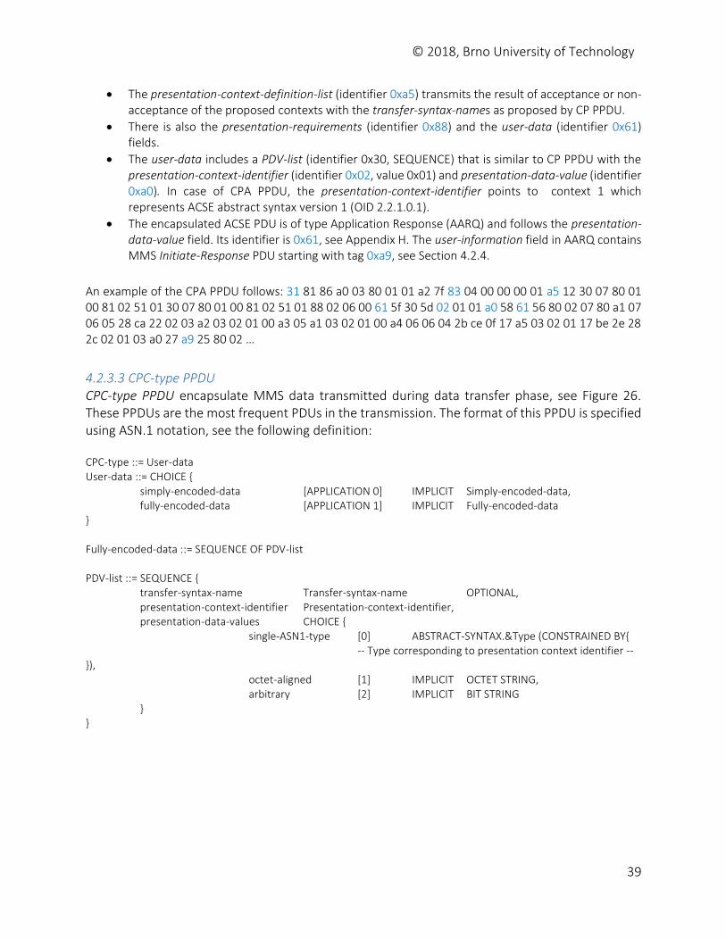
© 2018, Brno University of Technology
39
The presentation-context-definition-list (identifier 0xa5) transmits the result of acceptance or non-acceptance of the proposed contexts with the transfer-syntax-names as proposed by CP PPDU.
There is also the presentation-requirements (identifier 0x88) and the user-data (identifier 0x61) fields.
The user-data includes a PDV-list (identifier 0x30, SEQUENCE) that is similar to CP PPDU with the presentation-context-identifier (identifier 0x02, value 0x01) and presentation-data-value (identifier 0xa0). In case of CPA PPDU, the presentation-context-identifier points to context 1 which represents ACSE abstract syntax version 1 (OID 2.2.1.0.1).
The encapsulated ACSE PDU is of type Application Response (AARQ) and follows the presentation-data-value field. Its identifier is 0x61, see Appendix H. The user-information field in AARQ contains MMS Initiate-Response PDU starting with tag 0xa9, see Section 4.2.4.
An example of the CPA PPDU follows: 31 81 86 a0 03 80 01 01 a2 7f 83 04 00 00 00 01 a5 12 30 07 80 01 00 81 02 51 01 30 07 80 01 00 81 02 51 01 88 02 06 00 61 5f 30 5d 02 01 01 a0 58 61 56 80 02 07 80 a1 07 06 05 28 ca 22 02 03 a2 03 02 01 00 a3 05 a1 03 02 01 00 a4 06 06 04 2b ce 0f 17 a5 03 02 01 17 be 2e 28 2c 02 01 03 a0 27 a9 25 80 02 …
4.2.3.3 CPC-type PPDU CPC-type PPDU encapsulate MMS data transmitted during data transfer phase, see Figure 26. These PPDUs are the most frequent PDUs in the transmission. The format of this PPDU is specified using ASN.1 notation, see the following definition: CPC-type ::= User-data User-data ::= CHOICE { simply-encoded-data [APPLICATION 0] IMPLICIT Simply-encoded-data, fully-encoded-data [APPLICATION 1] IMPLICIT Fully-encoded-data } Fully-encoded-data ::= SEQUENCE OF PDV-list PDV-list ::= SEQUENCE { transfer-syntax-name Transfer-syntax-name OPTIONAL, presentation-context-identifier Presentation-context-identifier, presentation-data-values CHOICE { single-ASN1-type [0] ABSTRACT-SYNTAX.&Type (CONSTRAINED BY{ -- Type corresponding to presentation context identifier --}), octet-aligned [1] IMPLICIT OCTET STRING, arbitrary [2] IMPLICIT BIT STRING } }
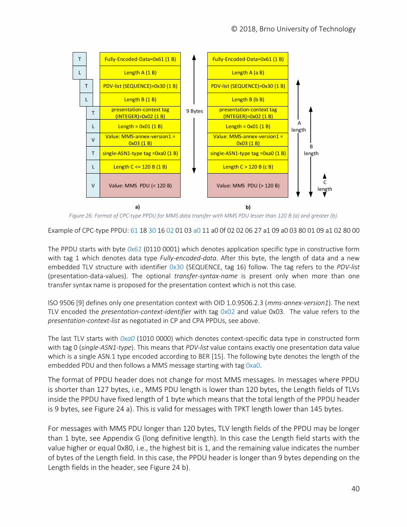
© 2018, Brno University of Technology
40
Fully-Encoded-Data=0x61 (1 B)
Length A (a B)
PDV-list (SEQUENCE)=0x30 (1 B)
Length B (b B)
presentation-context tag (INTEGER)=0x02 (1 B)
Length = 0x01 (1 B)
Value: MMS-annex-version1 = 0x03 (1 B)
single-ASN1-type tag =0xa0 (1 B)
Length C > 120 B (c B)
Value: MMS PDU (> 120 B)
T
L
T
L
T
L
V
T
L
V
Alength
Blength
C length
Fully-Encoded-Data=0x61 (1 B)
Length A (1 B)
PDV-list (SEQUENCE)=0x30 (1 B)
Length B (1 B)
presentation-context tag (INTEGER)=0x02 (1 B)
Length = 0x01 (1 B)
Value: MMS-annex-version1 = 0x03 (1 B)
single-ASN1-type tag =0xa0 (1 B)
Length C <= 120 B (1 B)
Value: MMS PDU (< 120 B)
9 Bytes
a) b) Figure 26: Format of CPC-type PPDU for MMS data transfer with MMS PDU lesser than 120 B (a) and greater (b).
Example of CPC-type PPDU: 61 18 30 16 02 01 03 a0 11 a0 0f 02 02 06 27 a1 09 a0 03 80 01 09 a1 02 80 00
The PPDU starts with byte 0x61 (0110 0001) which denotes application specific type in constructive form with tag 1 which denotes data type Fully-encoded-data. After this byte, the length of data and a new embedded TLV structure with identifier 0x30 (SEQUENCE, tag 16) follow. The tag refers to the PDV-list (presentation-data-values). The optional transfer-syntax-name is present only when more than one transfer syntax name is proposed for the presentation context which is not this case. ISO 9506 [9] defines only one presentation context with OID 1.0.9506.2.3 (mms-annex-version1). The next TLV encoded the presentation-context-identifier with tag 0x02 and value 0x03. The value refers to the presentation-context-list as negotiated in CP and CPA PPDUs, see above. The last TLV starts with 0xa0 (1010 0000) which denotes context-specific data type in constructed form with tag 0 (single-ASN1-type). This means that PDV-list value contains exactly one presentation data value which is a single ASN.1 type encoded according to BER [15]. The following byte denotes the length of the embedded PDU and then follows a MMS message starting with tag 0xa0.
The format of PPDU header does not change for most MMS messages. In messages where PPDU is shorter than 127 bytes, i.e., MMS PDU length is lower than 120 bytes, the Length fields of TLVs inside the PPDU have fixed length of 1 byte which means that the total length of the PPDU header is 9 bytes, see Figure 24 a). This is valid for messages with TPKT length lower than 145 bytes. For messages with MMS PDU longer than 120 bytes, TLV length fields of the PPDU may be longer than 1 byte, see Appendix G (long definitive length). In this case the Length field starts with the value higher or equal 0x80, i.e., the highest bit is 1, and the remaining value indicates the number of bytes of the Length field. In this case, the PPDU header is longer than 9 bytes depending on the Length fields in the header, see Figure 24 b).
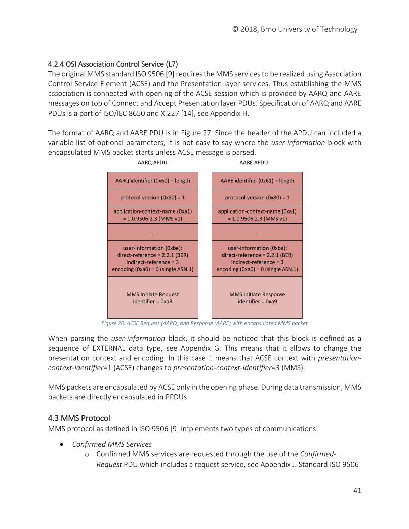
© 2018, Brno University of Technology
41
4.2.4 OSI Association Control Service (L7) The original MMS standard ISO 9506 [9] requires the MMS services to be realized using Association Control Service Element (ACSE) and the Presentation layer services. Thus establishing the MMS association is connected with opening of the ACSE session which is provided by AARQ and AARE messages on top of Connect and Accept Presentation layer PDUs. Specification of AARQ and AARE PDUs is a part of ISO/IEC 8650 and X.227 [14], see Appendix H. The format of AARQ and AARE PDU is in Figure 27. Since the header of the APDU can included a variable list of optional parameters, it is not easy to say where the user-information block with encapsulated MMS packet starts unless ACSE message is parsed.
application-context-name (0xa1)= 1.0.9506.2.3 (MMS v1)
MMS Initiate Requestidentifier = 0xa8
AARQ APDU AARE APDU
AARQ identifier (0x60) + length
protocol version (0x80) = 1
...
user-information (0xbe):direct-reference = 2.2.1 (BER)
indirect-reference = 3 encoding (0xa0) = 0 (single ASN.1)
application-context-name (0xa1)= 1.0.9506.2.3 (MMS v1)
MMS Initiate Responseidentifier = 0xa9
AARE identifier (0x61) + length
protocol version (0x80) = 1
...
user-information (0xbe):direct-reference = 2.2.1 (BER)
indirect-reference = 3 encoding (0xa0) = 0 (single ASN.1)
Figure 28: ACSE Request (AARQ) and Response (AARE) with encapsulated MMS packet
When parsing the user-information block, it should be noticed that this block is defined as a sequence of EXTERNAL data type, see Appendix G. This means that it allows to change the presentation context and encoding. In this case it means that ACSE context with presentation-context-identifier=1 (ACSE) changes to presentation-context-identifier=3 (MMS). MMS packets are encapsulated by ACSE only in the opening phase. During data transmission, MMS packets are directly encapsulated in PPDUs.
4.3 MMS Protocol MMS protocol as defined in ISO 9506 [9] implements two types of communications:
Confirmed MMS Services o Confirmed MMS services are requested through the use of the Confirmed-
Request PDU which includes a request service, see Appendix J. Standard ISO 9506
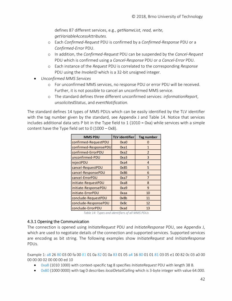
© 2018, Brno University of Technology
42
defines 87 different services, e.g., getNameList, read, write,
getVariableAccessAttributes.
o Each Confirmed-Request PDU is confirmed by a Confirmed-Response PDU or a
Confirmed-Error PDU.
o In addition, the Confirmed-Request PDU can be suspended by the Cancel-Request
PDU which is confirmed using a Cancel-Response PDU or a Cancel-Error PDU.
o Each instance of the Request PDU is correlated to the corresponding Response
PDU using the InvokeID which is a 32-bit unsigned integer.
Unconfirmed MMS Services
o For unconfirmed MMS services, no response PDU or error PDU will be received.
Further, it is not possible to cancel an unconfirmed MMS service.
o The standard defines three different unconfirmed services: informationReport,
unsolicitedStatus, and eventNotification.
The standard defines 14 types of MMS PDUs which can be easily identified by the TLV identifier with the tag number given by the standard, see Appendix J and Table 14. Notice that services includes additional data sets P bit in the Type field to 1 (1010 = 0xa) while services with a simple content have the Type field set to 0 (1000 – 0x8).
Table 14: Types and identifiers of all MMS PDUs
4.3.1 Opening the Communication The connection is opened using InitiateRequest PDU and InitiateResponse PDU, see Appendix J, which are used to negotiate details of the connection and supported services. Supported services are encoding as bit string. The following examples show InitiateRequest and InitiateResponse PDUs. Example 1: a8 26 80 03 00 fa 00 81 01 0a 82 01 0a 83 01 05 a4 16 80 01 01 81 03 05 e1 00 82 0c 03 a0 00 00 00 00 02 00 00 00 ed 10
0xa8 (1010 1000) with context-specific tag 8 specifies InitiateRequest PDU with length 38 B.
0x80 (1000 0000) with tag 0 describes localDetailCalling which is 3-byte integer with value 64.000.
MMS PDU TLV identifier Tag number
confirmed-RequestPDU 0xa0 0
confirmed-ResponsePDU 0xa1 1
confirmed-ErrorPDU 0xa2 2
unconfirmed-PDU 0xa3 3
rejectPDU 0xa4 4
cancel-RequestPDU 0x85 5
cancel-ResponsePDU 0x86 6
cancel-ErrorPDU 0xa7 7
initiate-RequestPDU 0xa8 8
initiate-ResponsePDU 0xa9 9
initiate-ErrorPDU 0xaa 10
conclude-RequestPDU 0x8b 11
conclude-ResponsePDU 0x8c 12
conclude-ErrorPDU 0xad 13
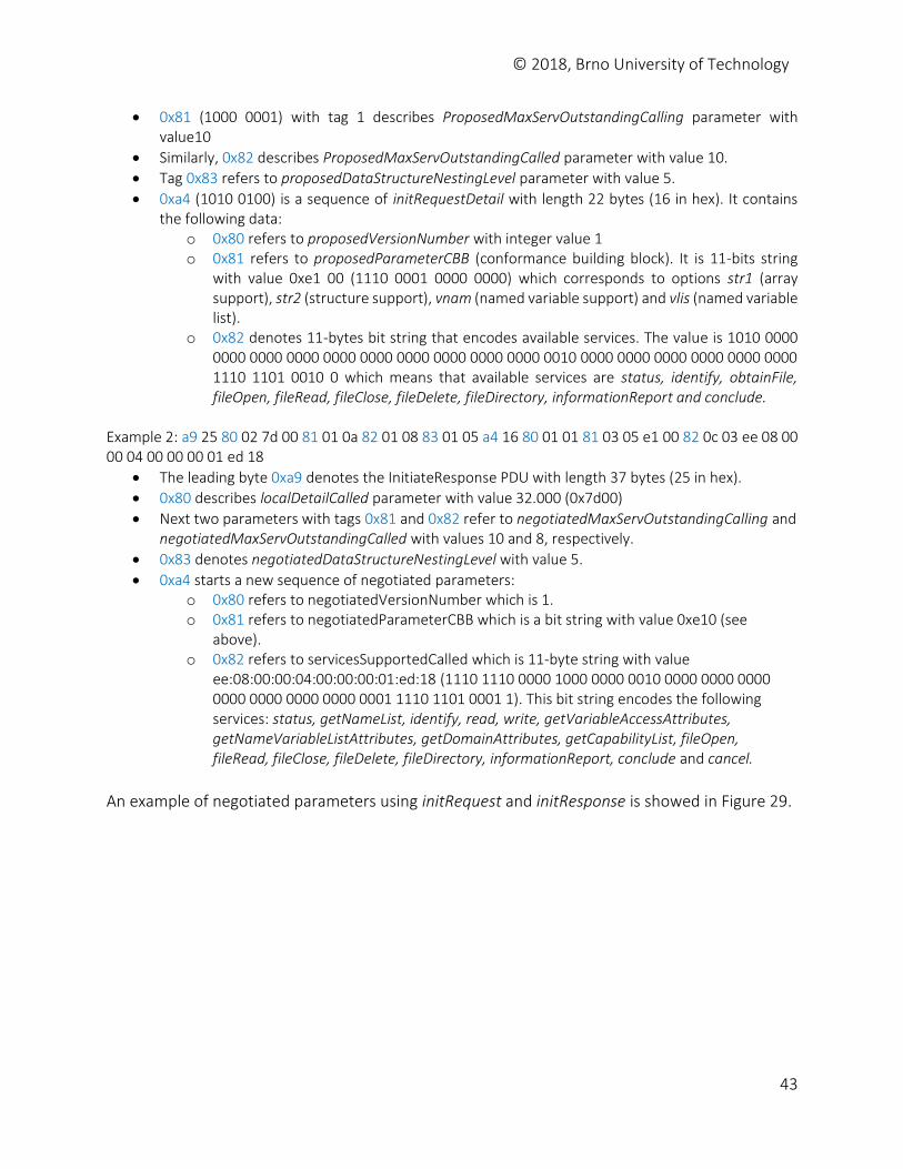
© 2018, Brno University of Technology
43
0x81 (1000 0001) with tag 1 describes ProposedMaxServOutstandingCalling parameter with value10
Similarly, 0x82 describes ProposedMaxServOutstandingCalled parameter with value 10.
Tag 0x83 refers to proposedDataStructureNestingLevel parameter with value 5.
0xa4 (1010 0100) is a sequence of initRequestDetail with length 22 bytes (16 in hex). It contains the following data:
o 0x80 refers to proposedVersionNumber with integer value 1 o 0x81 refers to proposedParameterCBB (conformance building block). It is 11-bits string
with value 0xe1 00 (1110 0001 0000 0000) which corresponds to options str1 (array support), str2 (structure support), vnam (named variable support) and vlis (named variable list).
o 0x82 denotes 11-bytes bit string that encodes available services. The value is 1010 0000 0000 0000 0000 0000 0000 0000 0000 0000 0000 0010 0000 0000 0000 0000 0000 0000 1110 1101 0010 0 which means that available services are status, identify, obtainFile, fileOpen, fileRead, fileClose, fileDelete, fileDirectory, informationReport and conclude.
Example 2: a9 25 80 02 7d 00 81 01 0a 82 01 08 83 01 05 a4 16 80 01 01 81 03 05 e1 00 82 0c 03 ee 08 00 00 04 00 00 00 01 ed 18
The leading byte 0xa9 denotes the InitiateResponse PDU with length 37 bytes (25 in hex).
0x80 describes localDetailCalled parameter with value 32.000 (0x7d00)
Next two parameters with tags 0x81 and 0x82 refer to negotiatedMaxServOutstandingCalling and negotiatedMaxServOutstandingCalled with values 10 and 8, respectively.
0x83 denotes negotiatedDataStructureNestingLevel with value 5.
0xa4 starts a new sequence of negotiated parameters: o 0x80 refers to negotiatedVersionNumber which is 1. o 0x81 refers to negotiatedParameterCBB which is a bit string with value 0xe10 (see
above). o 0x82 refers to servicesSupportedCalled which is 11-byte string with value
ee:08:00:00:04:00:00:00:01:ed:18 (1110 1110 0000 1000 0000 0010 0000 0000 0000 0000 0000 0000 0000 0001 1110 1101 0001 1). This bit string encodes the following services: status, getNameList, identify, read, write, getVariableAccessAttributes, getNameVariableListAttributes, getDomainAttributes, getCapabilityList, fileOpen, fileRead, fileClose, fileDelete, fileDirectory, informationReport, conclude and cancel.
An example of negotiated parameters using initRequest and initResponse is showed in Figure 29.
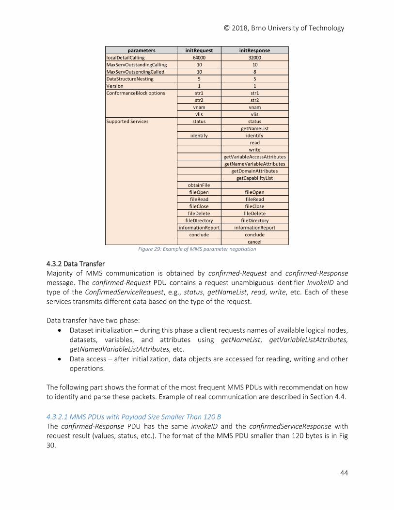
© 2018, Brno University of Technology
44
Figure 29: Example of MMS parameter negotiation
4.3.2 Data Transfer Majority of MMS communication is obtained by confirmed-Request and confirmed-Response message. The confirmed-Request PDU contains a request unambiguous identifier InvokeID and type of the ConfirmedServiceRequest, e.g., status, getNameList, read, write, etc. Each of these services transmits different data based on the type of the request. Data transfer have two phase:
Dataset initialization – during this phase a client requests names of available logical nodes, datasets, variables, and attributes using getNameList, getVariableListAttributes, getNamedVariableListAttributes, etc.
Data access – after initialization, data objects are accessed for reading, writing and other operations.
The following part shows the format of the most frequent MMS PDUs with recommendation how to identify and parse these packets. Example of real communication are described in Section 4.4.
4.3.2.1 MMS PDUs with Payload Size Smaller Than 120 B The confirmed-Response PDU has the same invokeID and the confirmedServiceResponse with request result (values, status, etc.). The format of the MMS PDU smaller than 120 bytes is in Fig 30.
parameters initRequest initResponselocalDetailCalling 64000 32000
MaxServOutstandingCalling 10 10
MaxServOutsendingCalled 10 8
DataStructureNesting 5 5
Version 1 1
str1 str1
str2 str2
vnam vnam
vlis vlis
status status
getNameList
identify identify
read
write
getVariableAccessAttributes
getNameVariableAttributes
getDomainAttributes
getCapabilityList
obtainFile
fileOpen fileOpen
fileRead fileRead
fileClose fileClose
fileDelete fileDelete
fileDIrectory fileDirectory
informationReport informationReport
conclude conclude
cancel
Supported Services
ConformanceBlock options
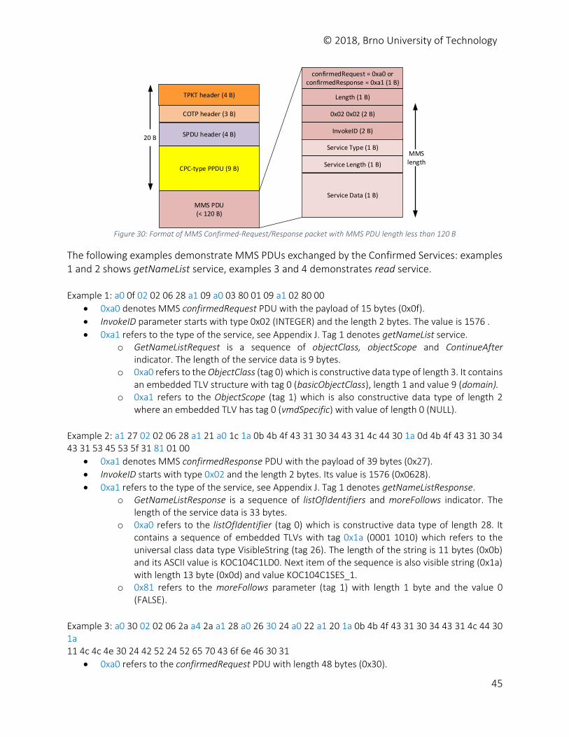
© 2018, Brno University of Technology
45
COTP header (3 B)
SPDU header (4 B)
CPC-type PPDU (9 B)
MMS PDU(< 120 B)
TPKT header (4 B)
20 B
confirmedRequest = 0xa0 or confirmedResponse = 0xa1 (1 B)
Length (1 B)
0x02 0x02 (2 B)
Service Type (1 B)
Service Length (1 B)
Service Data (1 B)
MMS length
InvokeID (2 B)
Figure 30: Format of MMS Confirmed-Request/Response packet with MMS PDU length less than 120 B
The following examples demonstrate MMS PDUs exchanged by the Confirmed Services: examples 1 and 2 shows getNameList service, examples 3 and 4 demonstrates read service. Example 1: a0 0f 02 02 06 28 a1 09 a0 03 80 01 09 a1 02 80 00
0xa0 denotes MMS confirmedRequest PDU with the payload of 15 bytes (0x0f).
InvokeID parameter starts with type 0x02 (INTEGER) and the length 2 bytes. The value is 1576 .
0xa1 refers to the type of the service, see Appendix J. Tag 1 denotes getNameList service. o GetNameListRequest is a sequence of objectClass, objectScope and ContinueAfter
indicator. The length of the service data is 9 bytes. o 0xa0 refers to the ObjectClass (tag 0) which is constructive data type of length 3. It contains
an embedded TLV structure with tag 0 (basicObjectClass), length 1 and value 9 (domain). o 0xa1 refers to the ObjectScope (tag 1) which is also constructive data type of length 2
where an embedded TLV has tag 0 (vmdSpecific) with value of length 0 (NULL).
Example 2: a1 27 02 02 06 28 a1 21 a0 1c 1a 0b 4b 4f 43 31 30 34 43 31 4c 44 30 1a 0d 4b 4f 43 31 30 34 43 31 53 45 53 5f 31 81 01 00
0xa1 denotes MMS confirmedResponse PDU with the payload of 39 bytes (0x27).
InvokeID starts with type 0x02 and the length 2 bytes. Its value is 1576 (0x0628).
0xa1 refers to the type of the service, see Appendix J. Tag 1 denotes getNameListResponse. o GetNameListResponse is a sequence of listOfIdentifiers and moreFollows indicator. The
length of the service data is 33 bytes. o 0xa0 refers to the listOfIdentifier (tag 0) which is constructive data type of length 28. It
contains a sequence of embedded TLVs with tag 0x1a (0001 1010) which refers to the universal class data type VisibleString (tag 26). The length of the string is 11 bytes (0x0b) and its ASCII value is KOC104C1LD0. Next item of the sequence is also visible string (0x1a) with length 13 byte (0x0d) and value KOC104C1SES_1.
o 0x81 refers to the moreFollows parameter (tag 1) with length 1 byte and the value 0 (FALSE).
Example 3: a0 30 02 02 06 2a a4 2a a1 28 a0 26 30 24 a0 22 a1 20 1a 0b 4b 4f 43 31 30 34 43 31 4c 44 30 1a 11 4c 4c 4e 30 24 42 52 24 52 65 70 43 6f 6e 46 30 31
0xa0 refers to the confirmedRequest PDU with length 48 bytes (0x30).
© 2018, Brno University of Technology
46
0x02 denotes InvokeID with value 1578 (0x06 2a).
0xa4 refers to the read service (tag 4). The length of service data is 42 bytes. The Read-Request is a sequence.
o 0xa1 means VariableAccessSpecification type with length 40 bytes (0x28). It contains another TLV structure with type 0xa0 (listOfVariables) with length 38 bytes (0x26).
o 0x30 denotes universal data type SEQUENCE (tag 16) of VariableSpecification with length 36 bytes.
o 0xa0 refers to the choice name (tag 0) which is another TLV called ObjectName. o 0xa1 denotes the domain-specific type which is a structure (SEQUENCE) of two items:
domainID and itemID. The first embedded TLV with tag 0x1a is Visible String of length 11 bytes (0xb) and
with value KOC104C1LD0. The following embedded TLV starts with tag 0x1a (Visible String) with length 17
bytes (0x11) and value LLN0$BR$RepConF01.
Example 4: a1 65 02 02 06 2a a4 5f a1 5d a2 5b 8a 0c 4d 41 4d 45 5f 52 65 70 43 6f 6e 46 83 01 00 8a 1a 4b 4f 43 31 30 34 43 31 4c 44 30 2f 4c 4c 4e 30 24 53 74 61 74 4e 72 6d 6c 44 86 01 01 84 03 06 00 03 86 02 01 f4 86 01 00 84 02 02 64 86 01 00 83 01 00 83 01 00 89 08 00 00 00 00 00 00 00 00 8c 06 00 00 00 00 00 00
0xa1 refers to the confirmedResponse PDU with length 101 bytes.
0x02 denotes InvokeID with value 1578 (0x06 2a). 0xa4 refers to the read service (tag 4). The ReadResponse is a sequence of
variableAccessSpecification (which is optional) and listOfAcccessResult. o 0xa1 denotes the listOfAccessResults. It is a sequence of AccessResults.
0xa2 refers to the successful result and Data type structure (tag 2). It is a sequence of Data with length 91 bytes.
0x8a is a VISIBLE string (context-specific tag 10). Its length is 12 and the value MAME_RepConF.
0x83 is a BOOLEAN with length 1 byte and value 0 (FALSE)
0x8a is another VISIBLE string with length 26 bytes and value KOC104C1LD0/LLN0$StatNrmlD.
0x86 is an integer of length 1 byte and value 1.
0x84 is a BIT STRING with length 3 bytes and value 0.
0x86 starts another integer of length 2 and value 500.
0x86 starts another integer of length 1 byte and value 0.
0x84 starts another BIT STRING with length 2 bytes and value 25.
0x86 starts another integer of length 1 byte and value 0.
0x83 is another BOOLEAN of length 1 byte and value 0 (FALSE).
0x83 is another BOOLEAN of length 1 byte and value 0 (FALSE).
0x89 starts an OCTET STRING of length 8 bytes and value 0x00 00 00 00.
0x8c is a TimeOfDay with length 6 bytes and value 0x00 00 00.
4.3.2.2 MMS PDUs with Payload Size Greater Than 120 B The above written messages transmit MMS packets lower than 120 bytes. In this case, a TLV structure in PPDU has length 1 byte, see Figure 26, and the total length of L5-L7 headers is 20 bytes. Thus, it is not difficult to find a starting point for MMS message parsing:
© 2018, Brno University of Technology
47
Destination port is 102 (ISO TSAP Class 0) o The destination port is not sufficient to prove that it is a MMS packet. Additional
checks shall be done: TPDU code of COTP shall be 0xf0 for COTP Data (offset 5 bytes from the
beginning of the TCP payload) SPDU type shall be 0x01 (Give Tokens) on L5 (offset 7 bytes from the
beginning of the TCP payload) PPDU type shall be 0x61 (CPC-type PPDU) on L6 (offset 11 bytes from the
beginning of the TCP payload) MMS type for confirmed services shall be 0xa0 (Request) or 0xa1
(Response) on L7 (offset 20 bytes from the beginning of the TCP payload)
The length of TCP payload shall be less than 140 bytes. Since the TCP header does not contain the length of the content, it is possible to use TPKT length which is a 2-bytes value inserted at the beginning of the TCP payload (offset 2 bytes from the beginning of the TCP payload). Thus, the TPKT length shall be less than 136 bytes.
o By analyzing available datasets, the majority of MMS confirmed PDUs (cca 89%) fall into this category, see Section 4.4.
In case that the length of the MMS payload is greater or equal to 120 bytes, length fields in TLV structure in PPDU will be longer than 1 byte, see Figure 26 b). In such case, the beginning of PPDU can be easily found using the offset 7 bytes from the beginning of the TCP payload. Then, PPDU should be parsed so that the beginning of MMS message can be found.
o However, this happens only when longer data are requested, see the following requests: getVariableAccessAttributes, getNamedVariableListAttributes.
o Analysis of datasets shows that only 5% of MMS confirmed PDUs have length greater than 120 Bytes, see Section 4.4.
The following examples show MMS request for getVariableAccessAttributes. The message is shorter than 120 Bytes, thus it can be easily parsed. However, the answer transmits more data than 120 bytes, thus the PPDU has not fixed size and each TLV shall be parsed to find the beginning of MMS message. Example 5: a0 2a 02 02 06 28 a6 24 a0 22 a1 20 1a 0b 4b 4f 43 31 30 34 43 31 4c 44 30 1a 11 4c 4c 4e 30 24 42 52 24 52 65 70 43 6f 6e 43 30 32
0xa0 refers to the confirmedRequest PDU with length 42 bytes (0x2a).
0x02 denotes InvokeID with value 1576 (0x06 26).
0xa6 refers to the getVariableAccessAttributes service (tag 6). The length of service data is 36 bytes. The getVariableAccessAttributes-Request is a sequence.
o 0xa0 refers to the choice name (tag 0) which is another TLV called ObjectName. o 0xa1 denotes the domain-specific type which is a structure (SEQUENCE) of two items:
domainID and itemID. The first embedded TLV with tag 0x1a is Visible String of length 11 bytes (0xb) and
with value KOC104C1LD0.
© 2018, Brno University of Technology
48
The following embedded TLV starts with tag 0x1a (Visible String) with length 17 bytes (0x11) and value LLN0$BR$RepConC02.
The following answer will be analyzed starting at presentation layer. Example 6: 61 81 e2 30 81 df 02 01 03 a0 81 d9 a1 81 d6 02 02 06 28 a6 81 cf 80 01 00 a2 81 c9 a2 81 c6 a1 81 c3 30 0c 80 05 52 70 74 49 44 a1 03 8a 01 bf 30 0c 80 06 52 70 74 45 6e 61 a1 02 83 00 30 0d 80 06 …
0x61 starts a CPC-type PDU with length 226 bytes (0xe2). Byte 0x81 indicates that the Length field in this TLV has the long format with length 1 bytes.
0x30 indicates a PDV-list which is a SEQUENCE. Its length is 223 Bytes (0xdf) o 0x02 represents the presentation-context-identifier which is 3. o 0xa0 starts the single-ASN1-type field which contains a MMS message with the payload of
217 bytes (0xd9). Here, we can see that the Length fields in TLV structures in the MMS PDU have also the long format.
o 0xa1 refers to confirmed-Response PDU. The length of the PDU is 214 bytes (0xd6) 0x02 starts the InvokeID field with value 1576. 0xa6 refers to the getVariableAccessAttributes-Response service (tag 6). The
embedded structure is a SEQUENCE.
0x80 denotes mmsDeletable flag (tag 0) which is 0 (FALSE). 0xa2 refers to TypeDescription (tag 2) with length 201 bytes (0xc9) which
encapsulates another TLV structure. o 0xa2 refers to the Structure data type (tag 2) which is a
SEQUENCE. 0xa1 refers to the components which is a list of the componentName and componentType. These items are used to define data types with their new names and ASN.1 data types.
0x30 (0011 0000) denotes universal data type, constructive and SEQUENCE. Thus, each attribute will start with this tag. Following value with starting tag 0x80 refers to the EXTERNAL data type of length 5. The value is RptID (a new data type). The next item (componentType) starts with 0xa1 tag and length 3 bytes. 0x8a (1000 1010) refers to primitive context-specific data type with tag 10 which means visible-string. The value is 0xbf.
The next components sequence also starts with 0x30 byte, the length and the first item (componentName, tag 0x80). The value of the componentName is is RptEna. The second item (componentType, tag 0xa1) refers to the embedded TLV with type tag 0x83 (1000 0011) which indicates Boolean with length 0.
Similarly, we can analyze other attribute data types. The MMS PDU which size greater than 120 bytes usually has variable data structure on L6 (PPDU) and L7 (MMS). This is because TLV structure requires longer format of the Length field. However, parsing of the message can employ fixed values from L6 and L7 headers which do not depend on the payload size. Thus, the parser can use these values as marks when analyzing data structure, see Figure 31.
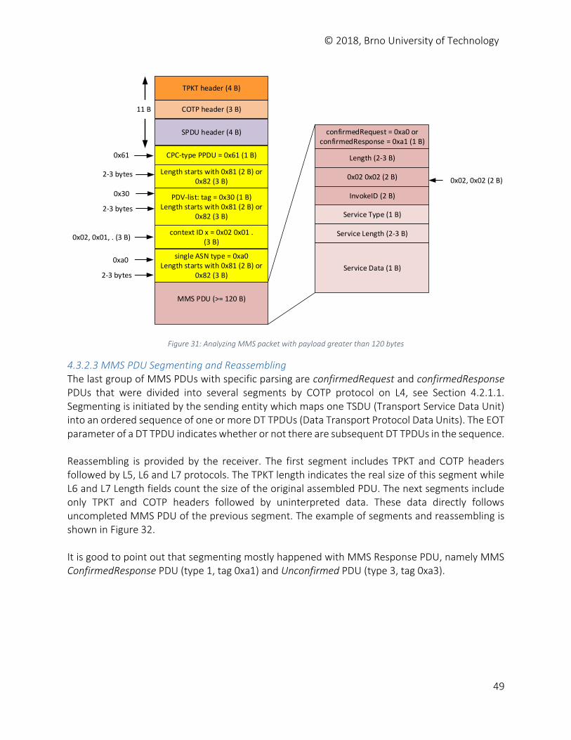
© 2018, Brno University of Technology
49
0x61
2-3 bytes
COTP header (3 B)
SPDU header (4 B)
CPC-type PPDU = 0x61 (1 B)
MMS PDU (>= 120 B)
TPKT header (4 B)
11 B
confirmedRequest = 0xa0 or confirmedResponse = 0xa1 (1 B)
Length (2-3 B)
0x02 0x02 (2 B)
Service Type (1 B)
Service Length (2-3 B)
Service Data (1 B)
InvokeID (2 B)
Length starts with 0x81 (2 B) or 0x82 (3 B)
PDV-list: tag = 0x30 (1 B)Length starts with 0x81 (2 B) or
0x82 (3 B)
0x30
2-3 bytes
context ID x = 0x02 0x01 . (3 B)
single ASN type = 0xa0Length starts with 0x81 (2 B) or
0x82 (3 B)
0x02, 0x01, . (3 B)
0xa0
2-3 bytes
0x02, 0x02 (2 B)
Figure 31: Analyzing MMS packet with payload greater than 120 bytes
4.3.2.3 MMS PDU Segmenting and Reassembling The last group of MMS PDUs with specific parsing are confirmedRequest and confirmedResponse PDUs that were divided into several segments by COTP protocol on L4, see Section 4.2.1.1. Segmenting is initiated by the sending entity which maps one TSDU (Transport Service Data Unit) into an ordered sequence of one or more DT TPDUs (Data Transport Protocol Data Units). The EOT parameter of a DT TPDU indicates whether or not there are subsequent DT TPDUs in the sequence. Reassembling is provided by the receiver. The first segment includes TPKT and COTP headers followed by L5, L6 and L7 protocols. The TPKT length indicates the real size of this segment while L6 and L7 Length fields count the size of the original assembled PDU. The next segments include only TPKT and COTP headers followed by uninterpreted data. These data directly follows uncompleted MMS PDU of the previous segment. The example of segments and reassembling is shown in Figure 32. It is good to point out that segmenting mostly happened with MMS Response PDU, namely MMS ConfirmedResponse PDU (type 1, tag 0xa1) and Unconfirmed PDU (type 3, tag 0xa3).
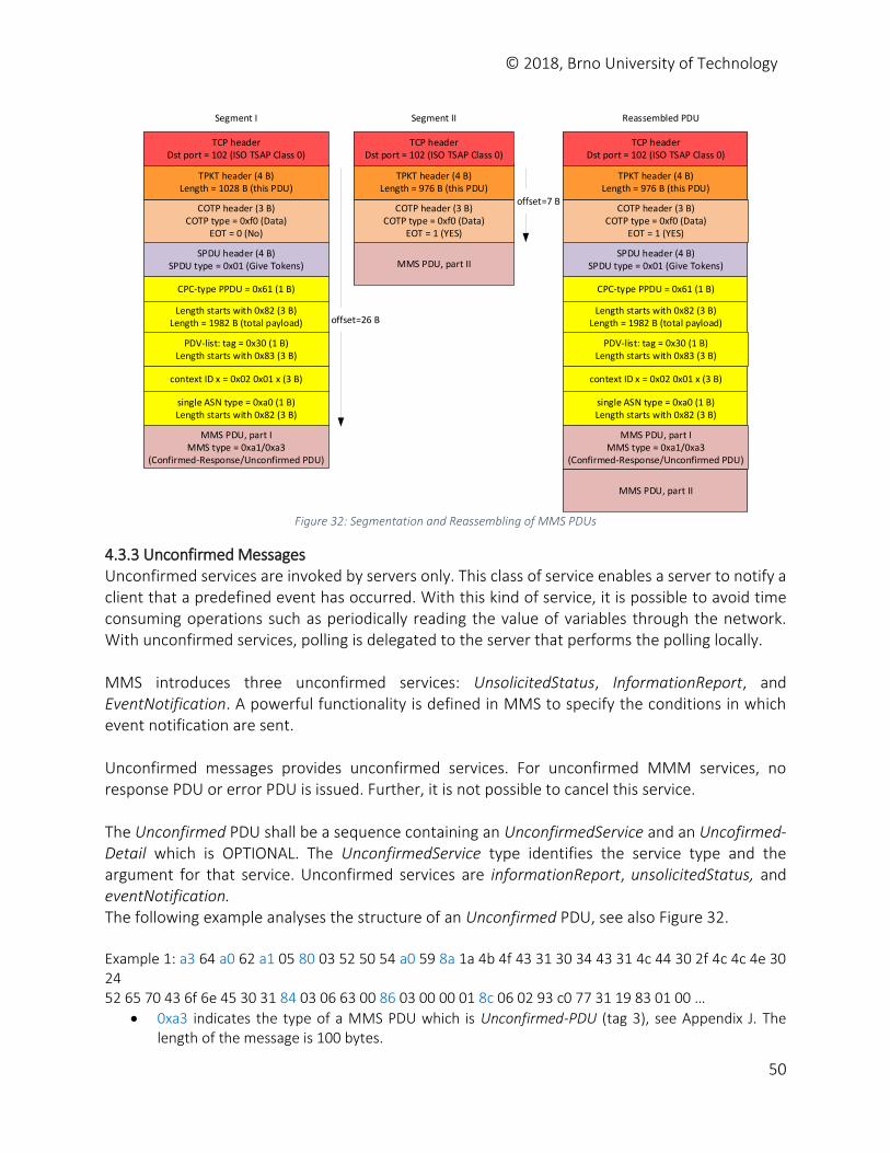
© 2018, Brno University of Technology
50
offset=26 B
offset=7 BCOTP header (3 B)
COTP type = 0xf0 (Data)EOT = 0 (No)
SPDU header (4 B)SPDU type = 0x01 (Give Tokens)
MMS PDU, part I MMS type = 0xa1/0xa3
(Confirmed-Response/Unconfirmed PDU)
TPKT header (4 B)Length = 1028 B (this PDU)
TCP header Dst port = 102 (ISO TSAP Class 0)
CPC-type PPDU = 0x61 (1 B)
Length starts with 0x82 (3 B)Length = 1982 B (total payload)
PDV-list: tag = 0x30 (1 B)Length starts with 0x83 (3 B)
context ID x = 0x02 0x01 x (3 B)
single ASN type = 0xa0 (1 B)Length starts with 0x82 (3 B)
COTP header (3 B)COTP type = 0xf0 (Data)
EOT = 1 (YES)
TPKT header (4 B)Length = 976 B (this PDU)
TCP header Dst port = 102 (ISO TSAP Class 0)
MMS PDU, part II
COTP header (3 B)COTP type = 0xf0 (Data)
EOT = 1 (YES)
SPDU header (4 B)SPDU type = 0x01 (Give Tokens)
TPKT header (4 B)Length = 976 B (this PDU)
TCP header Dst port = 102 (ISO TSAP Class 0)
CPC-type PPDU = 0x61 (1 B)
Length starts with 0x82 (3 B)Length = 1982 B (total payload)
PDV-list: tag = 0x30 (1 B)Length starts with 0x83 (3 B)
context ID x = 0x02 0x01 x (3 B)
single ASN type = 0xa0 (1 B)Length starts with 0x82 (3 B)
MMS PDU, part II
MMS PDU, part I MMS type = 0xa1/0xa3
(Confirmed-Response/Unconfirmed PDU)
Segment I Segment II Reassembled PDU
Figure 32: Segmentation and Reassembling of MMS PDUs
4.3.3 Unconfirmed Messages Unconfirmed services are invoked by servers only. This class of service enables a server to notify a client that a predefined event has occurred. With this kind of service, it is possible to avoid time consuming operations such as periodically reading the value of variables through the network. With unconfirmed services, polling is delegated to the server that performs the polling locally. MMS introduces three unconfirmed services: UnsolicitedStatus, InformationReport, and EventNotification. A powerful functionality is defined in MMS to specify the conditions in which event notification are sent. Unconfirmed messages provides unconfirmed services. For unconfirmed MMM services, no response PDU or error PDU is issued. Further, it is not possible to cancel this service. The Unconfirmed PDU shall be a sequence containing an UnconfirmedService and an Uncofirmed-Detail which is OPTIONAL. The UnconfirmedService type identifies the service type and the argument for that service. Unconfirmed services are informationReport, unsolicitedStatus, and eventNotification. The following example analyses the structure of an Unconfirmed PDU, see also Figure 32. Example 1: a3 64 a0 62 a1 05 80 03 52 50 54 a0 59 8a 1a 4b 4f 43 31 30 34 43 31 4c 44 30 2f 4c 4c 4e 30 24 52 65 70 43 6f 6e 45 30 31 84 03 06 63 00 86 03 00 00 01 8c 06 02 93 c0 77 31 19 83 01 00 …
0xa3 indicates the type of a MMS PDU which is Unconfirmed-PDU (tag 3), see Appendix J. The length of the message is 100 bytes.
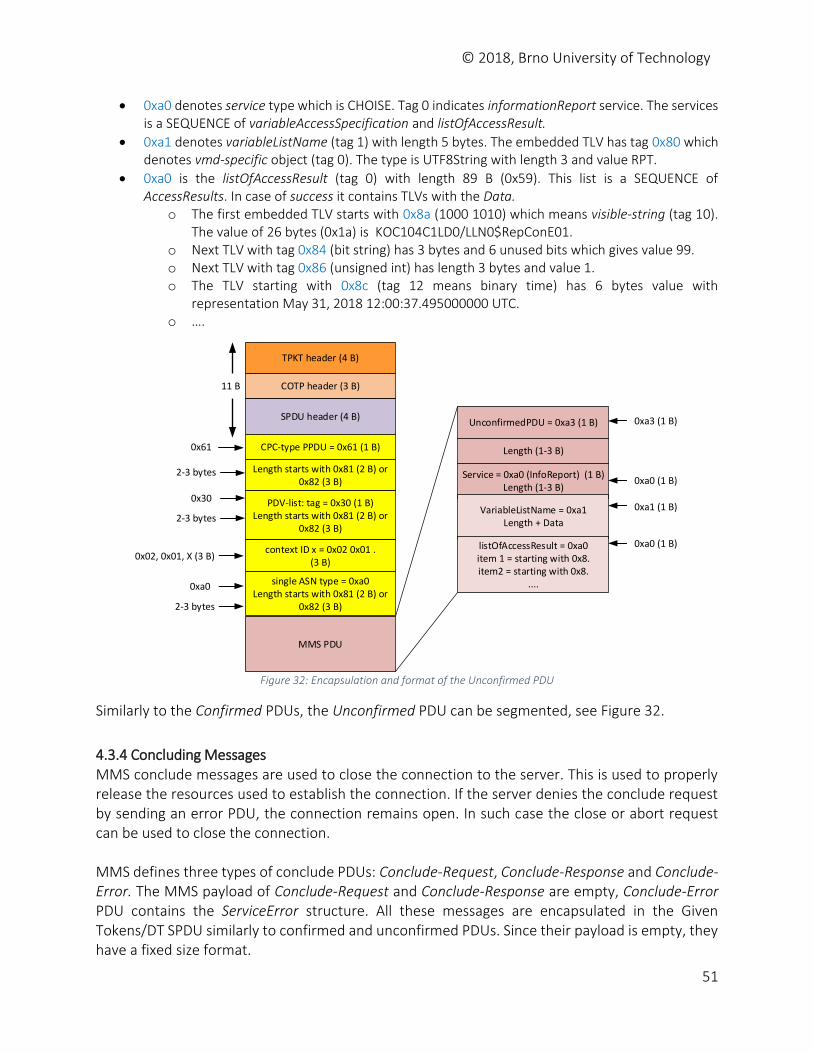
© 2018, Brno University of Technology
51
0xa0 denotes service type which is CHOISE. Tag 0 indicates informationReport service. The services is a SEQUENCE of variableAccessSpecification and listOfAccessResult.
0xa1 denotes variableListName (tag 1) with length 5 bytes. The embedded TLV has tag 0x80 which denotes vmd-specific object (tag 0). The type is UTF8String with length 3 and value RPT.
0xa0 is the listOfAccessResult (tag 0) with length 89 B (0x59). This list is a SEQUENCE of AccessResults. In case of success it contains TLVs with the Data.
o The first embedded TLV starts with 0x8a (1000 1010) which means visible-string (tag 10). The value of 26 bytes (0x1a) is KOC104C1LD0/LLN0$RepConE01.
o Next TLV with tag 0x84 (bit string) has 3 bytes and 6 unused bits which gives value 99. o Next TLV with tag 0x86 (unsigned int) has length 3 bytes and value 1. o The TLV starting with 0x8c (tag 12 means binary time) has 6 bytes value with
representation May 31, 2018 12:00:37.495000000 UTC. o ….
0x61
2-3 bytes
COTP header (3 B)
SPDU header (4 B)
CPC-type PPDU = 0x61 (1 B)
MMS PDU
TPKT header (4 B)
11 B
UnconfirmedPDU = 0xa3 (1 B)
Length (1-3 B)
Service = 0xa0 (InfoReport) (1 B)Length (1-3 B)
VariableListName = 0xa1Length + Data
Length starts with 0x81 (2 B) or 0x82 (3 B)
PDV-list: tag = 0x30 (1 B)Length starts with 0x81 (2 B) or
0x82 (3 B)
0x30
2-3 bytes
context ID x = 0x02 0x01 . (3 B)
single ASN type = 0xa0Length starts with 0x81 (2 B) or
0x82 (3 B)
0x02, 0x01, X (3 B)
0xa0
2-3 bytes
0xa0 (1 B)
0xa3 (1 B)
0xa1 (1 B)
listOfAccessResult = 0xa0item 1 = starting with 0x8.item2 = starting with 0x8.
....
0xa0 (1 B)
Figure 32: Encapsulation and format of the Unconfirmed PDU
Similarly to the Confirmed PDUs, the Unconfirmed PDU can be segmented, see Figure 32.
4.3.4 Concluding Messages MMS conclude messages are used to close the connection to the server. This is used to properly release the resources used to establish the connection. If the server denies the conclude request by sending an error PDU, the connection remains open. In such case the close or abort request can be used to close the connection. MMS defines three types of conclude PDUs: Conclude-Request, Conclude-Response and Conclude-Error. The MMS payload of Conclude-Request and Conclude-Response are empty, Conclude-Error PDU contains the ServiceError structure. All these messages are encapsulated in the Given Tokens/DT SPDU similarly to confirmed and unconfirmed PDUs. Since their payload is empty, they have a fixed size format.
© 2018, Brno University of Technology
52
The following examples show analysis of a Conclude-Request PDU and a Conclude-Response PDU. Example 1: 8b 00
Identifier 0x8b (1000 1011) defines application data type in primitive form with tag number 11 which means Conclude Request PDU. Its length is 0, i.e., no payload is present.
Example 2: 8c 00
Similarly, identifier 0x8c (1000 1100) denotes Conclude Response PDU with length 0, i.e., no data present.
4.4 Example of MMS Communication In this part available MMS datasets will be analyzed with the focus on security monitoring of MMS communication. We will analyze two datasets: mms.pcapng obtained from power system simulator in INPG Grenoble, and mms1.pcapng with real traffic from the commercial partner.
4.4.1 Dataset mms.pcapng This dataset contains 506 MMS packets captured within 5 minutes. Dataset contains one sequence of Initiate-Request – Initiate-Response PDUs and 504 confirmed-Request and confirmed-Response PDUs. PDUs are transmitted between two stations and encapsulated in TCP/IP protocols and uses A-Profile.
4.4.1.1 Connection Opening Connection is established using L4, L5, L6 and L7 protocols. On L4, TCP with destination port 102 opens connection. Session protocol (L5) sends Connect SPDU with Calling and Called Session Selectors. Presentation layer (L6) transmits CP PPDU with a list of defined presentation contexts: ACSE abstract syntax (OID 2.2.1.0.1) with identifier 1 and MMS abstract syntax (OID 1.0.9506.1) with identifier 2. Both contexts will be encoded using BER encoding (OID 2.1.1). On L 7, AARQ and AARE are exchanged with MMS initiate-Request and initiate-Response messages. In these messages, connection parameters are negotiated: number of maximal served peers, level of data structure nesting, protocol version, supported conformance parameters, and a list of supported services, see Table 11. The MMS initiate-Request is confirmed by initiate-Response PDU.
4.4.1.2 Dataset Initialization Next phases of communication are provided by sequences of confirmed-Request and confirmed-Response PDUs. The requests are bound with responses using InvokeID sequence number. The phases include data initialization and data access. Data initialization discovers available Virtual Manufacturing Devices (VMDs) on the destination physical device. For each VMD, a list of logical nodes, data objects, and attributes will be obtained using getNameList and getNamedVariableListAttributes services.
getNameList service (tag 0xa1) – 5x
© 2018, Brno University of Technology
53
o GetNameList service returns the names of all MMS objects. It can be selectively determined from which classes of objects (named variable, event condition) the names of the stored objects shall be queried. The client can browse a VMD (vmd scope) or a logical node (domain specific scope) and then systematically query all names of the objects.
o GetNameList request is done only once for each logical device (MMS domain) and the results are cached in the client for later calls.
o These requests and responses were sent just after the connection was established. o The first request queries all domains (logical nodes) on the given VMD: objectClass
is of type 9 (domain) and objectScope type is 0 (vmdSpecific). It is some kind of LN discovery.
o As the response, a list of four identifiers (logical nodes, or MMS domains) is returned: SIPCTRL, SIPDR, SIPMEAS, and SIPPROT.
o The following getNameList requests query named variables on the previously discovered logical nodes (MMS domains). Thus, the sent requests contain objectClass of type 2 (nameVariableList) for each of the above specified MMS domains, i.e., SIPCTRL, SIPDR, SIPMEAS, and SIPPROT. The response for SIPCTRL contained two identifiers (VMD names): LLN0$Dataset and LLN0$Dataset_1_1. The responses for SIPDR and SIPMEAS did not contain any data object. The response for SIPPROT contained one VMD object with identifier LLN0$Dataset_1.
getNamedVariableListAttributes (tag 0xac) – 3x o Following getNameList requests, getNameVariableListAttributes requests are sent
for discovered logical nodes and data objects, i.e., for LN SIPCTRL and object LLN0$Dataset, for LN SIPCTRL and object LLN0$Dataset_1_1, and for LN SIPPROT and domain LLN0$Dataset_1.
o The following attributes were discovered: for SIPCTRL and item LLN0$Dataset attributes XSWI1$ST$Pos$stVal and XSWI1$ST$Pos$q. The names are data object references, see Section 2.1.6 which refers to the logical node XSWI1 (switch without short circuit breaking capability [7]). Data object Pos (switch position) belongs to CDC called DPC (controllable double point) which contains attributes stVal (status value) and q (quality) [5].
o Similarly, for SIPCTRL and objects LLN0$Dataset_1_1 two attribute references were found: XCBR1$ST$TripOpnCmd$stVal and XCBR1$ST$TripOpnCmd$q. These refer to XCBR class (circuit breaker with short breaking capability), functional group status, non-standard data object TripOpnCmd and attributes stVal (status) and q (quality).
o The last attribute references were obtained from SIPPROT logical node and VMD LLN0$Dataset_1: ID_PTOC1$ST$Str$general and ID_PTOC1$ST$Str$q. These refer to data object Str (start) and attributes general and quality. Object Str belongs to CDC called ACD (Directional protection activation information).
4.4.1.3 Data Access Following data initialization, discovered logical nodes are queried for updates. A special attributes called LLN0$DC$NamPlt$configRev is regularly checked. The attribute belongs to the logical node LLN0 which administers a given VMD. NamePlt (name plate of the logical device) refers to class
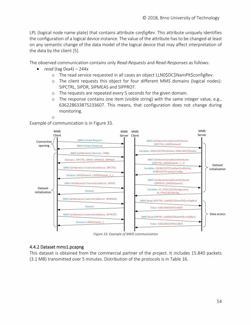
© 2018, Brno University of Technology
54
LPL (logical node name plate) that contains attribute configRev. This attribute uniquely identifies the configuration of a logical device instance. The value of the attribute has to be changed at least on any semantic change of the data model of the logical device that may affect interpretation of the data by the client [5]. The observed communication contains only Read-Requests and Read-Responses as follows:
read (tag 0xa4) – 244x o The read service requested in all cases an object LLN0$DC$NamPlt$configRev. o The client requests this object for four different MMS domains (logical nodes):
SIPCTRL, SIPDR, SIPMEAS and SIPPROT. o The requests are repeated every 5 seconds for the given domain. o The response contains one item (visible string) with the same integer value, e.g.,
636228633875233607. This means, that configuration does not change during monitoring.
o Example of communication is in Figure 33.
MMS Server
MMS Initiate Request
MMS Initiate Response
MMS GetNameList (domain, VMD)
Domains: SIPCTRL, SIPDR, SIPMEAS, SIPPROT
MMS GetNameList (nameVariableList, SIPCTRL)
Dataset:LLN0$Dataset, LLN0$Dataset_1_1
MMS GetNameList (nameVariableList, SIPDR)
Dataset:
MMS GetNameList (nameVariableList, SIPMEAS)
Dataset:
MMS GetNameList (nameVariableList, SIPPROT)
Dataset:LLN0$Dataset_1
MMS Client
MMS GetNameVariableListAttributes (SIPCTRL,LLN0$Dataset)
Variables: XSWI1$ST$Pos$stVal, XSWI1$SST$Pos$q
MMS GetNameVariableListAttributes (SIPCTRL,LLN0$Dataset_1_1)
Variables: XSCBR1$ST$TripOpnCmd$stVal, XCBR1$ST$TripOpnCmd$q
MMS GetNameVariableListAttributes (SIPPROT,LLN0$Dataset1)
Variables: ID_PT0C1$ST$Str$general, ID_PT0C1$ST$Str$q
MMS Read (SIPCTRL, LLN0$DC$NamPlt$configRev)
Value: 636228633875233607
MMS Read (SIPDR, LLN0$DC$NamPlt$configRev)
Value: 636228633879213835
Dataset initialization
Data access
Connection opening
Dataset initialization
MMS Client
MMS Server
Figure 33: Example of MMS communication
4.4.2 Dataset mms1.pcapng This dataset is obtained from the commercial partner of the project. It includes 15.840 packets (3.1 MB) transmitted over 5 minutes. Distribution of the protocols is in Table 16.
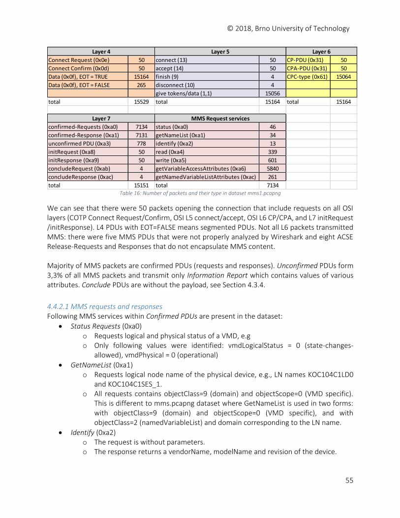
© 2018, Brno University of Technology
55
Table 16: Number of packets and their type in dataset mms1.pcapng
We can see that there were 50 packets opening the connection that include requests on all OSI layers (COTP Connect Request/Confirm, OSI L5 connect/accept, OSI L6 CP/CPA, and L7 initRequest /initResponse). L4 PDUs with EOT=FALSE means segmented PDUs. Not all L6 packets transmitted MMS: there were five MMS PDUs that were not properly analyzed by Wireshark and eight ACSE Release-Requests and Responses that do not encapsulate MMS content. Majority of MMS packets are confirmed PDUs (requests and responses). Unconfirmed PDUs form 3,3% of all MMS packets and transmit only Information Report which contains values of various attributes. Conclude PDUs are without the payload, see Section 4.3.4.
4.4.2.1 MMS requests and responses Following MMS services within Confirmed PDUs are present in the dataset:
Status Requests (0xa0) o Requests logical and physical status of a VMD, e.g o Only following values were identified: vmdLogicalStatus = 0 (state-changes-
allowed), vmdPhysical = 0 (operational)
GetNameList (0xa1) o Requests logical node name of the physical device, e.g., LN names KOC104C1LD0
and KOC104C1SES_1. o All requests contains objectClass=9 (domain) and objectScope=0 (VMD specific).
This is different to mms.pcapng dataset where GetNameList is used in two forms: with objectClass=9 (domain) and objectScope=0 (VMD specific), and with objectClass=2 (namedVariableList) and domain corresponding to the LN name.
Identify (0xa2) o The request is without parameters. o The response returns a vendorName, modelName and revision of the device.
Connect Request (0x0e) 50 connect (13) 50 CP-PDU (0x31) 50
Connect Confirm (0x0d) 50 accept (14) 50 CPA-PDU (0x31) 50
Data (0x0f), EOT = TRUE 15164 finish (9) 4 CPC-type (0x61) 15064
Data (0x0f), EOT = FALSE 265 disconnect (10) 4
give tokens/data (1,1) 15056
total 15529 total 15164 total 15164
confirmed-Requests (0xa0) 7134 status (0xa0) 46
confirmed-Response (0xa1) 7131 getNameList (0xa1) 34
unconfirmed PDU (0xa3) 778 identify (0xa2) 13
initRequest (0xa8) 50 read (0xa4) 339
initResponse (0xa9) 50 write (0xa5) 601
concludeRequest (0xab) 4 getVariableAccessAttributes (0xa6) 5840
concludeResponse (0xac) 4 getNamedVariableListAttributes (0xac) 261
total 15151 total 7134
Layer 4 Layer 5 Layer 6
Layer 7 MMS Request services
© 2018, Brno University of Technology
56
o For this dataset, following values were discovered: vendor = ABB AB, model = IEC 8-1 Server, revision = V1.80.00.04p.
Read (0xa4) o Reads value of a given list of variables. The ReadRequest contains a domainID
(logical device name), e.g., KOC101C1LD0, and a listOfVariables structure identified by object reference, e.g., LLN0$BR$RepConG03$RptEna.
o The ReadRequest may contain one or more variables to be read. In our dataset, the requests contain 1, 6, or 11 variables to be retrieved.
o For each requested variable, the ReadResponse contains the success bit and the value of the variable. E.g., for the requested variable LLN0$BR$RepConA03$RptEna a Boolean value FALSE is returned.
Write (0xa5) o The service sets values of a given list of variables. The WriteRequest transmits a list
of variables which contains domain IDs and variable names for all requested variables. Following that is a list of data which contains values to be set. E.g., domainID=KOC104C1LD0, LLN0$BR$RepConF01$BufTm, value=500 (unsigned int).
o The WriteResponse returns a list of write results, e.g., success (1).
GetVariableAccessAttributes (0xa6) o The request retrieves MMS type specification for given domain and object, e.g.,
domainID=KOC104C1LD0, data object=SP16GGIO1$ST$Ind11. o The response contain the type specifications related to this object, e.g.,
name=stVal, type=boolean, name=q, type=bitstring
GetNamedVariableListAttributes (0xac) o Requests available attributes (variables) in the given dataset. The request specifies
a domain and the logical node (dataset), e.g., KOC104C1LD0, LLN0$StatNrmlD. o The response returns a list of attributes (variables) in the requested dataset, e.g.,
SP16GGIO9$ST$Ind6, SP16GGIO9$ST$Ind7, etc. o In our dataset, the list contains up to 50 variables.
4.4.2.2 Conversations The captured communication contains 20 end points on L2 and L3 layer which include 3 MMS clients requesting services and 17 MMS servers (IEDs). We can see that each client requests several MMS servers. Example of conversation between 10.164.253.207 (MMS client) and 10.164.253.6 (MMS server):
1. Connection is opened using MMS initiate Request and MMS initiate Response. 2. Dataset initialization
i. MMS identify service is requested by the client.
The response include description of the server: vendor (ABB AB), model name (IEC 8-1 server), and revision (V1.80.00.04p).
ii. MMS read variable: domain= KOC171C1LD0, variable= LLN0$DC$NamPlt$configRev
MMS read response: 3311665 iii. MMS getNamedVariableListAttributes, domain= KOC171C1LD0, LN= LLN0$StatIEDA
MMS response: attribute= LPHD1$ST$PhyHealth
© 2018, Brno University of Technology
57
iv. MMS getVariableAccessAttributes, domain= KOC171C1LD0, LN= LPHD1$ST$PhyHealth
MMS response: name=stVal, type=integer, name=q, type=q v. MMS getNamedVariableAccessAttributes, domain= KOC171C1LD0, LN= LLN0$StatUrgA
MMS response: 48 variables (domain ID + variable name), e.g., SCSWI1$ST$Pos, SCSWI10$ST$Pos, SCSWI11$ST$Pos, SCSWI2$ST$Pos, …
vi. MMS getVariableAccessAttributes for previous variables, domain= KOC171C1LD0, LN= SXSWI1$ST$Pos
MMS response: stVal (bit-string)=2, q (bit-string)=13 vii. MMS getNamedVariableListAttributes, domain= KOC171C1LD0, LN= LLN0$StatNrmlA
MMS response: 50 variables (domain ID + variable name), e.g., SP16GGIO1$ST$Ind, SP16GGIO1$ST$Ind10, etc.
viii. MMS getNamedVariableListAttributes, domain= KOC171C1LD0, LN= LLN0$StatNrmlB
MMS response: 50 variables, e.g., SP16GGIO14$ST$Ind13, SP16GGIO14$ST$Ind14, etc.
ix. MMS getNamedVariableListAttributes, domain= KOC171C1LD0, LN= LLN0$StatNrmlC
MMS response: 50 variables, e.g., SP16GGIO3$ST$Ind3, SP16GGIO3$ST$Ind4, etc. x. MMS getVariableAccessAttributes, domain= KOC171C1LD0, LN= SP16GGIO6$ST$Ind
MMS response: StVal (boolean), q (bit-string) xi. …
3. Data access i. MMS Read (domain-specific): domain= KOC171C1LD0, LN=
LLN0$BR$RepConA03$RptEna
MMS response: Boolean (FALSE) ii. MMS Read (domain-specific): domain= KOC171C1LD0, 11 attributes of variable
LLN0$BR$RepConA03
MMS response: RptID=MAME_RepConA, DatSet= KOC171C1LD0/LLN0$StatIEDA, ConfRev=6, OptFlds=4
iii. MMS Write, domain= KOC171C1LD0, 6 attributes of variable LLN0$BR$RepConA03: RptID= KOC171C1LD0/LLN0$BR$RepConA03, IntgPd=4, TrgOps=64, OptFlds=5300, …
MMS response: success (6x) iv. …
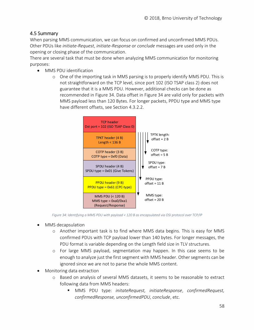
© 2018, Brno University of Technology
58
4.5 Summary When parsing MMS communication, we can focus on confirmed and unconfirmed MMS PDUs. Other PDUs like initiate-Request, initiate-Response or conclude messages are used only in the opening or closing phase of the communication. There are several task that must be done when analyzing MMS communication for monitoring purposes:
MMS PDU identification o One of the importing task in MMS parsing is to properly identify MMS PDU. This is
not straightforward on the TCP level, since port 102 (ISO TSAP class 2) does not guarantee that it is a MMS PDU. However, additional checks can be done as recommended in Figure 34. Data offset in Figure 34 are valid only for packets with MMS payload less than 120 Bytes. For longer packets, PPDU type and MMS type have different offsets, see Section 4.3.2.2.
TPTK length:offset = 2 B
COTP header (3 B)COTP type = 0xf0 (Data)
SPDU header (4 B)SPDU type = 0x01 (Give Tokens)
PPDU header (9 B)PPDU type = 0x61 (CPC-type)
MMS PDU (< 120 B)MMS type = 0xa0/0xa1
(Request/Response)
TPKT header (4 B)Length < 136 B
TCP header Dst port = 102 (ISO TSAP Class 0)
COTP type:offset = 5 B
SPDU type:offset = 7 B
PPDU type:offset = 11 B
MMS type:offset = 20 B
Figure 34: Identifying a MMS PDU with payload < 120 B as encapsulated via OSI protocol over TCP/IP
MMS decapsulation o Another important task is to find where MMS data begins. This is easy for MMS
confirmed PDUs with TCP payload lower than 140 bytes. For longer messages, the
PDU format is variable depending on the Length field size in TLV structures.
o For large MMS payload, segmentation may happen. In this case seems to be
enough to analyze just the first segment with MMS header. Other segments can be
ignored since we are not to parse the whole MMS content.
Monitoring data extraction
o Based on analysis of several MMS datasets, it seems to be reasonable to extract
following data from MMS headers:
MMS PDU type: initateRequest, initiateResponse, confirmedRequest,
confirmedResponse, unconfirmedPDU, conclude, etc.
© 2018, Brno University of Technology
59
For confirmed and unconfirmed services it would be useful to determine
the type of the service, e.g., read, getNameList, informationReport, etc. It
can be also useful to know what variable is requested. However, it can be
tens of variable. For example, dataset mms-kocin1.pcang contains read
requests for 1, 6, or 11 variables depending on the type of the logical device. Similarly to read service, it can be also interesting to see detect write
requests and what datasets or variable are involved. Also, the requests
value to be written can be interesting to know. However, such detailed
parsing would require too much execution time. In addition, there would
be too much monitoring data to be stored. It is not feasible to extract names of datasets or variables from MMS
messages unless it is specifically required. The reason is that a message may contain tens of variable in getNameList, read, write, and other services.
Another approach to security monitoring is to monitor stations (clients) that
are allowed to provide such operations and create a baseline how these
operation are provided in time so that potential attacks on the
communication can be detected.
© 2018, Brno University of Technology
60
References 1. R. E. Mackiewicz, Overview of IEC 61850 and Benefits, 2006 IEEE PES Power Systems
Conference and Exposition, Atlanta, GA, 2006, pp. 623-630. 2. Communication networks and systems for power utility automation – Part 7-4: Basic
communication structure – Compatible logical node classes and data object classes, IEC 61850-7-4, Edition 2.0, 2010, International Electrotechnical Commission.
3. Communication networks and systems for power utility automation – Part 7-2: Basic information and communication structure – Abstract communication service interface (ACSI), IEC 61850-7-2, Edition 2.0, 2010, International Electrotechnical Commission.
4. David Hanes, et al: IoT Fundamentals. Networking Technologies, Protocols, and Use Cases for the Internet of Things, Cisco Press, 2017.
5. Communication networks and systems for power utility automation – Part 7-3: Basic communication structure – Common data classes, IEC 61850-7-3, Edition 2, 2010, International Electrotechnical Commission.
6. Communication networks and systems in substations – Specific Communication Service Mapping (SCSM) – Mappings to MMS (ISO 9506-1 and ISO 9506-2) and to ISO/IEC 8802-3, IEC 61850-8-1, Edition 2.1, 2017, International Electrotechnical Commission.
7. Olivier Dubuisson: ASN.1 Communication Between Heterogeneous Systems, Morgan Kaufmann, 2000. Available at www.oss.com/asn1/resources/books-whitepapers-pubs/dubuisson-asn1-book.PDF [Jan 2018].
8. Nikunj Patel: IEC 61850 Horizontal Goose Communication and Overview, Lambert Academic Publishing, Saarbruecken, Germany, 2011.
9. Industrial automation systems — Manufacturing Message Specification — Part 2: Protocol specification, ISO standard 9506-2:2003, 2nd Edition, 2003, International Organization for Standardization.
10. Marshall T. Rose, Dwight E. Cass: ISO Transport Service on top of the TCP. Version: 3, IETF RFC 1006, 1987.
11. ITU-T: Information technology – Open Systems Interconnection – Protocol for providing the connection-mode transport service, ITU-T X.224, 11/95.
12. ISO Transport Protocol Specification ISO DP 8073, IETF RFC 905, 1984. 13. ITU-T: Information technology – Open Systems Interconnection – Connection-oriented
Session Protocol: Protocol Specification, ITU-T X.225, November, 1995. 14. ITU-T: Information technology – Open Systems Interconnection – Connection-oriented
Protocol for the Association Control Service Element: Protocol Specification, ITU-T X.227, April, 1995.
15. ITU-T: Information technology – Open Systems Interconnection – Connection-oriented Presentation Protocol: Protocol Specification, ITU-T X.226, July, 1994.
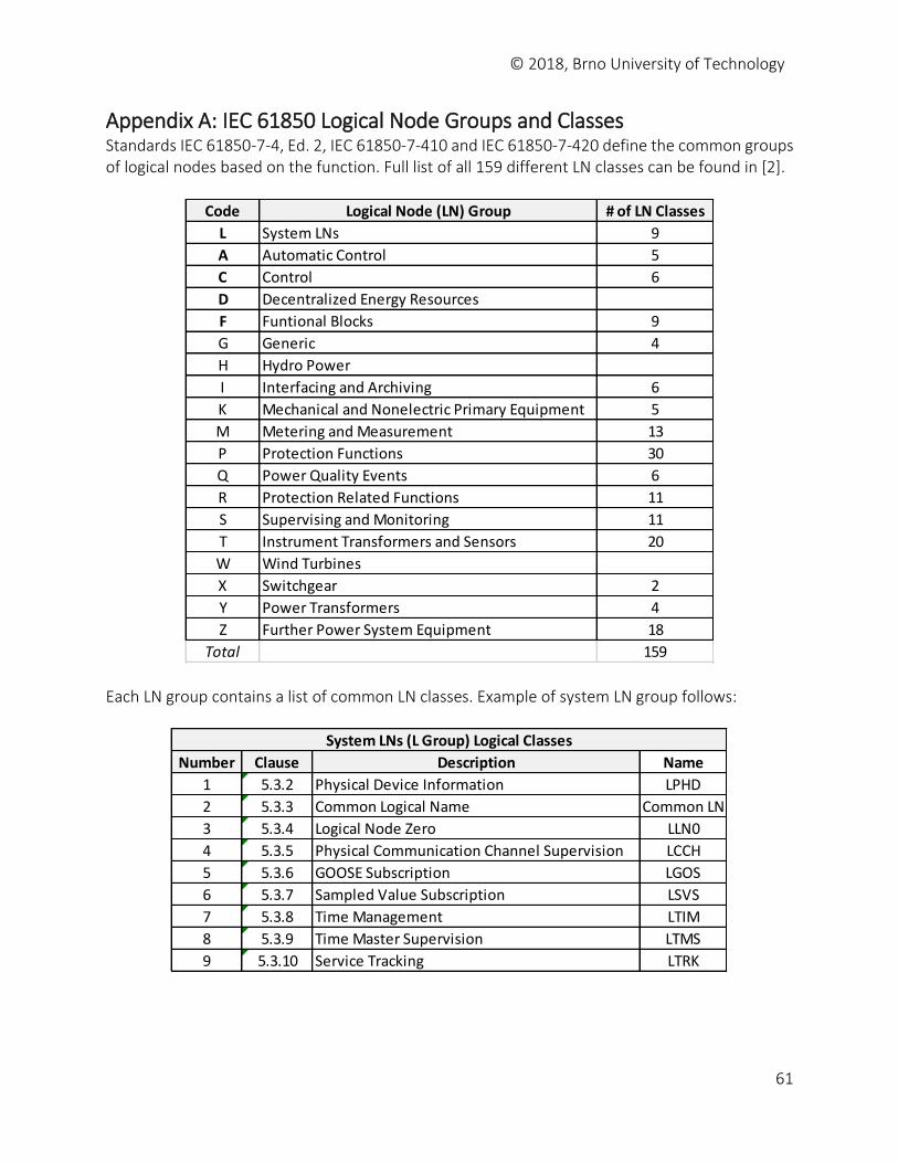
© 2018, Brno University of Technology
61
Appendix A: IEC 61850 Logical Node Groups and Classes Standards IEC 61850-7-4, Ed. 2, IEC 61850-7-410 and IEC 61850-7-420 define the common groups of logical nodes based on the function. Full list of all 159 different LN classes can be found in [2].
Each LN group contains a list of common LN classes. Example of system LN group follows:
Code Logical Node (LN) Group # of LN Classes
L System LNs 9
A Automatic Control 5
C Control 6
D Decentralized Energy Resources
F Funtional Blocks 9
G Generic 4
H Hydro Power
I Interfacing and Archiving 6
K Mechanical and Nonelectric Primary Equipment 5
M Metering and Measurement 13
P Protection Functions 30
Q Power Quality Events 6
R Protection Related Functions 11
S Supervising and Monitoring 11
T Instrument Transformers and Sensors 20
W Wind Turbines
X Switchgear 2
Y Power Transformers 4
Z Further Power System Equipment 18
Total 159
Number Clause Description Name
1 5.3.2 Physical Device Information LPHD
2 5.3.3 Common Logical Name Common LN
3 5.3.4 Logical Node Zero LLN0
4 5.3.5 Physical Communication Channel Supervision LCCH
5 5.3.6 GOOSE Subscription LGOS
6 5.3.7 Sampled Value Subscription LSVS
7 5.3.8 Time Management LTIM
8 5.3.9 Time Master Supervision LTMS
9 5.3.10 Service Tracking LTRK
System LNs (L Group) Logical Classes
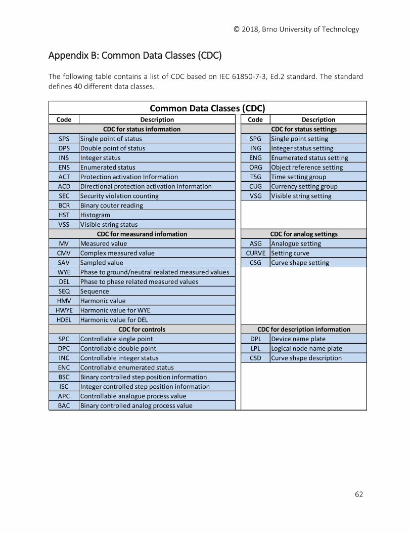
© 2018, Brno University of Technology
62
Appendix B: Common Data Classes (CDC) The following table contains a list of CDC based on IEC 61850-7-3, Ed.2 standard. The standard defines 40 different data classes.
Code Description Code Description
SPS Single point of status SPG Single point setting
DPS Double point of status ING Integer status setting
INS Integer status ENG Enumerated status setting
ENS Enumerated status ORG Object reference setting
ACT Protection activation Information TSG Time setting group
ACD Directional protection activation information CUG Currency setting group
SEC Security violation counting VSG Visible string setting
BCR Binary couter reading
HST Histogram
VSS Visible string status
MV Measured value ASG Analogue setting
CMV Complex measured value CURVE Setting curve
SAV Sampled value CSG Curve shape setting
WYE Phase to ground/neutral realated measured values
DEL Phase to phase related measured values
SEQ Sequence
HMV Harmonic value
HWYE Harmonic value for WYE
HDEL Harmonic value for DEL
SPC Controllable single point DPL Device name plate
DPC Controllable double point LPL Logical node name plate
INC Controllable integer status CSD Curve shape description
ENC Controllable enumerated status
BSC Binary controlled step position information
ISC Integer controlled step position information
APC Controllable analogue process value
BAC Binary controlled analog process value
CDC for measurand infomation
CDC for description information
CDC for status information CDC for status settings
CDC for analog settings
CDC for controls
Common Data Classes (CDC)
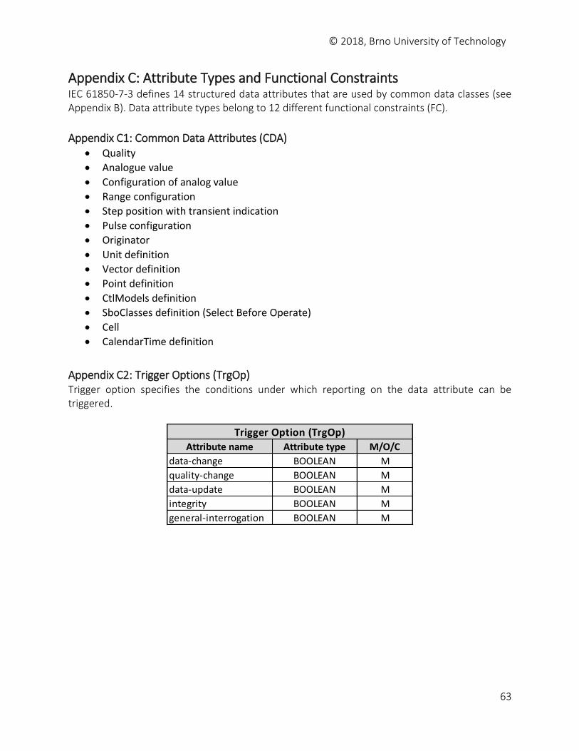
© 2018, Brno University of Technology
63
Appendix C: Attribute Types and Functional Constraints IEC 61850-7-3 defines 14 structured data attributes that are used by common data classes (see Appendix B). Data attribute types belong to 12 different functional constraints (FC).
Appendix C1: Common Data Attributes (CDA) Quality
Analogue value
Configuration of analog value
Range configuration
Step position with transient indication
Pulse configuration
Originator
Unit definition
Vector definition
Point definition
CtlModels definition
SboClasses definition (Select Before Operate)
Cell
CalendarTime definition
Appendix C2: Trigger Options (TrgOp) Trigger option specifies the conditions under which reporting on the data attribute can be triggered.
Attribute name Attribute type M/O/C
data-change BOOLEAN M
quality-change BOOLEAN M
data-update BOOLEAN M
integrity BOOLEAN M
general-interrogation BOOLEAN M
Trigger Option (TrgOp)
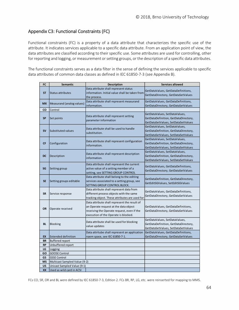
© 2018, Brno University of Technology
64
Appendix C3: Functional Constraints (FC) Functional constraints (FC) is a property of a data attribute that characterizes the specific use of the attribute. It indicates services applicable to a specific data attribute. From an application point of view, the data attributes are classified according to their specific use. Some attributes are used for controlling, other for reporting and logging, or measurement or setting groups, or the description of a specific data attributes. The functional constraints serves as a data filter in the sense of defining the services applicable to specific data attributes of common data classes as defined in IEC 61850-7-3 (see Appendix B).
FCs CO, SR, OR and BL were defined by IEC 61850-7-3, Edition 2. FCs BR, RP, LG, etc. were reinserted for mapping to MMS.
FC Semantic Description Services allowed
ST Status attributes
Data attribute shall represent status
information. Initial value shall be taken from
the process.
GetDataValues, GetDataDefinitions,
GetDataDirectory, GetDataSetValues
MX Measurand (analog values)Data attribute shall represent measurand
information.
GetDataValues, GetDataDefinitions,
GetDataDirectory, GetDataSetValues
CO Control
SP Set pointsData attribute shall represent setting
parameter information
GetDataValues, SetDataValues,
GetDataDefinition, GetDataDirectory,
GetDataSetValues, SetDataSetValues
SV Substituted valuesData attribute shall be used to handle
substitution.
GetDataValues, SetDataValues,
GetDataDefinition, GetDataDirectory,
GetDataSetValues, SetDataSetValues
CF ConfigurationData attribute shall represent configuration
information.
GetDataValues, SetDataValues,
GetDataDefinition, GetDataDirectory,
GetDataSetValues, SetDataSetValues
DC DescriptionData attribute shall represent description
information.
GetDataValues, SetDataValues,
GetDataDefinition, GetDataDirectory,
GetDataSetValues, SetDataSetValues
SG Setting group
Data attribute shall represent the current
active value of a setting member of a
setting, see SETTING GROUP CONTROL
GetDataValues, GetDataDefinitions,
GetDataDirectory, GetDataSetValues
SE Setting groups editable
Data attribute shall belong to the editing
services associated to a setting group, see
SETTING GROUP CONTROL BLOCK.
GetDataDefinition, GetDataDirectory,
GetEditSGValues, SetEditSGValues
SR Service response
Data attribute shall represent data from
different process objects with the same
tracking object. These attributes are used for
GetDataValues, GetDataDefinitions,
GetDataDirectory, GetDataSetValues
OR Operate received
Data attribute shall represent the result of
an Operate request at the data object
receiving the Operate request, even if the
execution of the Operate is blocked.
GetDataValues, GetDataDefinitions,
GetDataDirectory, GetDataSetValues
BL BlockingData attribute shall be used for blocking
value updates
GetDataValues, SetDataValues,
GetDataDefinition, GetDataDirectory,
GetDataSetValues, SetDataSetValues
EX Extended definition
Data attritube shall represent an application
naem space, see IEC 61850-7-1.
GetDataValues, GetDataDefinitions,
GetDataDirectory, GetDataSetValues
BR Buffered report
RP Unbuffered report
LG Logging
GO GOOSE Control
GS GSSE Control
MS Multicast Sampled Value (9-2)
US Unicast Sampled Value (9-1)
XX Used as wild card in ACSI
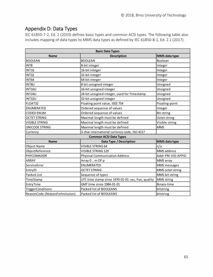
© 2018, Brno University of Technology
65
Appendix D: Data Types IEC 61850-7-2, Ed. 2 (2010) defines basic types and common ACSI types. The following table also includes mapping of data types to MMS data types as defined by IEC 61850-8-1, Ed. 2.1 (2017).
Name Description MMS data type
BOOLEAN BOOLEAN Boolean
INT8 8-bit integer Integer
INT16 16-bit integer Integer
INT32 32-bit integer Integer
INT64 64-bit integer Integer
INT8U 8-bit unsigned integer Unsigned
INT16U 16-bit unsigned integer Unsigned
INT24U 24-bit unsigned integer, used for Timestamp Unsigned
INT32U 32-bit unsigned integer Unsigned
FLOAT32 Floating point value, IEEE 754 Floating-point
ENUMERATED Ordered sequence of values Integer
CODED ENUM Ordered sequence of values Bit-string
OCTET STRING Maximal length must be defined Octet-string
VISIBLE STRING Maximal length must be defined Visible-string
UNICODE STRING Maximal length must be defined MMS
Currency 3-char international currency code, ISO 4217
Name Data Type / Description MMS data type
Object Name VISIBLE STRING 64 n/a
ObjectReference VISIBLE STRING 129 MMS address
PHYCOMADDR Physical Communication Address Addr-PRI-VID-APPID
ARRAY Array 0 .. m OF p MMS array
ServiceError ENUMERATED MMS messages
EntryID OCTET STRING MMS octet string
Packed List Sequence of types MMS bit-string
TimeStamp UTC time stamp since 1970-01-01: sec, frac, quality MMS string
EntryTime GMT time since 1984-01-01 Binary-time
TriggerConditions Packed list of BOOLEANS bitstring
ReasonCode (ReasonForInclusion) Packed list of BOOLEANS bitstring
Basic Data Types
Common ACSI Data Types
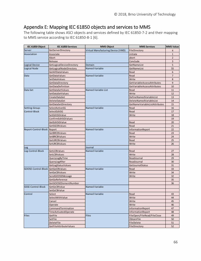
© 2018, Brno University of Technology
66
Appendix E: Mapping IEC 61850 objects and services to MMS The following table shows ASCI objects and services defined by IEC 61850-7-2 and their mapping to MMS service according to IEC 61850-8-1 [6].
IEC 61850 Object IEC 61850 Services MMS Object MMS Services MMS Value
Server GetServerDirectory Virtual Manufacturing Device (VMD) FileDirectory 4
Associate initiate 1
Abort abort 2
Release Conclude 3
Logical Device GetLogicalDeviceDirectory Domain GetNameList 5
GetLogicalNodeDirectory GetNameList 55
GetAllDataValues Read 6
GetDataValues Read 7
SetDataValues Write 8
GetDataDirectory GetVariableAccessAttributes 9
GetDataDefinition GetVariableAccessAttributes 10
GetDataSetValues Read 11
SetDataSetValues Write 12
CreateDataSet DefineNamedVariableList 13
DeleteDataSet DeleteNamedVariableList 14
GetDataSetDirectory GetNameVariableListAttributes 15
SelectActiveSG Read 16
SelectEditSG Read 17
SetEditSGValue Write 18
ConfirmEditSGValues 19
GetEditSGValue Read 20
GetSGCBValues Read 21
Report InformationReport 22
GetBRCBValues Read 23
SetBRCBValues Write 24
GetURCBValues Read 25
SetURCBValues Write 26
Log Journal
GetLCBValues Read 27
SetLCBValues Write 28
QueryLogByTime ReadJournal 29
QueryLogAfter ReadJournal 30
GetLogStatusValues GetJournalStatus 31
GetGoCBValues Read 33
SetGoCBValues Write 34
SendGOOSEMessage Write 32
GetGoReference 35
GetGOOSEElementNumber 36
GetGsCBValue
SetGsCBValue
Select Read 43
SelectWithValue Write 44
Cancel Write 45
Operate Write 46
CommandTermination InformationReport 47
TimeActivatedOperate InformationReport 48
GetFile FileOpen/FileRead/FileClose 49
SetFile ObtainFile 50
DeleteFile FileDelete 51
GetFileAttributeValues FileDirectory 52
Association
GOOSE-Control-Block Named Variable
Named Variable
Named Variable
Logical Node
Data
Data Set
Setting-Group-
Control-Block
Report-Control-Block
Log-Control-Block
Named Variable
Named Variable
Named Variable List
Named Variable
Named Variable
Named Variable
Files
GSSE-Control-Block
Control
Files
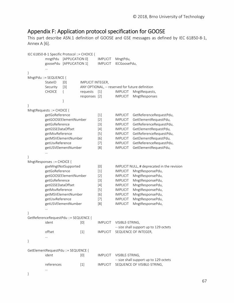
© 2018, Brno University of Technology
67
Appendix F: Application protocol specification for GOOSE This part describe ASN.1 definition of GOOSE and GSE messages as defined by IEC 61850-8-1, Annex A [6]. IEC 61850-8-1 Specific Protocol ::= CHOICE { mngtPdu [APPLICATION 0] IMPLICIT MngtPdu, goosePdu [APPLICATION 1] IMPLICIT IECGoosePdu, … } MngtPdu ::= SEQUENCE { StateID [0] IMPLICIT INTEGER, Security [3] ANY OPTIONAL, -- reserved for future definition CHOICE { requests [1] IMPLICIT MngtRequests, responses [2] IMPLICIT MngtResponses } } MngtRequests ::= CHOICE { getGoReference [1] IMPLICIT GetReferenceRequestPdu, getGOOSEElementNumber [2] IMPLICIT GetElementRequestPdu, getGsReference [3] IMPLICIT GetReferenceRequestPdu, getGSSEDataOffset [4] IMPLICIT GetElementRequestPdu, getMsvReference [5] IMPLICIT GetReferenceRequestPdu, getMSVElementNumber [6] IMPLICIT GetElementRequestPdu, getUsvReference [7] IMPLICIT GetReferenceRequestPdu, getUSVElementNumber [8] IMPLICIT GetElementRequestPdu, … } MngtResponses ::= CHOICE { gseMngtNotSupported [0] IMPLICIT NULL, # deprecated in the revision getGoReference [1] IMPLICIT MngtResponsePdu, getGOOSEElementNumber [2] IMPLICIT MngtResponsePdu, getGsReference [3] IMPLICIT MngtResponsePdu, getGSSEDataOffset [4] IMPLICIT MngtResponsePdu, getMsvReference [5] IMPLICIT MngtResponsePdu, getMSVElementNumber [6] IMPLICIT MngtResponsePdu, getUsvReference [7] IMPLICIT MngtResponsePdu, getUSVElementNumber [8] IMPLICIT MngtResponsePdu, … } GetReferenceRequestPdu ::= SEQUENCE { ident [0] IMPLICIT VISIBLE-STRING, -- size shall support up to 129 octets offset [1] IMPLICIT SEQUENCE OF INTEGER, … } GetElementRequestPdu ::= SEQUENCE { ident [0] IMPLICIT VISIBLE-STRING, -- size shall support up to 129 octets references [1] IMPLICIT SEQUENCE OF VISIBLE-STRING, … }
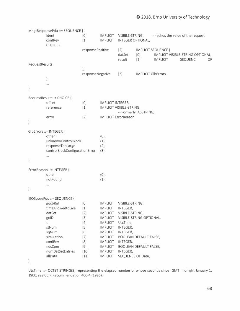
© 2018, Brno University of Technology
68
MngtResponsePdu ::= SEQUENCE { ident [0] IMPLICIT VISIBLE-STRING, - - echos the value of the request confRev [1] IMPLICIT INTEGER OPTIONAL, CHOICE { responsePositive [2] IMPLICIT SEQUENCE { datSet [0] IMPLICIT VISIBLE-STRING OPTIONAL, result [1] IMPLICIT SEQUENC OF RequestResults }, responseNegative [3] IMPLICIT GlbErrors }, … } RequestResults::= CHOICE { offset [0] IMPLICIT INTEGER, reference [1] IMPLICIT VISIBLE-STRING, -- Formerly IA5STRING, error [2] IMPLICIT ErrorReason } GlbErrors ::= INTEGER { other (0), unknownControlBlock (1), responseTooLarge (2), controlBlockConfigurationError (3), … } ErrorReason ::= INTEGER { other (0), notFound (1), … } IECGoosePdu ::= SEQUENCE { gocbRef [0] IMPLICIT VISIBLE-STRING, timeAllowedtoLive [1] IMPLICIT INTEGER, datSet [2] IMPLICIT VISIBLE-STRING, goID [3] IMPLICIT VISIBLE-STRING OPTIONAL, t [4] IMPLICIT UtcTime, stNum [5] IMPLICIT INTEGER, sqNum [6] IMPLICIT INTEGER, simulation [7] IMPLICIT BOOLEAN DEFAULT FALSE, confRev [8] IMPLICIT INTEGER, ndsCom [9] IMPLICIT BOOLEAN DEFAULT FALSE, numDatSetEntries [10] IMPLICIT INTEGER, allData [11] IMPLICIT SEQUENCE OF Data, } UtcTime ::= OCTET STRING(8) representing the elapsed number of whose seconds since GMT midnight January 1, 1900, see CCIR Recommendation 460-4 (1986).
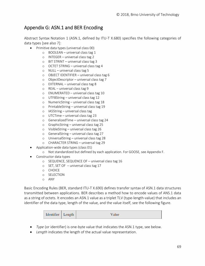
© 2018, Brno University of Technology
69
Appendix G: ASN.1 and BER Encoding Abstract Syntax Notation 1 (ASN.1, defined by ITU-T X.680) specifies the following categories of data types [see also 7]:
Primitive data types (universal class 00) o BOOLEAN – universal class tag 1 o INTEGER – universal class tag 2 o BIT STRINT – universal class tag 3 o OCTET STRING – universal class tag 4 o NULL – universal class tag 5 o OBJECT IDENTIFIER – universal class tag 6 o ObjectDescriptor – universal class tag 7 o EXTERNAL – universal class tag 8 o REAL – universal class tag 9 o ENUMERATED – universal class tag 10 o UTF8String – universal class tag 12 o NumericString – universal class tag 18 o PrintableString – universal class tag 19 o IA5String – universal class tag o UTCTime – universal class tag 23 o GeneralizedTime – universal class tag 24 o GraphicString – universal class tag 25 o VisibleString – universal class tag 26 o GeneralString – universal class tag 27 o UniversalString – universal class tag 28 o CHARACTER STRING – universal tag 29
Application-wide data types (class 01) o Not standardized but defined by each application. For GOOSE, see Appendix F.
Constructor data types o SEQUENCE, SEQUENCE OF – universal class tag 16 o SET, SET OF – universal class tag 17 o CHOICE o SELECTION o ANY
Basic Encoding Rules (BER, standard ITU-T X.690) defines transfer syntax of ASN.1 data structures transmitted between applications. BER describes a method how to encode values of ANS.1 data as a string of octets. It encodes an ASN.1 value as a triplet TLV (type-length-value) that includes an identifier of the data type, length of the value, and the value itself, see the following figure.
Type (or identifier) is one-byte value that indicates the ASN.1 type, see below.
Length indicates the length of the actual value representation.
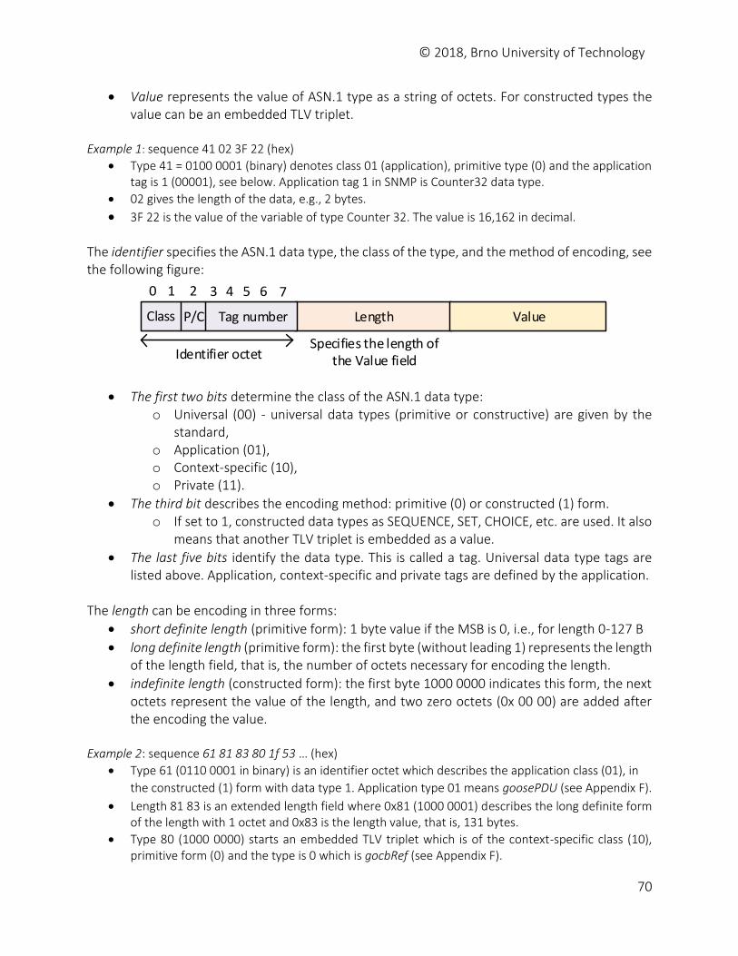
© 2018, Brno University of Technology
70
Value represents the value of ASN.1 type as a string of octets. For constructed types the value can be an embedded TLV triplet.
Example 1: sequence 41 02 3F 22 (hex)
Type 41 = 0100 0001 (binary) denotes class 01 (application), primitive type (0) and the application tag is 1 (00001), see below. Application tag 1 in SNMP is Counter32 data type.
02 gives the length of the data, e.g., 2 bytes.
3F 22 is the value of the variable of type Counter 32. The value is 16,162 in decimal. The identifier specifies the ASN.1 data type, the class of the type, and the method of encoding, see the following figure:
Class P/C Tag number Length Value
Identifier octet
0 1 2 3 4 5 6 7
Specifies the length of the Value field
The first two bits determine the class of the ASN.1 data type: o Universal (00) - universal data types (primitive or constructive) are given by the
standard, o Application (01), o Context-specific (10), o Private (11).
The third bit describes the encoding method: primitive (0) or constructed (1) form. o If set to 1, constructed data types as SEQUENCE, SET, CHOICE, etc. are used. It also
means that another TLV triplet is embedded as a value.
The last five bits identify the data type. This is called a tag. Universal data type tags are listed above. Application, context-specific and private tags are defined by the application.
The length can be encoding in three forms:
short definite length (primitive form): 1 byte value if the MSB is 0, i.e., for length 0-127 B
long definite length (primitive form): the first byte (without leading 1) represents the length of the length field, that is, the number of octets necessary for encoding the length.
indefinite length (constructed form): the first byte 1000 0000 indicates this form, the next octets represent the value of the length, and two zero octets (0x 00 00) are added after the encoding the value.
Example 2: sequence 61 81 83 80 1f 53 … (hex)
Type 61 (0110 0001 in binary) is an identifier octet which describes the application class (01), in
the constructed (1) form with data type 1. Application type 01 means goosePDU (see Appendix F).
Length 81 83 is an extended length field where 0x81 (1000 0001) describes the long definite form of the length with 1 octet and 0x83 is the length value, that is, 131 bytes.
Type 80 (1000 0000) starts an embedded TLV triplet which is of the context-specific class (10), primitive form (0) and the type is 0 which is gocbRef (see Appendix F).
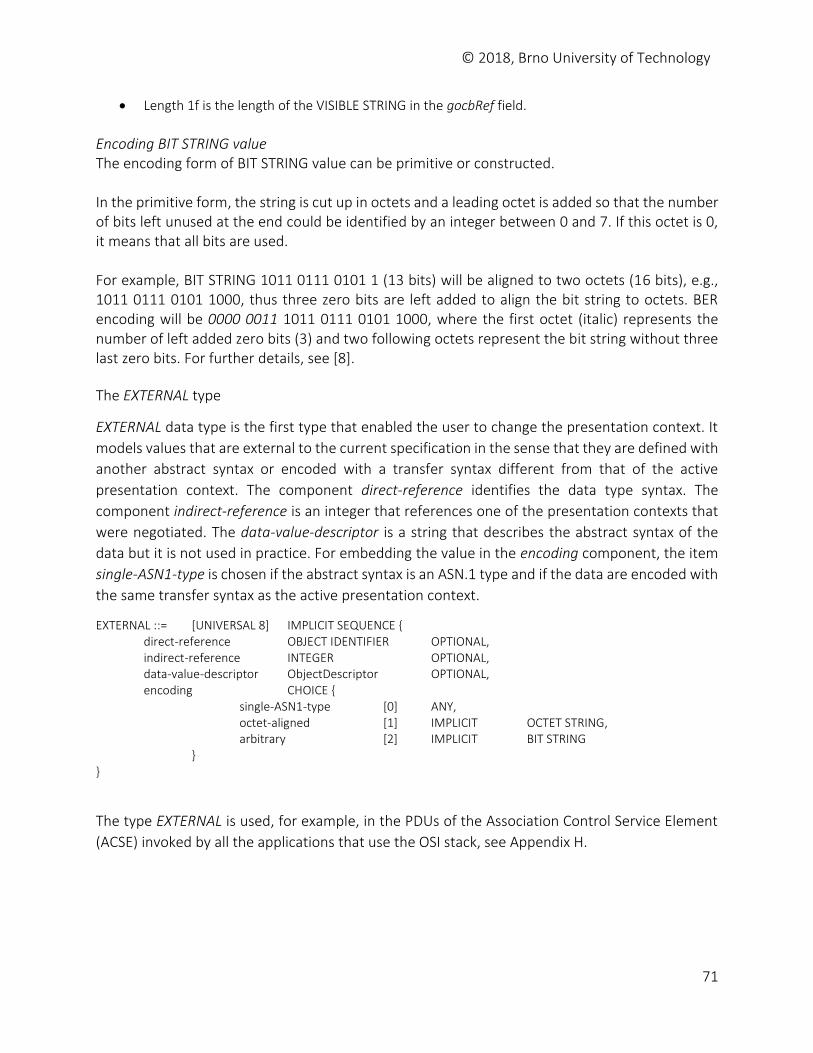
© 2018, Brno University of Technology
71
Length 1f is the length of the VISIBLE STRING in the gocbRef field.
Encoding BIT STRING value The encoding form of BIT STRING value can be primitive or constructed. In the primitive form, the string is cut up in octets and a leading octet is added so that the number of bits left unused at the end could be identified by an integer between 0 and 7. If this octet is 0, it means that all bits are used. For example, BIT STRING 1011 0111 0101 1 (13 bits) will be aligned to two octets (16 bits), e.g., 1011 0111 0101 1000, thus three zero bits are left added to align the bit string to octets. BER encoding will be 0000 0011 1011 0111 0101 1000, where the first octet (italic) represents the number of left added zero bits (3) and two following octets represent the bit string without three last zero bits. For further details, see [8].
The EXTERNAL type
EXTERNAL data type is the first type that enabled the user to change the presentation context. It
models values that are external to the current specification in the sense that they are defined with
another abstract syntax or encoded with a transfer syntax different from that of the active
presentation context. The component direct-reference identifies the data type syntax. The
component indirect-reference is an integer that references one of the presentation contexts that
were negotiated. The data-value-descriptor is a string that describes the abstract syntax of the
data but it is not used in practice. For embedding the value in the encoding component, the item
single-ASN1-type is chosen if the abstract syntax is an ASN.1 type and if the data are encoded with
the same transfer syntax as the active presentation context.
EXTERNAL ::= [UNIVERSAL 8] IMPLICIT SEQUENCE { direct-reference OBJECT IDENTIFIER OPTIONAL, indirect-reference INTEGER OPTIONAL, data-value-descriptor ObjectDescriptor OPTIONAL, encoding CHOICE { single-ASN1-type [0] ANY, octet-aligned [1] IMPLICIT OCTET STRING, arbitrary [2] IMPLICIT BIT STRING } }
The type EXTERNAL is used, for example, in the PDUs of the Association Control Service Element
(ACSE) invoked by all the applications that use the OSI stack, see Appendix H.
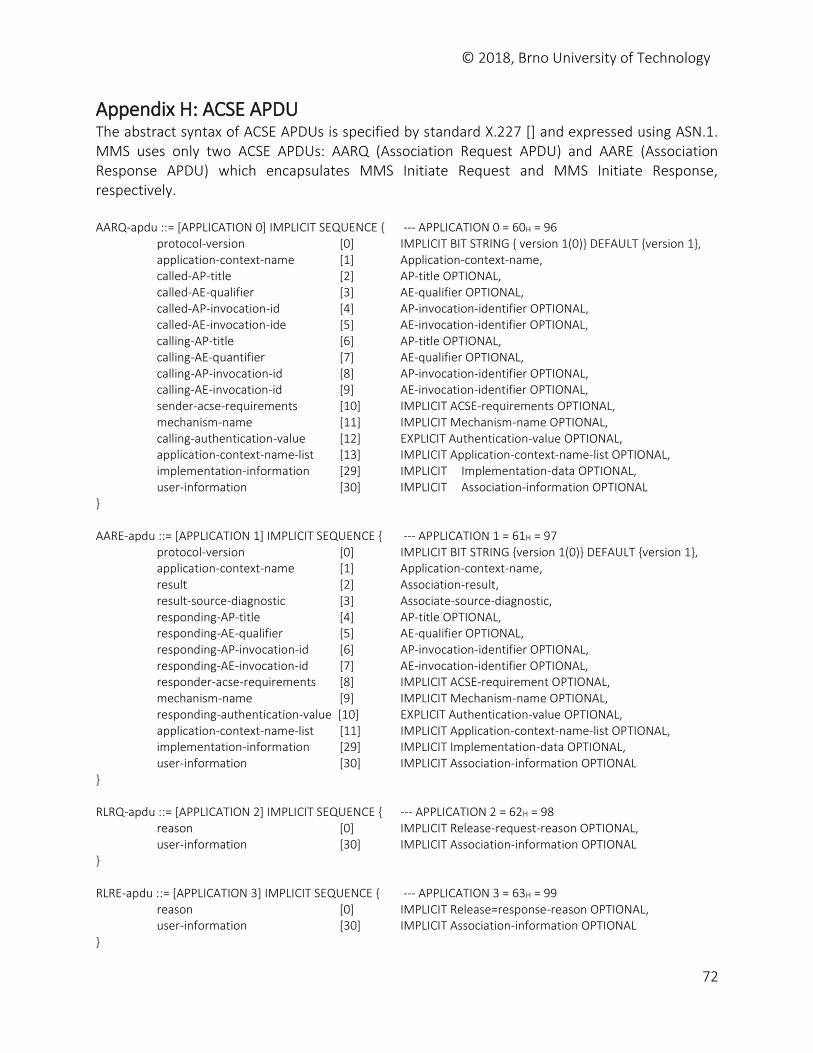
© 2018, Brno University of Technology
72
Appendix H: ACSE APDU The abstract syntax of ACSE APDUs is specified by standard X.227 [] and expressed using ASN.1. MMS uses only two ACSE APDUs: AARQ (Association Request APDU) and AARE (Association Response APDU) which encapsulates MMS Initiate Request and MMS Initiate Response, respectively. AARQ-apdu ::= [APPLICATION 0] IMPLICIT SEQUENCE { --- APPLICATION 0 = 60H = 96 protocol-version [0] IMPLICIT BIT STRING { version 1(0)} DEFAULT {version 1}, application-context-name [1] Application-context-name, called-AP-title [2] AP-title OPTIONAL, called-AE-qualifier [3] AE-qualifier OPTIONAL, called-AP-invocation-id [4] AP-invocation-identifier OPTIONAL, called-AE-invocation-ide [5] AE-invocation-identifier OPTIONAL, calling-AP-title [6] AP-title OPTIONAL, calling-AE-quantifier [7] AE-qualifier OPTIONAL, calling-AP-invocation-id [8] AP-invocation-identifier OPTIONAL, calling-AE-invocation-id [9] AE-invocation-identifier OPTIONAL, sender-acse-requirements [10] IMPLICIT ACSE-requirements OPTIONAL, mechanism-name [11] IMPLICIT Mechanism-name OPTIONAL, calling-authentication-value [12] EXPLICIT Authentication-value OPTIONAL, application-context-name-list [13] IMPLICIT Application-context-name-list OPTIONAL, implementation-information [29] IMPLICIT Implementation-data OPTIONAL, user-information [30] IMPLICIT Association-information OPTIONAL } AARE-apdu ::= [APPLICATION 1] IMPLICIT SEQUENCE { --- APPLICATION 1 = 61H = 97 protocol-version [0] IMPLICIT BIT STRING {version 1(0)} DEFAULT {version 1}, application-context-name [1] Application-context-name, result [2] Association-result, result-source-diagnostic [3] Associate-source-diagnostic, responding-AP-title [4] AP-title OPTIONAL, responding-AE-qualifier [5] AE-qualifier OPTIONAL, responding-AP-invocation-id [6] AP-invocation-identifier OPTIONAL, responding-AE-invocation-id [7] AE-invocation-identifier OPTIONAL, responder-acse-requirements [8] IMPLICIT ACSE-requirement OPTIONAL, mechanism-name [9] IMPLICIT Mechanism-name OPTIONAL, responding-authentication-value [10] EXPLICIT Authentication-value OPTIONAL, application-context-name-list [11] IMPLICIT Application-context-name-list OPTIONAL, implementation-information [29] IMPLICIT Implementation-data OPTIONAL, user-information [30] IMPLICIT Association-information OPTIONAL } RLRQ-apdu ::= [APPLICATION 2] IMPLICIT SEQUENCE { --- APPLICATION 2 = 62H = 98 reason [0] IMPLICIT Release-request-reason OPTIONAL, user-information [30] IMPLICIT Association-information OPTIONAL } RLRE-apdu ::= [APPLICATION 3] IMPLICIT SEQUENCE { --- APPLICATION 3 = 63H = 99 reason [0] IMPLICIT Release=response-reason OPTIONAL, user-information [30] IMPLICIT Association-information OPTIONAL }
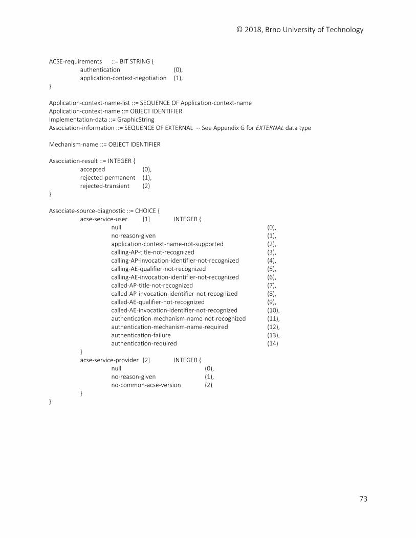
© 2018, Brno University of Technology
73
ACSE-requirements ::= BIT STRING { authentication (0), application-context-negotiation (1), } Application-context-name-list ::= SEQUENCE OF Application-context-name Application-context-name ::= OBJECT IDENTIFIER Implementation-data ::= GraphicString Association-information ::= SEQUENCE OF EXTERNAL -- See Appendix G for EXTERNAL data type Mechanism-name ::= OBJECT IDENTIFIER Association-result ::= INTEGER { accepted (0), rejected-permanent (1), rejected-transient (2) } Associate-source-diagnostic ::= CHOICE { acse-service-user [1] INTEGER { null (0), no-reason-given (1), application-context-name-not-supported (2), calling-AP-title-not-recognized (3), calling-AP-invocation-identifier-not-recognized (4), calling-AE-qualifier-not-recognized (5), calling-AE-invocation-identifier-not-recognized (6), called-AP-title-not-recognized (7), called-AP-invocation-identifier-not-recognized (8), called-AE-qualifier-not-recognized (9), called-AE-invocation-identifier-not-recognized (10), authentication-mechanism-name-not-recognized (11), authentication-mechanism-name-required (12), authentication-failure (13), authentication-required (14) } acse-service-provider [2] INTEGER { null (0), no-reason-given (1), no-common-acse-version (2) } }
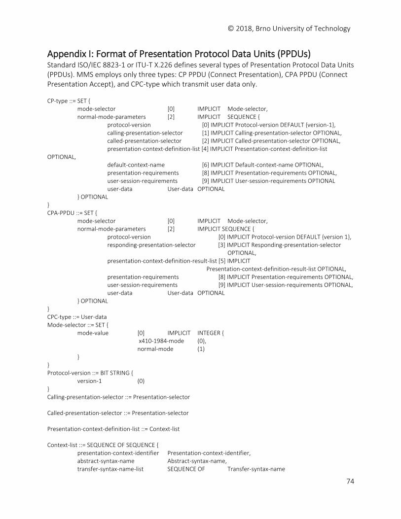
© 2018, Brno University of Technology
74
Appendix I: Format of Presentation Protocol Data Units (PPDUs) Standard ISO/IEC 8823-1 or ITU-T X.226 defines several types of Presentation Protocol Data Units (PPDUs). MMS employs only three types: CP PPDU (Connect Presentation), CPA PPDU (Connect Presentation Accept), and CPC-type which transmit user data only. CP-type ::= SET { mode-selector [0] IMPLICIT Mode-selector, normal-mode-parameters [2] IMPLICIT SEQUENCE { protocol-version [0] IMPLICIT Protocol-version DEFAULT {version-1}, calling-presentation-selector [1] IMPLICIT Calling-presentation-selector OPTIONAL, called-presentation-selector [2] IMPLICIT Called-presentation-selector OPTIONAL, presentation-context-definition-list [4] IMPLICIT Presentation-context-definition-list OPTIONAL, default-context-name [6] IMPLICIT Default-context-name OPTIONAL, presentation-requirements [8] IMPLICIT Presentation-requirements OPTIONAL, user-session-requirements [9] IMPLICIT User-session-requirements OPTIONAL user-data User-data OPTIONAL } OPTIONAL } CPA-PPDU ::= SET { mode-selector [0] IMPLICIT Mode-selector, normal-mode-parameters [2] IMPLICIT SEQUENCE { protocol-version [0] IMPLICIT Protocol-version DEFAULT {version 1}, responding-presentation-selector [3] IMPLICIT Responding-presentation-selector OPTIONAL, presentation-context-definition-result-list [5] IMPLICIT Presentation-context-definition-result-list OPTIONAL, presentation-requirements [8] IMPLICIT Presentation-requirements OPTIONAL, user-session-requirements [9] IMPLICIT User-session-requirements OPTIONAL, user-data User-data OPTIONAL } OPTIONAL } CPC-type ::= User-data Mode-selector ::= SET { mode-value [0] IMPLICIT INTEGER { x410-1984-mode (0), normal-mode (1) } } Protocol-version ::= BIT STRING { version-1 (0) } Calling-presentation-selector ::= Presentation-selector Called-presentation-selector ::= Presentation-selector Presentation-context-definition-list ::= Context-list Context-list ::= SEQUENCE OF SEQUENCE { presentation-context-identifier Presentation-context-identifier, abstract-syntax-name Abstract-syntax-name, transfer-syntax-name-list SEQUENCE OF Transfer-syntax-name
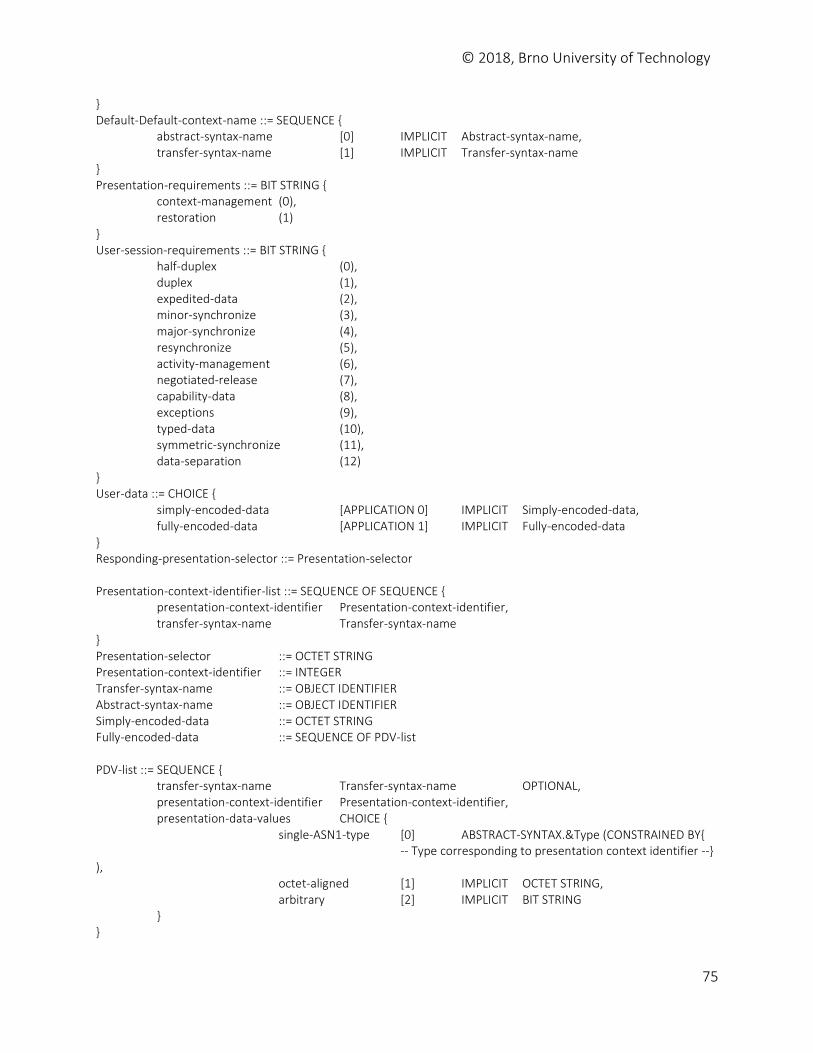
© 2018, Brno University of Technology
75
} Default-Default-context-name ::= SEQUENCE { abstract-syntax-name [0] IMPLICIT Abstract-syntax-name, transfer-syntax-name [1] IMPLICIT Transfer-syntax-name } Presentation-requirements ::= BIT STRING { context-management (0), restoration (1) } User-session-requirements ::= BIT STRING { half-duplex (0), duplex (1), expedited-data (2), minor-synchronize (3), major-synchronize (4), resynchronize (5), activity-management (6), negotiated-release (7), capability-data (8), exceptions (9), typed-data (10), symmetric-synchronize (11), data-separation (12) } User-data ::= CHOICE { simply-encoded-data [APPLICATION 0] IMPLICIT Simply-encoded-data, fully-encoded-data [APPLICATION 1] IMPLICIT Fully-encoded-data } Responding-presentation-selector ::= Presentation-selector Presentation-context-identifier-list ::= SEQUENCE OF SEQUENCE { presentation-context-identifier Presentation-context-identifier, transfer-syntax-name Transfer-syntax-name } Presentation-selector ::= OCTET STRING Presentation-context-identifier ::= INTEGER Transfer-syntax-name ::= OBJECT IDENTIFIER Abstract-syntax-name ::= OBJECT IDENTIFIER Simply-encoded-data ::= OCTET STRING Fully-encoded-data ::= SEQUENCE OF PDV-list PDV-list ::= SEQUENCE { transfer-syntax-name Transfer-syntax-name OPTIONAL, presentation-context-identifier Presentation-context-identifier, presentation-data-values CHOICE { single-ASN1-type [0] ABSTRACT-SYNTAX.&Type (CONSTRAINED BY{ -- Type corresponding to presentation context identifier --} ), octet-aligned [1] IMPLICIT OCTET STRING, arbitrary [2] IMPLICIT BIT STRING } }
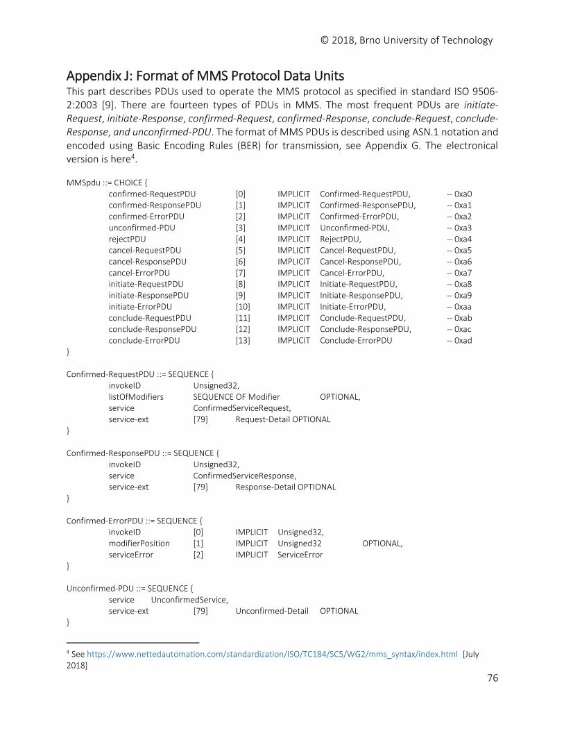
© 2018, Brno University of Technology
76
Appendix J: Format of MMS Protocol Data Units This part describes PDUs used to operate the MMS protocol as specified in standard ISO 9506-2:2003 [9]. There are fourteen types of PDUs in MMS. The most frequent PDUs are initiate-Request, initiate-Response, confirmed-Request, confirmed-Response, conclude-Request, conclude-Response, and unconfirmed-PDU. The format of MMS PDUs is described using ASN.1 notation and encoded using Basic Encoding Rules (BER) for transmission, see Appendix G. The electronical version is here4. MMSpdu ::= CHOICE { confirmed-RequestPDU [0] IMPLICIT Confirmed-RequestPDU, -- 0xa0 confirmed-ResponsePDU [1] IMPLICIT Confirmed-ResponsePDU, -- 0xa1 confirmed-ErrorPDU [2] IMPLICIT Confirmed-ErrorPDU, -- 0xa2 unconfirmed-PDU [3] IMPLICIT Unconfirmed-PDU, -- 0xa3 rejectPDU [4] IMPLICIT RejectPDU, -- 0xa4 cancel-RequestPDU [5] IMPLICIT Cancel-RequestPDU, -- 0xa5 cancel-ResponsePDU [6] IMPLICIT Cancel-ResponsePDU, -- 0xa6 cancel-ErrorPDU [7] IMPLICIT Cancel-ErrorPDU, -- 0xa7 initiate-RequestPDU [8] IMPLICIT Initiate-RequestPDU, -- 0xa8 initiate-ResponsePDU [9] IMPLICIT Initiate-ResponsePDU, -- 0xa9 initiate-ErrorPDU [10] IMPLICIT Initiate-ErrorPDU, -- 0xaa conclude-RequestPDU [11] IMPLICIT Conclude-RequestPDU, -- 0xab conclude-ResponsePDU [12] IMPLICIT Conclude-ResponsePDU, -- 0xac conclude-ErrorPDU [13] IMPLICIT Conclude-ErrorPDU -- 0xad } Confirmed-RequestPDU ::= SEQUENCE { invokeID Unsigned32, listOfModifiers SEQUENCE OF Modifier OPTIONAL, service ConfirmedServiceRequest, service-ext [79] Request-Detail OPTIONAL } Confirmed-ResponsePDU ::= SEQUENCE { invokeID Unsigned32, service ConfirmedServiceResponse, service-ext [79] Response-Detail OPTIONAL } Confirmed-ErrorPDU ::= SEQUENCE { invokeID [0] IMPLICIT Unsigned32, modifierPosition [1] IMPLICIT Unsigned32 OPTIONAL, serviceError [2] IMPLICIT ServiceError } Unconfirmed-PDU ::= SEQUENCE { service UnconfirmedService, service-ext [79] Unconfirmed-Detail OPTIONAL }
4 See https://www.nettedautomation.com/standardization/ISO/TC184/SC5/WG2/mms_syntax/index.html [July 2018]
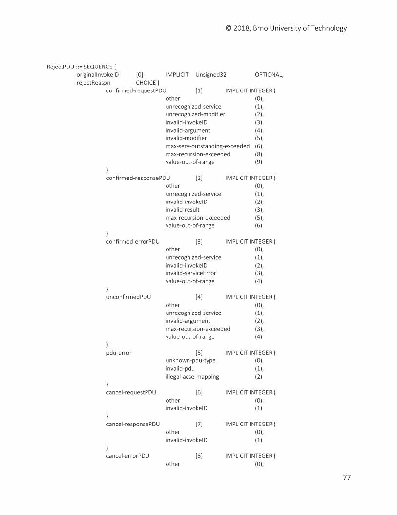
© 2018, Brno University of Technology
77
RejectPDU ::= SEQUENCE { originalInvokeID [0] IMPLICIT Unsigned32 OPTIONAL, rejectReason CHOICE { confirmed-requestPDU [1] IMPLICIT INTEGER { other (0), unrecognized-service (1), unrecognized-modifier (2), invalid-invokeID (3), invalid-argument (4), invalid-modifier (5), max-serv-outstanding-exceeded (6), max-recursion-exceeded (8), value-out-of-range (9) } confirmed-responsePDU [2] IMPLICIT INTEGER { other (0), unrecognized-service (1), invalid-invokeID (2), invalid-result (3), max-recursion-exceeded (5), value-out-of-range (6) } confirmed-errorPDU [3] IMPLICIT INTEGER { other (0), unrecognized-service (1), invalid-invokeID (2), invalid-serviceError (3), value-out-of-range (4) } unconfirmedPDU [4] IMPLICIT INTEGER { other (0), unrecognized-service (1), invalid-argument (2), max-recursion-exceeded (3), value-out-of-range (4) } pdu-error [5] IMPLICIT INTEGER { unknown-pdu-type (0), invalid-pdu (1), illegal-acse-mapping (2) } cancel-requestPDU [6] IMPLICIT INTEGER { other (0), invalid-invokeID (1) } cancel-responsePDU [7] IMPLICIT INTEGER { other (0), invalid-invokeID (1) } cancel-errorPDU [8] IMPLICIT INTEGER { other (0),
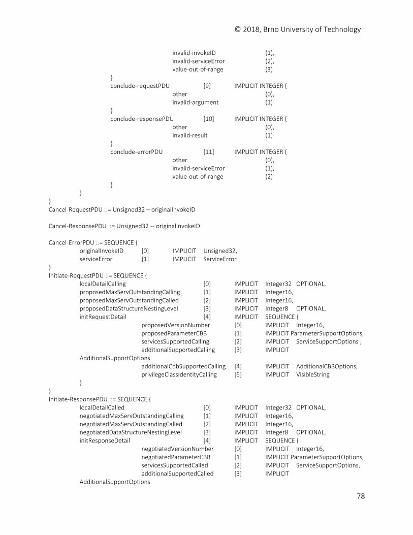
© 2018, Brno University of Technology
78
invalid-invokeID (1), invalid-serviceError (2), value-out-of-range (3) } conclude-requestPDU [9] IMPLICIT INTEGER { other (0), invalid-argument (1) } conclude-responsePDU [10] IMPLICIT INTEGER { other (0), invalid-result (1) } conclude-errorPDU [11] IMPLICIT INTEGER { other (0), invalid-serviceError (1), value-out-of-range (2) } } } Cancel-RequestPDU ::= Unsigned32 – originalInvokeID Cancel-ResponsePDU ::= Unsigned32 -- originalInvokeID Cancel-ErrorPDU ::= SEQUENCE { originalInvokeID [0] IMPLICIT Unsigned32, serviceError [1] IMPLICIT ServiceError } Initiate-RequestPDU ::= SEQUENCE { localDetailCalling [0] IMPLICIT Integer32 OPTIONAL, proposedMaxServOutstandingCalling [1] IMPLICIT Integer16, proposedMaxServOutstandingCalled [2] IMPLICIT Integer16, proposedDataStructureNestingLevel [3] IMPLICIT Integer8 OPTIONAL, initRequestDetail [4] IMPLICIT SEQUENCE { proposedVersionNumber [0] IMPLICIT Integer16, proposedParameterCBB [1] IMPLICIT ParameterSupportOptions, servicesSupportedCalling [2] IMPLICIT ServiceSupportOptions , additionalSupportedCalling [3] IMPLICIT AdditionalSupportOptions additionalCbbSupportedCalling [4] IMPLICIT AdditionalCBBOptions, privilegeClassIdentityCalling [5] IMPLICIT VisibleString } } Initiate-ResponsePDU ::= SEQUENCE { localDetailCalled [0] IMPLICIT Integer32 OPTIONAL, negotiatedMaxServOutstandingCalling [1] IMPLICIT Integer16, negotiatedMaxServOutstandingCalled [2] IMPLICIT Integer16, negotiatedDataStructureNestingLevel [3] IMPLICIT Integer8 OPTIONAL, initResponseDetail [4] IMPLICIT SEQUENCE { negotiatedVersionNumber [0] IMPLICIT Integer16, negotiatedParameterCBB [1] IMPLICIT ParameterSupportOptions, servicesSupportedCalled [2] IMPLICIT ServiceSupportOptions, additionalSupportedCalled [3] IMPLICIT AdditionalSupportOptions
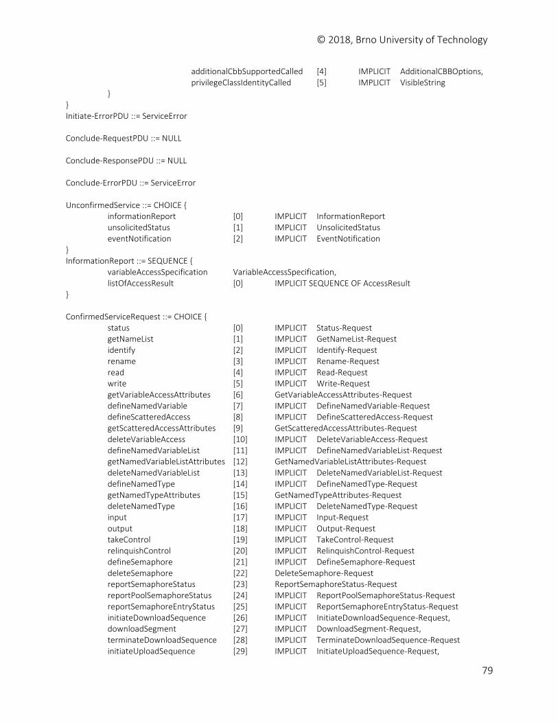
© 2018, Brno University of Technology
79
additionalCbbSupportedCalled [4] IMPLICIT AdditionalCBBOptions, privilegeClassIdentityCalled [5] IMPLICIT VisibleString } } Initiate-ErrorPDU ::= ServiceError Conclude-RequestPDU ::= NULL Conclude-ResponsePDU ::= NULL Conclude-ErrorPDU ::= ServiceError UnconfirmedService ::= CHOICE { informationReport [0] IMPLICIT InformationReport unsolicitedStatus [1] IMPLICIT UnsolicitedStatus eventNotification [2] IMPLICIT EventNotification } InformationReport ::= SEQUENCE { variableAccessSpecification VariableAccessSpecification, listOfAccessResult [0] IMPLICIT SEQUENCE OF AccessResult } ConfirmedServiceRequest ::= CHOICE { status [0] IMPLICIT Status-Request getNameList [1] IMPLICIT GetNameList-Request identify [2] IMPLICIT Identify-Request rename [3] IMPLICIT Rename-Request read [4] IMPLICIT Read-Request write [5] IMPLICIT Write-Request getVariableAccessAttributes [6] GetVariableAccessAttributes-Request defineNamedVariable [7] IMPLICIT DefineNamedVariable-Request defineScatteredAccess [8] IMPLICIT DefineScatteredAccess-Request getScatteredAccessAttributes [9] GetScatteredAccessAttributes-Request deleteVariableAccess [10] IMPLICIT DeleteVariableAccess-Request defineNamedVariableList [11] IMPLICIT DefineNamedVariableList-Request getNamedVariableListAttributes [12] GetNamedVariableListAttributes-Request deleteNamedVariableList [13] IMPLICIT DeleteNamedVariableList-Request defineNamedType [14] IMPLICIT DefineNamedType-Request getNamedTypeAttributes [15] GetNamedTypeAttributes-Request deleteNamedType [16] IMPLICIT DeleteNamedType-Request input [17] IMPLICIT Input-Request output [18] IMPLICIT Output-Request takeControl [19] IMPLICIT TakeControl-Request relinquishControl [20] IMPLICIT RelinquishControl-Request defineSemaphore [21] IMPLICIT DefineSemaphore-Request deleteSemaphore [22] DeleteSemaphore-Request reportSemaphoreStatus [23] ReportSemaphoreStatus-Request reportPoolSemaphoreStatus [24] IMPLICIT ReportPoolSemaphoreStatus-Request reportSemaphoreEntryStatus [25] IMPLICIT ReportSemaphoreEntryStatus-Request initiateDownloadSequence [26] IMPLICIT InitiateDownloadSequence-Request, downloadSegment [27] IMPLICIT DownloadSegment-Request, terminateDownloadSequence [28] IMPLICIT TerminateDownloadSequence-Request initiateUploadSequence [29] IMPLICIT InitiateUploadSequence-Request,

© 2018, Brno University of Technology
80
uploadSegment [30] IMPLICIT UploadSegment-Request, terminateUploadSequence [31] IMPLICIT TerminateUploadSequence-Request requestDomainDownload [32] IMPLICIT RequestDomainDownload-Request requestDomainUpload [33] IMPLICIT RequestDomainUpload-Request loadDomainContent [34] IMPLICIT LoadDomainContent-Request storeDomainContent [35] IMPLICIT StoreDomainContent-Request deleteDomain [36] IMPLICIT DeleteDomain-Request getDomainAttributes [37] IMPLICIT GetDomainAttributes-Request createProgramInvocation [38] IMPLICIT CreateProgramInvocation-Request deleteProgramInvocation [39] IMPLICIT DeleteProgramInvocation-Request start [40] IMPLICIT Start-Request stop [41] IMPLICIT Stop-Request resume [42] IMPLICIT Resume-Request reset [43] IMPLICIT Reset-Request kill [44] IMPLICIT Kill-Request getProgramInvocationAttributes [45] IMPLICIT GetProgramInvocationAttributes-Request obtainFile [46] IMPLICIT ObtainFile-Request defineEventCondition [47] IMPLICIT DefineEventCondition-Request deleteEventCondition [48] DeleteEventCondition-Request getEventConditionAttributes [49] GetEventConditionAttributes-Request reportEventConditionStatus [50] ReportEventConditionStatus-Request alterEventConditionMonitoring [51] IMPLICIT AlterEventConditionMonitoring-Request triggerEvent [52] IMPLICIT TriggerEvent-Request defineEventAction [53] IMPLICIT DefineEventAction-Request deleteEventAction [54] DeleteEventAction-Request getEventActionAttributes [55] GetEventActionAttributes-Request reportEventActionStatus [56] ReportEventActionStatus-Request defineEventEnrollment [57] IMPLICIT DefineEventEnrollment-Request deleteEventEnrollment [58] DeleteEventEnrollment-Request alterEventEnrollment [59] IMPLICIT AlterEventEnrollment-Request reportEventEnrollmentStatus [60] ReportEventEnrollmentStatus-Request getEventEnrollmentAttributes [61] IMPLICIT GetEventEnrollmentAttributes-Request acknowledgeEventNotification [62] IMPLICIT AcknowledgeEventNotification-Request getAlarmSummary [63] IMPLICIT GetAlarmSummary-Request getAlarmEnrollmentSummary [64] IMPLICIT GetAlarmEnrollmentSummary-Request readJournal [65] IMPLICIT ReadJournal-Request writeJournal [66] IMPLICIT WriteJournal-Request initializeJournal [67] IMPLICIT InitializeJournal-Request reportJournalStatus [68] ReportJournalStatus-Request createJournal [69] IMPLICIT CreateJournal-Request deleteJournal [70] IMPLICIT DeleteJournal-Request getCapabilityList [71] IMPLICIT GetCapabilityList-Request fileOpen [72] IMPLICIT FileOpen-Request fileRead [73] IMPLICIT FileRead-Request fileClose [74] IMPLICIT FileClose-Request fileRename [75] IMPLICIT FileRename-Request fileDelete [76] IMPLICIT FileDelete-Request fileDirectory [77] IMPLICIT FileDirectory-Request additionalService [78] AdditionalService-Request getDataExchangeAttributes [80] GetDataExchangeAttributes-Request exchangeData [81] IMPLICIT ExchangeData-Request defineAccessControlList [82] IMPLICIT DefineAccessControlList-Request getAccessControlListAttributes [83] GetAccessControlListAttributes-Request

© 2018, Brno University of Technology
81
reportAccessControlledObjects [84] IMPLICIT ReportAccessControlledObjects-Request deleteAccessControlList [85] IMPLICIT DeleteAccessControlList-Request changeAccessControl [86] IMPLICIT ChangeAccessControl-Request } ConfirmedServiceResponse ::= CHOICE { status [0] IMPLICIT Status-Response, getNameList [1] IMPLICIT GetNameList-Response, identify [2] IMPLICIT Identify-Response, rename [3] IMPLICIT Rename-Response, read [4] IMPLICIT Read-Response, write [5] IMPLICIT Write-Response, getVariableAccessAttributes [6] IMPLICIT GetVariableAccessAttributes-Response, defineNamedVariable [7] IMPLICIT DefineNamedVariable-Response defineScatteredAccess [8] IMPLICIT DefineScatteredAccess-Response, getScatteredAccessAttributes [9] IMPLICIT GetScatteredAccessAttributes-Response, deleteVariableAccess [10] IMPLICIT DeleteVariableAccess-Response, defineNamedVariableList [11] IMPLICIT DefineNamedVariableList-Response, getNamedVariableListAttributes [12] IMPLICIT GetNamedVariableListAttributes-Response, deleteNamedVariableList [13] IMPLICIT DeleteNamedVariableList-Response, defineNamedType [14] IMPLICIT DefineNamedType-Response, getNamedTypeAttributes [15] IMPLICIT GetNamedTypeAttributes-Response, deleteNamedType [16] IMPLICIT DeleteNamedType-Response, input [17] IMPLICIT Input-Response, output [18] IMPLICIT Output-Response, takeControl [19] TakeControl-Response, relinquishControl [20] IMPLICIT RelinquishControl-Response, defineSemaphore [21] IMPLICIT DefineSemaphore-Response, deleteSemaphore [22] IMPLICIT DeleteSemaphore-Response, reportSemaphoreStatus [23] IMPLICIT ReportSemaphoreStatus-Response, reportPoolSemaphoreStatus [24] IMPLICIT ReportPoolSemaphoreStatus-Response, reportSemaphoreEntryStatus [25] IMPLICIT ReportSemaphoreEntryStatus-Response, initiateDownloadSequence [26] IMPLICIT InitiateDownloadSequence-Response, downloadSegment [27] IMPLICIT DownloadSegment-Response, terminateDownloadSequence [28] IMPLICIT TerminateDownloadSequence-Response, initiateUploadSequence [29] IMPLICIT InitiateUploadSequence-Response, uploadSegment [30] IMPLICIT UploadSegment-Response, terminateUploadSequence [31] IMPLICIT TerminateUploadSequence-Response, requestDomainDownload [32] IMPLICIT RequestDomainDownload-Response, requestDomainUpload [33] IMPLICIT RequestDomainUpload-Response, loadDomainContent [34] IMPLICIT LoadDomainContent-Response, storeDomainContent [35] IMPLICIT StoreDomainContent-Response, deleteDomain [36] IMPLICIT DeleteDomain-Response, getDomainAttributes [37] IMPLICIT GetDomainAttributes-Response, createProgramInvocation [38] IMPLICIT CreateProgramInvocation-Response, deleteProgramInvocation [39] IMPLICIT DeleteProgramInvocation-Response, start [40] IMPLICIT Start-Response, stop [41] IMPLICIT Stop-Response, resume [42] IMPLICIT Resume-Response, reset [43] IMPLICIT Reset-Response, kill [44] IMPLICIT Kill-Response, getProgramInvocationAttributes [45] IMPLICIT GetProgramInvocationAttributes-Response, obtainFile [46] IMPLICIT ObtainFile-Response, defineEventCondition [47] IMPLICIT DefineEventCondition-Response,
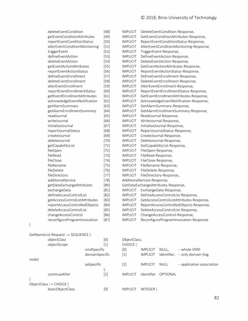
© 2018, Brno University of Technology
82
deleteEventCondition [48] IMPLICIT DeleteEventCondition-Response, getEventConditionAttributes [49] IMPLICIT GetEventConditionAttributes-Response, reportEventConditionStatus [50] IMPLICIT ReportEventConditionStatus-Response, alterEventConditionMonitoring [51] IMPLICIT AlterEventConditionMonitoring-Response, triggerEvent [52] IMPLICIT TriggerEvent-Response, defineEventAction [53] IMPLICIT DefineEventAction-Response, deleteEventAction [54] IMPLICIT DeleteEventAction-Response, getEventActionAttributes [55] IMPLICIT GetEventActionAttributes-Response, reportEventActionStatus [56] IMPLICIT ReportEventActionStatus-Response, defineEventEnrollment [57] IMPLICIT DefineEventEnrollment-Response, deleteEventEnrollment [58] IMPLICIT DeleteEventEnrollment-Response, alterEventEnrollment [59] IMPLICIT AlterEventEnrollment-Response, reportEventEnrollmentStatus [60] IMPLICIT ReportEventEnrollmentStatus-Response, getEventEnrollmentAttributes [61] IMPLICIT GetEventEnrollmentAttributes-Response, acknowledgeEventNotification [62] IMPLICIT AcknowledgeEventNotification-Response, getAlarmSummary [63] IMPLICIT GetAlarmSummary-Response, getAlarmEnrollmentSummary [64] IMPLICIT GetAlarmEnrollmentSummary-Response, readJournal [65] IMPLICIT ReadJournal-Response, writeJournal [66] IMPLICIT WriteJournal-Response, initializeJournal [67] IMPLICIT InitializeJournal-Response, reportJournalStatus [68] IMPLICIT ReportJournalStatus-Response, createJournal [69] IMPLICIT CreateJournal-Response, deleteJournal [70] IMPLICIT DeleteJournal-Response, getCapabilityList [71] IMPLICIT GetCapabilityList-Response, fileOpen [72] IMPLICIT FileOpen-Response, fileRead [73] IMPLICIT FileRead-Response, fileClose [74] IMPLICIT FileClose-Response, fileRename [75] IMPLICIT FileRename-Response, fileDelete [76] IMPLICIT FileDelete-Response, fileDirectory [77] IMPLICIT FileDirectory-Response, additionalService [78] AdditionalService-Response, getDataExchangeAttributes [80] GetDataExchangeAttributes-Response, exchangeData [81] IMPLICIT ExchangeData-Response, defineAccessControlList [82] IMPLICIT DefineAccessControlList-Response, getAccessControlListAttributes [83] IMPLICIT GetAccessControlListAttributes-Response, reportAccessControlledObjects [84] IMPLICIT ReportAccessControlledObjects-Response, deleteAccessControlList [85] IMPLICIT DeleteAccessControlList-Response, changeAccessControl [86] IMPLICIT ChangeAccessControl-Response, reconfigureProgramInvocation [87] IMPLICIT ReconfigureProgramInvocation-Response } GetNameList-Request ::= SEQUENCE { objectClass [0] ObjectClass, objectScope [1] CHOICE { vmdSpecific [0] IMPLICIT NULL, -- whole VMD domainSpecific [1] IMPLICIT Identifier, -- only domain (log. node) aaSpecific [2] IMPLICIT NULL -- application association }, continueAfter [2] IMPLICIT Identifier OPTIONAL } ObjectClass ::= CHOICE { basicObjectClass [0] IMPLICIT INTEGER {
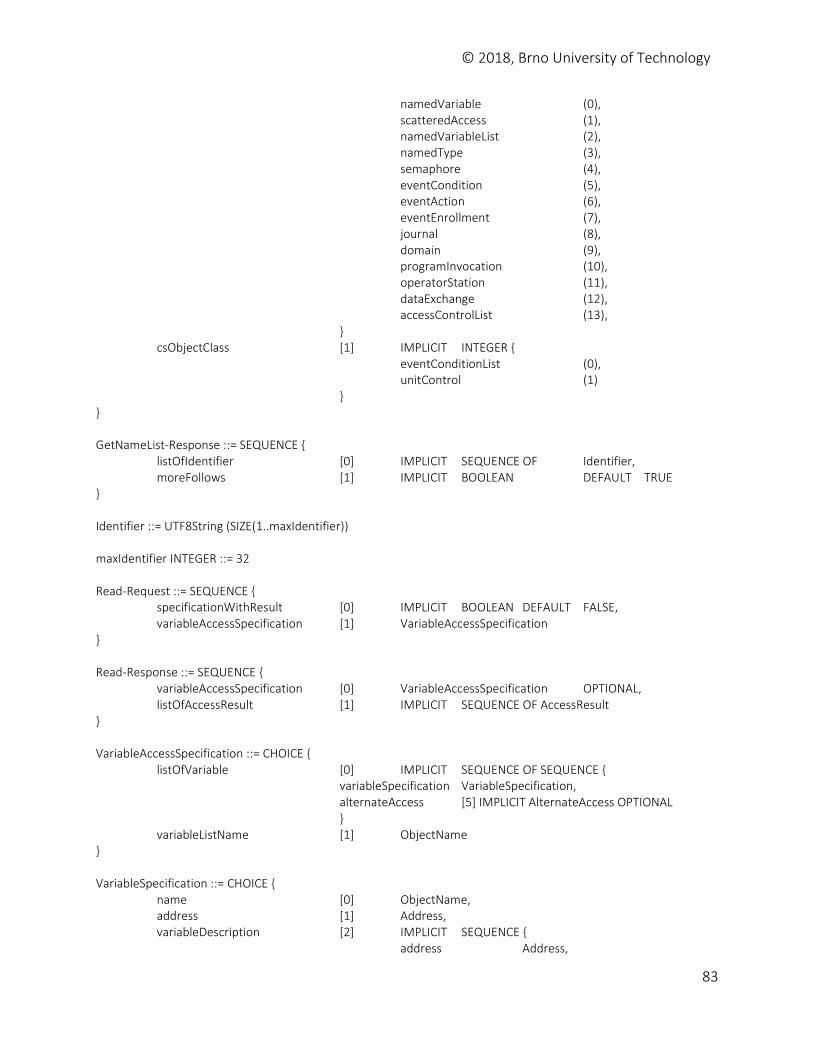
© 2018, Brno University of Technology
83
namedVariable (0), scatteredAccess (1), namedVariableList (2), namedType (3), semaphore (4), eventCondition (5), eventAction (6), eventEnrollment (7), journal (8), domain (9), programInvocation (10), operatorStation (11), dataExchange (12), accessControlList (13), } csObjectClass [1] IMPLICIT INTEGER { eventConditionList (0), unitControl (1) } } GetNameList-Response ::= SEQUENCE { listOfIdentifier [0] IMPLICIT SEQUENCE OF Identifier, moreFollows [1] IMPLICIT BOOLEAN DEFAULT TRUE } Identifier ::= UTF8String (SIZE(1..maxIdentifier)) maxIdentifier INTEGER ::= 32 Read-Request ::= SEQUENCE { specificationWithResult [0] IMPLICIT BOOLEAN DEFAULT FALSE, variableAccessSpecification [1] VariableAccessSpecification } Read-Response ::= SEQUENCE { variableAccessSpecification [0] VariableAccessSpecification OPTIONAL, listOfAccessResult [1] IMPLICIT SEQUENCE OF AccessResult } VariableAccessSpecification ::= CHOICE { listOfVariable [0] IMPLICIT SEQUENCE OF SEQUENCE { variableSpecification VariableSpecification, alternateAccess [5] IMPLICIT AlternateAccess OPTIONAL } variableListName [1] ObjectName } VariableSpecification ::= CHOICE { name [0] ObjectName, address [1] Address, variableDescription [2] IMPLICIT SEQUENCE { address Address,
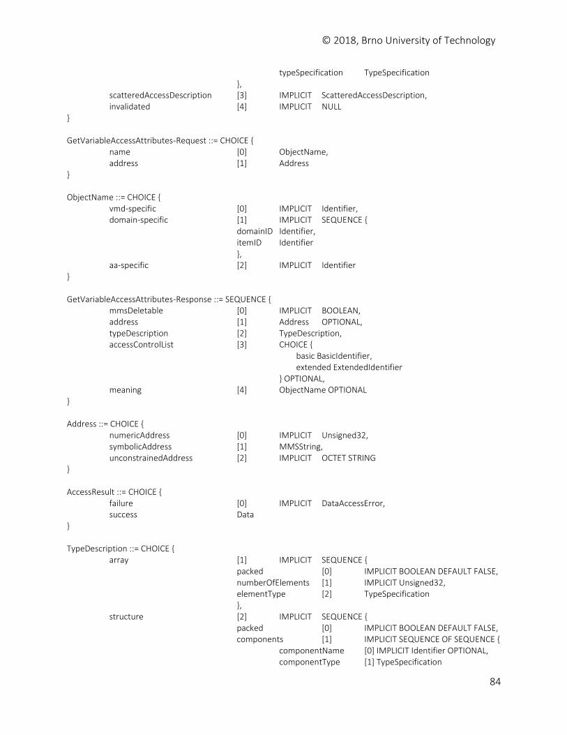
© 2018, Brno University of Technology
84
typeSpecification TypeSpecification }, scatteredAccessDescription [3] IMPLICIT ScatteredAccessDescription, invalidated [4] IMPLICIT NULL } GetVariableAccessAttributes-Request ::= CHOICE { name [0] ObjectName, address [1] Address } ObjectName ::= CHOICE { vmd-specific [0] IMPLICIT Identifier, domain-specific [1] IMPLICIT SEQUENCE { domainID Identifier, itemID Identifier }, aa-specific [2] IMPLICIT Identifier } GetVariableAccessAttributes-Response ::= SEQUENCE { mmsDeletable [0] IMPLICIT BOOLEAN, address [1] Address OPTIONAL, typeDescription [2] TypeDescription, accessControlList [3] CHOICE { basic BasicIdentifier, extended ExtendedIdentifier } OPTIONAL, meaning [4] ObjectName OPTIONAL } Address ::= CHOICE { numericAddress [0] IMPLICIT Unsigned32, symbolicAddress [1] MMSString, unconstrainedAddress [2] IMPLICIT OCTET STRING } AccessResult ::= CHOICE { failure [0] IMPLICIT DataAccessError, success Data } TypeDescription ::= CHOICE { array [1] IMPLICIT SEQUENCE { packed [0] IMPLICIT BOOLEAN DEFAULT FALSE, numberOfElements [1] IMPLICIT Unsigned32, elementType [2] TypeSpecification }, structure [2] IMPLICIT SEQUENCE { packed [0] IMPLICIT BOOLEAN DEFAULT FALSE, components [1] IMPLICIT SEQUENCE OF SEQUENCE { componentName [0] IMPLICIT Identifier OPTIONAL, componentType [1] TypeSpecification
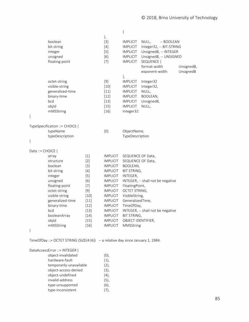
© 2018, Brno University of Technology
85
} }, boolean [3] IMPLICIT NULL, -- BOOLEAN bit-string [4] IMPLICIT Integer32, -- BIT-STRING integer [5] IMPLICIT Unsigned8, -- INTEGER unsigned [6] IMPLICIT Unsigned8, -- UNSIGNED floating-point [7] IMPLICIT SEQUENCE { format-width Unsigned8, exponent-width Unsigned8 }, octet-string [9] IMPLICIT Integer32 visible-string [10] IMPLICIT Integer32, generalized-time [11] IMPLICIT NULL, binary-time [12] IMPLICIT BOOLEAN, bcd [13] IMPLICIT Unsigned8, objId [15] IMPLICIT NULL, mMSString [16] Integer32 } TypeSpecification ::= CHOICE { typeName [0] ObjectName, typeDescription TypeDescription } Data ::= CHOICE { array [1] IMPLICIT SEQUENCE OF Data, structure [2] IMPLICIT SEQUENCE OF Data, boolean [3] IMPLICIT BOOLEAN, bit-string [4] IMPLICIT BIT STRING, integer [5] IMPLICIT INTEGER, unsigned [6] IMPLICIT INTEGER, -- shall not be negative floating-point [7] IMPLICIT FloatingPoint, octet-string [9] IMPLICIT OCTET STRING, visible-string [10] IMPLICIT VisibleString, generalized-time [11] IMPLICIT GeneralizedTime, binary-time [12] IMPLICIT TimeOfDay, bcd [13] IMPLICIT INTEGER, -- shall not be negative booleanArray [14] IMPLICIT BIT STRING, objId [15] IMPLICIT OBJECT IDENTIFIER, mMSString [16] IMPLICIT MMSString } TimeOfDay ::= OCTET STRING (SIZE(4|6)) -- a relative day since January 1, 1984. DataAccessError ::= INTEGER { object-invalidated (0), hardware-fault (1), temporarily-unavailable (2), object-access-denied (3), object-undefined (4), invalid-address (5), type-unsupported (6), type-inconsistent (7),
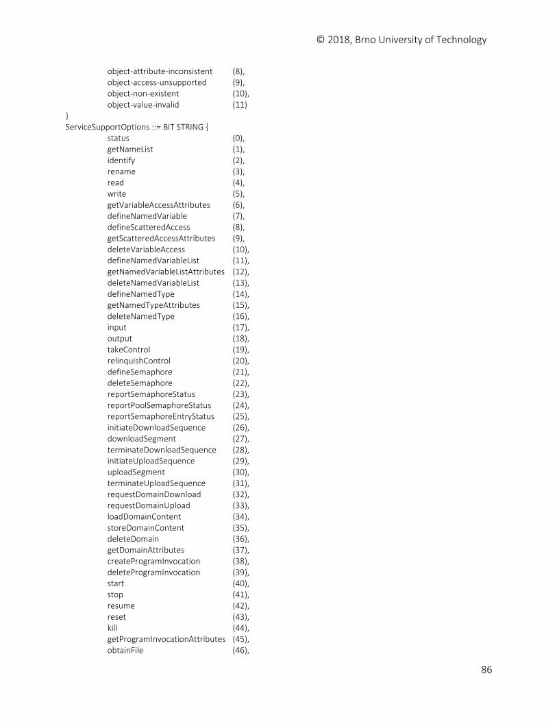
© 2018, Brno University of Technology
86
object-attribute-inconsistent (8), object-access-unsupported (9), object-non-existent (10), object-value-invalid (11) } ServiceSupportOptions ::= BIT STRING { status (0), getNameList (1), identify (2), rename (3), read (4), write (5), getVariableAccessAttributes (6), defineNamedVariable (7), defineScatteredAccess (8), getScatteredAccessAttributes (9), deleteVariableAccess (10), defineNamedVariableList (11), getNamedVariableListAttributes (12), deleteNamedVariableList (13), defineNamedType (14), getNamedTypeAttributes (15), deleteNamedType (16), input (17), output (18), takeControl (19), relinquishControl (20), defineSemaphore (21), deleteSemaphore (22), reportSemaphoreStatus (23), reportPoolSemaphoreStatus (24), reportSemaphoreEntryStatus (25), initiateDownloadSequence (26), downloadSegment (27), terminateDownloadSequence (28), initiateUploadSequence (29), uploadSegment (30), terminateUploadSequence (31), requestDomainDownload (32), requestDomainUpload (33), loadDomainContent (34), storeDomainContent (35), deleteDomain (36), getDomainAttributes (37), createProgramInvocation (38), deleteProgramInvocation (39), start (40), stop (41), resume (42), reset (43), kill (44), getProgramInvocationAttributes (45), obtainFile (46),
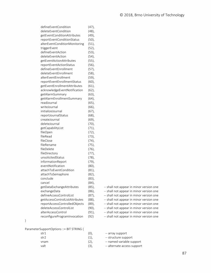
© 2018, Brno University of Technology
87
defineEventCondition (47), deleteEventCondition (48), getEventConditionAttributes (49), reportEventConditionStatus (50), alterEventConditionMonitoring (51), triggerEvent (52), defineEventAction (53), deleteEventAction (54), getEventActionAttributes (55), reportEventActionStatus (56), defineEventEnrollment (57), deleteEventEnrollment (58), alterEventEnrollment (59), reportEventEnrollmentStatus (60), getEventEnrollmentAttributes (61), acknowledgeEventNotification (62), getAlarmSummary (63), getAlarmEnrollmentSummary (64), readJournal (65), writeJournal (66), initializeJournal (67), reportJournalStatus (68), createJournal (69), deleteJournal (70), getCapabilityList (71), fileOpen (72), fileRead (73), fileClose (74), fileRename (75), fileDelete (76), fileDirectory (77), unsolicitedStatus (78), informationReport (79), eventNotification (80), attachToEventCondition (81), attachToSemaphore (82), conclude (83), cancel (84), getDataExchangeAttributes (85), -- shall not appear in minor version one exchangeData (86), -- shall not appear in minor version one defineAccessControlList (87), -- shall not appear in minor version one getAccessControlListAttributes (88), -- shall not appear in minor version one reportAccessControlledObjects (89), -- shall not appear in minor version one deleteAccessControlList (90), -- shall not appear in minor version one alterAccessControl (91), -- shall not appear in minor version one reconfigureProgramInvocation (92) -- shall not appear in minor version one } ParameterSupportOptions ::= BIT STRING { str1 (0), -- array support str2 (1), -- structure support vnam (2), -- named variable support valt (3), -- alternate access support
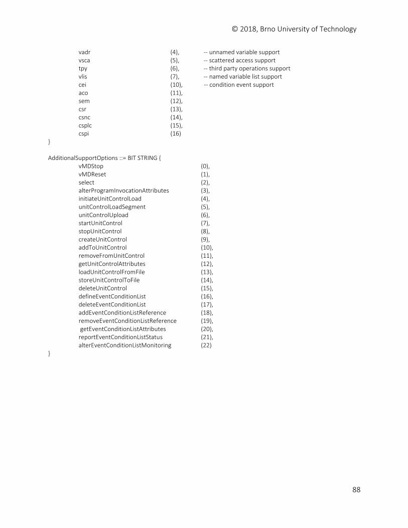
© 2018, Brno University of Technology
88
vadr (4), -- unnamed variable support vsca (5), -- scattered access support tpy (6), -- third party operations support vlis (7), -- named variable list support cei (10), -- condition event support aco (11), sem (12), csr (13), csnc (14), csplc (15), cspi (16) } AdditionalSupportOptions ::= BIT STRING { vMDStop (0), vMDReset (1), select (2), alterProgramInvocationAttributes (3), initiateUnitControlLoad (4), unitControlLoadSegment (5), unitControlUpload (6), startUnitControl (7), stopUnitControl (8), createUnitControl (9), addToUnitControl (10), removeFromUnitControl (11), getUnitControlAttributes (12), loadUnitControlFromFile (13), storeUnitControlToFile (14), deleteUnitControl (15), defineEventConditionList (16), deleteEventConditionList (17), addEventConditionListReference (18), removeEventConditionListReference (19), getEventConditionListAttributes (20), reportEventConditionListStatus (21), alterEventConditionListMonitoring (22) }