design 3024s diaphragm actuator - spartan controls/media/resources/fisher/u/394... · design 3024s...
TRANSCRIPT

www.Fisher.com
D10
2625
X01
2
Design 3024S Diaphragm ActuatorContents
Introduction 1. . . . . . . . . . . . . . . . . . . . . . . . . . . . . . . Scope of Manual 1. . . . . . . . . . . . . . . . . . . . . . . . . . . Description 1. . . . . . . . . . . . . . . . . . . . . . . . . . . . . . . . Specifications 2. . . . . . . . . . . . . . . . . . . . . . . . . . . . . Installation 3. . . . . . . . . . . . . . . . . . . . . . . . . . . . . . . .
Actuator Mounting 4. . . . . . . . . . . . . . . . . . . . . . . . Travel Adjustments 5. . . . . . . . . . . . . . . . . . . . . . .
Maintenance 5. . . . . . . . . . . . . . . . . . . . . . . . . . . . . . Disassembly 5. . . . . . . . . . . . . . . . . . . . . . . . . . . . . Assembly 6. . . . . . . . . . . . . . . . . . . . . . . . . . . . . . . . Changing Actuator Action 7. . . . . . . . . . . . . . . . . . Side Mounted Handwheel 7. . . . . . . . . . . . . . . . . Adjustable Travel Stops 9. . . . . . . . . . . . . . . . . . .
Parts Ordering 11. . . . . . . . . . . . . . . . . . . . . . . . . . . . Parts List 11. . . . . . . . . . . . . . . . . . . . . . . . . . . . . . .
Introduction
Scope of ManualThis instruction manual provides information oninstallation, adjustment, maintenance and partsordering for the Type GA 1.21, GA 1.31 and GA 1.41actuators.
DescriptionThe direct acting (extends stem) actuator (figure 6and 9) and the reverse acting (retracts stem)actuators (figure 7 and 10) are spring-opposedpneumatic diaphragm actuators that providethrottling or on-off operation of sliding-stem controlvalves. The Type 3024S ATC actuator springs are
Figure 1. Type 3024S Actuator with Design 1018S Valve.
W6681B
located under the diaphragm plate, and they fullyretract the actuator stem for fail action upon loss ofdiaphragm casing pressure. The Type 3024S ATOactuator springs are located on top of the diaphragmplate, and they fully extend the actuator stem uponloss of diaphragm casing pressure.
Only personnel qualified through training orexperience should install, operate and maintain Type3024S actuators.
Instruction ManualForm 5421June 1999 Design 3024S Actuator

Design 3024S ActuatorInstruction Manual
Form 5421June 1999
2
Table 1. Specifications
Actuator Sizes
GA1.21GA 1.31GA 1.41
Maximum Actuator Travels
Size GA 1.21 and GA 1.31: 16 mm (0.63 inch)
Size GA 1.31 and GA 1.41 : 32 mm (1.26 inch)
Standard Operating Pressure Range
See table 2a (ATC) and 2b (ATO)
Maximum Operating Pressure
See table 2a (ATC) and 2b (ATO)
Maximum Output Thrust
(Maximum Actuator Stem Force)See table 2a (ATC) and 2b (ATO)
Material Temperature CapabilitiesWith Nitrile Diaphragm and Steel studs and nuts : -40�C to +90�C (-40�F to 194�F)
Signal ConnectionsStandard: G1/4 inch Withworth female thread(ISO 7-1/BS 21/DIN2999)
Actuator Stem DiametersSize GA 1.21 and GA 1.31: 12mm (0.472 inch)Size GA 1.41: 16mm (0.630 inch)
Acceptable Valve Stem ThreadsSize GA 1.21 and GA 1.31: M12 X 1.75 (2 1/8”yoke boss & 16mm travel)Size GA 1.31 and GA 1.41: M16 X 2 (2 13/16”yoke boss & 32mm travel)
Approximate WeightsSize GA 1.21: 7.1 kg (15.6 pounds)Size GA 1.31: 16.5 kg (36.4 pounds)Size GA 1.41: 33.5 kg (73.9 pounds)
SpecificationsSpecifications for the Type 3024S actuators are
shown in table 1. Some of the specifications for agiven actuator assembly as it originally comes fromthe factory are stamped on a nameplate (figure 2.)attached to the actuator.
Figure 2. Type 3024S Actuator Nameplate
E0798
Design 3024S ActuatorInstruction ManualForm 5421June 1999
3
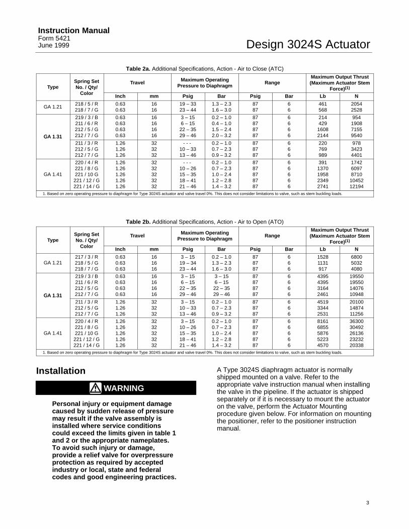
Table 2a. Additional Specifications, Action - Air to Close (ATC)
TypeSpring SetNo. / Qty/
Travel Maximum OperatingPressure to Diaphragm
RangeMaximum Output Thrust(Maximum Actuator Stem
Force)(1)Color Inch mm Psig Bar Psig Bar Lb N
GA 1.21 218 / 5 / R218 / 7 / G
0.630.63
1616
19 – 3323 – 44
1.3 – 2.31.6 – 3.0
8787
66
461568
20542528
GA 1.31
219 / 3 / B211 / 6 / R212 / 5 / G212 / 7 / G
0.630.630.630.63
16161616
3 – 156 – 15
22 – 3529 – 46
0.2 – 1.00.4 – 1.01.5 – 2.42.0 – 3.2
87878787
6666
21442916082144
954190871559540GA 1.31
211 / 3 / R212 / 5 / G212 / 7 / G
1.261.261.26
323232
- - - 10 – 3313 – 46
0.2 – 1.00.7 – 2.30.9 – 3.2
878787
666
220769989
97834234401
GA 1.41
220 / 4 / R221 / 8 / G221 / 10 G
221 / 12 / G221 / 14 / G
1.261.261.261.261.26
3232323232
- - - 10 – 2615 – 3518 – 4121 – 46
0.2 – 1.00.7 – 2.31.0 – 2.41.2 – 2.81.4 – 3.2
8787878787
66666
3911370195823492741
174260978710
1045212194
1. Based on zero operating pressure to diaphragm for Type 3024S actuator and valve travel 0%. This does not consider limitations to valve, such as stem buckling loads.
Table 2b. Additional Specifications, Action - Air to Open (ATO)
TypeSpring SetNo. / Qty/
Travel Maximum OperatingPressure to Diaphragm
RangeMaximum Output Thrust(Maximum Actuator Stem
Force)(1)Color Inch mm Psig Bar Psig Bar Lb N
GA 1.21217 / 3 / R218 / 5 / G218 / 7 / G
0.630.630.63
161616
3 – 1519 – 3423 – 44
0.2 – 1.01.3 – 2.31.6 – 3.0
878787
666
15281131917
680050324080
GA 1.31
219 / 3 / B211 / 6 / R212 / 5 / G212 / 7 / G
0.630.630.630.63
16161616
3 – 156 – 15
22 – 3529 – 46
3 – 156 – 15
22 – 3529 – 46
87878787
6666
4395439531642461
19550195501407610948GA 1.31
211 / 3 / R212 / 5 / G212 / 7 / G
1.261.261.26
323232
3 – 1510 – 3313 – 46
0.2 – 1.00.7 – 2.30.9 – 3.2
878787
666
451933442531
201001487411256
GA 1.41
220 / 4 / R221 / 8 / G221 / 10 G
221 / 12 / G221 / 14 / G
1.261.261.261.261.26
3232323232
3 – 1510 – 2615 – 3518 – 4121 – 46
0.2 – 1.00.7 – 2.31.0 – 2.41.2 – 2.81.4 – 3.2
8787878787
66666
81616855587652234570
3630030492261362323220338
1. Based on zero operating pressure to diaphragm for Type 3024S actuator and valve travel 0%. This does not consider limitations to valve, such as stem buckling loads.
Installation
WARNING
Personal injury or equipment damagecaused by sudden release of pressuremay result if the valve assembly isinstalled where service conditionscould exceed the limits given in table 1and 2 or the appropriate nameplates.To avoid such injury or damage,provide a relief valve for overpressureprotection as required by acceptedindustry or local, state and federalcodes and good engineering practices.
A Type 3024S diaphragm actuator is normallyshipped mounted on a valve. Refer to theappropriate valve instruction manual when installingthe valve in the pipeline. If the actuator is shippedseparately or if it is necessary to mount the actuatoron the valve, perform the Actuator Mountingprocedure given below. For information on mountingthe positioner, refer to the positioner instructionmanual.

Design 3024S ActuatorInstruction Manual
Form 5421June 1999
4
CAUTION
The Type 3024S actuators aredesigned to mount onpush-down-to-close valves. Do notmount these actuators on any othertype of valve without first contactingthe Fisher sales office.
Actuator MountingThe following procedure describes how to mount aType 3024S actuator on a push-down-to-close valveso that the actuator stem and valve stem threadengagement allows full travel and proper shutoff.Refer to figure 5 for actuator dimensions. Keynumbers referenced in the following steps are shownin figures 6, 7, 9 & 10.
1. Thread the stem hex nut (key 54/52) first andthen the connector (key 50) onto the valve stem andrun them down.
2. Push the valve stem down until the valve plug isfully closed.
3. Carefully place the actuator with the flange (key45) on the valve bonnet.
WARNING
When moving the actuator stem withdiaphragm loading pressure usecaution to keep hands and tools out ofthe actuator stem travel path. Personalinjury and/or property damage ispossible if something is caughtbetween the actuator stem and othercontrol valve assembly parts.
CAUTION
Be sure that the length of the actuatorstem or the valve stem in theconnector (key 50 or 53) is equal to orgreater than the diameter of that stem.
In the following procedure, do notrotate the valve plug while it is seated.This may damage the seating surfaceand thereby allow excessive leakage.Also, during adjustment, use toolscarefully to avoid damaging the valve
stem. A damaged stem could cut thepacking and allow leakage.
4. Perform one of the following procedures asappropriate:
For a Type 3024S Air-To-Close actuator with apush-down-to-close valve:
a. Tighten the valve bonnet lock nut.
b. Adjust the travel: rotate the connector halves(key 53 and 50) so that the distance betweenthem (with the valve on the seat and the travelindicator-key 51 between the connectors) is equalto the valve travel.
c. Pressurise the actuator slowly and adjust thestem connector half (key 50) so the connectingbolts will line up.
d. Tighten all bolts (key 55/56) and nuts (key56/57).
e. Apply bench set pressure to the top of thediaphragm and check the valve stem travel.
f. Tighten the valve stem hex nut (key 54/52)against the stem connector (key 50).
For a Type 3024S Air-To-Open actuator with apush-down-to-close valve:
a. Apply approximately 0.5 bar above the highestsetting of the bench set pressure to the bottom ofthe diaphragm. This positions the actuator stem(key 8) at the highest point.
b. Tighten the valve bonnet lock nut.
c. Adjust the travel: rotate the connector halves(key 53 and 50) so that the distance betweenthem (with the plug on the seat and the travelindicator key 51 between the connectors) is equalto the valve travel.
d. Exhaust the actuator slowly and adjust thestem connector half (key 50) so the connectingbolts will line up.
e. Completely exhaust the actuator and tightenall bolts (key 55/56) and nuts (key 56/57).
f. Apply approximately 0.5 bar above the highestbench set pressure to the top of the diaphragmand check the valve stem travel.
g. Tighten the valve stem hex nut (key 54/52)against the stem connector (key 50).

Design 3024S ActuatorInstruction ManualForm 5421June 1999
5
For a Type 3024S Air-To-Open & Air-To-Closeactuators:
5. Cycle the actuator several times to check forproper operation.
6. Adjust the travel indicator scale (key 26) up ordown to correspond with the travel indicator.
Travel AdjustmentsAlthough making travel adjustments should not benecessary if previous section on Actuator Mountinghas been followed, use the following procedurewhen the actuator travel is different from thatstamped on the actuator nameplate (figure 2).
When adjusting the travel of a push-down-to-closevalve air-to-open actuator combination, slightlypressurise the actuator. This moves the valve plugoff the seat, reducing the chance of damaging thevalve plug or seat during adjustment.
1. Back off the stem hex nut (key 54/52) from thevalve stem connector, and slightly loosen both/all 4cap screws (key 55/56) from the connectors.
2. Screw the connector (key 50) clockwise (tolengthen travel) or counter-clockwise (to shortentravel).
3. Tighten the stem connector cap screw (key55/56).
4. Cycle the actuator to check for the specifiedtravel. If the travel is not equal to the specified travel,adjust and check it until it is correct. Tighten thestem hex nut (key 54/52) against the stemconnector.
MaintenanceActuator parts are subject to normal wear and mustbe inspected and replaced as necessary. Thefrequency of inspection and replacement dependsupon the severity of the service conditions. Due tothe care Fisher takes in meeting manufacturingrequirements (heat treating, dimensional tolerances,etc.), use only replacement parts manufactured orfurnished by Fisher.
This section describes how the actuator can becompletely disassembled and assembled. Wheninspection or repairs are required, disassemble only
those parts necessary to accomplish the job; thenstart the assembly at the appropriate step.
Key numbers refer to figure 6 for a Size 1.21/1.31Air-To-Close actuator, to figure 7 for a 1.21/1.31Air-To-Open actuator, figure 9 for a Size 1.41Air-To-Close actuator, to figure 10 for a 1.41Air-To-Open actuator.
Disassembly
WARNING
Avoid personal injury or damage toproperty from sudden release ofpressure, uncontrolled process fluid,or precompressed spring force. Beforestarting disassembly:
� Isolate the valve from theprocess,
� Release process pressure,
� Vent all internal pressure from theactuator,
� Release all spring preloadingforce,
� Use lock-out procedures to besure that the above measures stay ineffect while you work on theequipment.
1. For complete disassembly, the positioner and allaccessories (if attached) must be removed from theactuator. Follow the appropriate removal proceduresin the instruction manuals supplied with thepositioner and accessories.
2. Bypass the control valve. Reduce the loadingpressure to atmospheric, and for a bottom-loadedType 3024S Air-To-Open actuator, remove thetubing or piping from the connection in the lowerdiaphragm casing (key 1).For a top-loaded Type 3024S Air-To-Close actuator,remove the piping or tubing from the connection inthe upper diaphragm casing (key 16).
3. Slightly loosen all diaphragm casing cap screws(key 19 and 21). Remove the plastic hose (key 22).Unscrew the short and long diaphragm casing capscrews and nuts (key 19, 20 and 21) alternately, untilonly the long casing cap screws (key 21) remainengaged. Then allow the remaining springcompression to be slowly and evenly released byalternately unscrewing the long casing cap screws.

Design 3024S ActuatorInstruction Manual
Form 5421June 1999
6
4. When removing the diaphragm and actuatorsprings perform one of the following procedures asappropriate:
For a Type 3024S Air-To-Open actuator (figure 7 & 10):
a. Lift off the upper diaphragm casing (key 16)and remove the springs (key 15).
b. Using a strap wrench or soft-jawed vice andthe actuator stem (key 8), remove the hex nut(key 14).
c. Remove the diaphragm plate (key 13),diaphragm (key 11), O-Ring (key 12), pressureplate (key 10) and the ring halves (key 9).
For a Type 3024S Air-To-Close actuator (figure 6 &9) :
a. Lift off the upper diaphragm casing (key 16).
b. Using a strap wrench or soft-jawed vice andthe actuator stem (key 8), remove the hex nut(key 14).
c. Remove the pressure plate (key 10), O-Ring(key 12), diaphragm (key 11) , diaphragm plate(key 13) and the ring halves (key 9).
d. Remove the springs (key 15).
1. Carefully slide the actuator stem (key 8) out thebottom of the lower diaphragm casing (key 1) andset it on a protective surface to prevent damage tothe O-ring sealing surface.
2. Remove the bellow (key 31), if used.
3. Unscrew the cheese head screws (key 7), thenremove the bushing (key 6).
4. With the actuator disassembled, inspect all partsfor excessive wear and replace as necessary.
AssemblyThis procedure assumes that the actuator iscompletely disassembled. If it is not, start theinstructions at the appropriate step.
For a Type 3024S Air-To-Open & Air-To-Closeactuator :
1. Before starting assembly, apply LubriplateMAG-1 lubricant or equivalent to the O-ring (in thebushing key 6 and key 12). Install the new bushing(key 6) and assemble with the cheese head screws
(key 7) onto the lower diaphragm casing (key 1).Use a torque of 0.4 N�m (0.25 lbf�ft)
2. Carefully slide the actuator stem (key 8) downthrough the bushing (key 6) .
3. When installing the diaphragm and actuatorsprings perform one of the following procedures asappropriate:
For a Type 3024S Air-To-Open:
a. Assemble the ring halves (key 9), pressureplate (key 10), O-Ring (Key 12), diaphragm (Key11) and diaphragm plate (key 13) as shown infigure 7 or 10.
b. Apply Loctite 271 or equivalent to the actuatorstem travel stop thread and tighten the travel stopas follows: Sizes GA 1.21/1.31 tighten to 37 N�m(28 lbf�ft), size GA 1.41 tighten to 90 N�m (66lbf�ft).
c. Position the actuator springs (key 15)symmetrical on the diaphragm plate (key 13) asshown in figure 3.
For a Type 3024S Air-To-Close:
a. Assemble the ring halves (key 9), pressureplate (key 10), O-Ring (Key 12), diaphragm (Key11) and diaphragm plate (key 13) as shown infigure 6 or 9.
b. Apply Loctite or equivalent to the actuatorstem travel stop thread and tighten the travel stopas follows: Sizes GA 1.21/1.31 tighten to 37 N�m(28 lbf�ft), size GA 1.41 tighten to 90 N�m (66lbf�ft).
c. Position the actuator springs (key 15)symmetrical on the diaphragm plate (key 13) asshown in figure 3.
CAUTION
Overtightening the diaphragm capscrews and nuts can damage thediaphragm. Do not exceed a torque of11 N�m (8 lbf�ft) for Size GA 1.21 and16 N�m (12 lb�ft) for sizes GA 1.31 &1.41.

Design 3024S ActuatorInstruction ManualForm 5421June 1999
7
For a Type 3024S Air-To-Close & Air-to-Open:
4. Install the upper diaphragm casing (key 16) usingthe long cap screws (key 21) and hex nuts (key 20)first. Then secure with cap-screws (key 19) and hexnuts (key 20). Be sure the supply connection islocated directly above the vent in the lowerdiaphragm. Fit the plastic hose (key 22) over the capscrews (key 21).
Note
Be sure to use the long cap screws(key 21), first installing them on theopposite sides of the diaphragmcasing. Tighten them evenly, using acrisscross pattern to ensure a properseal.
5. Mount the actuator on the valve in accordancewith the Installation procedures.
Changing Actuator Action
The Actuator can be changed from a Type 3024SATO to a 3024 ATC or vice versa by removing thepressure plate, diaphragm, O-ring, diaphragm plate,hex nut, springs, spring locator, self tapping screwsand vent assembly (key 10, 11, 12, 13, 14, 15, 17,18 and 23) and installing them for appropriate action.See figures 6, 7, 9 and 10. For hex nut or travel stop(key 14) and pressure plate (key 10) selection referto parts list. Follow the procedures in the ActuatorMounting section and the Travel Adjustment sectionfor connection to the valve.
Side-Mounted Handwheel
A side-mounted handwheel assembly (figure 4) isusually used as a manual operator. When mountedon an ATC type 3024S actuator, turning thehandwheel clockwise always closes the valve. Whenmounted on an ATO actuator, turning the handwheelclockwise always opens the valve, A lever (key 49,figure 12) on the handwheel assembly opens orcloses the valve by moving the valve stem.
Instructions are given below for completedisassembly and assembly. Perform thedisassembly only as far as necessary to accomplishthe required maintenance; then begin the assemblyat the appropriate step.
Refer to figure 12 for key numbers.
Disassembly1. If desired, the handwheel assembly can beremoved from the actuator leg post. To do this,remove the hex nuts (key 62) and back plates (key64) from the U-bolts (key 61) that hold the assemblyto the leg-post.
2. Loosen the lock (key 63) that secures the drivescrew assembly (key 51).
3. Remove the retaining ring (key 58) and screw outthe drive screw assembly (key 51).
4. Remove the retainer ring (key 56) and drive outthe pivot pin (key 52).
5. Remove the bushings (key 55) from the body(key 48).
6. There is a cap screw (key 59), hex nut (key 60),and spacer (key 53) that hold the two levers (key 49)together. Remove the cap screw and hex nut andthe two levers can be separated in order to removethe operating nut (key 50).
Assembly1. Assemble the operating nut (key 50), the twolevers (key 49), and the spacer (key 53) using thecap screw (key 59) and hex nut (key 60).
2. Install the bushings (key 55) in the body (key 48).
3. Attach the levers (key 49) to the body (key 48)using the pivot pin (key 52) and the retaining ring(key 56).
4. Apply lubricant Lubriplate MAG-1 or equivalent tothe drive screw assembly (key 51) and screw it on tothe operating nut (key 50).
5. Install the retaining ring (key 58. to secure thecollar to the body (key 48).
6. If the handwheel assembly was removed from theactuator leg posts, position the U-bolts (key 61),back plate (key 64) and handwheel body (key 48) tothe actuator leg posts as shown in figures 3 & 12.Tighten the hex nuts (key 62) to 19 N�m (14 lbf�ft).Clearance between the lower diaphragm casing andthe handwheel body are shown in figure 4. With theactuator fully open the distance between the lowerface of the actuator stem connector and the actuatorflange should be shown in figure 4.

Design 3024S ActuatorInstruction Manual
Form 5421June 1999
8
Figure 3. Type 3024S Spring Arrangements.E0799

Figure 4. Type 3024S Actuator Handwheel Mounting (GA 1.21 and 1.31 Only).
TYPE 3024SAIR-TO-CLOSE
TYPE 3024SAIR-TO-OPENE0800
A A
BB
Design 3024S ActuatorInstruction ManualForm 5421June 1999
9
A BActuator Size Travel (mm)
Millimeters
GA 1.21 16 15 112
GA 1.31 16 5 112
GA 1.41 32 10 123
Inches
GA 1.21 16 1/2 4–1/2
GA 1.31 32 1/4 4–1/2
GA 1.41 32 1/2 5
Adjustable Travel Stops
The adjustable up travel stop (figure 8) for GA 1.21and 1.31 actuators limits the actuator stroke in theupward direction (limits retraction of the actuatorstem).Loosen the hex nut (key 25) and turn the adjuster(key 24) clockwise into the diaphragm case to movethe actuator stem downward or counter-clockwise toallow the actuator stem to move upward. Since thevalve has push-down-to-close action, full openingcan be restricted. Check the actuator travel and thentighten the hex nut (key 25).
For the GA 1.41 actuator up travel stop key numbersreferenced in the following steps are shown in figure11.
1. Loosen the head screws (key 8)
2. Unscrew the cap screws and nuts (key 5 and 7)and remove the cover plate (key 4)
3. Loosen the head screw (key 2) and turn thebushing (key 3) clockwise into the adjustment nut(key 1) to allow the actuator stem to move upward orcounter clockwise to shorten the actuator travel.
4. Check the actuator travel and then tighten thehead screw (key 2).
5. Assemble the cover plate (key 4) and tighten thecap screws and nuts (key 5 and 7).
CAUTION
In the following adjustmentprocedures, take care to avoid injurywhile positioning components.
6. Adjust the cover plate (key 4) so that there is nogap between the diaphragm case and the coverplate.
7. Tighten the head screw (key 8).

Figure 5. Actuator Dimensions (Reverse Acting).
����������� ����������
AR
E
F
C
E0801
Design 3024S ActuatorInstruction Manual
Form 5421June 1999
10
Actuator TravelC
DiameterE F AR
Size (mm)Millimeters
GA 1.21 16 215 360(1)
16 315 450105
GA 1.3132 315 480
45
GA 1.41 32 420 515133
Inches
GA 1.21 16 8.46 14.17
16 12.40 17.724.13
GA 1.3132 12.40 18.90
1.77
GA 1.41 32 16.54 20.285.24
1. Without lifting ring.

Design 3024S ActuatorInstruction ManualForm 5421June 1999
11
Parts OrderingEach actuator has a serial number stamped on thenameplate (figure 2 and key 34, figure 6, 7 and 10).Refer to the serial number when orderingreplacement parts or when corresponding with yourFisher sales office or sales representative fortechnical assistance. Also, specify the complete 7 or11-character part number from the following parts listwhen ordering replacement parts.
Parts List
ActuatorKey Description Part Number1 Lower Diaphragm Casing, steel
Size GA 1.21 0410632Size GA 1.31 0449660Size GA 1.41 0449687
3* Gasket (2 required)Size GA 1.21 0409081Size GA 1.31 & 1.41 0411426
4 Supporting Ring, steelSize GA 1.21 - - - Size GA 1.31 & 1.41 (2 required) 0411434
5 Leg Post, steel (2 required)Size GA 1.21, Travel 16mm 0409090Size GA 1.31, Travel 16mm 1066803Size GA 1.31 & 1.41 , Travel 32mm 2539667
6* BushingSize GA 1.21 & 1.31 0409065Size GA 1.41 0411159
7 Cheese Head Screw, stainless steel (6 required) 0119512
8 Actuator Stem, stainless steel Size GA 1.21 0410713Size GA 1.31 0410284Size GA 1.41 0411752
9 Ring Half, stainless steel (2 required)Size GA 1.21 & 1.31 0410365Size GA 1.41 0411876
10 Pressure PlateSize GA 1.21, aluminium ATO and ATC 1136879Size GA 1.31, steel, Travel 16 mm0.2 - 1.0 bar (3 - 15 psig) ATO and ATC 04103730.4 - 1.0 bar (6 - 15 psig) ATO and ATC 04103731.5 - 2.4 bar (22 - 35 psig) ATO 21398391.5 - 2.4 bar (22 - 35 psig) ATC 04103732.0 - 3.2 bar (29 - 46 psig) ATO 21398392.0 - 3.2 bar (29 - 46 psig) ATC 0410373Size GA 1.31, steel, Travel 32 mm, ATO and ATC 0410373Size GA 1.41, steel, ATO and ATC 0411884
11* Diaphragm, nitrileSize GA 1.21 0410705Size GA 1.31 0410357Size GA 1.41 0411868
Key Description Part Number12* O-Ring, nitrile
Size GA 1.21 & 1.31 0409073Size GA 1.41 0411736
13 Diaphragm PlateSize GA 1.21, aluminium 1136887Size GA 1.31, aluminium 2631032Size GA 1.41, cast iron 0444987
14 Hex Nut, steelSize GA 1.21, Travel 16mm1.3 - 2.3 bar (19 - 34 psig) ATO 08289391.6 - 3.0 bar (23 - 44 psig) ATO 08286610.2 - 1.0 bar (3 - 15 psig) ATC 04769861.3 - 2.3 bar (19 - 34 psig) ATC 04769861.6 - 3.0 bar (23 - 44 psig) ATC 0828939Size GA 1.31, Travel 16mm0.2 - 1.0 bar (3 - 15 psig) ATO 04111080.2 - 1.0 bar (3 - 15 psig) ATC 04769860.4 - 1.0 bar (6 - 15 psig) ATO and ATC 04111081.5 - 2.4 bar (22 - 35 psig) ATO 01275151.5 - 2.4 bar (22 - 35 psig) ATC 04111082.0 - 3.2 bar (29 - 46 psig) ATO 01275152.0 - 3.2 bar (29 - 46 psig) ATC 0828661Size GA 1.31, Travel 32 mm, ATO and ATC0.2 - 1.0 bar (3 - 15 psig) 04769860.7 - 2.3 bar (10 - 33 psig) 01275150.9 - 3.2 bar (13 - 46 psig) 0127515Size GA 1.41, Travel 32 mm0.2 - 1.0 bar (3 - 15 psig) ATO and ATC 17682470.7 - 1.8 bar (11-26 psig) ATO 01275310.7 - 1.8 bar (11-26 psig) ATC 17682471.0 - 2.4 bar (15-35 psig) ATO and ATC 01275311.2 - 2.8 bar (17-41 psig) ATO and ATC 01275311.4 - 3.2 bar (20-46 psig) ATO and ATC 0127531
15 Spring, steelSize GA 1.2, Travel 16 mm0.2 - 1.0 bar ( 3 - 15 psig) (3 required) 04108531.3 - 2.3 bar (19 - 34 psig) (5 required) 04108611.6 - 3.0 bar (23 - 44 psig) (7 required) 0410861Size GA 1.31, Travel 16 mm0.2 - 1.0 bar ( 3 - 15 psig) (3 required) 04110860.4 - 1.0 bar ( 6 - 15 psig) (6 required) 04091111.5 - 2.4 bar (22 - 35 psig) (5 required) 04104112.0 - 3.2 bar (29 - 46 psig) (7 required) 0410411Size GA 1.31, Travel 32 mm 0.2 - 1.0 bar ( 3 - 15 psig) (3 required) 04091110.7 - 2.3 bar (10 - 33 psig) (5 required) 04104110.9 - 3.2 bar (29 - 46 psig) (7 required) 0410411Size GA 1.41, Travel 32 mm0.2 - 1.0 bar ( 3 - 15 psig) (4 required) 04111240.7 - 1.8 bar (11 - 26 psig) (8 required) 04111321.0 - 2.4 bar (15 - 35 psig) (10 required) 04111321.2 - 2.8 bar (17 - 41 psig) (12 required) 04111321.4 - 3.2 bar (20 - 46 psig) (14 required) 0411132
16 Upper Diaphragm Casing, steelSize GA 1.21 0410756Size GA 1.31 0411060Size GA 1.41 0412007For adjustable up stop (optional)Size GA 1.21 0478873Size GA 1.31 0478865
17 Spring Locator, stainless steelSize GA 1.21 0411604Size GA 1.31 0410322Size GA 1.41 0411809
*Recommended spare parts

Design 3024S ActuatorInstruction Manual
Form 5421June 1999
12
Figure 6. Size GA 1.21 and 1.31 Direct-Acting Actuator (ATC).
FOR 32 mm TRAVEL, USE KEY 52 HERE INSTEAD OF KEY 54.
Figure 7. Size GA 1.21 and 1.31 Reverse-Acting Actuator(ATO).
Figure 8. Adjustable Up Travel Stop for Size GA 1.21 and 1.31.
�������������������������� ��
�������������������������� ��
E0802
E0803
E0804
E0805
1
1

Design 3024S ActuatorInstruction ManualForm 5421June 1999
13
Figure 9. Size GA 1.41 Direct-Acting Actuator (ATC). Figure 10. Size GA 1.41 Reverse-Acting Actuator (ATO).
Figure 11. GA 1.41 Adjustable Up Travel Stop
E0806
E0807
E0808 E0809
� ����������������

Design 3024S ActuatorInstruction Manual
Form 5421June 1999
14
Key Description Part Number18 Convex Fillister Head Screw,
steel (2 required) 041040319 Cap Screw, steel
Size GA 1.21 (7 required) 0125385Size GA 1.31 (12 required) 0125490Size GA 1.41 (17 required) 0125490
20 Hex Nut, steelSize GA 1.21 (10 required) 0127485Size GA 1.31 (15 required) 0127493Size GA 1.41 (20 required) 0127493
21 Hex Cap Screw, steel (3 required)Size GA 1.21 0467235Size GA 1.31 0464651Size GA 1.41 0464643
22 Plastic Hose, PVC (3 required)Size GA 1.21 0479748Size GA 1.31 0479730Size GA 1.41 0479721
23 Vent Assembly, plastic 041023324 Hex Cap Screw, steel 1.21 & 1.31 (optional) 012562825 Hex Nut, steel 1.21 & 1.31 (optional) 0410993
26 Travel Indicator Scale, stainless steelSize GA 1.21, Travel 16 mm 2492431Size GA 1.31, Travel 16 mm 2492474Size GA 1.31, Travel 32 mm 2492466
27 Nut 10B1272X01228 Screw 19A4786X012
30 Hex Nut, steel (2 required) 012753131* Bellows 040915433 Warning Label 044437534 Nameplate, stainless steel 247250335 Tab Washer, stainless steel
Size GA 1.21 1167731Size GA 1.31 & 1.41 1167758
45 Actuator flange, steel2 1/8” Yoke Boss (Travel 16 mm) 24843072 13/16” Yoke Boss (Travel 32 mm) 2539659
50 Valve Stem Connector, steelWithout Side Mounted HandwheelSize GA 1.21, Travel 16 mm, ATO and ATC 0319678Size GA 1.31, Travel 16 mm0.2 - 1.0 bar (3 - 15 psig) ATO 03196780.2 - 1.0 bar (3 - 15 psig) ATC 15948420.4 - 1.0 bar (6 - 15 psig) ATO 03196780.4 - 1.0 bar (6 - 15 psig) ATC 15948421.5 - 2.4 bar (22 - 35 psig) ATO and ATC 15948422.0 - 3.2 bar (29 - 46 psig) ATO and ATC 1594842Size GA 1.31, Travel 32 mm, ATO and ATC 0458112Size GA 1.41, Travel 32 mm, ATO and ATC 0458112With Side Mounted HandwheelSize GA 1.21, Travel 16mm ATO and ATC 0319678Size GA 1.31, Travel 16mm ATO and ATC 0319678Size GA 1.31, Travel 32mm ATO and ATC 0458112
Key Description Part Number51 Travel Indicator 045818052 Hex nut, GA 1.31, Travel 32 mm (1 required) 012753153 Actuator Stem Connector, steel
Without Side Mounted HandwheelSize GA 1.21, Travel 16 mm ATO and ATC 1594842Size GA 1.31, Travel 16 mm 0.2 – 1.0 bar (3 – 15 psig) ATO and ATC 15948420.4 – 1.0 bar (6 – 15 psig) ATO and ATC 15948421.5 – 2.4 bar (22 – 35 psig) ATO 04581201.5 – 2.4 bar (22 – 35 psig) ATC 15948422.0 – 3.2 bar (29 – 46 psig) ATO 04581202.0 – 3.2 bar (29 – 46 psig) ATC 1594842Size GA 1.31, Travel 32 mm, ATO and ATC 0458120Size GA 1.41, Travel 32 mm0.2 – 1.0 bar (3 – 15 psig) ATO and ATC 0458112All except 0.2 – 1.0 bar ATO and ATC 0458139With Side Mounted HandwheelSize GA 1.21, Travel 16mm ATO and ATC 0319678Size GA 1.31, Travel 16mm ATO and ATC 1594842Size GA 1.31, Travel 32mm ATO and ATC 1594842
54 Hex Nut, steelSize GA 1.21 & 1.31, Travel 16 mm (2 required) 0127515Size GA 1.31, Travel 32 mm (1 required) 0127515Size GA 1.41 (2 required) 0127531
55 Hex Cap Scres, steel (2 required)Without Side-Mounted Handwheel 0125512With Side-Mounted Handwheel 1Q39761F012
56 Hex Nut, steel Size GA 1.21 & 1.31 (2 required) 0127493Size GA 1.41 (4 required) 0127493
57 Hex Cap Screw, steel (2 required)Size GA 1.41 0125490
60 Adjustable up travel stop for Size 1.41 (Optional)1 Nut, adjustment (1 required) 06258502 Cap Screw (1 required) 01195043 Bush 06258764 Cover Plate (2 required) 16077585 Cap Screw 02622266 Washer 01207667 Hex nut 01277528 Cap screw 0450367
*Recommended spare parts

Design 3024S ActuatorInstruction ManualForm 5421June 1999
15
Figure 12. Size-Mounted Handwheel for Type 3024S GA 1.21 and 1.31 Actuators.
49A7913
Key Description Part Number
Side Mounted Handwheel (GA 1.21 &1.31 only)48 Body, steel 49A7900X01249 Lever, steel 231743550 Operating Nut, brass 231744351 Drive Screw Assembly, steel/stainless steel
GA 1.21 29A7908X012GA 1.31 29A7912X012
52 Pivot Pin, stainless steel 19A7914X01253 Spacer, steel (2 required) 231742754 Shim Ring, steel 19A7918X01255 Bushing (2 required) composite 19A7919X01256 Retaining Ring, steel (2 required) 19A7920X01257 Thrust Washer, composite 19A7921X01258 Retaining Ring, steel 19A7923X01259 Cap Screw, steel (2 required) 026207260 Hex Nut, steel (2 required) 19A7927X01261 U–Bolt, steel (4 required) 19A7930X01262 Hex Nut, steel (8 required) 19A4838X01263 Lock, stainless steel 19A7931X01264 Back Plate, steel (4 required) 10B1554X01265 Hex Nut, steel 19A4788X012- - - Stem Connector Spacer 1Y45607E012

Design 3024S ActuatorInstruction Manual
Form 5421June 1999
16
Fisher Marshalltown, Iowa 50158 USACernay 68700 France Sao Paulo 05424 BrazilSingapore 128461
The contents of this publication are presented for informational purposes only, and while every effort has been made to ensure their accuracy,they are not to be construed as warranties or guarantees, express or implied, regarding the products or services described herein or their useor applicability. We reserve the right to modify or improve the designs or specifications of such products at any time without notice.
Fisher does not assume responsibility for the selection, use or maintenance of any product. Responsibility for proper selection, use and maintenance of any Fisher product remains solely with the purchaser.
�Fisher Controls International, Inc. 1999; All Rights Reserved
Fisher is a mark owned by Fisher Controls International, Inc., a business of Emerson Process Management. The Emerson logo is a trademark and service mark of Emerson Electric Co. All other marks are the property of their respective owners.
Emerson Process Management
www.Fisher.com