design and analysis of electro-hydraulic servo system for ... · in this study, the...
TRANSCRIPT

Journal of Engineering Volume 19 may 2013 Number 5
562
Design and Analysis of Electro-Hydraulic Servo System for Speed Control of Hydraulic Motor
Dr. Ali Abdul Mohsin Hassan AL-Assady
Asst. prof. Dept. of Mech. Eng. Email: [email protected]
Baghdad University
Mohammad Talib. Jassim AL-Khafaji Dept. of Mech. Eng.
Email: mohammad_t.jassim @yahoo.com Baghdad University
ABSTRACT
In this study, the electro-hydraulic servo system for speed control of fixed displacement hydraulic motor using proportional valve and (PID) controller is investigated theoretically ,experimentally and simulation . The theoretical part includes the derivation of the nonlinear mathematical model equation of (valve – motor ) combination system and the derivation of the transfer function for the complete hydraulic system , the stability test of the system during the operation through the transfer function using MATLAB package V7.1 have been done. An experimental part includes design and built hydraulic test rig and simple PID controller .The best PID gains have been calculated experimentally and simulation, speed control performance tests for the system at different thermal conditions for hydraulic oil have been done , Simulation analysis for (EHSS) using Automation Studio package V5.2 have been done . Comparison was made between experimental work and simulation work .The experimental results show good performance for (EHSS) using simple (PID) controller at hydraulic oil temperature around (60 – 70 ) and good speed response and performance for hydraulic motor with constant rotation speed (700) rpm with different load disturbance applied on the hydraulic motor .
KEYWORDS: Servo, PID controller, Proportional valve, Hydraulic motor, Automation Studio (AS)
هيدروليكية مغلقة للسيطرة والتحكم في سرعة محرك هيدروليكي -تصميم وتحليل منظومة الكترو
د ب محم اجي طال م الخف د علي عبد المحسن حسن االسدي.م.أ جاس
الخالصة
ابت هيدروليكي ثمحرك دوران للتحكم في سرعة هيدروليكية-لمنظومة الكترو محاآاةبطريقة ال وعملية ونظريةيتناول هذا البحث دراسة –الصمام ( خطية للنموذج الرياضي لنظام مجموعة الالستقاق المعادالت أالجانب النظري يتضمن .صمام تناسبي تخدام باتجاة واحد بأسالسعةية اثناء التشغيل بواسطة جراء فحص االسقرارأتم .لكامل اللنظام الهيدروليكي) transfer function( دالة االنتقال واشتقاق معادلة ) محرك
الهيدروليكيالجانب العملي يتضمن تصميم وبناء جهاز االختبار) .MATLAB package V7.1(وبستخدام برنامج معادلة دالة االنتقال تم . أستخدام برنامج المحاآاةعمليا وبالتحكم تم ايجاد افضل قيم للثوابت دائرة ) . PID controller ( بسيطة وتصميم وبناء دائرة التحكم
التشبيهية جانب الدراسة الخاص بالمحاآات .ك يلزيت الهيدروبالسرعة للمنظومة في ظروف حرارية مختلفة ل التحكم داء أ فحصاجراء )Automation Studio package V5.2 ( المسمى ومات الهيدروليكيةظن الخاص بالمليكية تم بستخدام برنامج المحاآاةللمنظومة الهيدرو
عند درجة ستخدام زيت الهيدروليك أالنتائج العملية اظهرت اداء جيد للمنظومة ب.نتائج المحاآات للبرنامج النتائج العملية وقارنة تمت بينالم.لنتائج متقاربة لحصول على نتائجتم ال. PID controller) ( بسيطةتحكم واستخدام دائرة درجة سيليزية 70 الى 60حرارة تتراوح بين
)700( ثابتة دورانية الموتور الهيدروليكي واستقرارها عند سرعةسرعة للتحكم باستجابة واداء جيد.للمنظومة العملية بأستخدام المحاآاة . الهيدروليكيتلفة على المحركخ احمال متحت تسليط) دقيقة / دورة (
برنامج المحاآات الدوائر ،محرك هيدروليكي ،صمام تناسبي ،منظم تناسبي تكاملي اشتقاقي ، غلق النظام الم-:لكلمات الرئيسية ا
الهيدروليكية

Dr. Ali Abdul Mohsin Hassan AL-Assady Design and Analysis of Electro-Hydraulic Servo Mohammad Talib. Jassim AL-Khafaji System for Speed Control of Hydraulic Motor
563
INTRODUCTION
Electro-hydraulic servo system (EHSS) is widely used in many industrial applications and mobile systems because of their high power-to-weight ratio, high stiffness, fast response, self cooling, good positioning capabilities, etc. Either of two basic methods is used for electro hydraulic servo system for speed control of a hydraulic motor.
First, a variable displacement pump controls flow to the motor. Second, a servo or proportional valves Second method is a closed loop speed control system the actuating error signal which is the difference between the input signal and the feedback signal which is fed to the controlled so as to reduce the error and bring the output of the system to a desired value .This work is focused on study fixed displacement pump-Fixed displacement motor by using proportional valve PV and PID controller. The closed- loop of speed control as shown in fig. 1 Vladimir (2006).
Fig (1): Schematic diagram of the Servo control system with PID controller
The error signal is control signal which controlled using (PID) controller (proportional integral derivative) controller .this type of controller is still the most popular ones in the processing industries for speed control.
There are several circuits for speed control system like meter – in flow controls, meter – out flow controls, bleed – out flow controls and variable volume pump .the meter – in/out flow controls as shown in fig. 2 (Web site 1).
Fig (2): Motor circuit with meter – in / out flow controls
Much research work have been accomplished in the area of the performance investigation of( EHSS) for speed control with various combinations of pumps and motors. Ambuel ( 1993) introduced an experimental and analytical study dealt fuzzy – PI control applied to speed control of fixed displacement hydraulic motor. They found that the performance characteristics of a hydraulic motor under conventional (PI) control could be improved by implementing a fuzzy– PI controller design. Yasukazu ( 2000) , introduced simulations and experimental study dealt with new type for rotational speed control of hydraulic motor with large inertia loud by using sliding mode control. the result of theoretical and experimental study of sliding mode control show many benefits such as setting time and low sensitivity to disturbances and system parameter variations in the (HS). Aichao et al (2008) introduced simulation and analytical study dealt with the speed regulation fundamental principle of complete system fixed displacement pump- variable displacement motor. and use integral control . The AME Sim simulation model of the system was Built, analyzing the influences of relevant factors on constant speed output control, The simulation results provides theoretical basis for designing the constant speed output of the hydraulic motor under change of many factors and give good response of the system output . Dasgupta et al ( 2011) introduced modeling and simulation study dealt with comprehensive model of closed- loop servo valve controlled

Journal of Engineering Volume 19 may 2013 Number 5
564
hydro motor drive system has been made using (Bond graph simulation technique) . The dynamic performance of the complete system has been studied with respect to the variation of the parameters of the (PI) controller that drives the servo valve, They have also studied the effects of the variation of torque motor parameters on the servo valve performance using MATLAB simulik environment. Hossam et al(2011) introduced an experimental and theoretical study of (EHSS) of speed control of hydraulic motor .The performance of the model-based control system depends strongly on the accuracy of the process model used. Least squares support vector machines method (LS-SVM) is powerful method for modeling nonlinear system results show good performance over wide range of operating conditions and load disturbances.
In the present work, the objective is to investigate experimentally speed control system for the hydraulic motor using fixed displacement pump and proportional valve with a simple (PID) controller under different range of hydraulic temperature and simulation analysis for the system with Automation Studio (AS) package V5.2. THEORETICAL ANALYSIS
The modeling of the system has been performed depend on assumptions (Vladimir 2006):-
• A constant pressure source • Fluid inertia is neglected. • No flow reversal or cavitations • Return line pressure (Po ) is neglected • Orifices are matched and symmetrical
MATHEMATICAL DESCRIPTION OF THE PV AND HYDRAULIC MOTOR The nonlinear dynamic model of ( EHSS) shown in Fig. 3, which consists of a hydraulic motor controlled with proportional valve. (Merritt1967) Equations of flow through the PV are derived from the application of flow continuity through the orifices of proportional valve and defined by the following terms:-
Q1 = Cd A (1)
Q1 = Cd A (2)
Q2 = Cd A (3)
Q2 = Cd A (4)
Fig (3): Schematic diagram of (valve – motor) combination system
If internal and external leakages are neglected, hydraulic pressure behavior for a compressible fluid volumes is given by the differential equations (1,2,3,4) :-
QL= Cd (5)
Where QL is the load flow threw the motor and PL is the loud pressure. Linearized flow equation, which describes dynamic behavior of the proportional valve and around an operating point, is as follows:- ∆QL = Kq ∆Xv – Kc ∆PL (6)
Where Kq is the flow gain of the PV and Kc is the pressure flow gain of the valve. Kq and Kc are given by:- Kq = Cd π d spool (7)
Kc (8)
By assuming:-
Q2 ,P2,V2
Po Ps
Q1 ,P1,V1

Dr. Ali Abdul Mohsin Hassan AL-Assady Design and Analysis of Electro-Hydraulic Servo Mohammad Talib. Jassim AL-Khafaji System for Speed Control of Hydraulic Motor
565
QL = (9)
PL = P1 – P2 (10) The continuity equations for each motor chamber same equations. (Merritt 1967):-
Q1 – Cim (P1 – P2) – Cem P1 = Dm +
(11)
Cim (P1 – P2) – Cem P2 – Qmo = Dm + (12)
From equations 9,10,11,12
QL = Dm + C tm PL + PL s (13)
Where V1 + V2 = Vt The torque equation for motor is given by :- Tg = (P1 – P2) Dm = Jm s + Bm + Tfm +Tm +Ts (14)
From equations 6, 13 and 14, over all TF for the system is given by :-
= (15)
Or two TF for the system (no load speed) and and (speed drop due to load) respectively:-
= (16)
= (17)
Where national frequency and damping ratio are given by:-
(18)
+ (19)
ANALYSIS OF (PID) CONTROLLER SYSTEM (PID) controllers are simple controller for servo system, as shown in fig. 4:-
Fig (4): (PID) controller block diagram
A typical (PID) controller has following transfer function form is:- (20) (PID) controller could be determined by many methods which lead to regulate the (PID) controller for example trial and error method or Ziegler and Nichols Jacqueline (2008) Stability Test Using MATLAB Package V7.1 This analysis include the system stability analysis in accordance to the TF . The equations 19,20 .fig. 5 is block diagram using MATLAB package V 7.1 .
0.93
VT-5007 Gain500
den(s)
Transfer Functionof valve -motor system
-K-
Tachogenerator Feedback Gain
Step input voltage
Scope Output
PID(s)
PID Controller
Fig (5): Block diagram of hydraulic control system with (PID) controller.

Journal of Engineering Volume 19 may 2013 Number 5
566
EXPERIMENTAL WORK
Design and Build the Test Rig
The test rig for this work is shown schematically in fig. 6 and photographically in fig. 7.
Hydraulic pump
Electrical Motor
Relief Valve
Hydraulic tank
Filter
0.00 RPMTachometerHydraulic motor
Proportional valve
Flowmeter
Proportional amplifier ( VT-5007 )
Manual potetiometer
P s
P m i
P m o
PID controller
Fig (6): Schematic diagram of ( EHSS ) for speed control
Fig (7): (EHSS) for speed control test rig
This test rig structure have many parts according to fig. 6 , The hydraulic power unit (1) utilizes a gear pump (Duplomatic -11 cm3/rev) to deliver the fluid to the system at a maximum rate of 14 l/min and maximum nominal pressure of 75 bar. The oil pump is driven by an electrical motor (2) (1.5 kW at 1400 rpm). high pressure filter (3) is used to protected the hydraulic system. The electro-hydraulic proportional valve manufactured by Bosch Rexroth (4WRAE 6 E16-10/24Z4/M ) (4) directly controlled by proportional amplifier (VT-5007) (9) threw simple (PID) controller (10) ,the hydraulic motor (6) is fixed displacement external gear motor (Cassapa -11 cm3/rev) with
tow direction of rotation and leakage port, the rotation speed of the hydraulic motor transmitting to the sliding pulley which coupling with feedback tachogenerator sensor (7)using (V- belt), two pressure gauges ( new –Tec) have been used in the hydraulic system and flow meter ,using digital tachometer (Autonics ) (8) to record the rotation speed of hydraulic motor ,the output speed response of hydraulic motor is recorded by using digital oscilloscope (11) and save data on PC (12). DESIGN AND BUILD (PID) CONTROLLER
This simple (PID) controller designed and built experimentally and as shown schematically in fig. 8 and photographically in fig. 9, this controller is design and build experimentally by using 7 omp. amplifier type LM 741 , 5 potentiometers 250,100 KΏ , Capacitors 1 ,10 µF, -12 to 12 DC Power supply , Breadboard and jumper wire .(Thrower . et al 1998).
Input
Supply
Output
Operational Amplifier
U1 = Buffer U2 = BufferU3 = ErrorU4 = ProportionalU5 = IntegralU6 = DrivitiveU7 = SummerC1 = 1,10,47 uFC2 = 1,10,47,220 uF
Schematic daigram of PID Controller circut by using CIRCUT MAKER(2000) packageby Mohammad Talib Jassim
R1250k 40%
V112V
V2-12V
Un
Buffer
U1
+V
output of PID controller
V3
0 - 10V
R2250k 40%
Buffer
U2
R3100k 40%
R4100k 40%
+V
Tachogenerator signal (0.00265) V/rpmV4
0 - 3.14 volt
+V
V512 V
Error
U3
C1
Summer
U7Drivitive
U6
Integral
U5
R5100k 40%
Proportional
U4
C2
R6100k
R7100k
R8100 k
R9100k
R100.225 k
R1110k
R12100k
R13100k
R14100k
R15100k
Fig (8): Schematic diagram of (PID) Controller
Fig (9) : Simple ( PID) controller circuit
2
4
6 12
9 10
11
8
3
1
5
7

Dr. Ali Abdul Mohsin Hassan AL-Assady Design and Analysis of Electro-Hydraulic Servo Mohammad Talib. Jassim AL-Khafaji System for Speed Control of Hydraulic Motor
567
EXPERIMENTAL TESTING
Several comprehensive tests have been conducted on the (EHSS) for speed control test rig to investigate the hydraulic system and controller design performance and compare it against several studies. The first test was to calculate the total friction torque of the hydraulic motor and transmission system with V-belt . Second test was to verify the (PV) and hydraulic motor characteristic input voltage with rotation speed and flow rate and calculate the gain of the proportional amplifier experimentally. third test was open - loop system test by disconnected feedback signal of tachogenerator to check the stability and the response of the system .forth test was closed- loop system by connecting feedback signal of tachogenerator and (PID) controller test to evaluated the best (PID) gains for this system .last test was the speed control test at (45 ) and ( 65 ) temperature of hydraulic oil and using throttle valve working as variable load applied on the hydraulic motor by change the outlet flow rat of the hydraulic motor and with using set speed is (700) rpm.
SIMULATION ANALYSIS WITH AUTOMATION STUDIO V.52
( EHSS) for speed control of hydraulic motor has been built and simulated by using Automation Studio (AS) package V5.2 . This package was developed in (2003) by ( FAMIC Technologies inc / Canada) to contain comprehensive libraries of hydraulic, pneumatic, ladder logic, and digital electronic symbols . This package is completely integrated software package that allows the user to design, simulate and animate circuits consisting of various automation technologies. After complete the design of (EHSS) for speed control, simulation process can be done. The simulation process is shown in fig. 10
Fig (10): Simulation process of (EHSS) using (AS)
Fig. 11 shows the plotter window of this simulation process. ( Automation Studio 2008)
Fig (11): The plotter window for (AS)
RESULTS AND DISCUSSION
The torque required to overcome the friction when the hydraulic motor started from the rest from first test . Fig. 12 represent pressure drop with motor rotational speed using the conversion (T = P Dm) .The static friction is ( 1.92) N.m . The coulomb friction is (0.96) N.m . Viscous coefficients is (0.0051) N.m.sec/rad. The characteristic tests of the (Valve – motor) system has been done with two cases of supply pressure (70 , 40) bar. Fig. 13 and Fig. 14 show the relation between the input signal with rotation speed and flow rate .When the input signal value increases, the hydraulic motor velocity increases because increasing the input signal leads to increased

Journal of Engineering Volume 19 may 2013 Number 5
568
volumetric flow rates and the hydraulic velocity as long as the increases. The difference between experimental and theoretical results due to losses in pressure in the system and friction effect and nonlinearity in system. if the supply pressure increased ; volumetric flow rate increased as well as the hydraulic motor speed. And plotting experimentally the variation of output voltage with input voltage to the proportional amplifier VT- 5007. The slop of this curve is the gain Kamp. of VT - 5007 and equal to (0.93) .
Fig. 15 shows the velocity - form of hydraulic motor under open loop system from third test of EHSS as a oscilloscope window represented the relation between the output voltage (mille V) of tachogenerator and the time (sec.).this figure show the rise time and steady state and transient region .
Figs. 16 shows the velocity - form of hydraulic motor under close - loop system from third test of (EHSS ) as a oscilloscope window .with best (PID) gains using two methods, trail and error methods and Ziegler and Nichols methods. Table 1 shows the difference in PID gain between experimental and simulation analysis.
Fig.17 and Fig. 18 show the speed control tests results of the oscilloscope windows of (EHSS) under 65 and 45 C° of hydraulic oil temperature under load disturbance applied of the hydraulic shift ,experimentally the performance of (EHSS) of speed control is best at 65 C° and give smooth response under load disturbance and short time to return to set speed . Table 2 and Table 3 show the speed control parameters test with hydraulic temperature at 65 and 45 C° respectively. Generally it is clear that this system has good response as it reaches the final value smoothly without any overshoot. Fig. 19 represented comparison between the PID controller methods to calculate the gains at simulation process by (AS) package V5.2 , and the best (PID) gains for speed controller of EHSS clear that the simulation gains are approximately same the experimental work.
Fig. 20 shows the simulation process of (EHSS) of speed control using AS package V5.2 under same experimental applied load toque on hydraulic shift, it is clear that using simulation analysis is agree with experimental work
expected small delay , the experimental results are represented the real behavior of the system under many nonlinearity factors like frictions and compressibility while the simulation results represented the simulation process for the system depended on input data for all components in the simulation program.
Figs. 21 show the step response of (EHSS) for speed control by using MATLAB package V7.1 simulation analysis. It is clear that step response is agree with experimental and simulation analysis. Table 4 shows Self - turn parameters for (EHSS) by MATLAB package V7.1 ,and show the stability of ( EHSS) , approximately, all the gains of the (PID) controller form these methods are same value.
Figs. 22 shows the bode diagram of (EHSS) ,from the bode diagram, the peak gain margin is 1.76 db at phase margin is 145º, all meet system stabilizing requirements and good dynamic quality can be secured.
Table (1): (PID) controller gains methods for
(EHSS)
Table (2): Speed control parameter test with Hydraulic oil temperature 65
(PID) gains calculated methods Kp Ki Kd
Trial and error method (experimentally) 3 1-10 0-0.5
Ziegler and Nichols method (experimentally) 2.04 5.1 0.2
Trial and error method (simulation analysis) 3 5 0.2
Ziegler and Nichols method (simulation analysis ) 2.1 4.2 0.26
Self- turn parameters by MATLAB package V7.1 2.6 6.3 0.1
Time required
sec.
Max. rpm
Min. rpm
Set
rpm
TorqueN.m
0.8 1 715 690 007 0.38
1.3 1 724 686 703 0.74
1.5 1 780 652 702 1.5
1.8 1.2 855 632 705 2.8

Dr. Ali Abdul Mohsin Hassan AL-Assady Design and Analysis of Electro-Hydraulic Servo Mohammad Talib. Jassim AL-Khafaji System for Speed Control of Hydraulic Motor
569
Table (3): Speed control parameters test with
Hydraulic oil temperature 45
Table (4) : Self turn parameters for (EHSS) using MATLAB package V7.1
Fig (12) : Variation of rotation speed with pressure difference across the hydraulic motor
Time required
sec.
Max. rpm
Min. rpm
Set
rpm
TorqueN.m
1.5 1 720 685 702 0.38
1.3 2 733 674 708 0.74
2.2 1.5 805 645 705 1.5
2.5 1.8 864 622 708 2.8
Performance and Controller parameter
Turned value from MATLAB
Proportional gain ( P ) 2.6
Integral gain ( I ) 6.3
Derivative gain( D ) 0.1
Rise time (sec.) 0.16
Gain margin (db at rad/sec.) 92 at 2.45e+003
Phase margin (deg at rad/sec.)
60.6 at 8.21
Closed - loop stability Stable system

Journal of Engineering Volume 19 may 2013 Number 5
570
Table (5): Source of parameters of (EHSS) for speed control
Fig (13) : Variation of hydraulic motor input flow rate with valve input signal ( 70 bar
supply pressure)
Fig (14): Variation of hydraulic motor rotation speed with valve input signal (70 bar supply
pressure)
Fig (15) : Velocity of the hydraulic motor under open – loop system ( 70) bar
Sym.
Description Value Unit Source of Information
Kv Proportional valve gain
53*10-5 m/V Manufacturer
data
xv Spool stroke 4.5 *10-3 m Manufacturer
data
Kq
Valve flow gain
1.7 m2/sec. Calculated
Kc Valve
pressure gain 2*10-9
m3/sec. Pa
Calculated
dspool Spool
diameter 12*10-3 m
Manufacturer, data
PT Return tank
Pressure 3*105 N/m2 From
experimental
Ps Supply pressure
70*105
40 *105 N/m2 From experimental
Tfm Motor friction
torque 2.92 N.m
Calculated experimentally
Jm
Inertia of motor and
load 32 * 10 – 5 Kg.m2 Calculated
Vt
Total fluid volume in
pipes 24*10-5 m3 Calculated
Ctm
leakage coefficient of
motor 1.5*10-13 m3/sec.
pa Calculated
experimentally
Bm
Viscous damping
coefficient of motor
0.0051 N.m.sec./rad
Calculated experimentally
Dm motor
displacement 16*10- 7 m3 /rad Manufacturer,
data
Effective bulk
modulus 108*108 N/m2 Manufacturer,
data
ρ Density of the Hydraulic oil
885 Kg/m3 Manufacturer data
Cd Discharge coefficient
0.65 --- Constant
Dp Pump
displacement 16*10 -7 m3/ rad
Manufacturer data
Pump rotational
speed 146.5
rad/sec.
Manufacturer data
Ktach, Tachogenerat
or gain 0.00264 V/rpm Calculated
experimentally
Transient region (rise time)
Steady state region

Dr. Ali Abdul Mohsin Hassan AL-Assady Design and Analysis of Electro-Hydraulic Servo Mohammad Talib. Jassim AL-Khafaji System for Speed Control of Hydraulic Motor
571
Fig (16): Velocity of the hydraulic motor under (PID) controller by Ziegler and
Nichols method.
Fig (17) : Velocity of the hydraulic motor
under (PID) controller with 2.8 N .m torque applied at 45 C° hydraulic oil temperature
Fig (18) : Velocity of the hydraulic motor under (PID) controller with 2.8 N .m torque applied at 65 C° hydraulic oil temperature
Fig (19): Simulation velocity of the hydraulic motor under (PID) controller by different
methods
Fig (20) : Simulation velocity of hydraulic motor under (PID) controller with difference
load

Journal of Engineering Volume 19 may 2013 Number 5
572
0 1 2 3 4 5 6 7 8 9 100
0.2
0.4
0.6
0.8
1
1.2
1.4
Time ( Sec )
Am
plitu
de
Step Responce Of EHSS For Speed Control
Fig (21): Step response of ( EHSS ) for speed control with MATLAB package V7.1
Bode Diagram
Frequency (rad/sec)10
-110
010
110
2-90
-45
0
System: EHSSPhase Margin (deg): 145Delay Margin (sec): 0.886At frequency (rad/sec): 2.85Closed Loop Stable? Yes
Phas
e (d
eg)
-30
-20
-10
0
10
System: EHSSI/O: PID Controller to uPeak gain (dB): 1.78At frequency (rad/sec): 8e-012
PID Controller Of EHSS For Speed Control
Mag
nitu
de (d
B)
Fig (22) : Bode diagram for ( no load speed TF) of (EHSS) for speed control
CONCLUSIONS
A model equations for (proportional valve – gear motor) combination system has been derived and verification, speed control system for hydraulic motor using simple low cost (PID) controller to get constant speed range of hydraulic motor under applied load .The range of speed control of the hydraulic motor depended on the system design like size of the hydraulic motor and the servo or proportional valve used, (flow rate) ,and reference speed. Experimental tests showed that the performance and response of (EHSS) for speed control is best when the temperature of the hydraulic oil is 65
compared with low oil temperature oil 45 . Experimental and simulation results when
using (AS) program shows a convergence in the results and .This leads us to the possibility of using this program for testing and analysis and design of any hydraulic system and deal with two types of users (professional or beginner).
ACNOWLEDGMENT
We would like to thank very much to all the staff of mechanical engineering department of the Baghdad University for them cooperation and help.
REFERENCES
Aichao ; Xiangdong Z.; Gang L. .(2008)'' Simulation Study on Constant Speed Output Control of Fixed Displacement Pump-Variable Displacement Motor Hydraulic System'' Fluid Power and Mechatronics, IEEE Xplore. .PP 276 -281. Automation Studio (AS) user manual 2008, ''Automation Studio circuit design simulation software'', Fluid Power and Automation Technologies'' , http://www. automation studio .com Ambuel, J., Steenhoek, L., Smith, R., and Colvin, T.(1993) "Control of hydrostatic transmission output speed Development and comparison of PI and hybrid fuzzy-PI controllers", Transactions of the ASAE, Vol. 36, PP 1057 -1064. Hossam. ,Mohammad El- Bardini (2011)"Implementation of speed controller for rotary hydraulic motor based on LS-SVM" journal of Expert system with applications . Vol.(38) PP.14249-14256. Jacqueline ,Michael J.,Reza K. (2008) ,'' control engineering an introductory course '' Palgrave ,New work ,USA.
Dasgupta, J. Watton ,S. Pan (2005) ''Open-loop dynamic performance of a servo-valve controlled motor transmission system with pump loading using steady-state characteristics" journal of Mechanism and Machine Theory, Elsevier Ltd, Vol. (41) PP. 262-282.
Thrower , Kiefer S., Kelmer K., and Silverberg L. (1998) '' Basic Experiments in PID Control for Non-electrical Engineers'' Retrieved from http://www.mae.ncsu.edu/silverberg/piddocs.pdf. Merritt , H. ( 1967) ,'' Hydraulic control systems'', John Wiley and Sons Inc, New York ,US ,first edition.
Dr. Ali Abdul Mohsin Hassan AL-Assady Design and Analysis of Electro-Hydraulic Servo Mohammad Talib. Jassim AL-Khafaji System for Speed Control of Hydraulic Motor
573
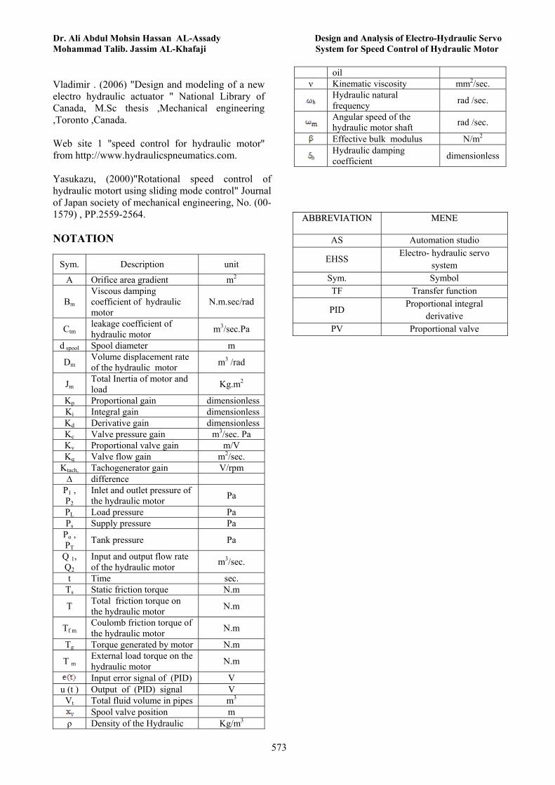
Vladimir . (2006) "Design and modeling of a new electro hydraulic actuator " National Library of Canada, M.Sc thesis ,Mechanical engineering ,Toronto ,Canada. Web site 1 ''speed control for hydraulic motor'' from http://www.hydraulicspneumatics.com. Yasukazu, (2000)"Rotational speed control of hydraulic motort using sliding mode control" Journal of Japan society of mechanical engineering, No. (00-1579) , PP.2559-2564. NOTATION
Sym. Description unit
A Orifice area gradient m2
Bm Viscous damping coefficient of hydraulic motor
N.m.sec/rad
Ctm leakage coefficient of hydraulic motor m3/sec.Pa
d spool Spool diameter m
Dm Volume displacement rate of the hydraulic motor m3 /rad
Jm Total Inertia of motor and load Kg.m2
Kp Proportional gain dimensionless Ki Integral gain dimensionless Kd Derivative gain dimensionless Kc Valve pressure gain m3/sec. Pa
Kv Proportional valve gain m/V Kq Valve flow gain m2/sec.
Ktach, Tachogenerator gain V/rpm ∆ difference
P1 , P2
Inlet and outlet pressure of the hydraulic motor Pa
PL Load pressure Pa Ps Supply pressure Pa
Po , PT
Tank pressure Pa
Q 1, Q2
Input and output flow rate of the hydraulic motor m3/sec.
t Time sec. Ts Static friction torque N.m
T Total friction torque on the hydraulic motor N.m
Tf m Coulomb friction torque of the hydraulic motor N.m
Tg Torque generated by motor N.m
T m External load torque on the hydraulic motor N.m
Input error signal of (PID) V u (t ) Output of (PID) signal V
Vt Total fluid volume in pipes m3 Spool valve position m
ρ Density of the Hydraulic Kg/m3
oil ν Kinematic viscosity mm2/sec.
h Hydraulic natural frequency rad /sec.
Angular speed of the hydraulic motor shaft rad /sec.
Effective bulk modulus N/m2
h Hydraulic damping coefficient dimensionless
AABBBBRREEVVIIAATTIIOONN MMEENNEE
AS Automation studio
EHSS Electro- hydraulic servo
system Sym. Symbol TF Transfer function
PID Proportional integral
derivative PV Proportional valve