design and analysis of naca4420 wind turbine …...design and analysis of naca4420 wind turbine...
TRANSCRIPT
http://www.iaeme.com/IJMET/index.asp 403 [email protected]
International Journal of Mechanical Engineering and Technology (IJMET) Volume 8, Issue 6, June 2017, pp. 403–410, Article ID: IJMET_08_06_042 Available online at http://www.iaeme.com/IJMET/issues.asp?JType=IJMET&VType=8&IType=6 ISSN Print: 0976-6340 and ISSN Online: 0976-6359 © IAEME Publication Scopus Indexed
DESIGN AND ANALYSIS OF NACA4420 WIND
TURBINE AEROFOIL USING CFD
S. Jebarose Juliyana
Assistant Professor, Department of Mechanical Engineering, Veltech Dr. RR & Dr.SR University, Chennai, India
Dr. J. Udaya Prakash
Associate Professor, Department of Mechanical Engineering, Veltech Dr. RR & Dr.SR University, Chennai, India
K. Karthik
Assistant Professor, Department of Mechanical Engineering, Veltech Dr. RR & Dr.SR University, Chennai, India
P. Pallavi
Assistant Professor, Department of Mechanical Engineering, Veltech Dr. RR & Dr.SR University, Chennai, India
M. Saleem
Assistant Professor, Department of Aeronautical Engineering, Veltech Dr. RR & Dr.SR University, Chennai, India
ABSTRACT
Researchers have worked on developing new kind of wind turbines to produce
power from wind energy. The rotational speed of the wind blades can be increased
due to steering aerofoil. The effect of turbulence plays a vital role on the performance
of the wind turbine. The purpose of this paper is to analyze the turbulent effect of wind
turbine aerofoil. The two dimensional model of NACA4420, aerofoil was created in
Solid Works. The blade with constant angle of attack was analyzed throughout the
length. This was done for angle of attack ranging from 3° to 10°. It was found that
blade with 4° angle of attack has the maximum L/D ratio. Finally the blades with
angle of attack 4° of NACA 4420 is analyzed at 4 sections from root to tip using
ANSYS CFD software. The purpose of the research is to improve the performance of
the wind turbine.
Key words: Wind Turbine, Aerofoils, Lift force, Drag force, Angle of attack. CFD.
Cite this Article: S. Jebarose Juliyana, Dr. J. Udaya Prakash, K. Karthik, P. Pallavi and M. Saleem. Design and Analysis of NACA4420 Wind Turbine Aerofoil using CFD. International Journal of Mechanical Engineering and Technology, 8(6), 2017, pp. 403–410. http://www.iaeme.com/IJMET/issues.asp?JType=IJMET&VType=8&IType=6

Design and Analysis of NACA4420 Wind Turbine Aerofoil using CFD
http://www.iaeme.com/IJMET/index.asp 404 [email protected]
1. INTRODUCTION
1.1. Wind Turbine
Wind possesses energy by virtue of its motion. Any device capable of slowing down the mass of moving air, like a sail or propeller, can extract part of the energy and convert it into useful work. The factors which determine the output from a wind energy converter are the wind speed, the cross – section of the windswept by the rotor and the overall conversion efficiency of the rotor, transmission system & generator or pump.
The wind turbine works on the principle of converting kinetic energy of wind to mechanical energy. Wind mills can be used to mill grains, lift water and to generate electricity. Our focus is on wind mills to generate electricity, these are called wind turbine generators. The parts of a horizontal axis Wind Turbine is shown in figure 1.
Figure 1 Parts of a Wind Turbine
1.2. Blade Profile
The aerofoil section nomenclature is given by National Advisory Committee on Aeronautics (NACA) as NACA 4 digit series, NACA 5 digit series, NACA 6 digit series etc. We have chosen NACA 4420 for this study. The significance of the four digits is,
4 – The maximum height of the camber line expressed as a percentage of the airfoil length (i.e.) 40 %.
4 – The horizontal location of the maximum camber line height in tenths of a chord length.
20 – The maximum thickness of the airfoil expressed as a percentage of the airfoil chord length. The blade specifications are given in Table 1.
S. Jebarose Juliyana, Dr. J. Udaya Prakash, K. Karthik, P. Pallavi and M. Saleem
http://www.iaeme.com/IJMET/index.asp 405 [email protected]
Table 1 Blade Specifications
Profile NACA 4420
Root chord length 1651mm
Tip chord length 650 mm
Length of blade 10700 mm
Hub diameter 337.5 mm
Hub length 1465 mm
Hub to blade(neck) 1475 mm
1.3. Lift and Drag Forces
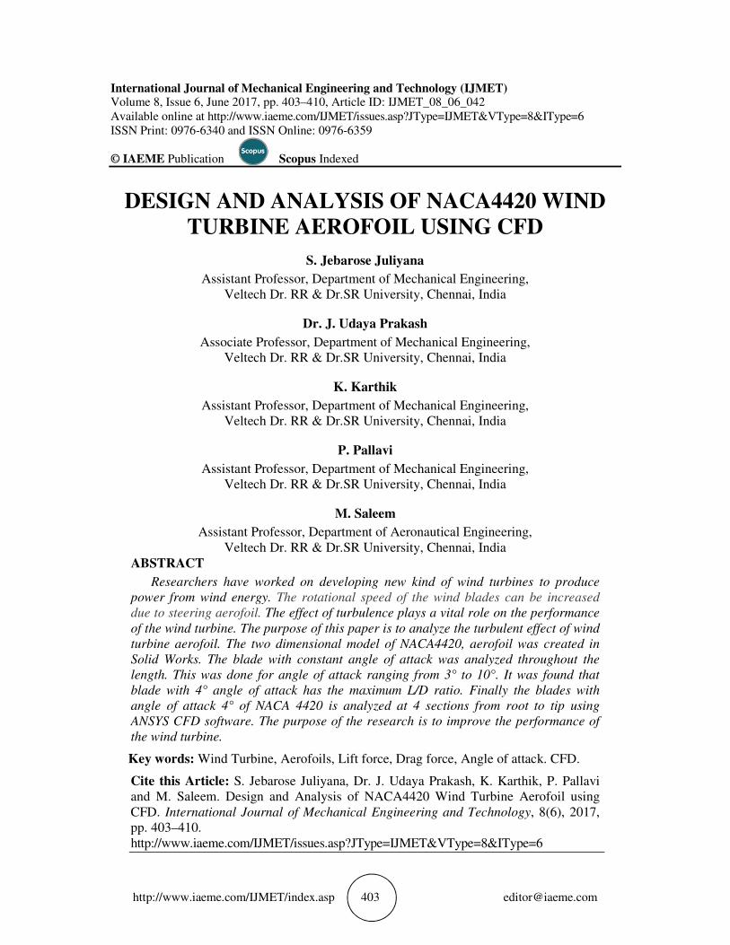
Lift on a body is defined as the force on the body in a direction normal to the flow direction. Lift will only present if the fluid incorporates a circulatory flow about the body such that which exists about a spinning cylinder. The velocity above the body is increased and so the static pressure is reduced. The velocity beneath is slowed down, giving an increase in static pressure. So, there is a normal force upwards called the lift force.
The drag on a body in an oncoming flow is defined as the force on the body in a direction parallel to the flow direction. For a windmill to operate efficiently the lift force should be high and drag force should be low. For small angles of attack, lift force is high and drag force is low. If the angles of attack (α) increases beyond a certain value, the lift force decreases and the drag force increases. So, the angle of attack plays a vital role. Lift and drag forces of a 2D aerofoil are shown in figure 2.
Figure 2 Lift and drag forces of a 2D aerofoil
2. LITERATURE REVIEW
Matt M. Hejazi, et al investigated on CFD analysis of a wind turbine blade, using splaret almaras, k −ω SST model for turbulent viscosity, in which, effect of dimensionless lift coefficient (CL),drag coefficient (CD) and pitching moment coefficient (Cm) at different angle of attack, was tested. For this test, a coupled solver and a turbulent viscosity model was utilized.
Parezanovic V & Rasuo B studied the simulations of few airfoils, which yielded results and are in good agreement with available wind tunnel measurements. In order to accurately simulate flow around airfoils at low Reynolds numbers as in cases investigated here, it is necessary to accurately simulate the effects of boundary level transition from laminar to turbulent conditions.
Connell, J. R et al investigated the wind turbines operate in the turbulent boundary layer of the atmosphere and due to the rotational sampling effect the blades experience a high level

Design and Analysis of NACA4420 Wind Turbine Aerofoil using CFD
http://www.iaeme.com/IJMET/index.asp 406 [email protected]
of turbulence. The effect of turbulence is investigated by large eddy simulations of the turbulent flow past a NACA airfoil at Reynolds number 1.6 million.
Spalart, P. R et al analyzed the Detached eddy simulation (DES) (hybrid of RANS) and large eddy simulation (LES). The effect of increasing the turbulence intensity and the results are compared to measurements from a wind tunnel. By including the inflow turbulence the agreement with measurements is improved for some angles of attack. The results indicate that the free stream turbulence may trigger separation of the flow at angles of attack close to stall.
Bertagnolio, F et al experimented an airfoil for a wind turbine blade the performance of the airfoil can typically be predicted by experiments and two-dimensional steady Reynolds Averaged Navier-Stokes (RANS) simulations. For low angles of attack RANS predicts the lift and drag with high accuracy because the flow is two-dimensional and steady
Tangler. J. L et al designed the Nine airfoil families that comprise 25 airfoils to address the unique performance characteristics of HAWTs. These blades are providing significant increases in annual energy production as a result of less sensitivity to roughness effects, better lift-to-drag ratios, and, in the case of stall-regulated rotors, through the use of more swept area for a given generator size. Because of the economic benefits provided by these airfoils, they are recommended for retrofit blades and most new wind turbine designs.
Jacobs et al studied two primary objectives re-evident from the design specifications for this airfoil. The first objective was to achieve a maximum lift coefficient that is relatively low (restrained). A requirement related to this objective was that the maximum lift coefficient not decreases with transition furred near the leading edge on both surfaces.
Mehrdad Ghods et al analyzed an aircraft, lift is caused by an upward force that is resulted from the difference in pressure between the top and the bottom surface of the wings. This difference in pressure is due to the special shape of the airfoil, and the amount of this lift is dependent upon the angle at which the wing is inclined. To find the maximum performance of the wing, it should be tested in a wind tunnel at different angles of attack. From testing the NACA 2415 it is determined that the optimum angle of attack is between 15-17 degrees.
3. MODELING AND DESIGN CALCULATION
The blade profile was chosen as NACA 4420. The profiles were obtained from Design Foil Workshop Software and were exported directly to Solid Works. The modeling was done in Solid Works and shown in figure 3.
Figure 3 Model of NACA 4420

S. Jebarose Juliyana, Dr. J. Udaya Prakash, K. Karthik, P. Pallavi and M. Saleem
http://www.iaeme.com/IJMET/index.asp 407 [email protected]
The L/D ratio for each angle of attack was calculated using design formulas and the graph for L/D ratio Vs Angle of Attack was shown in figure 4.
Figure 4 Angle of attack vs L/D Ratio
The maximum L/D ratio of 100.51 was obtained for an angle of attack of 4°. The ANSYS CFD analysis for angle of attack 4° was performed to identify the velocity and pressure distribution of NACA 4420 aerofoil for different sections of the wind mill blade.
4. CFD ANALYSIS OF AEROFOIL
The NACA 4420 profile from Design Foil Workshop software was exported to modeling software. The four sections are created at the blade from root to tip and shown in table 2.
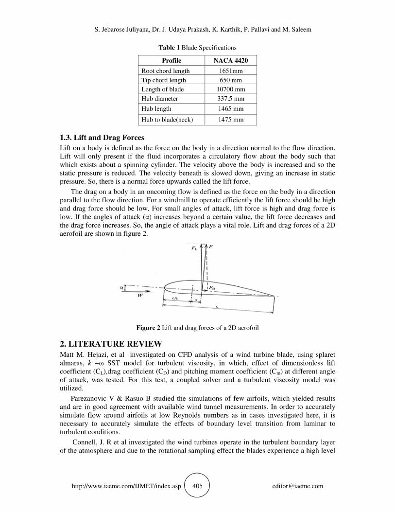
The aerofoil with wind area was generated in solid works, CFD analysis was done on ANSYS software. The aerofoil profile with wind area created in solid works was saved in IGES format, it was imported to ANSYS software. The analysis option was set as FLOTRON CFD. Fluid properties was set. The boundary condition was defined. Velocity was set as 12 m/sec and Pressure was set as zero at outlet of tunnel model. The velocity and pressure distribution of sections 1-4 are shown in figures 5-8 respectively.
Table 2 Chord Length at various sections
Section
Distance from hub
(m)
Chord length
(m)
1
2
3
4
2.95
5.275
8.375
10.7
1.651
1.348
0.9469
0.65
L/D ratio Vs AOA
0
20
40
60
80
100
120
3 6 912
15
18
AOA (IN DEG)
L/D
RA
TIO
L/D ratio
Design and Analysis of NACA4420 Wind Turbine Aerofoil using CFD
http://www.iaeme.com/IJMET/index.asp 408 [email protected]
Section -1
Figure 5 (a) Element plot (b) Velocity plot (c) Pressure plot
Section -2
Figure 6 (a) Velocity plot (b) Pressure plot
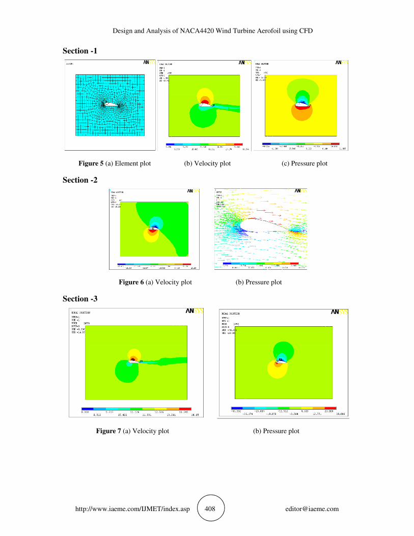
Section -3
Figure 7 (a) Velocity plot (b) Pressure plot

S. Jebarose Juliyana, Dr. J. Udaya Prakash, K. Karthik, P. Pallavi and M. Saleem
http://www.iaeme.com/IJMET/index.asp 409 [email protected]
Section -4
Figure 8 (a) Velocity plot (b) Pressure plot
5. CONCLUSIONS
The purpose of this analysis is to improve the performance of the wind turbine. The blade with constant angle of attack was analyzed throughout the length to find the blade with maximum L/D ratio. This was done for angle of attack ranging from 3° to 10° and found that blade with 4° angle of attack has the maximum L/D ratio. Finally the blade NACA 4420 with angle of attack 4° was analyzed at 4 sections from root to tip using ANSYS CFD software. The Velocity and pressure distribution were plotted. As a result, the angle of attack should be in the range of 3 to 4°, so that the maximum Lift to drag ratio can be obtained, which leads to increase in the efficiency.
REFERENCES
[1] Connell, J. R., “The Spectrum of Wind Speed Fluctuations Encountered by a Rotating Bladeof an Energy Conversion System,” Solar Energy, Vol 29, No5, pp. 363–375, 1982.
[2] Chang,Y.L, Yang S.L ,and Arici O, “Flow Field Computation of the NREL S809 Airfoil Using Various Turbulence Models,”ASME,EnergyWeek-96, Book VIII, vol. I-Wind Energy, pp 172-178, 1996.
[3] Bertagnolio.F, Sørensen.N and Johansen.J, “Profile Catalogue for Airfoil Sections Based on 3D Computations” Tech. Rep. Risø-R-1581(EN), RISØ National Laboratory, Roskilde, 2006.
[4] Tangler.J. L, National Renewable Energy Laboratory1617 Cole Boulevard, Golden, Colorado.
[5] Jacobs, Eastman N. Ward, Kenneth E. and Pinkerton The Characteristics of 78 Related Airfoil Sections from Tests in the Variable-Density Wind Tunnel. NACA Rep. 460, 1933.
[6] Baldwin,B, and Lomax.H, “Thin Layer Approximation and Algebraic Model for Separated Turbulent Flows,” AIAA-78-257. 1978.
[7] Asaf Varola, Cumali Ilkılıc.b, Yasin Varolc, Communications Faculty, Fırat University, Elazı&g, Turkey.
[8] Mehrdad Ghods, Technical Communication for Engineers, The University of British Columbia, July 23, 2001.

Design and Analysis of NACA4420 Wind Turbine Aerofoil using CFD
http://www.iaeme.com/IJMET/index.asp 410 [email protected]
[9] Jacobs, Eastman.N, “The Aerodynamic Characteristic of Eight Very Thick Airfoil from Tests in the Variable Density Wind Tunnel”. T. R. No. 391, 1931.
[10] W.A. Timmer An overview of NACA 6-digit airfoil series characteristics with reference to airfoils for large wind turbine blades. Delft University Wind Energy Research Institute.
[11] Naveen Janjanam, K. Raja Babu, S.S. Chowhan, Abid Khan, M. Teja, Comparison of NACA 23024 Aerofoil with and Without Vortex Generators Using CFD, International Journal of Mechanical Engineering and Technology, 8(5), 2017, pp. 556-566.
[12] Prof. V.B. Swami, Shubham Dhawale, Onkar More, Rohidas Gude, Suraj Rathod and Nikhil Kudave. Computational Fluid Dynamic Analysis of Airfoil NACA0015. International Journal of Mechanical Engineering and Technology, 8(2), 2017, pp. 210–219
[13] Mohamed Arif, Umar Rizwan, Vigneshwaran, Deebika Abhirami and Arun Kumar Synthetic Jet Flow Control for NACA 2412 Aerofoil. Journal of Mechanical Engineering and Technology, 8(5), 2017, pp. 843–850