design and analysis of suspension system for · pdf filedesign and analysis of suspension...
TRANSCRIPT
International Journal of Scientific & Engineering Research, Volume 7, Issue 3, March-2016 164 ISSN 2229-5518
IJSER © 2016 http://www.ijser.org
DESIGN AND ANALYSIS OF
SUSPENSION SYSTEM FOR AN ALL
TERRAIN VEHICLE Shijil P, Albin Vargheese, Aswin Devasia, Christin Joseph, Josin Jacob
Abstract—In this paper our work was to study
the static and dynamic parameter of the suspension system
of an ATV by determining and analyzing the dynamics of
the vehicle when driving on an off road racetrack. Though,
there are many parameters which affect the performance of
the ATV, the scope of this paper work is limited to
optimization, determination, design and analysis of
suspension systems and to integrate them into whole vehicle
systems for best results.
The goals were to identify and optimize the parameters
affecting the dynamic performance suspension systems
within limitations of time, equipment and data from
manufacturer.
In this paper we will also come across the following
aspects
a. Study the static and dynamic parameters of the
chassis.
b. Workout the parameters by analysis, design, and
optimization of suspension system.
c. Study of existing suspension systems and
parameters affecting its performance.
d. Determination of design parameters for
suspension system.
Index terms—All terrain vehicle, suspension, caster angle,
camber angle, toe angle, roll centre
1.INTRODUCTION
An All-Terrain Vehicle (ATV) is defined
by the American National Standards Institute
(ANSI) as a vehicle that travels on low pressure
tires, with a seat that is straddled by the operator,
along with handlebars for steering control. In some
vehicles steering wheel similar to passenger cars is
also used. As the name suggests, it is designed to
negotiate a wider variety of terrain than most other
vehicles. Although it is a street-legal vehicle in
some countries, it is not legal within most states
and provinces of Australia, the United States and
Canada and definitely not in India. By the current
ANSI definition, it is intended for use by a single
operator, although a change to include 2-seaters is
under consideration.
The All Terrain Vehicle (ATV) was
initially developed in the 1960‟s as a farmtown
vehicle in isolated, mountainous areas. During
spring thaws and rainy seasons, steep
IJSER

International Journal of Scientific & Engineering Research, Volume 7, Issue 3, March-2016 165 ISSN 2229-5518
IJSER © 2016 http://www.ijser.org
mountainous roads were often impassable with
conventional vehicles. It soon became a
recreational vehicle however, providing
transportation to areas inaccessible by other
motorized transport. Royal Enfield CO built and
put on sale a powered Quadra cycle in 1893 that
worked in the same way as, and resembles, a
modern quad-bike. ATVs were made in the United
States a decade before 3- and 4-wheeled vehicles
were introduced by Honda and other Japanese
companies. During the 1960s, numerous
manufacturers offered similar small off-road
vehicles that were designed to float and were
capable of traversing swamps, ponds and streams,
as well as dry land.
The early ATV‟s were mainly used for
agricultural purpose only. But now the definition
of ATV is changing. Many countries are allowing
ATVs as commercial vehicle, though with the
regulations on its use and safety. Now days, ATVs
are generally used in defense and sports
application redefining the ATV. Now the ATVs are
also coming with durable roll cages, added safety
of seat and shoulder belts and higher ground
clearance making it more rugged vehicle. The rear
cargo deck is more useful for hauling camping
gear, bales of hay, tools and supplies making it
suitable for exploring back country, riding sand
dunes, hunting, fishing and camping. ATVs Sport
models are built with performance, rather than
utility, in mind. To be successful at fast trail riding,
an ATV must have light weight, high power, good
suspension and a low center of gravity. These
machines can be modified for such racing
disciplines as motocross, woods racing, desert
racing, hill climbing, ice racing, speedway, tourist
trophy, flat track, drag racing and others.
1.2. Application of ATV’s
Initially the ATVs were solely used for the
transportation through the inaccessible areas, but
now these vehicles have found their application in
different areas as mentioned below:
a. In Defense Services like army and air force
etc to carry and transport guns, ammunition and
other supplies to remote areas of rough and varied
terrain.
b. By railways during construction of
railway tracks on mountain or on other rough
terrain.
c. By police force.
d. In sport also like golf for traveling one place to
other place.
e. In Antarctic bases for research things where use
of conventional vehicle is impossible.
f. Now a days ATVs are also used in adventuring
like mountaineering, in dirt and in snow.
1.3. Objective
The objective of our paper work was to
study the static and dynamic parameter of the
suspension system of an ATV by determining and
analyzing the dynamics of the vehicle when
driving on an off road racetrack. Though, there are
many parameters which affect the performance of
the ATV, the scope of this paper work is limited to
optimization, determination, design and analysis
IJSER

International Journal of Scientific & Engineering Research, Volume 7, Issue 3, March-2016 166 ISSN 2229-5518
IJSER © 2016 http://www.ijser.org
of suspension systems and to integrate them into
whole vehicle systems for best results.
The goals were to identify and optimize the
parameters affecting the dynamic performance
suspension systems within limitations of time,
equipment and data from manufacturer.
The objective of the paper includes:
e. Study the static and dynamic parameters
of the chassis.
f. Workout the parameters by analysis,
design,and optimization of suspension system.
g. Study of existing suspension systems and
parameters affecting its performance.
h. Determination of design parameters for
suspension system.
2. SUSPENSION SYSTEM
The suspension of vehicles needs to satisfy
a number of requirements which depend on
different operating conditions of the vehicle
(loaded/unloaded, acceleration/braking,
level/uneven road, straight running/ cornering).
Suspension systems serve a dual purpose
contributing to the vehicle's handling and braking
for good active safety and driving pleasure, and
keeping vehicle occupants comfortable and
reasonably well isolated from road noise, bumps,
and vibrations. The suspension also protects the
vehicle itself and mounted systems from damage
and wear.
Suspension is the term given to the system
comprise of springs, shock absorbers and linkages
that connects a vehicle to its wheels. The design of
front and rear suspension of a vehicle may be
different.
2.1. Basic Consideration for Suspension System
2.1.1. Vertical loading
When the road wheel comes across the
bump or a pit on the road it is subjected to vertical
forces (tensile or compressive) depending on the
load irregularity which are absorbed by the elastic
compression, shear, bending, twisting properties of
spring. To reduce the pitching tendency of the
vehicle, the front system should be less springing
than the rear suspension system.
2.1.2. Rolling
The center of gravity (C.G.) of the
vehicle is considerably above the ground. As a
result while taking turns the centrifugal force acts
outwards on the C.G. of vehicle, while the load
resistance acts inwards at the wheels. This give rise
to a couple turning the vehicle about the
longitudinal axis called rolling.
2.1.3. Brake dip and squat
On applying brakes the nose of the vehicle
dips which depends on the position of C.G.
relative to the ground, wheel base and other
suspension characteristics. This phenomenon is
called as dip. In the same way the torque loads
IJSER
International Journal of Scientific & Engineering Research, Volume 7, Issue 3, March-2016 167 ISSN 2229-5518
IJSER © 2016 http://www.ijser.org
during acceleration tend to lift the front of vehicle.
This effect is called as squat.
2.1.4. Side thrust
Centrifugal force during cornering,
crosswinds, cambering of the road causes side
thrust.
2.1.5. Road holding
The degree to which vehicle maintains the
contact with the road surface in various types of
directional changes as well as in straight line
motion is called as road holding.
2.1.6. Unsprung weight
Unsprung weight is the weight of the
vehicle components between suspension and road
surface (Rear axle assembly, steering knuckle, front
axle, wheels).
2.2. Types of Suspension System Used in Automobiles
Suspension systems can be broadly classified into
two subgroups – Dependent and Independent.
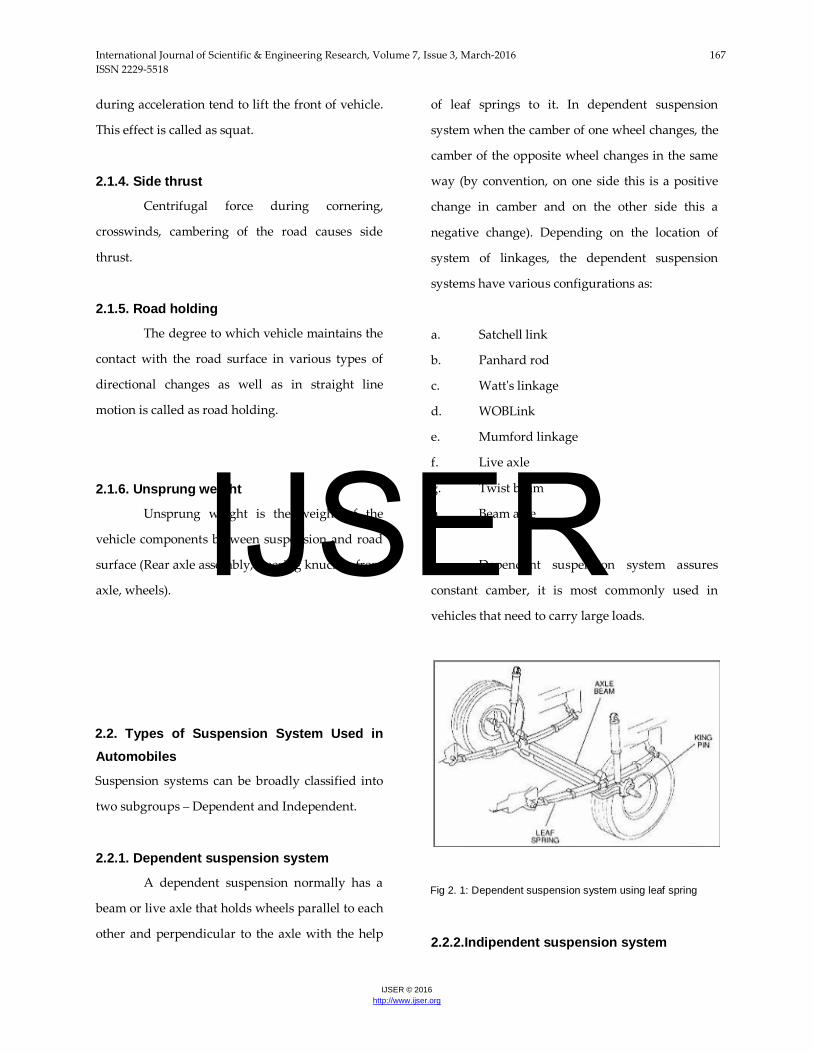
2.2.1. Dependent suspension system
A dependent suspension normally has a
beam or live axle that holds wheels parallel to each
other and perpendicular to the axle with the help
of leaf springs to it. In dependent suspension
system when the camber of one wheel changes, the
camber of the opposite wheel changes in the same
way (by convention, on one side this is a positive
change in camber and on the other side this a
negative change). Depending on the location of
system of linkages, the dependent suspension
systems have various configurations as:
a. Satchell link
b. Panhard rod
c. Watt's linkage
d. WOBLink
e. Mumford linkage
f. Live axle
g. Twist beam
h. Beam axle
Dependent suspension system assures
constant camber, it is most commonly used in
vehicles that need to carry large loads.
Fig 2. 1: Dependent suspension system using leaf spring
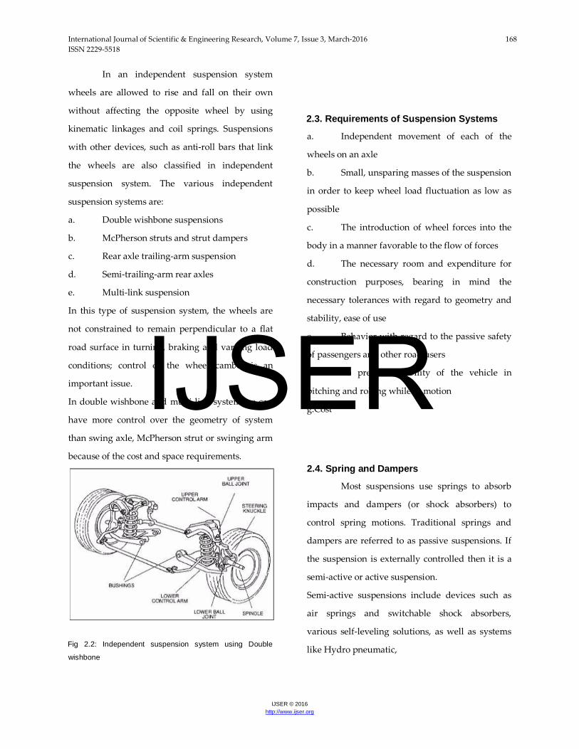
2.2.2.Indipendent suspension system
IJSER
International Journal of Scientific & Engineering Research, Volume 7, Issue 3, March-2016 168 ISSN 2229-5518
IJSER © 2016 http://www.ijser.org
In an independent suspension system
wheels are allowed to rise and fall on their own
without affecting the opposite wheel by using
kinematic linkages and coil springs. Suspensions
with other devices, such as anti-roll bars that link
the wheels are also classified in independent
suspension system. The various independent
suspension systems are:
a. Double wishbone suspensions
b. McPherson struts and strut dampers
c. Rear axle trailing-arm suspension
d. Semi-trailing-arm rear axles
e. Multi-link suspension
In this type of suspension system, the wheels are
not constrained to remain perpendicular to a flat
road surface in turning, braking and varying load
conditions; control of the wheel camber is an
important issue.
In double wishbone and multi-link system we can
have more control over the geometry of system
than swing axle, McPherson strut or swinging arm
because of the cost and space requirements.
Fig 2.2: Independent suspension system using Double
wishbone
2.3. Requirements of Suspension Systems
a. Independent movement of each of the
wheels on an axle
b. Small, unsparing masses of the suspension
in order to keep wheel load fluctuation as low as
possible
c. The introduction of wheel forces into the
body in a manner favorable to the flow of forces
d. The necessary room and expenditure for
construction purposes, bearing in mind the
necessary tolerances with regard to geometry and
stability, ease of use
e. Behavior with regard to the passive safety
of passengers and other road users
f. To preserve stability of the vehicle in
pitching and rolling while in motion
g.Cost
2.4. Spring and Dampers
Most suspensions use springs to absorb
impacts and dampers (or shock absorbers) to
control spring motions. Traditional springs and
dampers are referred to as passive suspensions. If
the suspension is externally controlled then it is a
semi-active or active suspension.
Semi-active suspensions include devices such as
air springs and switchable shock absorbers,
various self-leveling solutions, as well as systems
like Hydro pneumatic,
IJSER
International Journal of Scientific & Engineering Research, Volume 7, Issue 3, March-2016 169 ISSN 2229-5518
IJSER © 2016 http://www.ijser.org
Hydromantic, and Hydra gas suspensions.
Mitsubishi developed the world‟s first production
semi-active electronically controlled suspension
system in passenger cars; the system was first
incorporated in the 1987 Gallant model.
Fully active suspension systems use electronic
monitoring of vehicle conditions, coupled with the
means to impact vehicle suspension and behavior
in real time to directly control the motion of the
car.
With the help of control system, various semi-
active/active suspensions could realize an
improved design compromise among different
vibrations modes of the vehicle, namely bounce,
roll, pitch and warp modes. However, the
applications of these advanced suspensions are
constrained by the cost, packaging, weight,
reliability, and/or the other challenges.
Interconnected suspension, unlike semi-
active/active suspensions, could easily decouple
different vehicle vibration modes in a passive
manner. The interconnections can be realized by
various means, such as mechanical, hydraulic and
pneumatic. Anti-roll bars are one of the typical
examples of mechanical interconnections, while it
has been stated that fluidic interconnections offer
greater potential and flexibility in improving both
the stiffness and damping properties.
The leading / trailing swinging arm, fore-aft linked
suspension system together with inboard front
brakes had a much smaller unsprung weight than
existing coil spring or leaf designs. The
interconnection transmitted some of the force
deflecting a front wheel up over a bump, to push
the rear wheel down on the same side. When the
rear wheel met that bump a moment later, it did
the same in reverse, keeping the car level front to
rear.
The springing balance (which expresses
how well the front and rear axles are matched to
one another) also needs to be taken into
consideration. If a vehicle does not pitch when it
goes over bumps in the ground, but instead moves
up and down in parallel translation, it has a good
springing balance.
2.4.1. Spring rate
The spring rate (or suspension rate) is a
component in setting the vehicle's ride height or its
location in the suspension stroke. Vehicles which
carry heavy loads will often have heavier springs
to compensate for the additional weight that
would otherwise collapse a vehicle to the bottom
of its travel (stroke). Heavier springs are also used
in performance applications when the suspension
is constantly forced to the bottom of its stroke
causing a reduction in the useful amount of
suspension travel which may also lead to harsh
bottoming.
Springs that are too hard or too soft will
both effectively cause the vehicle to have no
suspension at all. Vehicles that commonly
experience suspension loads heavier than normal
have heavy or hard springs with a spring rate close
to the upper limit for that vehicle's weight. This
allows the vehicle to perform properly under a
heavy load when control is limited by the inertia of
IJSER
International Journal of Scientific & Engineering Research, Volume 7, Issue 3, March-2016 170 ISSN 2229-5518
IJSER © 2016 http://www.ijser.org
the load. Riding in an empty truck used for
carrying loads can be uncomfortable for
passengers because of its high spring rate relative
to the weight of the vehicle. A race car would also
be described as having heavy springs and would
also be uncomfortably bumpy. A luxury car, taxi,
or passenger bus would be described as having
soft springs. Vehicles with worn out or damaged
springs ride lower to the ground which reduces the
overall amount of compression available to the
suspension and increases the amount of body lean.
Performance vehicles can sometimes have spring
rate requirements other than vehicle weight and
load.
2.4.2. Mathematics of the spring rate
Spring rate is a ratio used to measure how
resistant a spring is to being
compressed or expanded during the spring's
deflection. The magnitude of the spring force
increases as deflection increases according to
Hooke's Law. Briefly, this can be stated as,
Where,
F is the force the spring exerts k is the spring rate of
the spring.
x is the displacement from equilibrium length i.e.
the length at which the spring is
neither compressed or stretched.
Spring rate is confined to a narrow interval by the
weight of the vehicle, the load the vehicle will
carry, and to a lesser extent by suspension
geometry and performance desires.
Spring rates typically have units of N/mm. A non-
linear spring rate is one for which the relation
between the spring's compression and the force
exerted cannot be fitted adequately to a linear
model. The spring rate of a coil spring may be
calculated by a simple algebraic equation or it may
be measured in a spring testing machine. The
spring constant k can be calculated as follows:
Where, d is the wire diameter, G is the spring's
shear modulus (e.g., about 80 GPa for steel), and N
is the number of wraps and D is the diameter of
the coil.
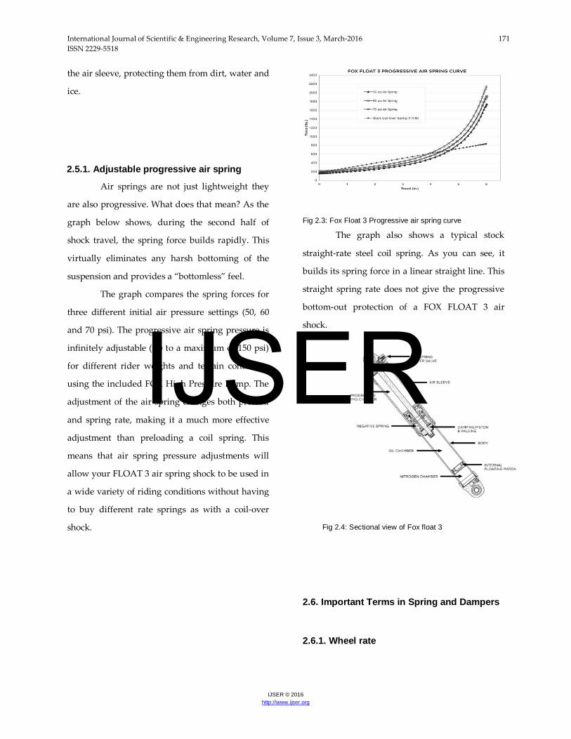
2.5 Fox Float 3 Air Shock
FOX FLOAT (FOX Load Optimizing Air
Technology) 3 air shocks are high-performance
shock absorbers that use air as springs, instead of
heavy steel coil springs or expensive titanium
coil springs. Underneath that air sleeve is a high-
performance, velocity-sensitive, shimmed
damping system. FLOAT 3 air shock dampers
contain high pressure nitrogen gas and FOX high
viscosity index shock oil separated by an Internal
Floating Piston system. This helps to ensure
consistent, fade-free damping in most riding
conditions
FLOAT 3 shocks are built using 6061-T6
aluminum for light weight and strength. The
chromed damper shaft is super-finished for low
friction and long seal life. All of the seals and
wipers are engineered specifically for FLOAT 3.
The damper shaft and seals are contained within
IJSER
International Journal of Scientific & Engineering Research, Volume 7, Issue 3, March-2016 171 ISSN 2229-5518
IJSER © 2016 http://www.ijser.org
the air sleeve, protecting them from dirt, water and
ice.
2.5.1. Adjustable progressive air spring
Air springs are not just lightweight they
are also progressive. What does that mean? As the
graph below shows, during the second half of
shock travel, the spring force builds rapidly. This
virtually eliminates any harsh bottoming of the
suspension and provides a “bottomless” feel.
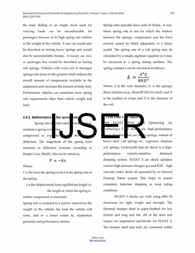
The graph compares the spring forces for
three different initial air pressure settings (50, 60
and 70 psi). The progressive air spring pressure is
infinitely adjustable (up to a maximum of 150 psi)
for different rider weights and terrain conditions
using the included FOX High Pressure Pump. The
adjustment of the air spring changes both preload
and spring rate, making it a much more effective
adjustment than preloading a coil spring. This
means that air spring pressure adjustments will
allow your FLOAT 3 air spring shock to be used in
a wide variety of riding conditions without having
to buy different rate springs as with a coil-over
shock.
Fig 2.3: Fox Float 3 Progressive air spring curve
The graph also shows a typical stock
straight-rate steel coil spring. As you can see, it
builds its spring force in a linear straight line. This
straight spring rate does not give the progressive
bottom-out protection of a FOX FLOAT 3 air
shock.
Fig 2.4: Sectional view of Fox float 3
2.6. Important Terms in Spring and Dampers
2.6.1. Wheel rate
IJSER

International Journal of Scientific & Engineering Research, Volume 7, Issue 3, March-2016 172 ISSN 2229-5518
IJSER © 2016 http://www.ijser.org
Wheel rate is the effective spring rate
when measured at the wheel. Wheel rate is usually
equal to or considerably less than the spring rate.
Commonly, springs are mounted on control arms,
swing arms or some other pivoting suspension
member. The wheel rate is calculated by taking the
square of the motion ratio times the spring rate.
Squaring the ratio is because the ratio has two
effects on the wheel rate. The ratio applies to both
the force and distance traveled.
Wheel rate on independent suspension is fairly
straight-forward. However, special consideration
must be taken with some non-independent
suspension designs. Yet because the wheels are
not independent, when viewed from the side
under acceleration or braking the pivot point is at
infinity (because both wheels have moved) and the
spring is directly in line with the wheel contact
patch. The result is often that the effective wheel
rate under cornering is different from what it is
under acceleration and braking. This variation in
wheel rate may be minimized by locating the
spring as close to the wheel as possible.
2.6.2. Roll couple percentage
Roll couple percentage is the effective
wheel rates, in roll, of each axle of the vehicle as a
ratio of the vehicle's total roll rate. Roll Couple
Percentage is critical in accurately balancing the
handling of a vehicle.
A vehicle with a roll couple percentage of
70% will transfer 70% of its sprung weight at the
front of the vehicle during cornering.
2.6.3. Weight transfer
Weight transfer during cornering,
acceleration or braking is usually calculated per
individual wheel and compared with the static
weights for the same wheels. Cornering wheel
weights requires knowing the static wheel weights
and adding or subtracting the unsprung, sprung
and jacking forces at each wheel.
2.6.4. Unsprung weight transfer
Unsprung weight transfer is calculated
based on the weight of the vehicle's components
that are not supported by the springs. This
includes tires, wheels, brakes, spindles, half the
control arm's weight and other components. These
components are then
(for calculation purposes) assumed to be connected
to a vehicle with zero sprung weight.
They are then put through the same
dynamic loads. The weight transfer for cornering
in the front would be equal to the total unsprung
front weight times the G-Force times the front
unsprung center of gravity height divided by the
front track width. The same is true for the rear.
2.6.5. Sprung weight trnsfer
Sprung Weight Transfer is the weight
transferred by only the weight of the vehicle
resting on the springs not the total vehicle weight.
IJSER
International Journal of Scientific & Engineering Research, Volume 7, Issue 3, March-2016 173 ISSN 2229-5518
IJSER © 2016 http://www.ijser.org
Calculating this requires knowing the vehicles
sprung weight (total weight less the unsprung
weight), the front and rear roll center heights and
the sprung center of gravity height (used to
calculate the roll moment arm length). Calculating
the front and rear sprung weight transfer will also
require knowing the roll couple percentage.
The roll axis is the line through the front and rear
roll centers that the vehicle rolls around during
cornering. The distance from this axis to the
sprung center of gravity height is the roll moment
arm length. The total sprung weight transfer is
equal to the Gforce times the sprung weight times
the roll moment arm length divided by the
effective track width. The front sprung weight
transfer is calculated by multiplying the roll couple
percentage times the total sprung weight transfer.
2.6.6. Jacking forces
Jacking forces can be thought of as the
centripetal force pushing diagonally upward from
the tire contact patch into the suspension roll
center. The front jacking force is calculated by
taking the front sprung weight times the G-force
times the front roll center height divided by the
front track width. The rear is calculated the same
way except at the rear.
2.6.7. Travel
Travel is the measure of distance from the
bottom of the suspension stroke to the top of the
suspension stroke. Bottoming or lifting a wheel can
cause serious control problems or directly cause
damage. "Bottoming" can be the suspension, tires,
fenders, etc. running out of space to move the body
or other components of the car hitting the road.
The control problems caused by lifting a wheel are
less severe if the wheel lifts when the spring
reaches its unloaded shape than they are if travel is
limited by contact of suspension members.
2.6.8. Damping
Damping is the control of motion or
oscillation, as seen with the use of hydraulic gates
and valves in a vehicles shock absorber. This may
also vary, intentionally or unintentionally. Like
spring rate, the optimal damping for comfort may
be less than for control.
Damping controls the travel speed and resistance
of the vehicles suspension. An undamped car will
oscillate up and down. With proper damping
levels, the car will settle back to a normal state in a
minimal amount of time. Most damping in modern
vehicles can be controlled by increasing or
decreasing the resistance to fluid flow in the shock
absorber.
2.6.9. Camber control
A tire wears and brakes best at -1 to -2
degrees of camber from vertical. Depending on the
tire, it may hold the road best at a slightly different
angle. Small changes in camber, front and rear, are
used to tune handling.
2.6.10. Roll center height
IJSER
International Journal of Scientific & Engineering Research, Volume 7, Issue 3, March-2016 174 ISSN 2229-5518
IJSER © 2016 http://www.ijser.org
This is important to body roll and to front
to rear roll moment distribution. However, the roll
moment distribution in most cars is set more by
the antiroll bars than the RCH. It may affect the
tendency to roll over.
2.6.11. Instant center
A tire's force vector points from the
contact patch of the tire through a point referred to
as the "instant center". This imaginary point is the
effective geometric point at which the suspension
force vectors are transmitted to the chassis.
Another way of looking at this is to imagine each
suspension control arm mounted only at the frame.
The axis that the arm rotates around creates an
imaginary line running through the vehicle.
Forces, as far as suspension geometry are
concerned, are transmitted either along this axis
(usually front to rear) or through this axis at a right
angle (usually right to left and intersects the ball
joint). When force lines of the upper and lower
control arms intersect, where they cross is the
Instant Center. The Instant Centers when viewed
from the front or side may not seem to have much
of a relation to each other until you imagine the
points in three dimensions. Sometimes the Instant
Center is at ground level or at a distant point due
to parallel control arms.
The instant center can also be thought of
as having the effect of converting multilink
suspension into a single control arm which pivots
at the Instant Center. This is only true at a given
suspension deflection, because an unequal length,
multi-link system has an instant center that moves
as the suspension is deflected.
2.6.12. Aanti-dive and anti-squat
Anti-dive and anti-squat are expressed in
terms of percentage and refer to the front diving
under braking and the rear squatting under
acceleration. They can be thought of as the
counterparts for braking and acceleration as
jacking forces are to cornering. The main reason for
the difference is due to the different design goals
between front and rear suspension, whereas
suspension is usually symmetrical between the left
and right of the vehicle.
Anti-dive and anti-squat percentage are
always calculated with respect to a vertical plane
that intersects the vehicle's center of gravity The
anti-dive is the ratio between the height of where
the tire force vector crosses the center of gravity
plane expressed as a percentage. An anti-dive ratio
of 50% would mean the force vector under braking
crosses half way between the ground and the
center of gravity. Anti-squat is the counterpart to
anti-dive and is for the rear suspension under
acceleration. Anti-dive and anti-squat may or may
not be desirable depending on the suspension
design.
2.6.13. Isolation from high frequency shock
For most purposes, the weight of the
suspension components is unimportant, but at
IJSER
International Journal of Scientific & Engineering Research, Volume 7, Issue 3, March-2016 175 ISSN 2229-5518
IJSER © 2016 http://www.ijser.org
high frequencies, caused by road surface
roughness, the parts isolated by rubber bushings
act as a multistage filter to suppress noise and
vibration better than can be done with only the
tires and springs.
2.6.14. Space occupied force distribution
Designs differ as to how much space they
take up and where it is located. It is generally
accepted that MacPherson struts are the most
compact arrangement for frontengine vehicles,
where the wheels is required to place the engine.
2.6.15. Air resistance (drag)
Certain modern vehicles have height
adjustable suspension in order to improve
aerodynamics and fuel efficiency. And modern
formula cars, that have exposed wheels and
suspension, typically use streamlined tubing rather
than simple round tubing for their suspension
arms to reduce drag. Also typical is the use of
rocker arm, push rod, or pull rod type suspensions,
that among other things, places the spring/damper
unit inboard and out of the air stream to further
reduce air resistance.
2.6.16. COST
Production methods improve, but cost is
always a factor. The continued use of the solid rear
axle, with unsprung differential, especially on
heavy vehicles, seems to be the most obvious
example.
2.7. Tires and Wheels
The tires are crucial functional elements
for the transmission of longitudinal, lateral and
vertical forces between the vehicle and road. The
tire properties should be as constant as possible
and hence predictable by the driver. As well as
their static and dynamic force transmission
properties, the requirements described below –
depending on the intended use of the vehicle – are
also to be satisfied.
Selecting the right tires for the ATV is not
difficult if we know what we are looking for, there
are some important things to consider in order to
make the best selection, doing a wrong selection
can kill the fuel economy, decrease performance
and possibly damage the vehicle.
Tread pattern is one of the most important
things to consider, there are several patterns like
mud tires, trail tires, sand tires and race tires. It is
needed to analyze first what type of terrain the
vehicle will drive in most, in order to select best
performing tires for that particular terrain. Since,
the ATV is meant to drive in all kinds of terrains,
an aggressive all terrain tires should be the best.
The all terrain tires come in two patterns,
flat and round. Flat tires have more treads to the
ground, and in the other hand round tires can
increase the vehicle speed. But the round tires also
IJSER
International Journal of Scientific & Engineering Research, Volume 7, Issue 3, March-2016 176 ISSN 2229-5518
IJSER © 2016 http://www.ijser.org
have a tendency to roll under during hard
cornering, while the flat tire "puts more rubber to
the track".
Then comes the problem with the choice
between the tall tire and the short tire, the a tall tire
will lift the ATV higher off the ground and give a
softer ride, but on the other hand a tall tire has
more sidewall flex which will give the ATV a
feeling of being loose during hard cornering.
Whereas a short tire gives more stability during
hard cornering and high speeds, but gives less
ground clearance and makes the ride a little
bumpier.
Things to remember while selecting ATV tires:
a. Ride Comfort: These tires ride
exceptionally smooth on pavement and dirt roads.
They also absorb the impact of rocks and other
obstacles very well. The driver should feel
comfortable and safe while driving the vehicle.
b. Steering/Handling: These tires steer
effortlessly and track well over the trail, but they
are a little sensitive to uneven surfaces, tending to
follow small ruts and grooves etc.
c. Puncture Resistance: Puncture resistance
should be very high as this vehicle is going to run
through rough terrains, water, mud and many
such adverse conditions. Also small bits of gravel
caught between the tire bead and rim should be
cleaned periodically as it causes to lose all air
minimizing life of the tire.
d. Mud Traction: Mud traction is as
expected, pretty good for a multi-purpose tire.
e. Sand/loose dirt track traction: This is
where these tires really shine, especially in very
steep terrain. The soft tread cleats that wrap
around the tire shoulders and flexible tire
construction combine to grab nicely on to most
dirt/rocky trail conditions i.e. it should have very
high sand tracks in order to deal with the muddy
tracks. [2, 6]
2.8. ELASTOKINEMATICS
„Elastokinematics‟ defines the alterations
in the position of the wheels caused by forces and
moments between the tires and the road or the
longitudinal movement of the wheel, against
suspension anchorage required to prevent
compliance, kinematics changes.
2.8.1. Wheel base
The wheelbase l, measured from the centre
of the front to the centre of the rear axle is an
important variable in the vehicle‟s ride and
handling properties.
The short body overhangs to the front and rear,
reduce the tendency to pitch oscillations and make
it possible to fit soft springing, normally associated
with a high level of ride comfort. A short
wheelbase, on the other hand, makes cornering
easier, i.e. gives a smaller swept turning circle for
the same steering input.
2.8.2. Track
IJSER
International Journal of Scientific & Engineering Research, Volume 7, Issue 3, March-2016 177 ISSN 2229-5518
IJSER © 2016 http://www.ijser.org
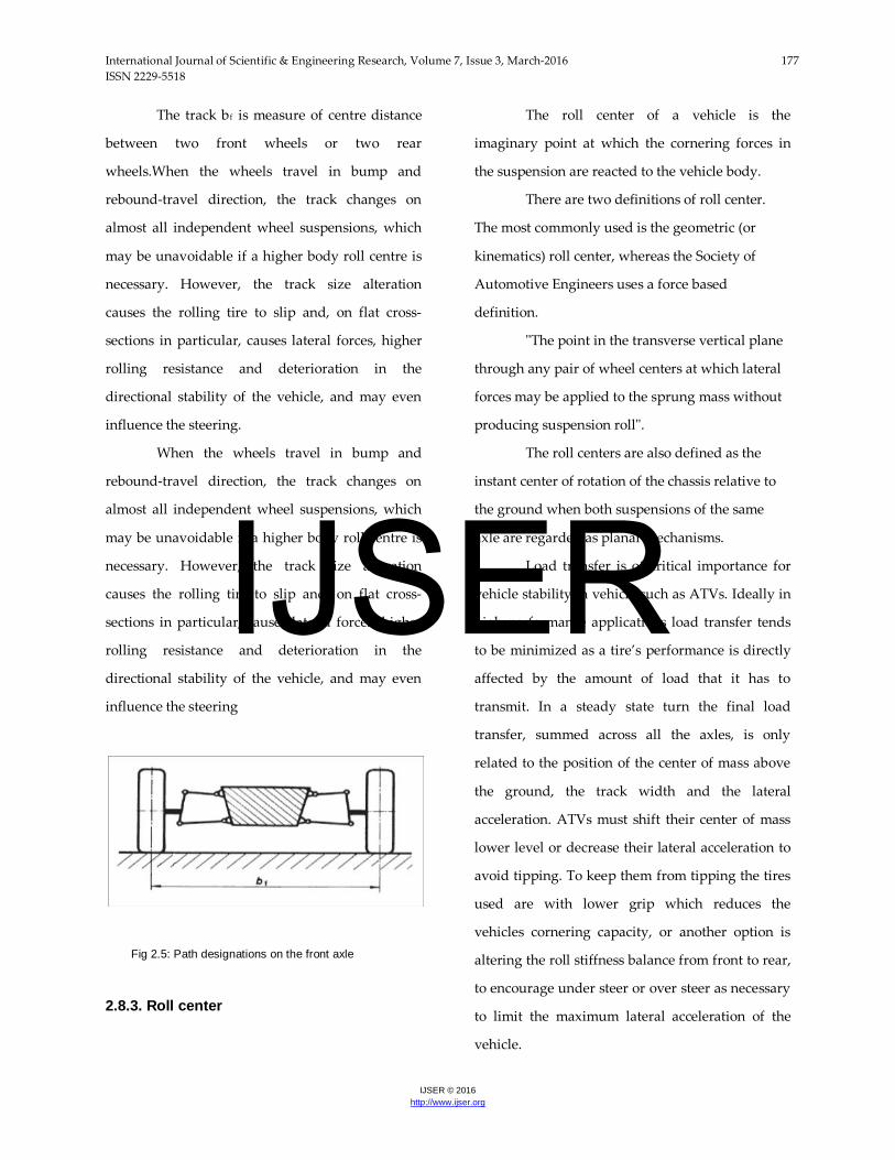
The track bf is measure of centre distance
between two front wheels or two rear
wheels.When the wheels travel in bump and
rebound-travel direction, the track changes on
almost all independent wheel suspensions, which
may be unavoidable if a higher body roll centre is
necessary. However, the track size alteration
causes the rolling tire to slip and, on flat cross-
sections in particular, causes lateral forces, higher
rolling resistance and deterioration in the
directional stability of the vehicle, and may even
influence the steering.
When the wheels travel in bump and
rebound-travel direction, the track changes on
almost all independent wheel suspensions, which
may be unavoidable if a higher body roll centre is
necessary. However, the track size alteration
causes the rolling tire to slip and, on flat cross-
sections in particular, causes lateral forces, higher
rolling resistance and deterioration in the
directional stability of the vehicle, and may even
influence the steering
Fig 2.5: Path designations on the front axle
2.8.3. Roll center
The roll center of a vehicle is the
imaginary point at which the cornering forces in
the suspension are reacted to the vehicle body.
There are two definitions of roll center.
The most commonly used is the geometric (or
kinematics) roll center, whereas the Society of
Automotive Engineers uses a force based
definition.
"The point in the transverse vertical plane
through any pair of wheel centers at which lateral
forces may be applied to the sprung mass without
producing suspension roll".
The roll centers are also defined as the
instant center of rotation of the chassis relative to
the ground when both suspensions of the same
axle are regarded as planar mechanisms.
Load transfer is of critical importance for
vehicle stability in vehicle such as ATVs. Ideally in
high performance applications load transfer tends
to be minimized as a tire’s performance is directly
affected by the amount of load that it has to
transmit. In a steady state turn the final load
transfer, summed across all the axles, is only
related to the position of the center of mass above
the ground, the track width and the lateral
acceleration. ATVs must shift their center of mass
lower level or decrease their lateral acceleration to
avoid tipping. To keep them from tipping the tires
used are with lower grip which reduces the
vehicles cornering capacity, or another option is
altering the roll stiffness balance from front to rear,
to encourage under steer or over steer as necessary
to limit the maximum lateral acceleration of the
vehicle.
IJSER

International Journal of Scientific & Engineering Research, Volume 7, Issue 3, March-2016 178 ISSN 2229-5518
IJSER © 2016 http://www.ijser.org
The geometric roll center of the vehicle can
be found by following basic geometrical
procedures when the vehicle is static. However,
when the vehicle rolls the roll centers migrate. The
rapid movement of roll centers when the system
experiences small displacements can lead to
stability problems with the vehicle. The roll center
height has been shown to affect behavior at the
initiation of turns such as nimbleness and initial
roll control.
2.8.3.1. Method of determining the roll center for double wishbone system
The height of the
(instantaneous centre of rotation) P determines the
position of the body roll centre Ro
From figure 2.6, the roll center height can
be calculated by formula,
Where,
As it can be seen in figure 2.6, for double
wishbone suspension only the position of the
control arms is important. The lines connecting the
inner and outer control arm pivots need to be
extended to fix virtual centre of rotation P and, at
the same time, its height p.
Fig 2. 6: Determination by drawing and calculation of the
paths hRo and p on double wishbone suspensions and a
multi-link as well as longitudinal transverse axes.
Fig 2. 7: Determination of the body roll centre on parallel
double wishbones; the virtual centre of rotation is at infinity.
P linked with the centre of tire contact W
gives the body roll centre Ro in the intersection
with the vehicle centre plane. In the case of parallel
control arms, P is at ∞ and a line parallel to them
needs to be drawn through W (Figure 2.7). Where
the virtual centre of rotation is a long way from the
wheel centre of contact, it is recommended that the
distances p and hRo be calculated using the
formulae listed above.
Steering control arm axes of rotation,
which are sloped when viewed from the side, need
E1 and G1 to be moved perpendicularly up or
down (Figure 2.8). The points E2 and G2 obtained
in this way – linked with E1 and G1 when viewed
IJSER
International Journal of Scientific & Engineering Research, Volume 7, Issue 3, March-2016 179 ISSN 2229-5518
IJSER © 2016 http://www.ijser.org
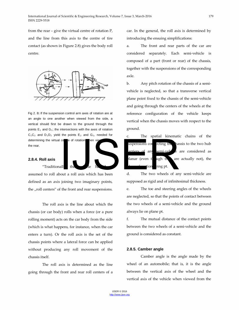
from the rear – give the virtual centre of rotation P,
and the line from this axis to the centre of tire
contact (as shown in Figure 2.8) gives the body roll
centre.
Fig 2. 8: If the suspension control arm axes of rotation are at
an angle to one another when viewed from the side, a
vertical should first be drawn to the ground through the
points E1 and G1; the intersections with the axes of rotation
C1C2 and D1D2 yield the points E2 and G2, needed for
determining the virtual centre of rotation when viewed from
the rear.
2.8.4. Roll axis
“Traditionally the vehicle has been
assumed to roll about a roll axis which has been
defined as an axis joining two imaginary points,
the „roll centers‟ of the front and rear suspensions.
The roll axis is the line about which the
chassis (or car body) rolls when a force (or a pure
rolling moment) acts on the car body from the side
(which is what happens, for instance, when the car
enters a turn). Or the roll axis is the set of the
chassis points where a lateral force can be applied
without producing any roll movement of the
chassis itself.
The roll axis is determined as the line
going through the front and rear roll centers of a
car. In the general, the roll axis is determined by
introducing the ensuing simplifications:
a. The front and rear parts of the car are
considered separately. Each semi-vehicle is
composed of a part (front or rear) of the chassis,
together with the suspensions of the corresponding
axle.
b. Any pitch rotation of the chassis of a semi-
vehicle is neglected, so that a transverse vertical
plane point fixed to the chassis of the semi-vehicle
and going through the centers of the wheels at the
reference configuration of the vehicle keeps
vertical when the chassis moves with respect to the
ground.
c. The spatial kinematic chains of the
suspensions connecting the chassis to the two hub
carriers of any semi-vehicle are considered as
planar (even though they are actually not), the
plane of motion being pt.
d. The two wheels of any semi-vehicle are
supposed as rigid and of infinitesimal thickness.
e. The toe and steering angles of the wheels
are neglected, so that the points of contact between
the two wheels of a semi-vehicle and the ground
always lie on plane pt.
f. The mutual distance of the contact points
between the two wheels of a semi-vehicle and the
ground is considered as constant.
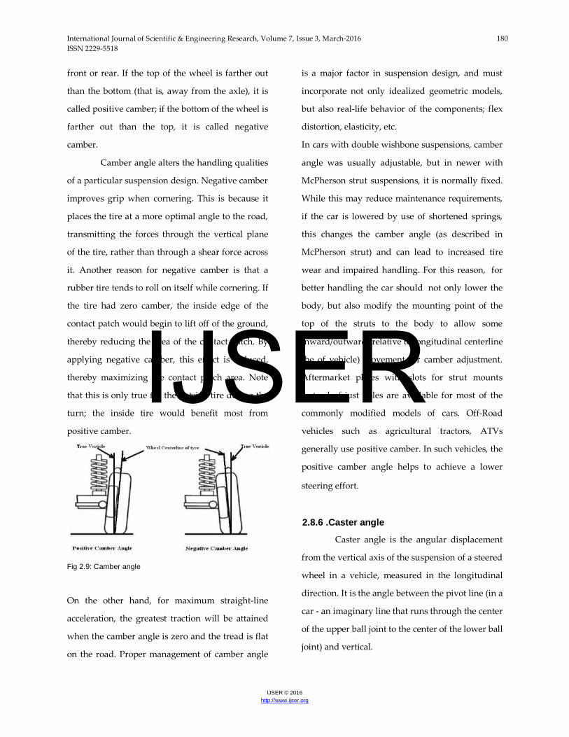
2.8.5. Camber angle
Camber angle is the angle made by the
wheel of an automobile; that is, it is the angle
between the vertical axis of the wheel and the
vertical axis of the vehicle when viewed from the
IJSER
International Journal of Scientific & Engineering Research, Volume 7, Issue 3, March-2016 180 ISSN 2229-5518
IJSER © 2016 http://www.ijser.org
front or rear. If the top of the wheel is farther out
than the bottom (that is, away from the axle), it is
called positive camber; if the bottom of the wheel is
farther out than the top, it is called negative
camber.
Camber angle alters the handling qualities
of a particular suspension design. Negative camber
improves grip when cornering. This is because it
places the tire at a more optimal angle to the road,
transmitting the forces through the vertical plane
of the tire, rather than through a shear force across
it. Another reason for negative camber is that a
rubber tire tends to roll on itself while cornering. If
the tire had zero camber, the inside edge of the
contact patch would begin to lift off of the ground,
thereby reducing the area of the contact patch. By
applying negative camber, this effect is reduced,
thereby maximizing the contact patch area. Note
that this is only true for the outside tire during the
turn; the inside tire would benefit most from
positive camber.
Fig 2.9: Camber angle
On the other hand, for maximum straight-line
acceleration, the greatest traction will be attained
when the camber angle is zero and the tread is flat
on the road. Proper management of camber angle
is a major factor in suspension design, and must
incorporate not only idealized geometric models,
but also real-life behavior of the components; flex
distortion, elasticity, etc.
In cars with double wishbone suspensions, camber
angle was usually adjustable, but in newer with
McPherson strut suspensions, it is normally fixed.
While this may reduce maintenance requirements,
if the car is lowered by use of shortened springs,
this changes the camber angle (as described in
McPherson strut) and can lead to increased tire
wear and impaired handling. For this reason, for
better handling the car should not only lower the
body, but also modify the mounting point of the
top of the struts to the body to allow some
inward/outward (relative to longitudinal centerline
the of vehicle) movement for camber adjustment.
Aftermarket plates with slots for strut mounts
instead of just holes are available for most of the
commonly modified models of cars. Off-Road
vehicles such as agricultural tractors, ATVs
generally use positive camber. In such vehicles, the
positive camber angle helps to achieve a lower
steering effort.
2.8.6 .Caster angle
Caster angle is the angular displacement
from the vertical axis of the suspension of a steered
wheel in a vehicle, measured in the longitudinal
direction. It is the angle between the pivot line (in a
car - an imaginary line that runs through the center
of the upper ball joint to the center of the lower ball
joint) and vertical.
IJSER
International Journal of Scientific & Engineering Research, Volume 7, Issue 3, March-2016 181 ISSN 2229-5518
IJSER © 2016 http://www.ijser.org
Fig 2.10: caster angle
As shows in figure, caster angle is angle
between center plane of wheel (AA) and line
joining two pivot points E and G.
The pivot points of the steering are angled such
that a line drawn through them intersects the road
surface slightly ahead of the contact point of the
wheel. The purpose of this is to provide a degree of
self-centering for the steering - the wheel casters
around so as to trail behind the axis of steering.
This makes a car easier to drive and improves its
directional stability (reducing its tendency to
wander). Excessive caster angle will make the
steering heavier and less responsive, although, in
racing, large caster angles are used to improve
camber gain in cornering. Caster angles over 10
degrees with radial tires are common. Power
steering is usually necessary to overcome the
jacking effect from the high caster angle.
The steering axis (the dotted line in the
diagram above) does not have to pass through the
center of the wheel, so the caster can be set
independently of the mechanical trail, which is the
distance between where the steering axis hits the
ground, in side view, and the point directly below
the axle. The interaction between caster angle and
trail is complex, but roughly speaking they both
aid steering, caster tends to add damping, while
trail adds 'feel', and return ability. In the extreme
case the system is undamped but stable, as the
wheel oscillates around the 'correct' path.
Complicating this still further is that the lateral
forces at the tire do not act at the center of the
contact patch, but at a distance behind the nominal
contact patch. This distance is called the pneumatic
trail and varies with speed, load, steer angle,
surface, tire type, tire pressure and time. A good
starting point for this is 30 mm behind the nominal
contact patch.
2.8.7. Kingpin inclination and kingpin offset at ground
According to ISO 8855, the kingpin
inclination is the angle ζ which arises between the
steering axis EG and a vertical to the road (Figure
2.11). The kingpin offset is the horizontal distance
rζ from the steering axis to the intersecting point of
line N‟N in the wheel centre plane with the road.
Larger kingpin inclination angles are
necessary to give the vehicle a small or negative
kingpin offset. In commercial vehicles, tractors and
building-site Lorries, the inclination of the kingpin
is often equivalent to the angle ζ, whereas the
wheels are controlled by ball joints on the front
axles of passenger cars. On double wishbone
suspensions, the steering axis therefore goes
through the centers of the ball sockets E and G
indicated; the engineering detail drawing must
show the total angle of camber and kingpin
inclination.
IJSER
International Journal of Scientific & Engineering Research, Volume 7, Issue 3, March-2016 182 ISSN 2229-5518
IJSER © 2016 http://www.ijser.org
The McPherson strut and strut damper
have a greater effective distance between the lower
ball joint G and the upper mounting point E in the
wheel house; however, the upper axle parts are
next to the wheel, so attention should be paid to
creating enough clearance for the rotating tire
(possibly for snow chains). As a result, a higher
inclination of the steering axis and a higher angle ζ
has to be accepted. In addition, as can be seen in
the illustrations, point G has been shifted to the
wheel to obtain a negative kingpin offset. The
steering axis then no longer matches the centre line
of the suspension strut. Due to the relationship
between camber and kingpin inclination shown in
Figure 2.11, the angle ζ does not need to be
tolerance on double wishbone suspensions.
Fig 2. 11: The Kingpin Inclination and Kingpin offset
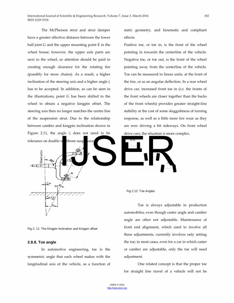
2.8.8. Toe angle
In automotive engineering, toe is the
symmetric angle that each wheel makes with the
longitudinal axis of the vehicle, as a function of
static geometry, and kinematic and compliant
effects.
Positive toe, or toe in, is the front of the wheel
pointing in towards the centerline of the vehicle.
Negative toe, or toe out, is the front of the wheel
pointing away from the centerline of the vehicle.
Toe can be measured in linear units, at the front of
the tire, or as an angular deflection. In a rear wheel
drive car, increased front toe in (i.e. the fronts of
the front wheels are closer together than the backs
of the front wheels) provides greater straight-line
stability at the cost of some sluggishness of turning
response, as well as a little more tire wear as they
are now driving a bit sideways. On front wheel
drive cars, the situation is more complex.
Fig 2.12: Toe Angles
Toe is always adjustable in production
automobiles, even though caster angle and camber
angle are often not adjustable. Maintenance of
front end alignment, which used to involve all
three adjustments, currently involves only setting
the toe; in most cases, even for a car in which caster
or camber are adjustable, only the toe will need
adjustment.
One related concept is that the proper toe
for straight line travel of a vehicle will not be
IJSER
International Journal of Scientific & Engineering Research, Volume 7, Issue 3, March-2016 183 ISSN 2229-5518
IJSER © 2016 http://www.ijser.org
correct while turning, since the inside wheel must
travel around a smaller radius than the outside
wheel; to compensate for this, the steering linkage
typically conforms more or less to Ackermann
steering geometry, modified to suit the
characteristics of the individual vehicle.
Individuals who decide to adjust their car's static
ride height, either by raising or lowering the
springs, should have the car properly aligned. The
common misconception is that camber angle
causes an increased rate of tire wear, when in fact
its contribution to tire wear is usually only visible
over the entire life of the tire.
3.DESIGN
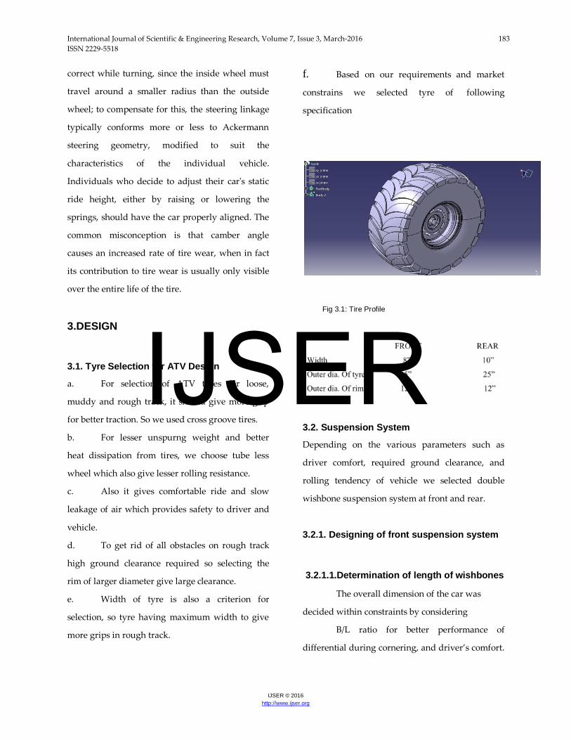
3.1. Tyre Selection for ATV Design
a. For selection of ATV tyres for loose,
muddy and rough track, it should give more grip
for better traction. So we used cross groove tires.
b. For lesser unspurng weight and better
heat dissipation from tires, we choose tube less
wheel which also give lesser rolling resistance.
c. Also it gives comfortable ride and slow
leakage of air which provides safety to driver and
vehicle.
d. To get rid of all obstacles on rough track
high ground clearance required so selecting the
rim of larger diameter give large clearance.
e. Width of tyre is also a criterion for
selection, so tyre having maximum width to give
more grips in rough track.
f. Based on our requirements and market
constrains we selected tyre of following
specification
Fig 3.1: Tire Profile
3.2. Suspension System
Depending on the various parameters such as
driver comfort, required ground clearance, and
rolling tendency of vehicle we selected double
wishbone suspension system at front and rear.
3.2.1. Designing of front suspension system
3.2.1.1.Determination of length of wishbones
The overall dimension of the car was
decided within constraints by considering
B/L ratio for better performance of
differential during cornering, and driver’s comfort.
IJSER
International Journal of Scientific & Engineering Research, Volume 7, Issue 3, March-2016 184 ISSN 2229-5518
IJSER © 2016 http://www.ijser.org
From this we have decided track width as52” at
front and 50” at rear and wheel Base as 57”.
According to the required travel for front
suspension system of around 8” we have decided
to go for Double wishbone system which gives
maximum travel amongst all suspension systems.
The double wishbone system is more flexible and
provides better ride comfort on bumpy terrain;
also it is easy to manufacture. Moreover we get
more control on parameters of suspension
geometry.
We have decided the optimum length of
wishbone keeping in mind the required leg space
at front, the required ground clearance and the
angles at which wishbones were positioned. The
values of angles for wishbones were determined
by required roll center height at front. To achieve
that, we have fixed the feasible range for the height
of roll center. Generally for the stability of vehicle
it is required that the height of roll center at front is
around 10.12” and at rear is9.44” for a ground
clearance of 12” front and 11” rear. This roll center
positioning provides better transmission of forces
acting on the vehicle along the roll axis which
yields good stability of vehicle and increased effect
of roll/yaw damping. Then we selected the
horizontal distance between roll center and
instantaneous center as 53.22”.The position of
instantaneous center which is more near to infinity
is best suitable for a stable suspension design. To
get a positive scrub radius of 2.6” we fixed kingpin
inclination (steering axis inclination) as 10º.
The parameters which is initially fixed for
drawing front suspension geometry for obtaining
the optimum length of wishbone are given below.
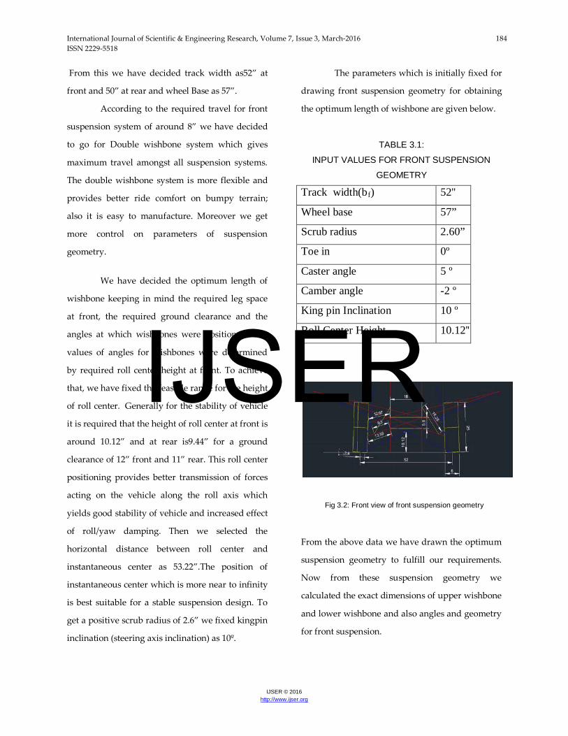
TABLE 3.1:
INPUT VALUES FOR FRONT SUSPENSION
GEOMETRY
Track width(bf) 52''
Wheel base 57”
Scrub radius 2.60”
Toe in 0º
Caster angle 5 º
Camber angle -2 º
King pin Inclination 10 º
Roll Center Height 10.12''
Fig 3.2: Front view of front suspension geometry
From the above data we have drawn the optimum
suspension geometry to fulfill our requirements.
Now from these suspension geometry we
calculated the exact dimensions of upper wishbone
and lower wishbone and also angles and geometry
for front suspension.
IJSER

International Journal of Scientific & Engineering Research, Volume 7, Issue 3, March-2016 185 ISSN 2229-5518
IJSER © 2016 http://www.ijser.org
TABLE 3.2: FINAL VALUES OBTAINED FOR DESIGNING
FRONT WISHBONE
Length of upper wish bones 12.07"
Length of lower wish bones 13.59''
Inclination of wishbone with upper
horizondal(α)
12O
Inclination of wishbone with lower
horizontal(β)
17O
3.2.1.2. Calculation of spring
Most automotive suspension systems use
helical springs. Next step in suspension designing
is to get dimensions of helical spring. Depending
on wishbone travel the spring and damper travel
was determined. Mounting of spring to lower
wishbones give better suspension effect.
Spring stiffness for front suspension can
be calculated by
Spring stiffness = 4×3.142×1.22×205×.56252
=20.72 N/mm
Here we decided to use fox float 3 air
shock of following specification which comes in
the range of our stiffness value and load of vehicle
TABLE 3.3:
SPECIFICATION OF FOX SHOCK USED IN
FRONT
Part Length Travel Comp
830-12-301 16.2 4.5 11.5
3.2.2. Designing of rear suspension system 3.2.2.1 Determination of length of wishbones
Here we initialy fix a rollcenter height of
9.44” and distance between the roll center and
instantaneous center is taken as 44.58”
TABLE 3.4:
INPUT VALUES FOR REAR
Track width(bf) 50''
Toe in 0o
Roll Center Height 9.44”
suspension geometry
Fig 3.3: Front view of rear suspension geometry
IJSER
International Journal of Scientific & Engineering Research, Volume 7, Issue 3, March-2016 186 ISSN 2229-5518
IJSER © 2016 http://www.ijser.org
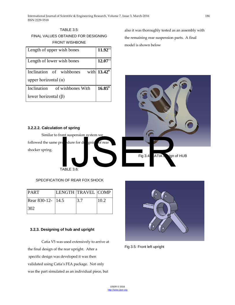
TABLE 3.5: FINAL VALUES OBTAINED FOR DESIGNING
FRONT WISHBONE
Length of upper wish bones 11.92''
Length of lower wish bones 12.07''
Inclination of wishbones with
upper horizontal (α)
13.42o
Inclination of wishbones With
lower horizontal (β)
16.85o
3.2.2.2. Calculation of spring
Similar to front suspension system we
followed the same procedure for designing of rear
shocker spring.
TABLE 3.6:
SPECIFICATION OF REAR FOX SHOCK
PART LENGTH TRAVEL COMP
Rear 830-12-
302
14.5 3.7 10.2
3.2.3. Designing of hub and upright
Catia V5 was used extensively to arrive at
the final design of the rear upright. After a
specific design was developed it was then
validated using Catia’s FEA package. Not only
was the part simulated as an individual piece, but
also it was thoroughly tested as an assembly with
the remaining rear suspension parts. A final
model is shown below
Fig 3.4: CATIA design of HUB
Fig 3.5: Front left upright
IJSER
International Journal of Scientific & Engineering Research, Volume 7, Issue 3, March-2016 187 ISSN 2229-5518
IJSER © 2016 http://www.ijser.org
Fig 3.6: Rear left upright
4.ANALYSIS
Testing analysis was done twice during
the project time line; prior to fabrication and after
fabrication, on the track. The various parts of the
vehicle were modeled on the simulation software
first in order to get the proper idea of its assembly,
fabrication and possible difficulties in fabrication.
Another and most important advantage of the
modeling was to check for any possibility of the
failure of the component. The modeling software
provided us with the information of the stress
distribution in the component or in the system and
its behavior under static and dynamic loading
conditions. This has saved lot of redesign work as
well as it reduced the overall cost of vehicle.
For software modeling and analysis we have
utilized CATIA software. The results of these
analyses are explained further in this chapter.
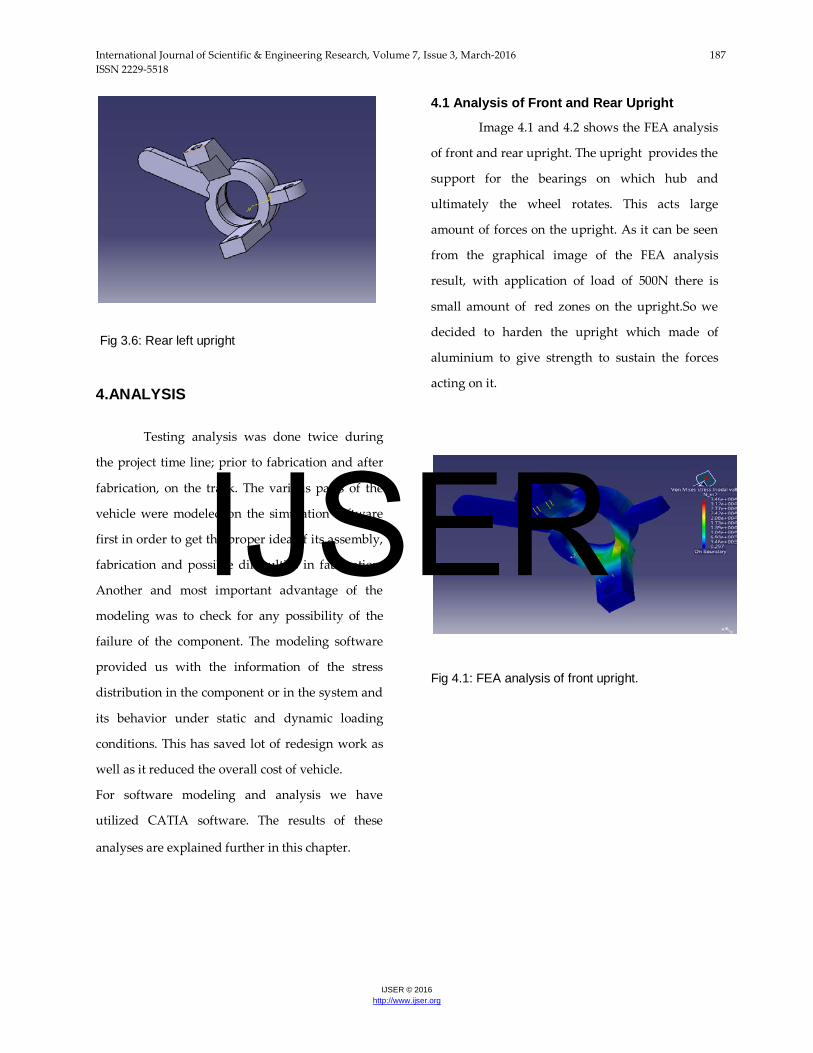
4.1 Analysis of Front and Rear Upright
Image 4.1 and 4.2 shows the FEA analysis
of front and rear upright. The upright provides the
support for the bearings on which hub and
ultimately the wheel rotates. This acts large
amount of forces on the upright. As it can be seen
from the graphical image of the FEA analysis
result, with application of load of 500N there is
small amount of red zones on the upright.So we
decided to harden the upright which made of
aluminium to give strength to sustain the forces
acting on it.
Fig 4.1: FEA analysis of front upright.
IJSER
International Journal of Scientific & Engineering Research, Volume 7, Issue 3, March-2016 188 ISSN 2229-5518
IJSER © 2016 http://www.ijser.org
Fig 4.2: FEA analysis of rear s upright
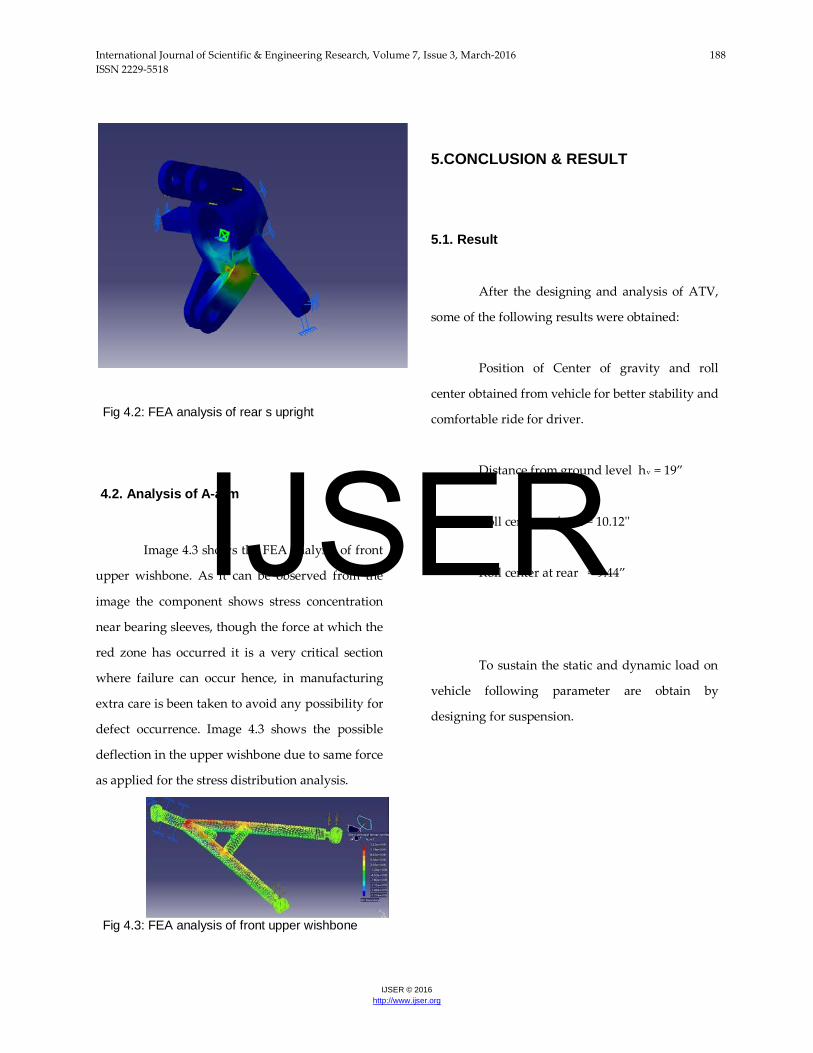
4.2. Analysis of A-arm
Image 4.3 shows the FEA analysis of front
upper wishbone. As it can be observed from the
image the component shows stress concentration
near bearing sleeves, though the force at which the
red zone has occurred it is a very critical section
where failure can occur hence, in manufacturing
extra care is been taken to avoid any possibility for
defect occurrence. Image 4.3 shows the possible
deflection in the upper wishbone due to same force
as applied for the stress distribution analysis.
Fig 4.3: FEA analysis of front upper wishbone
5.CONCLUSION & RESULT
5.1. Result
After the designing and analysis of ATV,
some of the following results were obtained:
Position of Center of gravity and roll
center obtained from vehicle for better stability and
comfortable ride for driver.
Distance from ground level hv = 19”
Roll center at front = 10.12''
Roll center at rear = 9.44”
To sustain the static and dynamic load on
vehicle following parameter are obtain by
designing for suspension.
IJSER
International Journal of Scientific & Engineering Research, Volume 7, Issue 3, March-2016 189 ISSN 2229-5518
IJSER © 2016 http://www.ijser.org
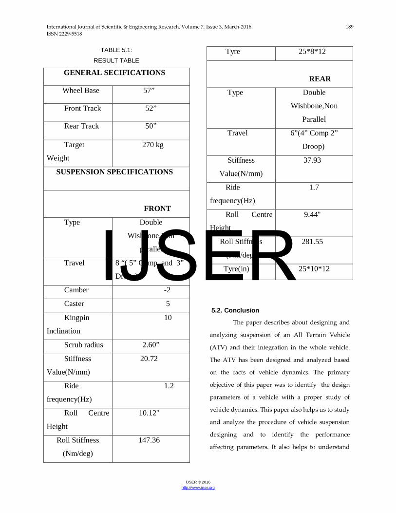
TABLE 5.1: RESULT TABLE
GENERAL SECIFICATIONS
Wheel Base 57”
Front Track 52”
Rear Track 50”
Target
Weight
270 kg
SUSPENSION SPECIFICATIONS
FRONT
Type Double
Wishbone,Non
parallel
Travel 8 “( 5” Comp. and 3”
Droop)
Camber -2
Caster 5
Kingpin
Inclination
10
Scrub radius 2.60”
Stiffness
Value(N/mm)
20.72
Ride
frequency(Hz)
1.2
Roll Centre
Height
10.12''
Roll Stiffness
(Nm/deg)
147.36
Tyre 25*8*12
REAR
Type Double
Wishbone,Non
Parallel
Travel 6”(4” Comp 2”
Droop)
Stiffness
Value(N/mm)
37.93
Ride
frequency(Hz)
1.7
Roll Centre
Height
9.44''
Roll Stiffness
(Nm/deg)
281.55
Tyre(in) 25*10*12
5.2. Conclusion
The paper describes about designing and
analyzing suspension of an All Terrain Vehicle
(ATV) and their integration in the whole vehicle.
The ATV has been designed and analyzed based
on the facts of vehicle dynamics. The primary
objective of this paper was to identify the design
parameters of a vehicle with a proper study of
vehicle dynamics. This paper also helps us to study
and analyze the procedure of vehicle suspension
designing and to identify the performance
affecting parameters. It also helps to understand
IJSER
International Journal of Scientific & Engineering Research, Volume 7, Issue 3, March-2016 190 ISSN 2229-5518
IJSER © 2016 http://www.ijser.org
and overcome the theoretical difficulties of vehicle
design.
REFERENCES • Kim, H. S., Hwang, Y. S., Yoon, H. S., ” Dynamic
Stress Analysis of a BusSystems”, Proceedings of 2nd MSC worldwide automotive conference, MSC,2000. http://www.mscsoftware.com/support/library/conf/auto00/p03200.pdf
• Fermer, M., McInally, G., Sandin, G., “Fatigue Life Analysis of Volvo S80Bi-fuel”, Proceedings of 1st MSC worldwide automotive conference,MSC, 1999http://www.mscsoftware.com/support/library/conf/auto99/p00499.pdf
• Johansson, I., and Gustavsson, M., “FE-based Vehicle Analysis of HeavyTrucks Part I” Proceedings of 2nd MSC worldwide automotive conference,MSC, 2000 www.mscsoftware.com/support/library/conf/auto00/p01200.pdf
• Oijer, F., “FE-based Vehicle Analysis of Heavy Trucks Part II”, Proceedings of 2nd MSC worldwide automotive conference, MSC, 2000www.mscsoftware.com/support/library/conf/auto00/p01100.pdf
• Parnell, T., White, C., and Day, S., “Finite Element Simulation of 1800 Rollover for Heavy Truck Vehicles”, ASCE Engineering mechanicconference, Baltimore, 1999. http://citeseer.ist.psu.edu/407030.html
• Chiba, S., Aoyama K., Yanabu, K., Tachibana, H.,
Matsuda, K., Uchikura, M., “Fatigue Strength Prediction of Truck Cab by CAE”, Journal ofMitsubishi Motors TechnicalReview, Vol.15, 2003, pp. 54-60.
• Lee, D. C., Choi, H. S., Han, C. S., “Design of Automotive Body structure Using Multicriteria Optimization” , Journal of Structural and Multidisciplinary Optimization, Vol. 32, 2006, pp. 161-167.http://www.springerlink.com/content/y70812k267632r47/
• Jin-yi-min, “Analysis and Evaluation of Minivan Body Structure” , Proceedings of 2nd MSC worldwide automotive conference, MSC, 2000.http://www.mscsoftware.com/suppot/lbrary/conf/auto00/p00500.pdf
• Lee, J. N., Nikravesh, P. E., “Steady State Analysis ofMultibody Systems with Reference to Vehicle Dynamics” , Journal ofNonlinear Dynamics, Vol. 5, 1994, pp. 181- 192.http://www.springerlink.com/content/jwu5842568731t84
• Thomas D. Gillespie; Fundamental of Vehicle Dynamics; ISBN: 978-1- 56091-199-9; February 1992.
• John C. Dixon; Suspension analysis and computation geometry; ISBN: 978-0-470-51021-6; October 2009
• Prof. Dr. Georg Rill “Vehicle Dynamics”, Lecture Notes, November 2002.
IJSER