design and evaluation of an mri-compatible linear motion
TRANSCRIPT

Western University Western University
Scholarship@Western Scholarship@Western
Medical Biophysics Publications Medical Biophysics Department
1-1-2016
Design and evaluation of an MRI-compatible linear motion stage. Design and evaluation of an MRI-compatible linear motion stage.
Mohammad Ali Tavallaei
Patricia M Johnson
Junmin Liu
Maria Drangova
Follow this and additional works at: https://ir.lib.uwo.ca/biophysicspub
Part of the Medical Biophysics Commons
Citation of this paper: Citation of this paper: Tavallaei, Mohammad Ali; Johnson, Patricia M; Liu, Junmin; and Drangova, Maria, "Design and evaluation of an MRI-compatible linear motion stage." (2016). Medical Biophysics Publications. 91. https://ir.lib.uwo.ca/biophysicspub/91

Preprint of Med Phys. 2016 Jan;43(1):62. doi: 10.1118/1.4937780.
Design and Evaluation of an MRI-Compatible Linear Motion Stage
Mohammad Ali Tavallaei, PhD,1, 2* Patricia M. Johnson, BSc,1,3 Junmin Liu, PhD,1 and Maria
Drangova, PhD1,2,3
1Imaging Research Laboratories, Robarts Research Institute, The University of Western Ontario,
London, Ontario, Canada 2Biomedical Engineering Graduate Program, The University of Western Ontario, London,
Ontario, Canada 3Department of Medical Biophysics, Schulich School of Medicine & Dentistry, The University
of Western Ontario, London, Ontario, Canada
*Correspondence to: Mohammad Ali Tavallaei, Imaging Research Laboratories, Robarts
Research Institute, 1151 Richmond St, London, Ontario N6A 5B7, Canada.
Phone: (519) 931-5777 ext. 24064. Fax: (519) 931-5260. E-mail: [email protected]

Abstract:
Purpose
To develop and evaluate a tool for accurate, reproducible and programmable motion control of
imaging phantoms for use in motion sensitive MRI applications. 5
Methods
In this paper we introduce a compact linear motion stage that is made of non-magnetic material
and is actuated with an Ultrasonic motor. The stage can be positioned at arbitrary positions and
orientations inside the scanner bore to move, push, or pull arbitrary phantoms. Using optical
trackers, measuring microscopes and navigators the accuracy of the stage in motion control was 10
evaluated. Also, the effect of the stage on image SNR, artifacts and B0 field homogeneity was
evaluated.
Results
The error of the stage in reaching fixed positions was 0.025±0.021 mm. In execution of dynamic
motion profiles the worst-case normalized root mean squared error was below 7% (for 15
frequencies below 0.33Hz). Experiments demonstrated that the stage did not introduce artifacts,
nor did it degrade the image SNR. The effect of the stage on the B0 field was less than 2 ppm.
Conclusion
The results of the experiments indicate the proposed system is MRI compatible and can create
reliable and reproducible motion that may be used for validation and assessment of motion 20
related MRI applications.
KEYWORDS: Motion, MRI-guided therapy, Multimodality imaging, Tracking, Quality
assessment, MRI compatibility
1. INTRODUCTION 25
Anatomical motion in patients is ubiquitous, varies temporally, and is patient specific. Magnetic resonance imaging (MRI) is highly sensitive to motion1, 2 and developments have been made to both reduce its effects on image quality (ghost artifacts, blurring, and reduction of SNR)3-10 as well as to extract physiological information (flow measurement, elastography, strain and deformation analysis, etc.).11-14 In addition to the need for motion correction for improved 30 MR imaging, the recent incorporation of MRI in hybrid imaging systems (e.g. PET-MRI) has increased interest in using MRI to improve PET image quality (though motion compensation).15-
18 Furthermore, MRI-guided radiotherapy is also being investigated as it provides an opportunity to monitor and correct for motion19-23 which impedes accurate targeting and delivery of therapy.19, 24 35
In the development and validation stages of motion measurement and correction techniques it is important to be able to simulate physiological motion within the MRI scanner, for example for studies developing respiratory motion correction techniques.25-27 Several motion phantoms have been described in the literature, addressing the need to move objects within the scanner with a known profile and reproducibly. These motion phantoms actuate motion in one of 40 two ways: using non-MRI-compatible DC or stepper motors that must be placed at the end of long actuating rods,20, 28-32 or incorporating pneumatic actuators that generally lack accurate positioning and motion control.33, 34 Recent research on pneumatic actuator design, has resulted in the development pneumatic step motors 35-37 that allow for more accurate control, however, the performance of these motors is dependent on the length of the pneumatic hoses between the 45 distributor and the motor. Furthermore, these options are not yet commercially available. Further challenges associated with the above mentioned motion phantoms include their size and weight, lack of versatility to move arbitrary phantoms in varying orientations and execution of arbitrary motion profiles.
Many of these limitations can be addressed through the use piezoelectric based actuators. 50 Piezoelectric actuators have been used extensively for MRI applications and have been shown to be MRI compatible. Various types of MRI compatible piezoelectric based actuators have been developed, and have been used in MRI guided therapeutic applications38-40 (e.g. positioning of Ultrasound transducers). Among the various options for piezoelectric actuators the most common types that are commercially available are the linear actuators (e.g. piezo LEGS linear, 55 PiezoMotor, Sweden; HR series, Nanomotion Ltd., Israel), and the rotary actuators (e.g. piezo LEGS rotary, PiezoMotor, Sweden). Among the rotary piezoelectric based motors, travelling wave rotary ultrasonic motors (USM) have an unlimited range of motion and generally provide a high torque output. Therefore, they are an attractive option for applications that have a high torque/force requirement. However, a challenge in controlling these high-torque travelling wave 60 USMs has been that they have a nonlinear, time-variant and temperature dependent dynamic response. Recent developments by our group41, 42 have allowed for dynamic robust motion control of these motors that overcomes the limitation mentioned above. In the proposed control scheme, a robust inverse dynamic control approach is used to ensure accurate motion control, over prolonged periods, despite temperature dependent and time varying motor dynamics. 65
To the best knowledge of the authors, no fully MRI-compatible positioning systems have been developed – with demonstrated validation – for generation of dynamic, accurate and reproducible motion control of conventional phantoms, during MR imaging, and for prolonged periods. Therefore, using a USM and a linear motion stage made of nonmagnetic materials we have developed an MRI compatible motion stage that can move any user-selected phantom to a 70

defined position or dynamically move the phantom to follow a user-defined motion profile. In this paper, the stage’s accuracy in executing dynamic motion profiles – in both laboratory settings and inside the scanner during imaging – is quantified. Furthermore, to test its MRI compatibility, the effect of the stage on image artifacts, SNR and B0 homogeneity is evaluated. The use of the stage is evaluated with different pulse sequences and an example application of 75 the stage used with gated imaging is provided.
2. METHODS
2.A. System design and set up Figure 1 is a schematic of the 80
design used for the linear motion stage. While the general design is straight forward, ensuring MRI compatibility demands the use of non-magnetic materials. An 8-start, 2.54 cm travel-per-85 turn lead screw was custom fabricated from Polyether ether ketone (PEEK) to drive a Polyoxymethylene (Delrin) carriage along rails made of Polytetrafluoroethylene (Teflon). All 90 materials were selected for their mechanical properties, while ensuring MRI compatibility. The dimensions of the stage were selected to enable a range of motion of up to 5 cm, while maintaining the device small (13 x 7 x 29 cm overall dimensions) so that it can be as versatile as possible and fit within a variety of scanner/RF coil configurations. Note that the range of travel was selected to ensure that the stage is capable of replicating motion typically experienced in 95 clinical applications, particularly those associated with respiratory motion43. However it must be added that incorporating a longer lead screw can extend the range of travel.
The actuator of the stage is an ultrasonic motor (USR60-NM, Fukoku-Shinsei, Japan), selected for its MRI compatibility, power and torque specifications. To drive the 100 USM motor, the commercially available drive circuitry (D2060, Shinsei-Fukoku, Japan) was used. This driver unit has a user controllable analogue input voltage that allows for adjustment of the motor’s 105 speed; the unit also allows for changing of the motor direction by adjusting two binary inputs. To control the motor motion dynamically, a custom designed embedded system had to be developed to supply the 110 driver circuitry with the appropriate control signal. This control system captures the motor’s position by decrypting the signals from a quadrature incremental optical encoder (with 1000 pulses per revolution) that is connected to the motor shaft. The controller then calculates the error in 115
Fig. 1. Schematic diagram of the stage. An ultrasonic motor (UMS) is used to drive a carriage mounted on a lead screw.
Fig. 2. The MRI compatible motion stage shown as it would be set up within the MRI scanner. The controller is positioned in the control room and the connections are passed through low pass filters installed within the RF shield of the scanner room.

position control by comparing the motor’s measured position to that of the reference. The measured error is used to calculate and update the control signal such that the error converges to zero. This calculated control signal is then fed to the motor’s driver circuitry. The details of the controller design and its hardware implementation are thoroughly described in.41, 42
The control unit was programmed to enable three different modes of operation: 1) 120 translation to a user-defined position, 2) sinusoidal motion with user-defined amplitude and frequency, and 3) execution of a user-defined motion profiles (e.g. one that mimics respiratory motion). Interface with the control unit is achieved either through its display panel or through a serial port. In order to facilitate use with gated applications, the control unit was programmed to output a 5 V pulse once per cycle for the sinusoidal profiles and at arbitrary times for user-125 specified dynamic motion profiles.
In a typical setup, the control unit is positioned in the scanner control room while the stage is placed within the scanner bore, as illustrated in Fig. 2. To minimize the introduction of external electromagnetic interference into the magnet room and to obtain undistorted feedback from the motor encoder, the electrical connections for the motor and the encoder signals were 130 passed through low pass capacitive filters (1000 pF) with a 3 MHz cutoff frequency (CONN67, Ramsey Electronics, USA), mounted on the penetration panel of the scanner room’s RF shield.
2.B. Evaluation in the laboratory setting Stage performance was evaluated both in the laboratory setting and within the MRI
scanner. In the laboratory, the accuracy of the motion stage was evaluated for both fixed 135 positions and dynamic reference profiles. For all laboratory tests the stage was loaded with a weight of 3 kg. The accuracy of the stage in reaching fixed reference positions was evaluated using an optical measuring microscope (STM6, Olympus, Japan). The carriage was taken to its home position (arbitrarily defined at the center of the stage) using the controller and this position was defined on the microscope as the origin for future measurements. Reference positions of ±1, 140 ±5, ±10 and ±20 mm were prescribed and repeated 10 times for each direction. After each motion was executed the carriage position was measured using the microscope and the USM encoder (logged through the control unit).
To evaluate the execution of dynamic motion, an optical tracking tool was attached to the carriage and sinusoidal reference profiles, with amplitudes of 2, 5, 7 and 10 mm at frequencies of 145 1, 0.5, 0.33, 0.25 and 0.2 Hz, were prescribed. The position of the tracking tool was measured using an optical tracker (Vicra, Northern Digital Inc., Canada) and logged at 20 Hz for a period of 5 minutes; the USM encoder logged the carriage motion simultaneously. For each motion profile, individual cycles were superimposed and the absolute error and root-mean-squared errors from the prescribed profile were calculated using MATLAB (MathWorks, USA). In each case 150 normalized root-mean-squared error (NRMSE) was calculated by dividing the RMSE by the amplitude of the prescribed sine wave.
Finally, the ability of the motion stage to execute physiological motion profiles was tested. The respiratory motion profile recorded from a patient over 45 seconds was programmed into the controller (10 ms intervals) and executed over a period of 5 minutes. The motion profile 155 was generated from a marker block (Varian Real-time Position Management System) with two infrared markers placed on the patient's surface between the xyphoid process and umbilicus. For the optical experiments, the profile was used without scaling. The executed profiles, as measured by the optical tracker, were compared to the programmed profile.
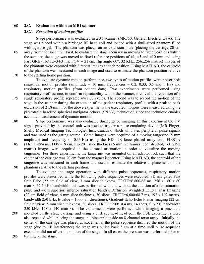
2.C. Evaluation within an MRI scanner 160 2.C.1 Execution of motion profiles
Stage performance was evaluated in a 3T scanner (MR750, General Electric, USA). The stage was placed within a birdcage RF head coil and loaded with a skull-sized phantom filled with agarose gel. The phantom was placed on an extension plate (placing the carriage 20 cm away from the isocentre. First, to evaluate the stage accuracy in moving to fixed positions within 165 the scanner, the stage was moved to fixed reference positions of ±1, ±5 and ±10 mm and using Fast GRE (TR/TE=34/3 ms, FOV = 21 cm, flip angle 60°, 32 KHz, 256x256 matrix) images of the phantom were captured with 3 repeat images at each position. Using MATLAB, the centroid of the phantom was measured in each image and used to estimate the phantom position relative to the starting home position. 170
To evaluate dynamic motion performance, two types of motion profiles were prescribed: sinusoidal motion profiles (amplitude = 10 mm; frequencies = 0.2, 0.33, 0.5 and 1 Hz) and respiratory motion profiles (from patient data). Two experiments were performed using respiratory profiles: one, to confirm repeatability within the scanner, involved the repetition of a single respiratory profile repeated over 60 cycles. The second was to record the motion of the 175 stage in the scanner during the execution of the patient respiratory profile, with a peak-to-peak excursion of 21.8 mm. For the above experiments the executed motions were measured using the pre-rotated baseline spherical navigator echoes (SNAV) technique,3 since the technique enables accurate measurement of dynamic motion.
Stage performance was also evaluated during gated imaging. In this experiment the 5 V 180 signal provided by the control unit was used to trigger a pulse-emulating device (MR Finger, Shelly Medical Imaging Technologies Inc., Canada), which simulates peripheral pulse signals and was used as the gating source. Gated images were acquired of a moving tangerine (5 mm amplitude and frequency of 0.33 Hz) using the HD T/R knee phased array coil; FIESTA (TR/TE=8/4 ms, FOV=19 cm, flip 20°, slice thickness 5 mm, 25 frames reconstructed, 160 x192 185 matrix) images were acquired in the coronal orientation in order to visualize the moving tangerine. For these experiments, the tangerine was mounted on an adaptor rod, such that the center of the carriage was 20 cm from the magnet isocenter. Using MATLAB, the centroid of the tangerine was measured in each frame and used to estimate the relative displacement of the phantom relative to the starting position. 190
To evaluate the stage operation with different pulse sequences, respiratory motion profiles were prescribed while the following pulse sequences were executed: 3D navigated Fast Spin Echo (22 cm field of view, 3 mm slice thickness, TR/TE=6,800/68 ms, 256 x 160 x 60 matrix, 62.5 kHz bandwidth; this was performed with and without the addition of a fat saturation pulse and 4-cm superior/ inferior saturation bands); Diffusion Weighted Echo Planar Imaging 195 (22 cm field of view, 4 mm slice thickness, 30 slices, TR/TE=6,600/68.7 ms, 192 x 192 matrix, bandwidth 250 kHz, b-value = 1000, all directions); Gradient-Echo Echo Planar Imaging (22 cm field of view, 5 mm slice thickness, 30 slices, TR/TE=200/10.4 ms, 14 shots, flip 90°, bandwidth 250 kHz ,128 x 140 matrix). The experiments were performed while imaging a pineapple mounted on the stage carriage and using a birdcage head head coil; the FSE experiments were 200 also repeated while placing the stage and pineapple inside an 8-channel torso array. Initially the center of the carriage was placed at isocenter; if the pulse sequence disabled the motion of the stage (due to RF interference) the stage was pulled back 5 cm at a time until pulse sequence execution did not affect the motion of the stage. In all cases the pre-scan was performed prior to turning on the stage. 205

2.C.2 Evaluation of the effect of the stage on image artifact level, field homogeneity, noise
Despite the use of MRI-compatible materials for fabricating the stage, it was important to determine whether the stage operation introduced image artifacts, additional noise, or significant magnetic field homogeneity degradation. First, image artifacts were quantified following the methods outlined in the ASTM standard for the evaluation of MR image artifacts from passive 210 implants.44 Specifically, the motion stage was placed on the patient bed beneath a Nylon support structure on which a 33 X 22 X 13 cm water based phantom (CTL rectangular, model 2406200; General Electric, Milwaukee, WI) was placed. The body RF coil was used to acquire axial spin echo (SE) (TR/TE=800/10 ms, FOV = 24 cm, 32 KHz, 256x160 matrix) and gradient recalled echo (GRE) (TR/TE=500/20 ms, FOV = 24 cm, flip angle 60°, 32 KHz, 256x160 matrix) 215 images. In each case, ten 5-mm thick slices centered over the carriage were acquired. In accordance with the ASTM guidelines, the acquisitions were repeated with flipped phase encode and readout directions. The motion stage was then removed – without moving the phantom – and the four acquisitions were repeated. Following ASTM guidelines, the corresponding slices of each sequence were compared between the two conditions (stage present or absent); a change in 220 intensity of over 30% at any pixel was considered as artifact and represented as a binary image.44
The same experimental set-up was used to evaluate the effect of the stage on main magnetic field (B0) homogeneity. Images of the phantom were acquired with and without the motion stage, using a 3-echo GRE pulse sequence (3D IDEAL, TR/TE=7/3ms, FOV/slice thickness = 32 cm /2 cm, acquisition matrix = 156 X 156 X 156); when the stage was present the 225 system was on and the motor and carriage were stationary. B0 field maps were calculated using the B0-NICE technique45 for each condition and the difference between the two B0 maps was calculated to represent the inhomogeneity induced by the presence of the stage.
Lastly, the guidelines of the National Electrical Manufacturer’s Association (NEMA) for the measurement of signal-to-noise ratio (SNR) in MR images were followed to evaluate the 230 effect of the stage on image SNR.46 Spin echo images (FOV 24 cm, slice thickness 6 mm, TR/TE= 1,300/20 ms, 256 × 256 matrix, and BW 15.6 kHz) were acquired of a 17-cm-diameter water phantom doped gadolinium-based contrast agent (MRS HD sphere, model 2152220; General Electric, Milwaukee, WI; T1/T2 = 392/297 ms). For SNR evaluation, two sets of images were obtained: one with the stage on and moving beneath the phantom and the other with the 235 stage removed and disconnected. The scanner’s gain settings were preserved between the two acquisitions. These experiments were performed at a room temperature of 20 °C.
3. RESULTS 3.A. Accuracy in the laboratory setting
The mean absolute error of the system in taking the stage to fixed positions, measured 240 with the microscope, was 0.025±0.021 mm. The measured mean error, indicating bias in the system, was 0.017±0.028 mm. The measurement results of the sinusoidal motion profiles are presented in Fig. 3, where each subplot represents an overlay of the measured positions of all cycles tracked for 5 minutes. The worst-case normalized root mean squared error (NRMSE) was below 7% for frequencies below 0.33 Hz and better than 10% for frequencies below 0.5 Hz. A 245 sample sinusoidal profile (0.5 Hz, 7 mm amplitude) is shown in Fig. 4a with the corresponding 95% confidence interval; Fig. 4b illustrates the corresponding power spectrum for the reference and measured profiles. Figure 4c depicts the results of the respiratory profile measurements, demonstrating that the motion stage is able to reproduce physiological motion profiles, with a confidence interval similar to that reported for the sinusoidal profiles. 250
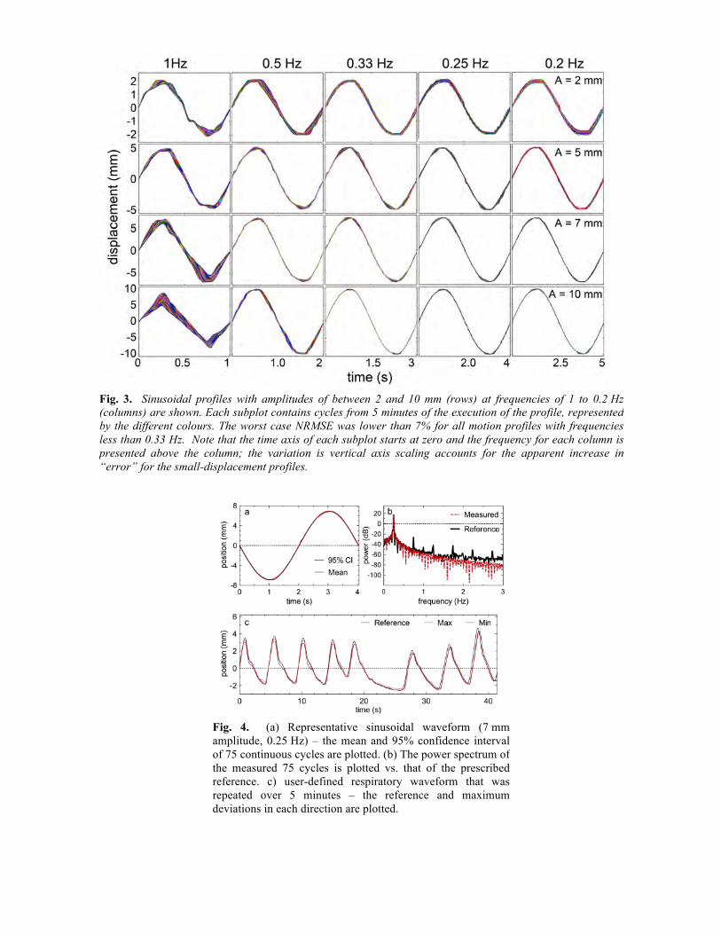
Fig. 3. Sinusoidal profiles with amplitudes of between 2 and 10 mm (rows) at frequencies of 1 to 0.2 Hz (columns) are shown. Each subplot contains cycles from 5 minutes of the execution of the profile, represented by the different colours. The worst case NRMSE was lower than 7% for all motion profiles with frequencies less than 0.33 Hz. Note that the time axis of each subplot starts at zero and the frequency for each column is presented above the column; the variation is vertical axis scaling accounts for the apparent increase in “error” for the small-displacement profiles.
Fig. 4. (a) Representative sinusoidal waveform (7 mm amplitude, 0.25 Hz) – the mean and 95% confidence interval of 75 continuous cycles are plotted. (b) The power spectrum of the measured 75 cycles is plotted vs. that of the prescribed reference. c) user-defined respiratory waveform that was repeated over 5 minutes – the reference and maximum deviations in each direction are plotted.
3.B. Accuracy inside the MRI scanner
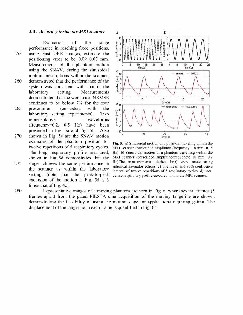
Evaluation of the stage performance in reaching fixed positions, using Fast GRE images, estimate the 255 positioning error to be 0.09±0.07 mm. Measurements of the phantom motion using the SNAV, during the sinusoidal motion prescriptions within the scanner, demonstrated that the performance of the 260 system was consistent with that in the laboratory setting. Measurements demonstrated that the worst case NRMSE continues to be below 7% for the four prescriptions (consistent with the 265 laboratory setting experiments). Two representative waveforms (frequency=0.2, 0.5 Hz) have been presented in Fig. 5a and Fig. 5b. Also shown in Fig. 5c are the SNAV motion 270 estimates of the phantom position for twelve repetitions of 5 respiratory cycles. The long respiratory profile measured, shown in Fig. 5d demonstrates that the stage achieves the same performance in 275 the scanner as within the laboratory setting (note that the peak-to-peak excursion of the motion in Fig. 5d is 3 times that of Fig. 4c).
Representative images of a moving phantom are seen in Fig. 6, where several frames (5 280 frames apart) from the gated FIESTA cine acquisition of the moving tangerine are shown, demonstrating the feasibility of using the motion stage for applications requiring gating. The displacement of the tangerine in each frame is quantified in Fig. 6c.
Fig. 5. a) Sinusoidal motion of a phantom traveling within the MRI scanner (prescribed amplitude /frequency: 10 mm, 0. 5 Hz). b) Sinusoidal motion of a phantom travelling within the MRI scanner (prescribed amplitude/frequency: 10 mm, 0.2 Hz)The measurements (dashed line) were made using spherical navigator echoes. c) The mean and 95% confidence interval of twelve repetitions of 5 respiratory cycles. d) user-define respiratory profile executed within the MRI scanner.

285
3.C. Performance under different scanning conditions
With the carriage center of motion placed at the isocenter, and within the head coil, the motion stage was able to perform only with the gradient echo EPI pulse sequence, however moving the stage back by only 5 cm ensured that the stage worked with all pulse sequences tested. When the torso coil was used, the distance from isocenter had to be increase to 10 cm to 290 ensure that the stage would operate. 3.D. Effect of the stage on image artifact, field homogeneity and SNR
Results show that the motion stage does not introduce image artifacts. Figure 7 shows SE and GRE center-slice images of the phantom both with and without the stage, alongside the corresponding artifact image (a binary map where white represents variations of 30% or more); 295
Fig. 6. a) Drawing of the phantom setup, direction of motion and the slice orientation is shown. b) Selected frames from the FIESTA cine sequence of a tangerine undergoing 0.33-Hz sinusoidal motion with 5-mm amplitude. c) The measured displacement, through calculating the centroid of the tangerine phantom, over the 30 frames is shown.

the sample images were acquired with the read direction set left-right (L/R) but the same results were obtained with the read direction flipped. The SNR measurement experiments showed an SNR of 91 dB for 300 the SE images that did not change with the stage present and active.
The effect of stage on B0 is illustrated in Fig. 8, where a sagittal ΔB 0 map is shown; the relative position of the 305 phantom with respect to the stage when the images were acquired is also shown. As can be seen, the worst-case B0 variation was less than 2 ppm and rapidly trailed off away from the motor, which 310 despite being MRI compatible contains metal components (e.g. aluminum case).
4. DISCUSSION In this paper we introduced an
MRI compatible linear motion stage that 315 is actuated with an ultrasonic motor. Our results show that the motion stage is highly accurate in reaching fixed positions, with an absolute error of 0.025±0.021 mm, and is highly consistent 320 and robust in executing dynamic motion profiles with a worst case NRMSE of 7% for frequencies of 0.33Hz and below. We have also shown that the motion stage does not introduce any artifacts (as per 325 the ASTM standard),44 introduces negligible B0 field inhomogeneity (with an induced variation of less than 2 ppm), and does not impact the SNR of the obtained images. Evaluation of the stage within a 3T MR scanner during imaging showed that the accuracy of the motion measured within the laboratory 330 setting is maintained when used in the scanner. Cine images also confirmed that the prescribed sinusoidal motion was highly consistent with the expected motion.
The obtained results indicate that the motion stage is fully MRI compatible and can be used to create accurately controlled dynamic motion for prolonged periods directly inside the bore of the scanner. As the executed motion profiles are known a priori, and can be reproduced 335 with high accuracy, the proposed system can be used to validate motion correction techniques and to be incorporated within MR-guided radiotherapy studies evaluating motion compensation strategies. While not specifically demonstrated in this paper, the materials of the phantom are also fully x-ray, PET, and SPECT compatible and the stage can be used in hybrid scanners or independently. Other commercial products are available to move an object in the MRI 340
Fig. 7. Representative images acquired with and without the stage present and working. The artifact images (right column) represent variations greater than 30% from baseline. Spin echo (a) and gradient echo (b) images with phase encoding in the left/right direction are shown; similar results were obtained with phase encoding in the anterior/posterior direction.
Fig. 8. The sagittal view of the map due to the stage is shown. The dashed yellow line indicates the location of the carriage at home position. The figure also illustrates where the stage was positioned with respect to the phantom.

environment, such as the MRI-LINAC Dynamic Phantom from CIRS (Norfolk, Virginia), however this product does not use MRI compatible motors, requiring the motors to be at a long distance from the scanner. To the best knowledge of the authors, another limitation of this system is that it is only compatible with a single type of phantom (i.e. the user cannot choose to move a different object). A similar product, designed to move a set of phantom inserts is also 345 under development by Modus Medical (London, Ontario), but it also does not provide the versatility presented by the linear stage presented in this manuscript; specifically the system does not allow moving of conventional phantoms. The stage described in this manuscript is a prototype of a commercially available system (MR-1A-XRV2, ViTal Biomedical Technologies, London, Ontario). 350
Due to the bounded speed limits of the USM, the error in motion control increases as the speed requirements pass beyond the USM’s speed limits. As discussed in the paper, the NRMSE for a frequency of 1 Hz can be as high as 30% depending on the amplitude of the motion. Therefore, desired motion profiles must be prescribed with consideration of the motor’s capabilities. For example, as can be seen in Fig 4.c and Fig. 5d, the tracking performance 355 degrades when tracking a reference motion with very high frequency components as the maximum speed of the motor is limited. Looking at Fig 4.c, 5d we can also observe that the tracking performance may degrade when tracking motion profiles with extremely low frequency components as the motor has a non-zero minimum speed.
Based on the recorded encoder counts, the closed loop control system appears to track the 360 reference signal with high accuracy and consistency. However, as was shown in Fig. 3 the profiles tracked with the optical tracking system demonstrated a small but measurable variability in successive profiles. This inconsistency suggests that the system, as implemented, was missing encoder counts. Modification of the method used to decode the signals from the optical encoder or use of an absolute encoder are expected to remove this problem and reduce the variability 365 even further.
Using ultrasonic motors also presents another limitation, namely the maximum operating temperature (~ 45 °C) and the change in operating characteristics as the temperature increases. In the presented implementation of the motion stage, experiments were performed for a maximum duration of 5 minutes, which is sufficient for the majority of imaging experiments. The 370 development of an improved robust USM control mechanism42, 47 has resulted in maintenance of the accurate performance of the device for prolonged periods; including a simple heat sink on the motor further reduces the temperature and accurate waveforms can be generated for periods of up to an hour. Note that the robust control mechanism implemented here will ensure that there is no degradation in performance with increased temperature; as programmed, the stage will 375 automatically turn off if the maximum operating temperature is approached. 42
The carriage of the stage is designed to support adaptors for various applications. This feature provides the user the option to place phantoms of various shapes directly on top of the carriage (e.g. Fig. 1) or move a phantom mounted on a platform extender for use with smaller RF coils (e.g. Fig. 6b). The adaptors can also be configured to deform flexible phantoms by 380 pushing/pulling on the phantom. In addition, if longer travel is required, the mechanical components of the stage can be modified to extend the travel, which is only limited by the length of the lead screw and supporting components.
The field distortion introduced by the stage is primarily caused by the motor, which is encased in an aluminum case. The minor field inhomogeneities introduced by the motor are 385 smaller than the chemical shift between fat and water (3.5 ppm) and any distortions that are introduced (as can be seen in the gradient echo image of Fig. 7b) are considered insignificant for
most applications. For applications that require no distortion, the addition of a simple carriage adaptor, as those described above, that moves the phantom farther from the motor than the center of the carriage will ensure that no distortion from the motion stage motor is present. 390
One limitation of this system is that when the motor is very close to the isocenter it is possible that some pulse sequences (e.g. GRE with large flip angles, DWI, FSE) may introduce extensive noise on the encoder signal line, resulting in device malfunction. Our tests demonstrate that a distance of a minimum of 10 cm between the center of motion and isocenter is sufficient for even the most RF-intensive pulse sequences. Alternatively, the stage can be 395 redesigned so an adapter can be used to move the stage such that the motor is approximately 20 cm from the isocenter permitting accurate and reliable function of the device. As mentioned in the paper the filters used to filter the signal line were low pass capacitive filters (1000 PF). It is possible that a higher order filter would help further improve the performance of the system at isocenter and allow complete elimination of any interference. Such a filter must be optimally 400 designed so that it eliminates interference without degrading the encoder feedback data. These improvements will be considered as part of future work.
The presented motion stage provides a means of creating consistent and accurately controlled motion profiles inside the scanner during imaging. The small footprint of the stage allows arbitrary positioning and orientation of the stage and allows moving of conventional 405 phantoms. The system can be used for various applications that are sensitive to motion. Examples include but are not limited to evaluation of: motion estimation, multimodality image registration, tracking accuracy and MRI guided therapy of moving targets.
5. CONCLUSION The presented motion stage is MRI compatible and is capable of producing accurate and 410
consistent motion profiles inside the scanner during imaging without introducing artifacts, inhomogeneities, or additional noise. The system provides an easy means to provide a ground truth of motion for MRI applications that are sensitive to motion.
ACKNOWLEDGMENTS The authors thank Dr. Blaine Chronik for his generous advice. The authors acknowledge 415
funding from the Canadian Institutes of Health Research and the Natural Sciences and Engineering Research Council of Canada. M.A.T. was funded by an Ontario Graduate Scholarship and M.D. is a Career Investigator of the Heart and Stroke Foundation of Ontario. Disclosure: M.A.T. and M.D. are co-founders of ViTAL Biomedical Technologies.

Preprint of Med Phys. 2016 Jan;43(1):62. doi: 10.1118/1.4937780.
REFERENCES 1 M.L. Wood, R.M. Henkelman, "MR image artifacts from periodic motion," Medical Physics 12, 143-151 (1985). 2 R.L. Ehman, J. Felmlee, "Adaptive technique for high-definition MR imaging of moving structures," Radiology
173, 255-263 (1989). 3 J. Liu, M. Drangova, "Rapid six-degree-of-freedom motion detection using prerotated baseline spherical
navigator echoes," Magn Reson Med 65, 506-514 (2011). 4 A. Alhamud, M.D. Tisdall, A.T. Hess, K.M. Hasan, E.M. Meintjes, A.J. van der Kouwe, "Volumetric navigators
for real-time motion correction in diffusion tensor imaging," Magn Reson Med 68, 1097-1108 (2012). 5 J.Y. Cheng, M.T. Alley, C.H. Cunningham, S.S. Vasanawala, J.M. Pauly, M. Lustig, "Nonrigid motion
correction in 3D using autofocusing with localized linear translations," Magn Reson Med 68, 1785-1797 (2012). 6 M. Henningsson, J. Smink, R. Razavi, R.M. Botnar, "Prospective respiratory motion correction for coronary MR
angiography using a 2D image navigator," Magn Reson Med 69, 486-494 (2013). 7 J. Maclaren, M. Herbst, O. Speck, M. Zaitsev, "Prospective motion correction in brain imaging: a review," Magn
Reson Med 69, 621-636 (2013). 8 J. Pang, H. Bhat, B. Sharif, Z. Fan, L.E. Thomson, T. LaBounty, J.D. Friedman, J. Min, D.S. Berman, D. Li,
"Whole-heart coronary MRA with 100% respiratory gating efficiency: self-navigated three-dimensional retrospective image-based motion correction (TRIM)," Magn Reson Med 71, 67-74 (2014).
9 J.A. Steeden, D.S. Knight, S. Bali, D. Atkinson, A.M. Taylor, V. Muthurangu, "Self-navigated tissue phase mapping using a golden-angle spiral acquisition-proof of concept in patients with pulmonary hypertension," Magn Reson Med 71, 145-155 (2014).
10 Z. Celicanin, O. Bieri, F. Preiswerk, P. Cattin, K. Scheffler, F. Santini, "Simultaneous acquisition of image and navigator slices using CAIPIRINHA for 4D MRI," Magn Reson Med 73, 669-676 (2015).
11 S. Nordmeyer, E. Riesenkampff, D. Messroghli, S. Kropf, J. Nordmeyer, F. Berger, T. Kuehne, "Four-dimensional velocity-encoded magnetic resonance imaging improves blood flow quantification in patients with complex accelerated flow," JMRI - Journal of Magnetic Resonance Imaging 37, 208-216 (2013).
12 K.P. McGee, A. Kolipaka, P. Araoz, A. Manduca, A. Romano, R.L. Ehman, "Magnetic Resonance Elastography of the Heart," in Magnetic Resonance Elastography (Springer, 2014), pp. 109-117.
13 C.L. Johnson, M.D. McGarry, E.E. Houten, J.B. Weaver, K.D. Paulsen, B.P. Sutton, J.G. Georgiadis, "Magnetic resonance elastography of the brain using multishot spiral readouts with self‐navigated motion correction," Magn Reson Med 70, 404-412 (2013).
14 Y.K. Mariappan, A. Kolipaka, A. Manduca, R.D. Hubmayr, R.L. Ehman, P. Araoz, K.P. McGee, "Magnetic resonance elastography of the lung parenchyma in an in situ porcine model with a noninvasive mechanical driver: Correlation of shear stiffness with trans‐respiratory system pressures," Magn Reson Med 67, 210-217 (2012).
15 S.Y. Chun, T.G. Reese, J. Ouyang, B. Guerin, C. Catana, X. Zhu, N.M. Alpert, G. El Fakhri, "MRI-based nonrigid motion correction in simultaneous PET/MRI," Journal of Nuclear Medicine 53, 1284-1291 (2012).
16 C. Catana, "Motion correction options in PET/MRI," Semin Nucl Med 45, 212-223 (2015). 17 H. Fayad, H. Schmidt, C. Wuerslin, D. Visvikis, "Reconstruction-Incorporated Respiratory Motion Correction in
Clinical Simultaneous PET/MR Imaging for Oncology Applications," J Nucl Med 56, 884-889 (2015). 18 S. Furst, R. Grimm, I. Hong, M. Souvatzoglou, M.E. Casey, M. Schwaiger, S.G. Nekolla, S.I. Ziegler, "Motion
correction strategies for integrated PET/MR," J Nucl Med 56, 261-269 (2015). 19 S. Crijns, B. Raaymakers, J. Lagendijk, "Proof of concept of MRI-guided tracked radiation delivery: tracking
one-dimensional motion," Physics in Medicine and Biology 57, 7863 (2012). 20 M.K. Stam, S.P. Crijns, B.A. Zonnenberg, M.M. Barendrecht, M. van Vulpen, J.J. Lagendijk, B.W. Raaymakers,
"Navigators for motion detection during real-time MRI-guided radiotherapy," Physics in Medicine and Biology 57, 6797 (2012).
21 L. Brix, S. Ringgaard, T.S. Sorensen, P.R. Poulsen, "Three-dimensional liver motion tracking using real-time two-dimensional MRI," Med Phys 41, 042302 (2014).
22 J.J. Lagendijk, B.W. Raaymakers, C.A. Van den Berg, M.A. Moerland, M.E. Philippens, M. van Vulpen, "MR guidance in radiotherapy," Physics in Medicine and Biology 59, 349 (2014).
23 D. Lee, S. Pollock, B. Whelan, P. Keall, T. Kim, "Dynamic keyhole: a novel method to improve MR images in the presence of respiratory motion for real-time MRI," Med Phys 41, 072304 (2014).
24 R. Van der Put, E. Kerkhof, B. Raaymakers, I. Jürgenliemk-Schulz, J. Lagendijk, "Contour propagation in MRI-guided radiotherapy treatment of cervical cancer: the accuracy of rigid, non-rigid and semi-automatic registrations," Physics in Medicine and Biology 54, 7135 (2009).
25 M. Henningsson, J. Smink, R. Razavi, R.M. Botnar, "Prospective respiratory motion correction for coronary MR angiography using a 2D \ image navigator," Magn Reson Med\ 69\, 486-494\ (2013).
26 C. Stehning, P. Bornert, K. Nehrke, H. Eggers, M. Stuber, "Free-breathing whole-heart coronary MRA with 3D radial SSFP and self-navigated\ image reconstruction," Magn Reson Med\ 54\, 476-480\ (2005).
27 Y. Liu, F.F. Yin, N.K. Chen, M.L. Chu, J. Cai, "Four dimensional magnetic resonance imaging with retrospective k-space reordering: a feasibility study," Med Phys 42, 534-541 (2015).
28 N.C. von Sternberg, Y.S. Hedayati, H.M. Zaid, E. Yeniaras, E. Christoforou, N.V. Tsekos, presented at the Biomedical Robotics and Biomechatronics (BioRob), 2012 4th IEEE RAS & EMBS International Conference on2012 (unpublished).
29 Z. Celicanin, V. Auboiroux, O. Bieri, L. Petrusca, F. Santini, M. Viallon, K. Scheffler, R. Salomir, "Real‐time method for motion‐compensated MR thermometry and MRgHIFU treatment in abdominal organs," Magn Reson Med 72, 1087-1095 (2014).
30 M. Drangova, B. Bowman, N.J. Pelc, "Physiologic motion phantom for MRI applications," Journal of Magnetic Resonance Imaging 6, 513-518 (1996).
31 M. Günther, D.A. Feinberg, "Ultrasound‐guided MRI: Preliminary results using a motion phantom," Magn Reson Med 52, 27-32 (2004).
32 S. Kee, E. Larsen, K. Paluch, R. Sinke, K. Yan, J. Pilla, C. Xu, presented at the Bioengineering Conference, Proceedings of the 2010 IEEE 36th Annual Northeast2010 (unpublished).
33 M. Fieseler, H. Kugel, F. Gigengack, T. Kösters, F. Büther, H.H. Quick, C. Faber, X. Jiang, K.P. Schäfers, "A dynamic thorax phantom for the assessment of cardiac and respiratory motion correction in PET/MRI: A preliminary evaluation," Nuclear Instruments and Methods in Physics Research Section A: Accelerators, Spectrometers, Detectors and Associated Equipment 702, 59-63 (2013).
34 V. Tavakoli, M. Kendrick, M. Shakeri, M. Alshaher, M.F. Stoddard, A. Amini, presented at the SPIE Medical imaging, San Diego, CA, 2013 (unpublished).
35 D. Stoianovici, A. Patriciu, D. Petrisor, D. Mazilu, L. Kavoussi, "A new type of motor: pneumatic step motor," Mechatronics, IEEE/ASME Transactions on 12, 98-106 (2007).
36 Y. Chen, K.-W. Kwok, Z.T.H. Tse, "An MR-Conditional High-Torque Pneumatic Stepper Motor for MRI-Guided and Robot-Assisted Intervention," Annals of biomedical engineering 42, 1823-1833 (2014).
37 R. Secoli, M. Robinson, M. Brugnoli, F.R. y Baena, "A low-cost, high-field-strength magnetic resonance imaging–compatible actuator," Proceedings of the Institution of Mechanical Engineers, Part H: Journal of Engineering in Medicine 229, 215-224 (2015).
38 R. Chopra, L. Curiel, R. Staruch, L. Morrison, K. Hynynen, "An MRI-compatible system for focused ultrasound experiments in small animal models," Med Phys 36, 1867-1874 (2009).
39 C. Yiallouras, C. Damianou, "Review of MRI positioning devices for guiding focused ultrasound systems," Int J Med Robot 11, 247-255 (2015).
40 N.P. Ellens, I. Kobelevskiy, A. Chau, A.C. Waspe, R.M. Staruch, R. Chopra, K. Hynynen, "The targeting accuracy of a preclinical MRI-guided focused ultrasound system," Med Phys 42, 430-439 (2015).
41 M.A. Tavallaei, M. Drangova, Patent No. US 13/764,425 (2013). 42 M.A. Tavallaei, F. Atashzar, M. Drangova, "Robust Motion Control of Ultrasonic Motors Under Temperature
Disturbance," IEEE Trans Ind Electron2015, in press). 43 T. Kawano, E. Ohtake, T. Inoue, "Deep-inspiration breath-hold PET/CT versus free breathing PET/CT and
respiratory gating PET for reference: evaluation in 95 patients with lung cancer," Ann Nucl Med 25, 109-116 (2011).
44 A. Standard, "F2119-07. Standard Test Method for Evaluation of MR Image Artifacts from Passive Implants," ASTM International, West Conshohocken, Pa, USA2006).
45 J. Liu, M. Drangova, "Method for B0 off-resonance mapping by non-iterative correction of phase-errors (B0-NICE)," Magn Reson Med2014).
46 NEMA, "Determination of Signal-to-Noise Ratio (SNR) in Diagnostic Magnetic Resonance Imaging," (National Electrical Manufacturers Association, 2008).
47 M.A. Tavallaei, M. Drangova, Patent No. US 13/764,425 (2014).