design and fabrication and testing of a low speed …
TRANSCRIPT

870
DESIGN AND FABRICATION AND TESTING OF A LOW SPEED WIND TURBINE GENERATOR USING TAPERED TYPE ROTOR BLADE MADE FROM FIBRE REINFORCED PLASTIC
C. O. Saoke1, Y. Nishizawa2, I. Ushiyama2, J. Kamau1, R. Kinyua1 and Y. Nakajo2 1Division of Renewable Energy Engineering Ashikaga Institute of Technology – Japan 2Department of Physics, Jomo Kenyatta University of Agriculture and Technology, Nairobi, Kenya E-mail: [email protected] Abstract This study fabricated a three bladed wind turbine of 0.6 m rotor diameter. The blade was divided into ten sections and shape derived from the blade element and momentum theory with two linearization points at 70% and 90%.. Other design values chosen were; clark Y as the airfoil type, 2.5 as tip speed ratio, 1.1 as lift drag ratio, design angle of attack of 8o. The rotor blades were fabricated using two layers of fibre reinforced plastic and 2% hardenning on resin. The power coefficient of the turbine was tested in the wind tunnel by subjecting it to wind speeds ranging from 4 m/s to 10 m/s in the wind tunnel testing. The wind tunnel used for the study was the Effel type with an exit of 1.05 mX1.05 m and wind speed adjustable between 2 m/s to 22.5 m/s. An induction motor was used to provide the load in the experiment and the synchronized frequency controlled by an inverter. A direct connection generator was employed to the turbine rotors to determine the electricity generation capacity. The maximum coefficient of power for the blade was found to be 0.26 at 10 m/s and 651 rpm. A variable resistance was used to determine the electric power production at different rotational speed. A speed of 10 m/s gave the highest power of 29.69 W at 891 rpm, 8 m/s gave the highest power as 15.43 W at 688 rpm, 6 m/s gave the highest power as 6.38 W at 552 rpm while 4 m/s gave the highest power as 1.74 W at 302 rpm. The Wind generator was then used to charge a 54 AH, 12 V battery producing the highest electrical power of 32.03 W. The turbine is capapble of producing power and would be applicable within area with low wind regimes providing power for small household usage. However it is recommended that the design should be optimized to improve the coefficient of power. Key words: Coefficient of power, tip speed ratio, angle of attack, wind tunnel, wind speed, tapered type, rotor
blade 1.0 Introduction There are two major types of wind turbines namely the horizontal axis wind turbine (HAWT) and the vertical axis wind turbine (VAWT). The former is the most common type of wind turbine; their shafts have a set of blades that rotate about an axis parallel to the flow direction. Major research and development of wind energy generators has focused more on this type of wind turbine because they share common operation and dynamics with rotary aircraft. The latter type of wind turbine rotates about an axis that is perpendicular to the wind direction; hence, it can take wind from any direction. VAWTs consist of two major types, the Darrieus rotor and Savonius rotor. The Darrieus wind turbine is a VAWT that rotates around a central axis due to the lift produced by the rotating airfoils, whereas a Savonius rotor rotates due to the drag created by its blades. There is also a new type of VAWT emerging in the wind power industry which is a mixture between the Darrieus and Savonius designs. (Travis. et al. 2012) The large-scale wind turbines with the grid connection system operated in wind farms are being used for the power generation in many advanced nations. On the other hand, the small-scale wind turbines have been used as the independent source of electricity regardless of the locations. In recent years, these small wind turbines of a diameter under 2 m are employed for street lights, park lights, environmental monuments, power sources for emergencies and teaching materials. Because such small wind turbines are usually installed in urban areas, the noise generate from rotor, the failures due to the sudden changes of the wind direction and wind speed which are peculiar to those areas became particularly noticeable these days with increase of the installation. The rotors for small wind turbines designed to have low tip speed ratio are increasing in number because of their reduced noise. The development of generators and controllers suitable for low rotational speed has largely accelerated these years. While there are many studies on the small wind turbine rotors with high tip speed ratio

871
adjusted for conventional generators, (Duquette et al., 2003) the number of the paper systematically dealing the rotor shapes applied for low tip speed ratio is very small. Wind turbine blades are shaped to generate the maximum power from the wind at the minimum cost. Primarily the design is driven by the aerodynamic requirements, but economics mean that the blade shape is a compromise to keep the cost of construction reasonable. In particular, the blade tends to be thicker than the aerodynamic optimum close to the root, where the stresses due to bending are greatest. The blade design process starts with a “best guess” compromise between aerodynamic and structural efficiency. The choice of materials and fabrication process will also have an influence on how thin (hence aerodynamically ideal) the blade can be built. For instance, carbon fiber is stiffer and stronger than infused glass fiber. The chosen aerodynamic shape gives rise to loads, which are fed into the structural design. Problems identified at this stage can then be used to modify the shape if necessary and recalculate the aerodynamic performance. 1.1 Aerodynamics In the design and fabrication of wind turbine rotor blade, understanding the efficiency of the aerodynamic performance is very critical (Maalawi et al. 2003). The lift force which produces the power yield generated by the rotor must be maximized at the design stage. Conversely, the drag force is generated by friction and it’s a force that resists the blade motion. The design should therefore minimize the drag force. A high lift to drag ratio is recommended for an aerofoil section if the performance of the turbine is to be optimized (Griffiths 1977). Due to the challenges of mathematically predicting an aerofoil’s lift and drag co-efficient, XFOIL software is applicable to model results accurately (Drela 2000). Designs of wind turbine aerofoil are drawn from that of the aircraft technologies with similar Reynolds numbers and section thicknesses suitable for conditions at the blade tip. However, other considerations are made for the design of wind turbine specific aerofoil profiles as a result of the differences in conditions of operation and mechanical loads. For designing of aerofoils, such parameters such as tip speed ratio, Blade pitch angle, Blade pitch angle, the angle of attack are fundamental and they can be derived from the combined blade element and momentum theory
Local tip speed ratio: R
rdrd ……………………………………………………………………………………………. (1)
Inflow angle: rd
1 1tan3
2
…………………………………………………………………………………………………. (2)
Blade pitch angle: …………………………………………………………………………………………………. (3)
Blade pitch angle: cos1
8
BC
rC ………………………………………………………………………………… (4)
Where; B is Number of blades, C is Chord length[m], R is Rotor radius[m], r is Local rotor radius[m], rd is Local
design tip speed ratio, d is Design tip speed ratio, is Inflow angle, is Design angle of attack, is Blade pitch
angle 2.0 Methodology The methodology involved two stages namely; i) Design and fabrication ii) Wind tunnel testing. 2.1 Design and Fabrication This encompassed the design of the rotor blade from the theory of blade element momentum and fabrication from the design parameters in Table 1. Table 1: Preliminary design values of blade
Rotor diameter[mm] 600.0
Number of blades 3.0
Generator RPM 750.0
Power rating [W] 25.0
Design tip speed ratio 2.5

872
The Clark Y aerofoil was chosen for the blade design and the experimental data of low speed aerofoil (Michael et al. 1995) at a Reynolds’s number of 1 x 10⁵ was used to determine the best design angle of attack design lift coefficient as shown in Figure 2. Figure 2: CL, CD verses angle of attack (Michael et al. 1995) The rotor blade was modelled and designed according to the combined blade element and momentum theory by equation 1, 2, 3, and 4. The dimensions of each of the blade sections were calculated and linearization done using two points i.e. 70% and 90%. Table 2 shows the result from the calculations and those of the linearization as used for the model design. These points were expressed as a percentage of the span direction from the root location. Table 2: Calculated and linearized dimensions of the blade sections
Theoretical value Linearized value Magnification
Span point
Pitch angle
Chord length (mm)
Pitch angle Chord length (mm) (X200 mm)
10% 42.9o 83.6 23.4 o 141.1 0.705
20% 34.3 o 118.9 21.5 o 133.4 0.667
30% 27.4 o 126.9 19.5 o 125.7 0.628
40% 22.0 o 122.4 17.6 o 118.0 0.590
50% 17.8 o 113.6 15.7 o 110.3 0.551
60% 14.5 o 104.0 13.8 o 102.5 0.512
70% 11.8 o 94.8 11.8 o 94.8 0.474
80% 9.7 o 86.6 9.9 o 87.1 0.435
90% 8.0 o 79.4 8.0 o 79.4 0.397
100% 6.5 o 73.1 6.0 o 72.7 0.358
α=8
CL=1.1
873
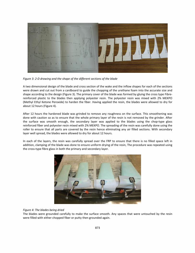
Figure 3: 2-D drawing and the shape of the different sections of the blade
A two dimensional design of the blade and cross section of the wake and the inflow shapes for each of the sections were drawn and cut out from a cardboard to guide the chopping of the urethane foam into the accurate size and shape according to the design (Figure 3). The primary cover of the blade was formed by gluing the cross type Fibre-reinforced plastic to the blades then applying polyester resin. The polyester resin was mixed with 2% MEKPO (Methyl Ethyl Ketone Peroxide) to harden the fiber. Having applied the resin, the blades were allowed to dry for about 12 hours (Figure 4). After 12 hours the hardened blade was grinded to remove any roughness on the surface. This smoothening was done with caution so as to ensure that the whole primary layer of the resin is not removed by the grinder. After the surface was smooth enough, the secondary layer was applied to the blades using the chop-type glass reinforced fiber and polyester resin mixed with 2% MEKPO. The spreading of the resin was carefully done using the roller to ensure that all parts are covered by the resin hence eliminating any air filled sections. With secondary layer well spread, the blades were allowed to dry for about 12 hours. In each of the layers, the resin was carefully spread over the FRP to ensure that there is no filled space left in addition, clamping of the blade was done to ensure uniform drying of the resin, The procedure was repeated using the cross-type fibre glass in both the primary and secondary layer.
Figure 4: The blades being dried The blades were grounded carefully to make the surface smooth. Any spaces that were untouched by the resin were filled with either chopped fiber or putty then grounded again.

874
2.2 Wind Tunnel Testing This stage encompassed the testing of the torque and testing of the electrical generation capacity of the wind electric generator in the wind tunnel. The wind tunnel used had the following specifications: maximum wind speed – 23 m/s, 1.05 x 1.05 m2, 1.522 m3/min, 20-250 rpm and 30 kW. The blades were joined together in a crunch with bolts using a plate designed as the in the Figure 5. Figure 6 shows a schematic diagram of the wind tunnel set-up.
Figure 5: The design of the crunch and the blades fixed on the crunch
Figure 6: Schematic diagram of the wind tunnel setup The turbine rotor was subjected to a range of wind speed from 4 m/s to 10 m/s. For each of the wind speeds the inverted frequency was increased to increase the rpm until there is no torque (ensuring that the 1000rpm limit is not exceeded.) After the point of zero torque was reached, the rotational speed was then gradually reduced at intervals of 50 rpm while recording the corresponding torque. The vibration level for the turbine was also observed to be between 700-750 rpm (Figures 7-9). The recorded results we used to calculate coefficients of power, coefficient torque and also to draw the power curves.

875
Figure 7: Wind tunnel testing of the turbine rotor A direct connection generator E002L, 750 RPM and 25 W rating was used on the RFP fabricated wind turbine rotor to study its capacity to generate electrical power.
Figure 8: The generator and its design A variable resistor was then employed and used to determine the electrical power generation of the Wind electric generator at different rotational speeds for different wind speeds. A 54 AH, 12V battery was connected as the load and the wind speed varied as the corresponding current, voltage and RPM were recorded.

876
Figure 9: Testing the wind electric generator for electricity production 3.0 Results and Discussion For the different wind speeds tested, the RFP rotor blade gave power coefficient maxima as shown in table 3. Although the design wind speed for the turbine was 8 m/s, from the results the turbine’s capacity to capture power at lower wind speeds was still considerable. Moreover the best highest Cp for all the wind speeds tested was achieved at an rpm that is lower than the vibration point (700-750 rpm). Table 3: Power coefficient maxima at different wind speeds
Wind speed (m/s) Rpm Torque (N.m)
TSR Cq Cp Power (W)
4.0 275 0.087 2.16 0.11 0.2314 2.51
6.0 451 0.193 2.36 0.11 0.2495 9.12
8.0 550 0.384 2.16 0.12 0.2562 22.12
10.0 651 0.653 2.05 0.13 0.2649 44.52
The power and torque coefficient curves for the different wind speeds are as shown in the figure 10 and 11 respectively. These power curves are very instrumental in assessing the performance of a turbine to capture wind energy. From theory, it is known that the tip speed ratio of a turbine helps to maximize the power output and efficiency of the wind turbine in that if a rotor spins too slowly, a lot of wind will pass through the gaps between the blades rather than giving energy to the turbine. Also if the blades spin too quickly, they could create too much turbulent air or act as a solid wall against the wind. So, the Tip Speed Ratio is helpful in maximizing the turbine’s efficiency. From the power curves, the power coefficient is optimum at around the design Tip Speed ratio, meaning that at this pick the turbine captures more power. Nevertheless, when the turbine is operating at extremes from the design value then the Cp is lowered because either more wind is passing through the blades without being slowed by the blades or the blades are moving too fast that they create a solid wall that blocks the wind like a wall.

877
Figure 10: Coefficient of power curve A higher tip speed demands reduced chord widths leading to narrow blade profiles. This can lead to reduced material usage and lower production costs. An increase in centrifugal and aerodynamic forces is associated with higher tip speeds. The increased forces signify that difficulties exist with maintaining structural integrity and preventing blade failure. As the tip speed increases the aerodynamics of the blade design become increasingly critical. A blade which is designed for high relative wind speeds develops minimal torque at lower speeds. This results in a higher cut in speed and difficulty self-starting. Large modern HAWT generally utilize a tip speed ratio of nine to ten for two bladed rotors and six to nine for three blades. This has been found to produce efficient conversion of the winds kinetic energy into electrical power. (Duquette et al., 2003)
Figure 11: Coefficient of torque curve Table 4 gives the results of the maximum electrical power output for different wind speeds while figures 12, 13 and 14 gives the variation of electrical power output, current and voltage with RPM at different wind speeds. Table 4: Maximum electrical power at different wind speeds

878
Wind speed [m/s]
Voltage [V]
Current [A]
Rotational speed [rpm]
Power output [W]
10 16.87 1.76 891 29.69
8 12.97 1.19 688 15.43
6 10.81 0.59 552 6.38
4 5.12 0.34 302 1.74
Figure 12: Variation of electrical power with RPM at different wind speeds
Figure 13: Variation of current with RPM at different wind speeds

879
Figure 14: Variation of electrical power output and current with RPM at different wind speeds Table 5 gives the results obtained while the wind turbine generator was used to charge a 54 AH, 12 V battery while Figure 16 shows the electrical power variation with wind speed on a battery load. At speeds lower than 4 m/s, the generator did not produce electrical power. However, as the electrical power increased with the increase in wind speed. The cut in wind speed for the generator can therefore be said to have been 4 m/s. the cut out wind speed could be established if the experiment was done to much higher wind speeds. Table 5: Results of battery charging by the WEG
Wind speed [m/s]
Voltage [V]
Current [A]
Rotational speed [rpm]
power [W]
2 12.77 0.00 268 0.00
3 12.77 0.00 402 0.00
4 12.81 0.06 503 0.77
5 12.90 0.25 532 3.23
6 13.07 0.52 567 6.80
7 13.27 0.84 606 11.15
8 13.57 1.22 651 16.56
9 16.32 1.45 772 23.66
10 16.68 1.92 831 32.03
At all the ranges of the wind speeds, the turbine can be able to meet power loads that range from lighting small power saver bulbs to powering electrical equipments. It will only be neccesary to calculate the power need so that the amount of time required to charge the battery can be established. Moreover, the due to power intemittency this battery bank will be necessary to ensure power stability during low wind resource.

880
Figure 15: Variation of electrical power with wind speed on a battery load 4.0 Conclusion The maximum coefficient of power for the blade was found to be 0.26 at 10 m/s and 651 revolutions per minute. A variable resistance was used to determine the electric power production at different rotational speed. A speed of 10 m/s gave the highest power of 29.69 W at 891 RPM, 8 m/s gave the highest power as 15.43 W at 688 RPM, 6 m/s gave the highest power as 6.38 W at 552 RPM while 4 m/s gave the highest power as 1.74 W at 302 RPM. The Wind generator was then used to charge a 54AH, 12V battery producing the highest electrical power of 32.03 W and no power at wind speeds lower than 3 m/s. Acknowledgements I acknowledge the support of JICA, Ashikaga Insitute of Technology and Jomo Kenyatta University and Technology. I would like to thank all all the persons and institutions for ther support.

881
References Travis, J. Carrigan, Brian, H. Dennis, Zhen, X. Han, and Bo P.Wang (2012). Aerodynamic Shape Optimization of a Vertical-Axis Wind Turbine Using Differential Evolution. International Scholarly Research Network Volume, Article ID 528418.
Drela, M. (2000). Xfoil. Massachusetts Institute of Technology: Cambridge, MA, USA.
Duquette, M. M., Visser, K. D., (2003). Numerical implications of solidity and blade number on rotor performance of horizontal-axis wind turbines. J. Sol. Energy Eng.-Trans. ASME, 125, pp 425–432.
Griffiths, R. T. (1977). The effect of aerofoil characteristics on windmill performance. Aeronaut. J., 81, pp 322–326.
Michael, S., Selig, J., Guglielmo, J. Andy, P. B. and Philippe, G.iguere (1995). Summary of Low-Speed Airfoil Data Volume 1. Soartech Publications, Virginia Beach, Virginia 23451, USA.
Maalawi, K. Y. and Badr, M. A. (2003). A practical approach for selecting optimum wind rotors. Renew. Energy, 28, pp 803–822.