design and fabrication of a hydrostatic testing system...
TRANSCRIPT

Defence R&D Canada – Atlantic
DEFENCE DÉFENSE&
Design and Fabrication of a Hydrostatic
Testing System for Submarine Nickel
Aluminum Bronze Valves
K.J. KarisAllenFACTS Engineering Inc.
FACTS Engineering Inc.PO Box 20039Halifax, Nova Scotia B3R 2K9
Project Manager: Y. Perron, 902-427-1930
Contract Number: W7707-078023/001/HAL
Contract Scientific Authority: DR. Y. Wang, 902-427-3035
The scientific or technical validity of this Contract Report is entirely the responsibility of the contractor and thecontents do not necessarily have the approval or endorsement of Defence R&D Canada.
Contract Report
DRDC Atlantic CR 2008-107
June 2008
Copy No. _____
Defence Research andDevelopment Canada
Recherche et développementpour la défense Canada

This page intentionally left blank.

Design and Fabrication of a Hydrostatic Testing System for Submarine Nickel Aluminum Bronze Valves
K.J. KarisAllen FACTS Engineering Inc.
FACTS Engineering Inc. PO Box 20039 Halifax, Nova Scotia B3R 2K9
Project Manager: Y. Perron, 902-427-1930 Contract Number: W7707-078023/001/HAL Contract Scientific Authority: Dr. Y. Wang, 902-427-3035 The scientific or technical validity of this Contract Report is entirely the responsibility of the contractor and the contents do not necessarily have the approval or endorsement of Defence R&D Canada.
Defence R&D Canada – Atlantic
Contract Report DRDC Atlantic CR 2008-107 June 2008
Scientific Authority
Yueping Wang
Approved by
John Hiltz
Head/Dockyard Laboratory (Atlantic)
Approved for release by
J. L. Kennedy
DRP Chair
© Her Majesty the Queen as represented by the Minister of National Defence, 2008
© Sa majesté la reine, représentée par le ministre de la Défense nationale, 2008
Original signed by Yueping Wang
Original signed by John Hiltz
Original signed by Ron Kuwahara for
Abstract
A test system for conducting hydrostatic testing of submarine valves has been designed and fabricated. The design consists of two main components, namely, a high pressure valve pressurization circulation loop, and an external ambient pressure external containment chamber. The high pressure circulation loop was designed to apply pressures between 0 psig and 5000 psig in accordance with DRDC’s specified requirement. The exterior (ambient pressure) chamber was designed to contain events including a high pressure water jet (in the case of a “leak before break” type of failure mode) and a kinetic energy impact event from one or more of the components associated with a high pressure flow loop (catastrophic failure of the valve components). The experiments conducted have verified that the hydrostatic test system was functioning according to specifications.
Résumé
Un système d’essai hydrostatique de vannes de sous-marins a été conçu et fabriqué. Ce système est composé de deux éléments principaux, à savoir une boucle de circulation de pressurisation de vanne haute pression et une chambre de confinement à pression ambiante externe. La boucle de circulation haute pression est conçue pour appliquer des pressions manomètriques variant de 0 lb/po2 à 5 500 lb/po2 conformément aux exigences spécifiées de RDDC. La chambre extérieure (pression ambiante) a été conçue pour contenir les événements, y compris un jet d’eau à haute pression (dans le cas d’un mode de défaillance de type « fuite avant rupture ») et un événement d’impact d'énergie cinétique provenant d’un ou de plusieurs des éléments reliés à une boucle à débit haute pression (défaillance catastrophique des éléments de vanne). Les expériences effectuées ont démontré que le système d’essai hydrostatique fonctionnait conformément aux spécifications.
DRDC Atlantic CR 2008-107 i

This page intentionally left blank.
ii DRDC Atlantic CR 2008-107

Executive Summary Introduction Nickel aluminium bronze (NAB) castings are employed as valves in the submarine seawater handling systems because of their superior strength and shock resistance. However, NAB castings are susceptible to selective phase corrosion (SPC) in seawater; particularly in stagnant, polluted seawater. As part of efforts to assess the structural integrity on the submarine NAB valves with corrosion damage, DRDC Atlantic has a plan to study hydrostatic response of NAB valves with various wall thicknesses and their failure modes. A hydrostatic testing system is required in order to carry out these studies. This contractual work focused on the design and fabrication of a hydrostatic testing system for testing submarine NAB valves.
Results The hydrostatic testing system consists of two main components, namely, a high pressure valve pressurization circulation loop, and an external ambient pressure external containment chamber. The high pressure circulation loop was designed to apply pressures between 0 psig and 5500 psig to the inside of a NAB valve in accordance with DRDC’s specified requirement. A low flow rate diaphragm pump was used in the circuit to generate applied pressure. Two sets of custom flange heads were also fabricated for sealing the submarine valve flanges based on a previous head design which provided an acceptable seal to 8000 psi. The exterior (ambient pressure) chamber was designed to contain events including a high pressure water jet (in the case of a “leak before break” type of failure mode) and a kinetic energy impact event from one or more of the components associated with a high pressure flow loop (catastrophic failure of the valve components). Significance The testing performed at DRDC Atlantic indicated that the hydrostatic testing system was functioning to the DRDC’s specification. The testing system has been used to evaluate the hydrostatic performance of two valves (designated SW226 and SW403) under various corrosion damage scenarios. Future Plan The hydrostatic testing system will be used to conduct more testing to evaluate the failure mode of the NAB valves. More end caps will be designed and made to accommodate new valves. The data acquisition system will be upgraded to acquire more strain data from the testing.
K KarisAllen, 2008, Design and Fabrication of a Hydrostatic Testing System for Submarine Nickel Aluminum Bronze Valves. DRDC Atlantic CR 2008-107. Defence R&D Canada – Atlantic.
DRDC Atlantic CR 2008-107 iii

Sommaire Introduction Les pièces moulées en bronze au nickel-aluminium (BNA) sont utilisés dans la fabrication de vannes dans les systèmes de traitement d’eau de mer des sous-marins à cause de leur plus grande résistance et de leur résilience. Toutefois, les pièces moulées BNA sont sujettes à la corrosion sélective (CS) dans l’eau de mer, en particulier dans l’eau de mer stagnante et polluée. Dans le cadre des efforts faits pour évaluer l’intégrité structurale des vannes BNA de sous-marins ayant des dommages de corrosion, RDDC Atlantique a dressé un plan en vue d’étudier la réaction hydrostatique des vannes BNA à parois de diverses épaisseurs et leurs modes de défaillance. Un système d’essai hydrostatique est donc requis pour effectuer ces études. Les travaux précisés dans le contrat portent sur la conception et la fabrication d’un système d’essai hydrostatique pour la mise à l’essai de vannes BNA de sous-marins.
Résultats Le système d’essai hydrostatique est composé de deux éléments principaux, à savoir une boucle de circulation de pressurisation de vanne haute pression et une chambre de confinement à pression ambiante externe. La boucle de circulation haute pression est conçue pour appliquer des pressions manomètriques variant de 0 lb/po2 à 5 500 lb/po2 à l’intérieur d’une vanne BNA conformément aux exigences spécifiées de RDDC. Une pompe à membrane à faible débit a été utilisée dans le circuit pour produire la pression appliquée. De plus, deux ensembles de têtes de brides ont été fabriquées sur demande pour rendre étanche les brides des vannes des sous-marins en se fondant sur un ancien concept de tête qui assurait une étanchéité acceptable à 8 000 lb/po2. La chambre extérieure (pression ambiante) a été conçue pour contenir des événements, y compris un jet d’eau à haute pression (dans le cas d’un mode de défaillance de type « fuite avant rupture ») et un événement d’impact d'énergie cinétique provenant d’un ou de plusieurs des éléments reliés à une boucle à débit haute pression (défaillance catastrophique des éléments de vanne). Importance des résultats Les essais effectués à RDDC Atlantique ont démontré que le système d’essai hydrostatique fonctionne conformément aux spécifications du RDDC. Le système d’essai a été utilisé pour évaluer le rendement hydrostatique de deux vannes (désignées SW226 et SW403) dans divers scénarios de dommages de corrosion. Recherches futures Le système d’essai hydrostatique doit être utilisé pour effectuer d’autres essais en vue d’évaluer le mode de défaillance des vannes BNA. De nouveaux obturateurs d'extrémité doivent être conçus et fabriqués pour accommoder les nouvelles vannes. Le système d’acquisition de données doit être mis à niveau afin d’acquérir davantage de données de contrainte des essais.
K KarisAllen, 2008, Design and Fabrication of a Hydrostatic Testing System for Submarine Nickel Aluminum Bronze Valves. RDDC Atlantique CR 2008-107. R & D pour la défense Canada - Atlantique.
iv DRDC Atlantic CR 2008-107

Table of contents
Abstract........................................................................................................................................ i
Executive Summary................................................................................................................... iii
Sommaire................................................................................................................................... iv
Table of contents ........................................................................................................................ v
List of figures ............................................................................................................................ vi
1. INTRODUCTION......................................................................................................... 1
2. HYDROSTATIC TEST SYSTEM DESIGN ................................................................ 2
2.1 Pressurized Valve Hydraulic Circulation Loop Design.................................... 2
2.2 External Containment Chamber Design ........................................................... 4
3. EXPERIMENTAL PROCEDURES.............................................................................. 6
3.1 Recommended Practice for Conducting a Hydrostatic Test............................. 6
3.1.1 Valve and Containment Chamber Configuration Set-up..................... 6
3.1.2 Valve Pressurization Test Procedure................................................... 7
4. SYSTEM VERIFICATION TESTS AND RESULTS................................................ 10
5. SUMMARY AND CONCLUSIONS.......................................................................... 12
6. REFERENCES............................................................................................................ 13
Distribution list ......................................................................................................................... 15
DRDC Atlantic CR 2008-107 v

List of figures
Figure 2.1. Schematic representation of the hydrostatic test system and containment chamber design. ................................................................................................................................. 2
Figure 2.2. Schematic representation of the high pressure hydraulic flow circuit. .................... 3
Figure 2.3. Schematic representation of the test system containment chamber design. ............. 5
Figure 3.1. Photograph showing the configuration of a valve inserted into the lower section of the containment chamber. ................................................................................................... 7
Figure 3.2. Photograph showing the functional relationship between the containment chamber, the pump, and the data acquisition electronics for a fully configured test. ......................... 9
Figure 4.1. Relationship between internal valve body pressure and material strain for a test conducted with submarine valve SW403. ......................................................................... 11
vi DRDC Atlantic CR 2008-107

1. INTRODUCTION
Nickel aluminum bronze (NAB) valve bodies are employed in submarine seawater handling systems owing to their superior mechanical properties. NAB is, however, susceptible to various degradation mechanisms in seawater, including selective phase corrosion of the aluminum rich phases from the as received microstructure. The modified microstructure results in a porous material with severely degraded mechanical properties. As such, material which has sustained selective phase corrosion is normally excluded in assessments designed to determine the structural integrity of a valve body. One method of assessing the structural integrity of a valve body is hydrostatic testing of the component. Hydrostatic testing applies a controlled internal pressure to the body and assesses integrity based on either dimensional changes to the body subsequent to testing (constant pressure test) or inferred dimensional changes owing to a system pressure drop (constant volume test). Alternatively, the valve body may be instrumented (using strain gauges) and the relationship between applied pressure and material strain characterized.
The current project is focused on the design and fabrication of a hydrostatic test system. There are two main considerations for the design of a hydrostatic test system. The first consideration is that the components subjected to the internal valve body pressure which are not fully enclosed within a containment vessel are rated for the maximum operating system pressure to ensure they can withstand the hydraulic shock wave associated with a rapid system depressurization produced by a through wall NAB valve body breach. The second consideration is that in the event of a catastrophic failure of the valve body, the damage tolerance of the containment vessel is capable of withstanding the ensuing impact from the valve body. The following sections provide a description of the hydrostatic test system fabricated for DRDC.
DRDC Atlantic CR 2008-107 1

2. HYDROSTATIC TEST SYSTEM DESIGN
A general schematic of the hydrostatic test system chamber design implemented is provided in Figure 2.1. The design consists of two basic components, namely, an internal high pressure valve pressurization circulation loop, and an external ambient pressure external containment chamber. The following sections provide the detail associated with the design of the two main components of the system.
Figure 2.1. Schematic representation of the hydrostatic test system and containment chamber design.
2.1 Pressurized Valve Hydraulic Circulation Loop Design
Figure 2.2 shows a general schematic of the high pressure hydraulic components integrated into the DRDC system. System hydraulic pressure was achieved through the incorporation of a model PSR-7800 diaphragm pump manufactured by EST Group Inc. The inlet requirements for the pump were a 25-125 psi air supply to drive the diaphragm and a separate connection to the municipal water mains to provide the hydraulic medium. Valves were incorporated into the inlet lines to isolate the pump from the air and water when required. The pump has a maximum outlet capacity of approximately 7800 psi which may be manually adjusted using
2 DRDC Atlantic CR 2008-107

the multi-turn valve control located on the top panel of the pump. The internal outlet valve arrangement of the pump has been configured to facilitate the application of either a constant pressure or a constant volume test.
The outlet from the pump was coupled to the submarine valve flange head using a high pressure hydraulic line. The outlet port from the submarine valve flange head was coupled to an inline ball valve, an optional secondary pressure relief valve, and a pressure sensor. The ball valve was utilized to bleed the air from the system prior to applying the pressure profile sequence to the submarine valve body. A pressure relief valve was included in the outlet circuit to limit the pressure sustained by the system. The relief valve supplied was factory set for a cracking pressure of 5600 psi. Manufacturer’s specifications for the valve guarantee a “dead tight seal” for pressures below 95 percent of the cracking pressure. A solid state electronic pressure sensor has also been included in the outlet line to monitor the internal valve body pressures during the test. The sensor requires 15 Vdc as input power and provides a 0-5 Vdc output signal which is proportional to the applied pressure within the sensor range (0-7500 psi).
Figure 2.2. Schematic representation of the high pressure hydraulic flow circuit.
The nominal maximum internal valve pressure for the testing proposed by DRDC was approximately 5000 psig. The cracking pressure associated with the pressure relief valve was approximately 5600 psig. Thus the components utilized for the construction of the high pressure circulation loop must have a nominal continuous operating pressure rating which meets or exceeds 5600 psig. Where possible, commercially available high pressure
DRDC Atlantic CR 2008-107 3

components were utilized for the system design. The minimum pressure rating for the commercial components utilized in the high pressure flow loop was 7250 psi (valve head outlet bleed valve). Various code requirements for commercial high pressure components typically employ a burst pressure to operating pressure safety factor of between 3 and 4.
Two sets of submarine valve flange heads were fabricated to conduct the verification test on the two valve sizes provided by DRDC for the project (valve identifications SW604 and SW226). The design of the flange heads was based on heads fabricated by FMF Cape Scott for a series of preliminary tests conducted for DRDC on similar valves. The preliminary testing indicated that the flange head design provided acceptable seals to an applied internal valve pressure of approximately 8000 psi. The respective flange heads were used as templates for determining the nominal flange and stud circle diameters, as well as head thickness (approximately 1.25 inches). The flange blanks were fabricated from an ASTM A-516, Grade 70 carbon steel material [1] with a minimum yield and ultimate stress of 260 MPa and 485 MPa, respectively.
ASME B16.5 [2] was employed to determine the continuous working pressure rating associated with head design. The stud circle diameter associated with the larger of the two valves (SW226) was measured as approximately 7.00 inches (it should be noted that the stud circle diameter did not conform to any of the standard flange templates specified in ASME B16.5). Using the bolt circle diameter in combination with the head thickness, ASME B16.5 indicates that the approximate rating for the non-standard flange heads was Class 1500. Based on the ASME B16.5 material group (ASTM A-516, Grade 70 is contained within material group 1.1), the continuous working pressure for a Class 1500 flange head is approximately 3705 psig for temperatures between –20oF and 100oF [2]. Since the rated working pressure is less than the cracking pressure associated with the pressure relief valve, the heads should only be employed when completely enclosed within the containment chamber fabricated.
Attachment of the flange blank to the respective valve flange was achieved using eight sets of threaded studs, nuts, and washers. The studs were fabricated from ASTM A-193, Grade B7 material [3]. The nuts and washers were specified to a Grade 8 material strength. The diameter of the studs used for attachment was dictated by the size of the clearance holes in the valves. For the larger valve, the stud diameter was 0.75 inches while for the smaller valve the stud diameter was 0.625 inches.
2.2 External Containment Chamber Design
Figure 2.3 shows the basic components of the containment chamber designed and fabricated for the project. The main function of the chamber was containment of the components associated with the high pressure flow loop in the event of a submarine valve failure. Identified events included a high pressure water jet in the case of a “leak before break” type of failure mode or a kinetic energy impact event from one or more of the components associated with a high pressure flow loop (catastrophic failure of the valve).
The containment wall of the lower vessel section was fabricated using a composite construction. The composite construction consists of segmented internal armor steel plates.
4 DRDC Atlantic CR 2008-107
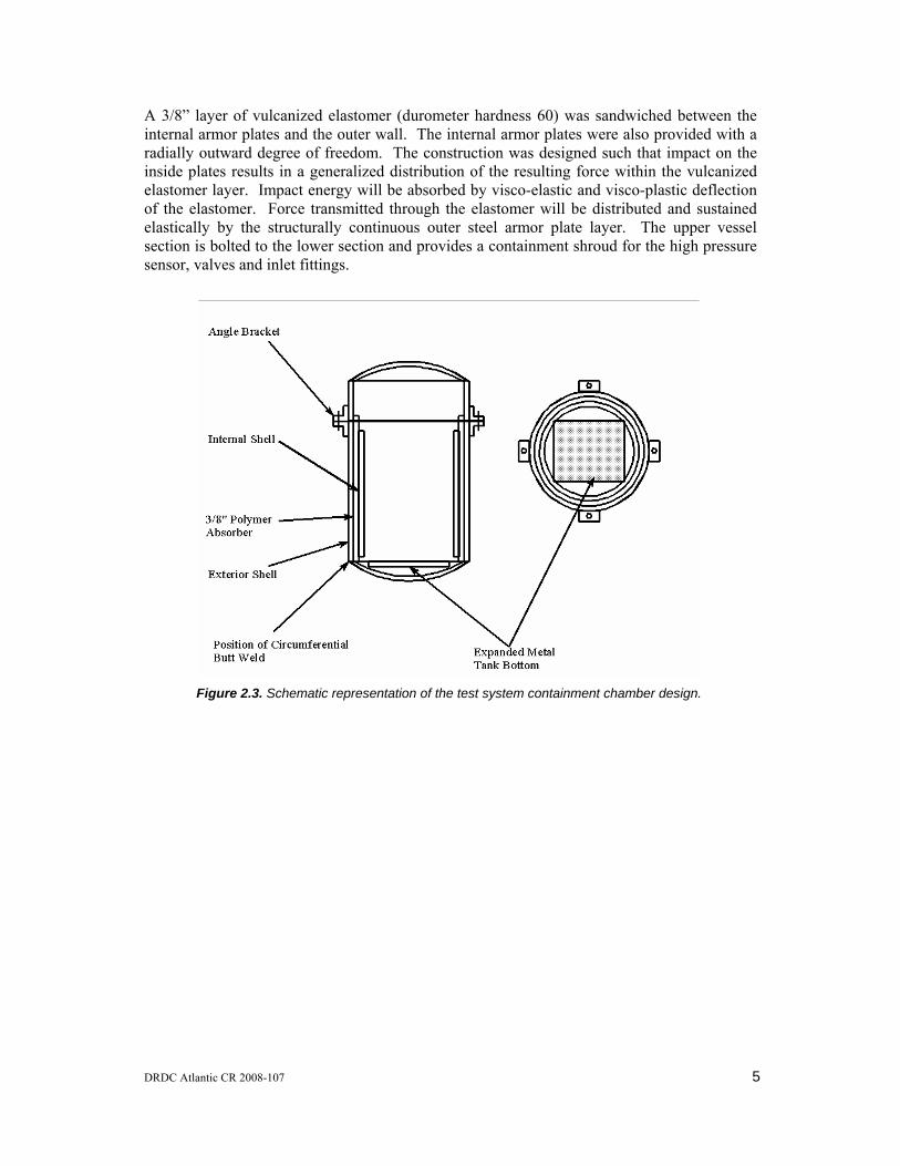
A 3/8” layer of vulcanized elastomer (durometer hardness 60) was sandwiched between the internal armor plates and the outer wall. The internal armor plates were also provided with a radially outward degree of freedom. The construction was designed such that impact on the inside plates results in a generalized distribution of the resulting force within the vulcanized elastomer layer. Impact energy will be absorbed by visco-elastic and visco-plastic deflection of the elastomer. Force transmitted through the elastomer will be distributed and sustained elastically by the structurally continuous outer steel armor plate layer. The upper vessel section is bolted to the lower section and provides a containment shroud for the high pressure sensor, valves and inlet fittings.
Figure 2.3. Schematic representation of the test system containment chamber design.
DRDC Atlantic CR 2008-107 5
3. EXPERIMENTAL PROCEDURES
3.1 Recommended Practice for Conducting a Hydrostatic Test
3.1.1 Valve and Containment Chamber Configuration Set-up
The first step associated with conducting a hydrostatic test is configuring and sealing the component which requires testing (in this case a NAB submarine valve). The instructions for assembling and configuring the valve within the containment chamber are as follows.
Remove the O-ring seals from the valve flange heads, clean the O-ring seat and inspect the seat for any evidence of corrosion pitting or loose debris. Subsequent to inspection and any remediation required, apply a coating of sealing grease to the seat.
Clean and inspect the O-ring for evidence of physical damage or embedded particulate which may affect the high pressure seal. If the O-ring has sustained physical damage replace it. Apply a coating of sealing grease to the O-ring prior to inserting it back into the O-ring head seat.
Clean and inspect the mating valve flange surfaces for evidence of damage.
Prior to attaching the heads to the flanges, ensure that the valve is in the fully open position.
Align the clearance holes in the valve heads with those on the flanges, insert the threaded studs through the clearance holes and hand tighten the stud nuts.
Apply an initial torque to the nuts of approximately 10-15 percent of the magnitude of the final torque. For the eight stud flanges tested as part of this project, the bolt torque sequence recommended is 1,5,3,7,2,6,4,8.
Repeat Step 6 for a bolt torque of approximately 50-60 percent and 100 percent of the magnitude of the final torque.
Repeat Step 7 at 100 percent torque to ensure uniform loading on the studs.
Attach the valve positioning handles to the upper surface of the rectangular valve head.
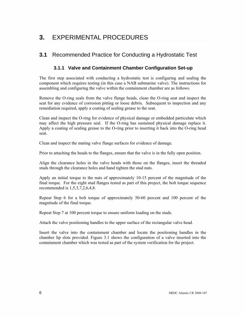
Insert the valve into the containment chamber and locate the positioning handles in the chamber lip slots provided. Figure 3.1 shows the configuration of a valve inserted into the containment chamber which was tested as part of the system verification for the project.
6 DRDC Atlantic CR 2008-107
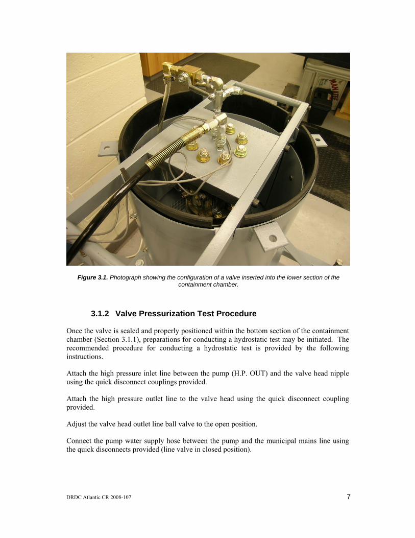
Figure 3.1. Photograph showing the configuration of a valve inserted into the lower section of the containment chamber.
3.1.2 Valve Pressurization Test Procedure
Once the valve is sealed and properly positioned within the bottom section of the containment chamber (Section 3.1.1), preparations for conducting a hydrostatic test may be initiated. The recommended procedure for conducting a hydrostatic test is provided by the following instructions.
Attach the high pressure inlet line between the pump (H.P. OUT) and the valve head nipple using the quick disconnect couplings provided.
Attach the high pressure outlet line to the valve head using the quick disconnect coupling provided.
Adjust the valve head outlet line ball valve to the open position.
Connect the pump water supply hose between the pump and the municipal mains line using the quick disconnects provided (line valve in closed position).
DRDC Atlantic CR 2008-107 7

Connect the compressed air line between the pump and the compressed air source.
Adjust the pump control valve to the “TEST” position and ensure that the regulator is turned to its fully counterclockwise position.
Adjust the H.P. relief valve to the “TEST” position.
Adjust the pump water supply line valve to the open position. Upon opening the water supply valve, water flow should be introduced into the valve to be tested at a pressure consistent with the municipal mains.
Bleed the air from the valve and associated lines by allowing water to flow through the system until there is no evidence of trapped air (in the water flow) at the valve head outlet line.
Once all the air has been bled from the system, adjust the valve head outlet line valve to the closed position.
Position and attach the top section of the containment chamber shell to the lower section at the integral L-brackets using the threaded couplings provided.
Adjust the pump control valve to the “PUMP” position.
Activate the electronic signal conditioning and data acquisition electronics and initiate the acquisition sequence.
Adjust the pressure in the valve to be tested by turning the regulator handle clockwise.
Once the desired pressure profile has been applied to the valve (test completion), adjust the pump control valve to the “TEST” position.
Adjust the water supply valve to the closed position.
Depressurize the system by adjusting the H.P. relief valve to the “H.P. RELIEF” position.
Adjust the regulator to its fully counterclockwise position.
Figure 3.2 shows a photograph of the fully configured system during one of the system verification tests conducted. The photograph shows the functional relationship between the various components (i.e. the containment chamber, the pump, and the data acquisition electronics).
8 DRDC Atlantic CR 2008-107

Figure 3.2. Photograph showing the functional relationship between the containment chamber, the pump, and the data acquisition electronics for a fully configured test.
DRDC Atlantic CR 2008-107 9
4. SYSTEM VERIFICATION TESTS AND RESULTS
Several experiments were conducted to verify that the hydrostatic test system was functioning according to specifications. Experiments were conducted using both the larger (SW226) and smaller (SW604) submarine valves. For each experiment, the valve and chamber was configured with the procedure described in Section 3.1.1. For the large and small valves, the final torque applied to studs was between approximately 120 to 140 ft-lbs and 100 to 120 ft-lbs, respectively. Prior to inserting the valve into the containment chamber, DRDC personnel attached several strain gauges to the exterior surface of the valve at predetermined locations. The signals from the strain gauges were conditioned and, in combination with the internal valve pressure, routed to the data acquisition suite for storage and subsequent post processing.
For each valve tested, the internal valve pressure was increased by ramping to a series of hold positions ranging between approximately 0 psig and 5000 psig using the manual regulator control on the diaphragm pump. In a similar fashion, the internal pressure was decreased from 5000 psig to 0 psig using the manual pressure relief valve included with the pump. At each hold position, the system pressure was observed and monitored for evidence of a pressure drop which is typically associated with a seal leak in one or more of the high pressure system components. For the test conducted to a maximum valve pressure of approximately 5000 psig, neither the large nor small valve tests indicated evidence of a seal leak pressure drop. Figure 4.1 shows the relationship between the internal applied valve pressure and the output from one of the strain gauges adhered to the exterior surface of the valve for valve SW604 (small valve). The graph indicates an approximately linear relationship between internal valve body pressure and material strain. The relationship indicates that the material response was essentially elastic for internal pressure between 0 psig and 5000 psig.
10 DRDC Atlantic CR 2008-107

0
1000
2000
3000
4000
5000
6000
0 200 400 600 800 1000 1200 1400Strain (micro strain)
Pres
sure
(psi
)
Body (Axial)
Body (Circumferential)
Neck (Circumferential)
Figure 4.1. Relationship between internal valve body pressure and material strain for a test conducted
with submarine valve SW403.
DRDC Atlantic CR 2008-107 11
5. SUMMARY AND CONCLUSIONS
A test system for conducting hydrostatic testing of submarine valves has been designed and fabricated. The design consists of two main components, namely, a high pressure valve pressurization circulation loop, and an external ambient pressure external containment chamber. The high pressure circulation loop was designed to apply pressures between 0 psig and 5000 psig in accordance with DRDC’s specified requirement. Applied pressure was generated by the inclusion of a low flow rate diaphragm pump in the circuit. Where possible, commercially available components and fittings were utilized in the fabrication of the high pressure loop. The minimum operating pressure associated with the commercial components included in the system was 7250 psig. Two sets of custom flange heads were also fabricated for sealing the submarine valve flanges based on a previous head design which provided an acceptable seal to approximately 8000 psi. ASME B16.5 indicated that the head design was non-standard with an approximate Class 1500 component rating. For the material and configuration, ASME B16.5 specified a 3705 psig continuos working pressure for the flange heads and, as such should only be employed when fully enclosed within the containment chamber. The exterior (ambient pressure) chamber was designed to contain events including a high pressure water jet (in the case of a “leak before break” type of failure mode) and a kinetic energy impact event from one or more of the components associated with a high pressure flow loop (catastrophic failure of the valve components).
Several experiments were conducted to verify that the hydrostatic test system was functioning according to specifications. Experiments were conducted using both the larger (SW226) and smaller (SW604) submarine valves. For each valve tested, the internal valve pressure was increased by ramping to a series of hold positions ranging between approximately 0 psig and 5000 psig. For the test conducted to a maximum valve pressure of approximately 5000 psig, neither the large nor small valve tests indicated evidence of a seal leak pressure drop. Results generated for valve SW604 (small valve) indicates an approximately linear relationship between internal valve body pressure and material strain (an elastic response) for applied pressure between 0 psig and 5000 psig.
12 DRDC Atlantic CR 2008-107

6. REFERENCES
1. ASTM A-516-1990, “Standard Specification for Pressure Vessel Plates, Carbon Steel, for Moderate and Lower-Temperature Service”, Annual Book of ASTM Standards, Volume 1.04, West Conshohocken, 1999.
2. ASME B16.5-1996, “Pipe Flanges and Flange Fittings – NPS Through NPS 24”, The American Society of Mechanical Engineers, New York, 1998.
3. ASTM A-193-1998, “Standard Specification for Alloy-Steel and Stainless Steel Bolting Materials for High-Temperature Service”, Annual Book of ASTM Standards, Volume 1.01, West Conshohocken, 1999.
DRDC Atlantic CR 2008-107 13

This page intentionally left blank.
14 DRDC Atlantic CR 2008-107

DRDC Atlantic CR 2008-107 15
Distribution list
DRDC Atlantic CR 2008-107
Internal Distribution 2 Yueping Wang: 1 CD, 1 hard copy
1 Wade Temple
1 John Porter
1 H/DL(A)
1 H/DL(P)
5 DRDC Atlantic Library File Copies: 4 CDs, 1 hard copy
Total internal copies: 11
External Distribution 2 LCdr. Christian Brown: 1 CD, 1 hard copy
DMEPM(SM) 4-2
NDHQ/Louis St-Laurent Building
555 Boul de la Carriere
Hull, QC K1A 0K2
1 Mr. Peter Heppleston
DMEPM(SM) 4-4-4
NDHQ/Louis St-Laurent Building
555 Boul de la Carriere
Hull, QC K1A 0K2
1 MARLANT HQ/ N42 FTA/SSO Subs, 1 hard copy
CFB Halifax, Bldg D-200
PO Box 99000 Stn Forces
Halifax, NS B3K 5X5
1 MARPAC HQ/ JTF(P)HQ DCOS FTA/SSO subs, 1 hard copy
CFB Esquimalt
PO BOX 17000 Stn Forces
Victoria, BC, V9A 7N2
1 NDHQ/DRDC/DRDKIM 3
1 Library & Archives Canada
Attention: Military Archivist, Government Records Branch
Total external copies: 7
Total copies: 18

This page intentionally left blank.
16 DRDC Atlantic CR 2008-107

DOCUMENT CONTROL DATA (Security classification of title, body of abstract and indexing annotation must be entered when the overall document is classified)
1. ORIGINATOR (the name and address of the organization preparing the document. Organizations for whom the document was prepared, e.g. Centre sponsoring a contractor's report, or tasking agency, are entered in section 8.)
FACTS Engineering Inc. PO Box 20039 Halifax, Nova Scotia B3R 2K9
2. SECURITY CLASSIFICATION (overall security classification of the document
including special warning terms if applicable).
UNCLASSIFIED
3. TITLE (the complete document title as indicated on the title page. Its classification should be indicated by the appropriate abbreviation (S,C,R or U) in parentheses after the title)
Design and Fabrication of a Hydrostatic Testing System for Submarine Nickel Aluminum Bronze Valves
4. AUTHORS (Last name, first name, middle initial. If military, show rank, e.g. Doe, Maj. John E.)
Ken KarisAllen
5. DATE OF PUBLICATION (month and year of publication of document)
June 2008
6a. NO. OF PAGES (total containing information Include Annexes, Appendices, etc).
28
6b. NO. OF REFS (total cited in document)
3
7. DESCRIPTIVE NOTES (the category of the document, e.g. technical report, technical note or memorandum. If appropriate, enter the type of
report, e.g. interim, progress, summary, annual or final. Give the inclusive dates when a specific reporting period is covered).
CONTRACT REPORT
8. SPONSORING ACTIVITY (the name of the department project office or laboratory sponsoring the research and development. Include address).
Defence R&D Canada - Atlantic PO Box 1012 Dartmouth, NS, Canada B2Y 3Z7
9a. PROJECT OR GRANT NO. (if appropriate, the applicable research
and development project or grant number under which the document was written. Please specify whether project or grant).
Sub SLA – 20ed03-02
9b. CONTRACT NO. (if appropriate, the applicable number under which the document was written).
W7707-078023/001/HAL
10a ORIGINATOR'S DOCUMENT NUMBER (the official document
number by which the document is identified by the originating activity. This number must be unique to this document.)
DRDC Atlantic CR 2008-107
10b OTHER DOCUMENT NOs. (Any other numbers which may be assigned this document either by the originator or by the sponsor.)
11. DOCUMENT AVAILABILITY (any limitations on further dissemination of the document, other than those imposed by security classification)
( X ) Unlimited distribution ( ) Defence departments and defence contractors; further distribution only as approved ( ) Defence departments and Canadian defence contractors; further distribution only as approved ( ) Government departments and agencies; further distribution only as approved ( ) Defence departments; further distribution only as approved ( ) Other (please specify):
12. DOCUMENT ANNOUNCEMENT (any limitation to the bibliographic announcement of this document. This will normally correspond to the Document Availability (11). However, where further distribution (beyond the audience specified in (11) is possible, a wider announcement audience may be selected).

13. ABSTRACT (a brief and factual summary of the document. It may also appear elsewhere in the body of the document itself. It is
highly desirable that the abstract of classified documents be unclassified. Each paragraph of the abstract shall begin with an indication of the security classification of the information in the paragraph (unless the document itself is unclassified) represented as (S), (C), (R), or (U). It is not necessary to include here abstracts in both official languages unless the text is bilingual).
A test system for conducting hydrostatic testing of submarine valves has been designed and fabricated. The design consists of two main components, namely, a high pressure valve pressurization circulation loop, and an external ambient pressure external containment chamber. The high pressure circulation loop was designed to apply pressures between 0 psig and 5000 psig in accordance with DRDC’s specified requirement. The exterior (ambient pressure) chamber was designed to contain events including a high pressure water jet (in the case of a “leak before break” type of failure mode) and a kinetic energy impact event from one or more of the components associated with a high pressure flow loop (catastrophic failure of the valve components). The experiments conducted have verified that the hydrostatic test system was functioning according to specifications.
14. KEYWORDS, DESCRIPTORS or IDENTIFIERS (technically meaningful terms or short phrases that characterize a
document and could be helpful in cataloguing the document. They should be selected so that no security classification is required. Identifiers, such as equipment model designation, trade name, military project code name, geographic location may also be included. If possible keywords should be selected from a published thesaurus. e.g. Thesaurus of Engineering and Scientific Terms (TEST) and that thesaurus-identified. If it not possible to select indexing terms which are Unclassified, the classification of each should be indicated as with the title). Hydrostatic testing system, Nickel aluminum bronze, valve, failure mode

This page intentionally left blank.
