design and fabrication of spokeless bicycle · design and fabrication of spokeless bicycle 1 design...
TRANSCRIPT

International Journal of Mechanical And Production Engineering, ISSN: 2320-2092, Volume- 3, Issue-9, Sept.-2015
Design And Fabrication Of Spokeless Bicycle 1
DESIGN AND FABRICATION OF SPOKELESS BICYCLE
1K. AKASH, 2CH. ADITYA, 3K. CHANDRA SEKHAR
1B.Tech (Mechanical), 2B.Tech (Mechanical), 3Asst. Prof. (Mechanical), CVRCOE. E-mail: [email protected], 2 [email protected], [email protected]
Abstract— This spokeless bicycle system for design and fabrication of a bicycle that does not have spokes within the wheels. This bicycle includes a frame having a seat structure and handle bars, a rear bracket having rear bearings within that concentrically engages a rear wheel, a front bracket having front bearings within that pivotingly engages a front wheel which is poked, and a drive train that engages the rear wheel for driving the rear wheel. The rear rim of the rear wheel includes a rear groove that receives the plurality of rear bearings. The rear rim of the rear wheel includes a rear gear that is engaged by a drive sprocket from the drive train. The front rim of the front wheel being spoked receives the plurality of front bearings. Thus,providing a mechanical setup less in weight, sturdy in design which is cheap and ecofriendly. Index Terms— Driving hub, Milling, Oxy acetylene welding, TIG welding. I. INTRODUCTION Bicycles are one of the most ubiquitous forms of transportation in the world. Much of the world uses bicycles as a primary form of daily transportation. What would take several hours of travel on foot becomes faster and more efficient on two wheels. Some cyclists take trips across entire states or cross-country solely on a bicycle. Reaching speeds of 15 miles or 30 km an hour is achievable by even beginning cyclists, while more experienced riders can reach speeds equivalent to automobile travel. "Century riders" travel 100 miles or more within a typical day. Not to be constrained by simple transportation, bicycles (stationary and otherwise) have helped people become healthier by losing excess weight and improving cardiovascular fitness. Conventional bicycles With Wheels that have spokes is that the user constantly has to maintain the tension upon the spokes especially during rough riding conditions. If the user does not maintain the tension upon the spokes the Wheel Will not provide the desired performance for the user. Bicycles that use Wheels With spokes are also dangerous in the respect that clothing and feet often times are caught Within the spokes sometimes leading to injury of the rider. Elliot (US. Pat. No. 5,626,354) discloses a bicycle transmission. Elliott specifically teaches a continuously variable friction drive transmission by driving the rear bicycle Wheel by frictional engagement With a rotating rim driver. While these devices may be suitable for the particular purpose to which they address, they are not as suitable for providing a bicycle that does not have spokes within the wheels. Conventional bicycle devices require the utilization of wheels with a plurality of spokes which are undesirable. In these respects, the spokeless bicycle system according to the present invention substantially departs from the conventional concepts and designs of the prior art, and in so doing provides an apparatus
primarily developed for the purpose of providing a bicycle that does not have spokes within the wheels. II. DESIGN A. Design of rear wheel The spoke-less wheel is the main drive that is to be rotated by the pinion. For this purpose teeth were made on the inner circumference of the wheel. The spacing between the holes made is the same as the pitch of the pinion gear. The perfect meshing is made so that the gears move smoothly and helps in driving so that the drive is smooth. For this purpose mild steel was used density being 7850kg/m3 and Young’s modulus E = 210GPA
Outer Diameter (OD) =0.4064m Inner Diameter (ID) =0.36836m Thickness =0.0254m Weight =4.62kgs
Here we use 200 full depth involute for weigh bearing and less friction. Minimum number of teeth to avoid interference on pinion is 18.
Assuming, minimum number of teeth =32 D1 = Inner diameter of Rack = 0.3683m D2 = Diameter of Pinion = 0.1016m As we know, D1/D2 = T1/T2 0.3683/0.1016 = T1/32 T1 = 116 Module (m) = D/T = 0.4064/116=3.175X10-3
Table I: specifications of pinion

International Journal of Mechanical And Production Engineering, ISSN: 2320-2092, Volume- 3, Issue-9, Sept.-2015
Design And Fabrication Of Spokeless Bicycle 2
B. Speed calculations Average road bike speed is 18-22 mph. Assuming V =7.2km/hr
= 60 X7.2 /3.14X0.4064= 94 Number of teeth on pedal gear (rear sprocket) = 18 Number of teeth on pedal gear (front sprocket) = 44 Pedalling Power = Force on pedals X Speed of pedal = 80X7200/3600=160kgm/s
=1569.063watts C. Torque calculations Force is applied to pedals. If random man is standing on the pedal and the pedal is parallel to the flat road, then he’s exerting 80kg of force downward on the pedal. Really, you cannot apply your full load into the pedals at all times and the average force will be less, but we’re simplifying. Also, if the pedal is not parallel, then only a trig ratio of the force on the pedal is producing rotation. Weight of the man = 80kg Torque on crank = Force X perpendicular distance Crank length = 0.182m Torque on crank = 80 X (0.182/2) = 7.3152 kgm Torque applied to rear gear is torque on front gear times inverse ratio of front and rear gears. Torque on rear gear = torque on force X (R/F)
= 7.3152 X (18/44) = 3kgm The torque delivered to the rear gear is about 41% of the front chainring while rotational velocity of the freewheel is 1/41% = 243%. Force applied to the road with 0.4064m tire is
= Chainring torque/Radius of rim =3/0.2032 =14.763kg
D. Moment of pedal Here pedal length is 0.1651m Assuming, a random man is standing on the pedal the force acting on pedal =80kg. Horizontal moment on pedal =80 x 0.1651= 13.208kgm. Vertical moment on pedal =80x 0=0kgm. III. FABRICATION OF SPOKE-LESS WHEEL
During the fabrication of this cycle we underwent many fabrication processes at different stages. Each of these fabrication processes are discussed below. A. Cutting The first and main component we fabricated was our spoke-less wheel by the process of oxy-fuel cutting by cutting mildsteel sheet of thickness 1inch. The oxy-fuel cutting process is the most widely applied industrial thermal cutting process because it can cut thicknesses from 0.5mm to 250mm, the equipment is low cost and can be used manually or mechanised.
There are several fuel gas and nozzle design options that can significantly enhance performance in terms of cut quality and cutting speed.
Fig.1 Oxy acetylene cutting process.
The cutting process is illustrated in Fig. 1. Basically, a mixture of oxygen and the fuel gas is used to preheat the metal to its 'ignition' temperature which, for steel, is 700°C - 900°C (bright red heat) but well below its melting point. A jet of pure oxygen is then directed into the preheated area instigating a vigorous exothermic chemical reaction between the oxygen and the metal to form iron oxide or slag. The oxygen jet blows away the slag enabling the jet to pierce through the material and continue to cut through the material. Thus, we a 16 inch diameter circular plate first and then a ring of internal diameter 14.5 inch. The material detail and dimensions of the pipe which we cut are as follows:
Material: Mild Steel Ring thickness: 1.5 inch Ring Outer diameter: 16 inch Ring Inner diameter: 14.5 inch.
Fig.2: Ring after cutting
The wheel was not completely flat. Slight error of around 5mm was existing in the wheel. B. Turning: This operation is one of the most basic machining processes. That is, the part is rotated while a single
International Journal of Mechanical And Production Engineering, ISSN: 2320-2092, Volume- 3, Issue-9, Sept.-2015
Design And Fabrication Of Spokeless Bicycle 3
point cutting tool is moved parallel to the axis of rotation. Turning can be done on the external surface of the part as well as internally (boring). The starting material is generally a work piece generated by other processes such as casting, forging, extrusion, or drawing. C. Gear Cutting: Spur may be cut or ground on a milling machine jig grinder utilizing a numbered gear cutter, and any indexing head or rotary table. The number of the gear cutter is determined by the tooth count of the gear to be cut. To machine a helical gear on a manual machine, a true indexing fixture must be used. Indexing fixtures can disengage the drive worm, and be attached via an external gear train to the machine table's handle (like a power feed). It then operates similarly to a carriage on a lathe. As the table moves on the X axis, the fixture will rotate in a fixed ratio with the table. The indexing fixture itself receives its name from the original purpose of the tool: moving the table in precise, fixed increments. If the indexing worm is not disengaged from the table, one can move the table in a highly controlled fashion via the indexing plate to produce linear movement of great precision (such as a Vernier scale). There are a few different types of cutters used when creating gears. One is a rack shaper. These are straight and move in a direction tangent to the gear, while the gear is fixed. They have six to twelve teeth and eventually have to be moved back to the starting point to begin another cut. A popular way to build gears is by form cutting. This is done by taking a blank gear and rotating a cutter, with the desired tooth pattern, around its periphery. This ensures that the gear will fit when the operation is finished.
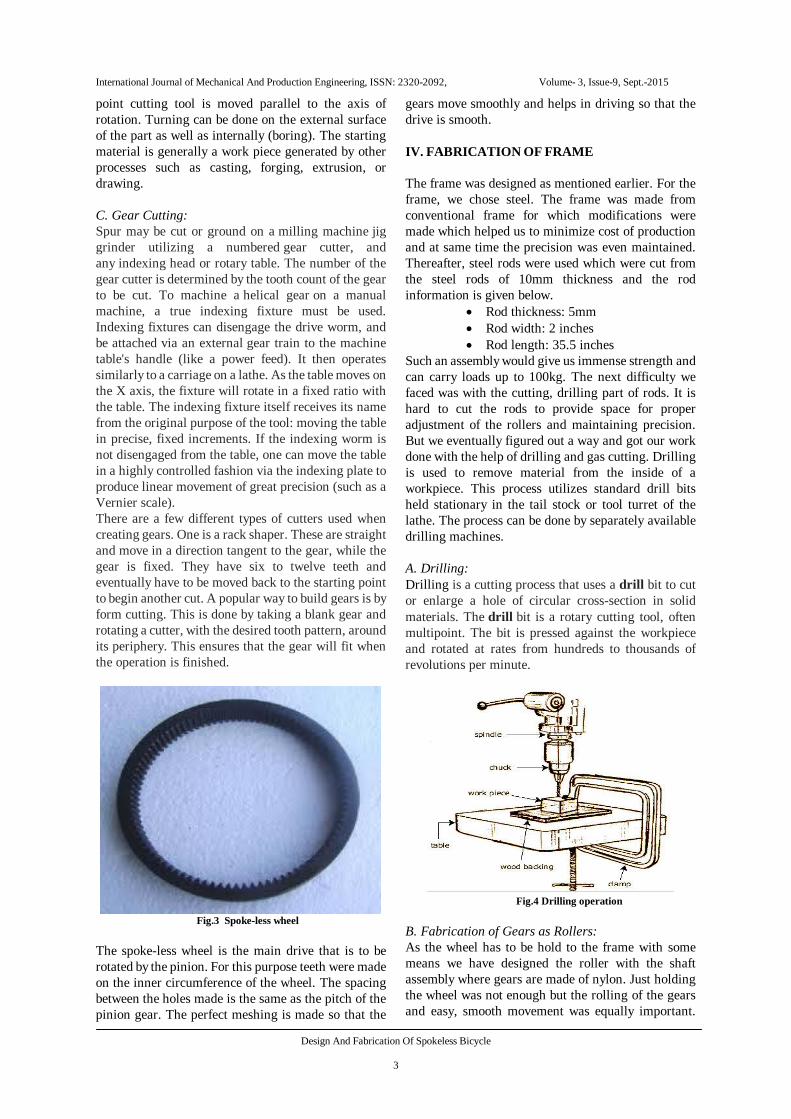
Fig.3 Spoke-less wheel
The spoke-less wheel is the main drive that is to be rotated by the pinion. For this purpose teeth were made on the inner circumference of the wheel. The spacing between the holes made is the same as the pitch of the pinion gear. The perfect meshing is made so that the
gears move smoothly and helps in driving so that the drive is smooth. IV. FABRICATION OF FRAME The frame was designed as mentioned earlier. For the frame, we chose steel. The frame was made from conventional frame for which modifications were made which helped us to minimize cost of production and at same time the precision was even maintained. Thereafter, steel rods were used which were cut from the steel rods of 10mm thickness and the rod information is given below.
Rod thickness: 5mm Rod width: 2 inches Rod length: 35.5 inches
Such an assembly would give us immense strength and can carry loads up to 100kg. The next difficulty we faced was with the cutting, drilling part of rods. It is hard to cut the rods to provide space for proper adjustment of the rollers and maintaining precision. But we eventually figured out a way and got our work done with the help of drilling and gas cutting. Drilling is used to remove material from the inside of a workpiece. This process utilizes standard drill bits held stationary in the tail stock or tool turret of the lathe. The process can be done by separately available drilling machines. A. Drilling: Drilling is a cutting process that uses a drill bit to cut or enlarge a hole of circular cross-section in solid materials. The drill bit is a rotary cutting tool, often multipoint. The bit is pressed against the workpiece and rotated at rates from hundreds to thousands of revolutions per minute.
Fig.4 Drilling operation
B. Fabrication of Gears as Rollers: As the wheel has to be hold to the frame with some means we have designed the roller with the shaft assembly where gears are made of nylon. Just holding the wheel was not enough but the rolling of the gears and easy, smooth movement was equally important.

International Journal of Mechanical And Production Engineering, ISSN: 2320-2092, Volume- 3, Issue-9, Sept.-2015
Design And Fabrication Of Spokeless Bicycle 4
Thus gear and shaft assembly was made by turning and milling operations for gear tooth cutting and turning using lathe and milling machine. Bearings here play major role as they allow free movement of the roller on the shaft at the same time maintain the perfect alignment. There are even steel metal metal sheets arranged beside the gears for perfect positioning of the gear and allowing no any misalignment of the wheel. The following figure shows a finished gear and shaft assembly attached in the cycle frame.
Fig.5 Finished gear and shaft assembly
C. Operations on Lathe: We brought solid nylon shafts of 50mm diameter. These nylon shafts were then turned and grooved on the lathe. The required dimensions after machining were as follows:
Outer diameter: 40mm Inner diameter: 12mm Semi-circular groove: 35mm
The nylon shaft so designed was to be attached with steel cups on their un-machined faces. Thus the faces were again turned on the lathes so as to accommodate these steel cups, one on both the faces. The required components for the assembly of the nylon shafts are as shown in the following picture.
Fig.6 Shaft assembly and steel cups
The final assembly of the cone and cup inserted with roller balls to produce smooth motion of nylon shafts is as shown in the following figure.
Fig.7 The assembly for holding shafts
D. Fabrication of driving hub: The driving hub of a normal bicycle is held to the wheel using spokes. One side of this hub is mounted with a free wheel. A free wheel is a gear with roller balls inserted inside its casing. Because of this arrangement, the gear imparts forward motion only. When peddled in reverse, the gear doesn’t impart any motion to the cycle. This is a very important arrangement because if at all it is not so, while peddling in reverse, the cycle will also start moving in reverse. In our project, there was a need for another gear, which would drive the spoke-less wheel. This gear would mesh with the spoke-less wheel and will impart the motion to the cycle. To do this, we had to put this gear with the driving hub only.
Fig.8 Conventional driving hub
The problem was how to fix this new gear and attach it to the driving hub. Because, both the ends of the hub were bigger than the inner diameter of the driving gear while the inner spine of the hub was very thin and smaller than the inner radius of the gear. So, the outer rings of the hub were turned on lathe to remove the obstructing material. Next difficulty was to fix the driving pinion on the thin spine of hub, so that it

International Journal of Mechanical And Production Engineering, ISSN: 2320-2092, Volume- 3, Issue-9, Sept.-2015
Design And Fabrication Of Spokeless Bicycle 5
correctly meshes with the spoke-less wheel. To do this, we took two M.S. circular plates of 3mm thickness. Then, it was machined on lathe such that its outer diameter matches the inner diameter of driving gear, and the inner diameter of the plate matches the outer diameter of hub’s spine. Now, we got the plates split into two parts from the centre. The slit was so made that the material loss should not be more than 3mm. The material loss had to be considered because more loss in material would loosen the grip between the driving hub and the gear. The two separated parted of the circular disc were then fitted on the hub and inside the gear from both the sides. These parts were welded from the slitted region. This process gave a solid gear like structure. This was now moved on to the thin spin of driving hub and checked for the spot where it meshed effectively with the drilled wheel. After marking the spot, the whole assembly of driving gear and the welded plates were welded again to the spine of the driving hub. This made the driving gear a part of the driving hub.
E. Tig Welding Gas tungsten arc welding (GTAW), also known as tungsten inert gas (TIG) welding, is an arc welding process that uses a non-consumable tungsten electrode to produce the weld. The weld area is protected from atmospheric contamination by an inert shielding gas (argon or helium), and a filler metal is normally used, though some welds, known as autogenously welds, do not require it. A constant-current welding power supply produces energy which is conducted across the arc through a column of highly ionized gas and metal vapors known as plasma.to produce the weld. The weld area is protected from atmospheric contamination by an inert shielding gas (argon or helium), and a filler metal is normally used, though some welds, known as autogenously welds, do not require it. A constant-current welding power supply produces energy which is conducted across the arc through a column of highly ionized gas and metal vapors known as plasma.
Fig.9 Tig welding apparatus
The hub that is generally used in normal cycle has shown below is slightly modified. To one end of this hub, a free wheel is taken and fixed. To the other end for the pinion to fix permanently, two M S plates are taken of 5mm thick were taken. A hole that is exactly of hub diameter is drilled into the plates and was slitted into pieces. Thus these plates act as filling material and these were assembled with hub by supporting pinion and were welded using TIG welding. The excess material that is not required on the hub was removed on lathe by turning process. After the fabrication of the shaft it looks as shown below.
Fig.10 Driving hub designed and attached
F. Clamping: The wobbling of driving hub in horizontal and vertical direction should be restricted for the perfect meshing of driving pinion and holes of the spoke-less wheel. So the driving will be perfect and smooth. In order to achieve this, the rectangular MS plates of following dimensions were taken:
Plate thickness: 5mm Plate length: 320mm Plate width: 25mm Holes drilled: 10mm
These plates were drilled and marked at the spots from where the holes to be extended. These plates were tightly clamped from both sides using the shafts. The same procedure was repeated for the other end of the plate. The straightness of the plates and their arrangement was checked for proper alignment of gear and wheel. Thereafter, the hole was extended for the movement of the roller so that the alignment is free and allows free movement of gear. These extensions were made using gas cutting.
Fig.11 Rods used in frame design.

International Journal of Mechanical And Production Engineering, ISSN: 2320-2092, Volume- 3, Issue-9, Sept.-2015
Design And Fabrication Of Spokeless Bicycle 6
V. ASSEMBLY OF THE CYCLE Assembly plays a vital role cause the final drive is only possible if the assembly of all the parts are done well. The different parts which were to be assembled were also an assembly of many small parts. For example: gear and shaft assembly. Each of the shafts assembly are made out by assembling steel cups, roller balls and a threaded shaft to hold all these. Two such shaft assemblies are prepared as already mentioned earlier. For the assembly of nylon shafts, both the frames were clamped together and three slots were made by drilling multiple holes on height 10mm and width 50mm. These multiple holes were then filled to make smooth slots. The slots were so made that they were separated by 120 degrees angle from each other. This particular orientation was needed for an efficient holding from geometry point of view. After inserting the shaft assembly, the spoke-less wheel was mounted around these three shafts. The second part to be thought after was the driving hub. The driving hub had two gears and so, it needed clearance for insertion from one side. So, one of the two frames which was on the side of the pedals had to be cut out. The cavity had also to be made in order to give room for the chain to move freely on the free-wheel. Firstly, the chain was set with no any assembly problems so that the alignment of wheel doesn’t get affected. If not it would let to problems like disturbances in the alignment of the wheel like the misalignment from the driving gear causing the failure of the gear drive. Then the driving hub had to be clamped to arrest its vibrations completely. Hence shaft and gear assembly hold the driving hub tightly with the frame. The final assembly was to be done for the free-wheel of driving hub and the pedaling wheel by a chain. This assembly was done by increasing the shaft length of the pedaling shaft. The assembled cycle including all the components is as shown in the following figure.
Fig 12 Assembled Spoke-less Bicycle
CONCLUSION AND FUTURE SCOPE The spoke-less cycle was aimed at reducing weight of the cycle by replacing the conventional hub and the spokes and providing more space for utilization. And even overall design being sturdy is even compact and simple with no braking system required as the pedaling stops so does the cycle. This cycle being self braking type can be used on slopes as slipping can be avoided. Due it’s rim being mild steel is weigh bearing capacity is even higher compared to conventional cycles. Future scope includes motorizing the cycle which is quite possible due to the space availability and even super alloys can further reduce weight and due removal of spokes we can go for foldable bike models easily. REFERENCES
[1] http://www.analyticcycling.com/PedalModelConcept_Pa
ge.html [2] http://waterloobikes.ca/2011/01/21/bicycle-transmission-phy
sics/ [3] Bicycle Design: An Illustrated History By Tony Hadland,
Hans-Erhard Lessing, Nick Clayton, Gary W. Sanderson [4] Electric Bicycles: A Guide to Design and Use By William C.
Morchin, Henry Oman. [5] A Textbook of Machine Design by R.S.KHURMI AND
J.K.GUPTA: Machine Design.