design and implementation of microcontroller … describe research work andmuch more has been...
TRANSCRIPT

© 2013. Murad Ali. This is a research/review paper, distributed under the terms of the Creative Commons Attribution-Noncommercial 3.0 Unported License http://creativecommons.org/licenses/by-nc/3.0/), permitting all non commercial use, distribution, and reproduction in any medium, provided the original work is properly cited.
Global Journal of Researches in Engineering Electrical and Electronics Engineering Volume 13 Issue 2 Version 1.0 Year 2013 Type: Double Blind Peer Reviewed International Research Journal Publisher: Global Journals Inc. (USA) Online ISSN: 2249-4596 & Print ISSN: 0975-5861
Design and Implementation of Microcontroller-Based Controlling of Power Factor Using Capacitor Banks with Load Monitoring
By Murad Ali University of Wah
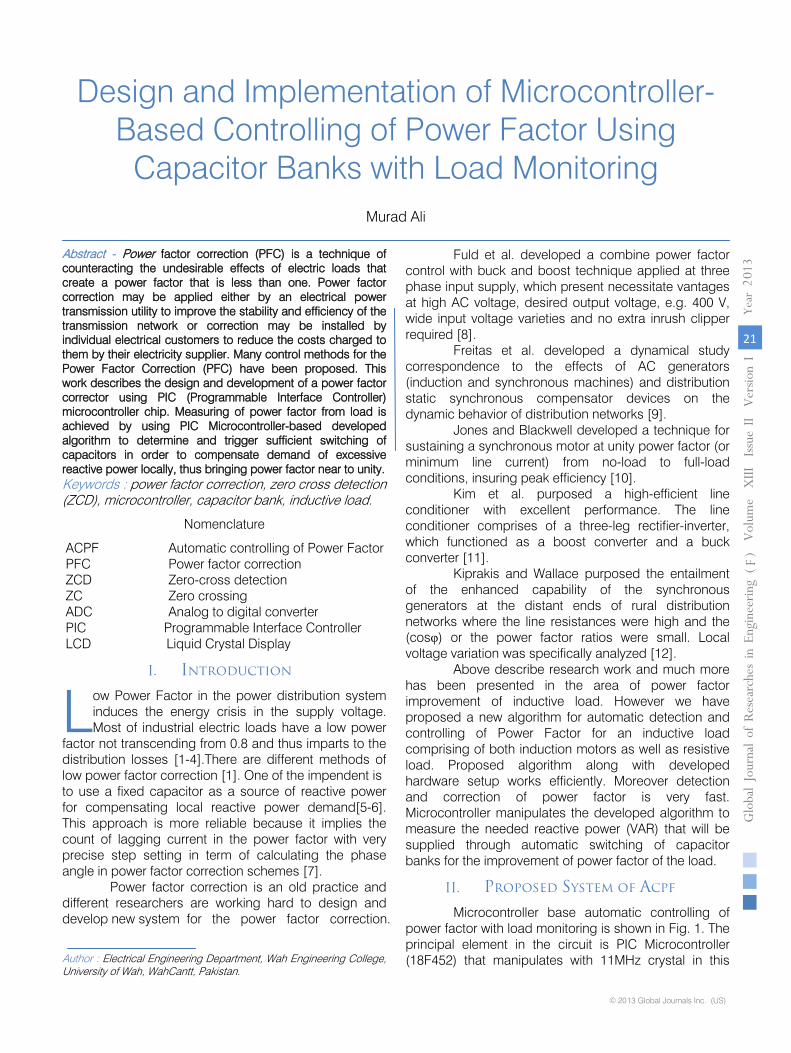
Abstract - Power factor correction (PFC) is a technique of counteracting the undesirable effects of electric loads that create a power factor that is less than one. Power factor correction may be applied either by an electrical power transmission utility to improve the stability and efficiency of the transmission network or correction may be installed by individual electrical customers to reduce the costs charged to them by their electricity supplier. Many control methods for the Power Factor Correction (PFC) have been proposed. This work describes the design and development of a power factor corrector using PIC (Programmable Interface Controller) microcontroller chip. Measuring of power factor from load is achieved by using PIC Microcontroller-based developed algorithm to determine and trigger sufficient switching of capacitors in order to compensate demand of excessive reactive power locally, thus bringing power factor near to unity.
Keywords : power factor correction, zero cross detection (ZCD), microcontroller, capacitor bank, inductive load.
GJRE-F Classification : FOR Code: 090607, 090699
Design and Implementation of Microcontroller-Based Controlling of Power Factor Using Capacitor Banks with Load Monitoring
Strictly as per the compliance and regulations of :
Design and Implementation of Microcontroller-Based Controlling of Power Factor Using
Capacitor Banks with Load Monitoring Murad Ali
Abstract - Power factor correction (PFC) is a technique of counteracting the undesirable effects of electric loads that create a power factor that is less than one. Power factor correction may be applied either by an electrical power transmission utility to improve the stability and efficiency of the transmission network or correction may be installed by individual electrical customers to reduce the costs charged to them by their electricity supplier. Many control methods for the Power Factor Correction (PFC) have been proposed. This work describes the design and development of a power factor corrector using PIC (Programmable Interface Controller) microcontroller chip. Measuring of power factor from load is achieved by using PIC Microcontroller-based developed algorithm to determine and trigger sufficient switching of capacitors in order to compensate demand of excessive reactive power locally, thus bringing power factor near to unity.
Nomenclature
ACPF Automatic controlling of Power Factor PFC Power factor correction ZCD Zero-cross detection ZC Zero crossing ADC Analog to digital converter PIC Programmable Interface Controller LCD Liquid Crystal Display
I. Introduction
ow Power Factor in the power distribution system induces the energy crisis in the supply voltage. Most of industrial electric loads have a low power
factor not transcending from 0.8 and thus imparts to the distribution losses [1-4].There are different methods of low power factor correction [1]. One of the impendent is to use a fixed capacitor as a source of reactive power for compensating local reactive power demand[5-6]. This approach is more reliable because it implies the count of lagging current in the power factor with very precise step setting in term of calculating the phase angle in power factor correction schemes [7].
Power factor correction is an old practice and different researchers are working hard to design and develop new system for the power factor correction. Author : Electrical Engineering Department, Wah Engineering College, University of Wah, WahCantt, Pakistan.
Fuld et al. developed a combine power factor control with buck and boost technique applied at three phase input supply, which present necessitate vantages at high AC voltage, desired output voltage, e.g. 400 V, wide input voltage varieties and no extra inrush clipper required [8].
Freitas et al. developed a dynamical study correspondence to the effects of AC generators (induction and synchronous machines) and distribution static synchronous compensator devices on the dynamic behavior of distribution networks [9].
Jones and Blackwell developed a technique for sustaining a synchronous motor at unity power factor (or minimum line current) from no-load to full-load conditions, insuring peak efficiency [10].
Kim et al. purposed a high-efficient line conditioner with excellent performance. The line conditioner comprises of a three-leg rectifier-inverter, which functioned as a boost converter and a buck converter [11].
Kiprakis and Wallace purposed the entailment of the enhanced capability of the synchronous generators at the distant ends of rural distribution networks where the line resistances were high and the (cosφ) or the power factor ratios were small. Local voltage variation was specifically analyzed [12].
Above describe research work and much more has been presented in the area of power factor improvement of inductive load. However we have proposed a new algorithm for automatic detection and controlling of Power Factor for an inductive load comprising of both induction motors as well as resistive load. Proposed algorithm along with developed hardware setup works efficiently. Moreover detection and correction of power factor is very fast. Microcontroller manipulates the developed algorithm to measure the needed reactive power (VAR) that will be supplied through automatic switching of capacitor banks for the improvement of power factor of the load.
II. Proposed System of Acpf
Microcontroller base automatic controlling of power factor with load monitoring is shown in Fig. 1. The principal element in the circuit is PIC Microcontroller (18F452) that manipulates with 11MHz crystal in this
L Globa
l Jo
urna
l of R
esea
rche
s in E
nginee
ring
Volum
e X
III Issue
II V
ersion
I
21
()
Year
013
2F
© 2013 Global Journals Inc. (US)
Keywords : power factor correction, zero cross detection (ZCD), microcontroller, capacitor bank, inductive load.
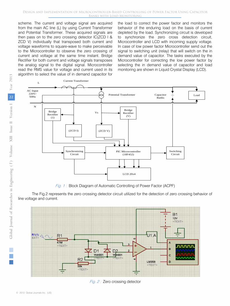
scheme. The current and voltage signal are acquired from the main AC line (L) by using Current Transformer and Potential Transformer. These acquired signals are then pass on to the zero crossing detector IC(ZCD I & ZCD V) individually that transposed both current and voltage waveforms to square-wave to make perceivable to the Microcontroller to observe the zero crossing of current and voltage at the same time instant. Bridge Rectifier for both current and voltage signals transposes the analog signal to the digital signal. Microcontroller read the RMS value for voltage and current used in its algorithm to select the value of in demand capacitor for
the load to correct the power factor and monitors the behavior of the enduring load on the basis of current depleted by the load. Synchronizing circuit is developed to synchronize the zero cross detection circuit, Microcontroller and LCD with incoming supply voltage. In case of low power factor Microcontroller send out the signal to switching unit (relay) that will switch on the in demand value of capacitor. The tasks executed by the Microcontroller for correcting the low power factor by selecting the in demand value of capacitor and load monitoring are shown in Liquid Crystal Display (LCD).
Bridge Rectifier
(V)
(ZCD I)
Switching Circuit
PIC Microcontroller(18F452)
LCD 20x4
(ZCD V)
Bridge Rectifier
(1)
Synchronizing Circuit
Load
L
AC Input220V/50Hz
N
Current Transformer
Potential Transformer Capacitor Banks
Vs
Fig. 1 : Block Diagram of Automatic Controlling of Power Factor (ACPF)
Fig. 2 : Zero crossing detector
Design and Implementation of Microcontroller-Based Controlling of Power Factor Using Capacitor Banks with Load Monitoring
Globa
l Jo
urna
l of
Resea
rche
s in E
nginee
ring
Volum
e X
III Issue
II V
ersion
I
22
()
Year
013
2F
© 2013 Global Journals Inc. (US)
The Fig.2 represents the zero crossing detector circuit utilized for the detection of zero crossing behavior of line voltage and current.

Fig. 3 : Zero crossing detector circuit output
III. Microcontroller Algorithm Scheme
Microcontroller pretends as brain of the
Automatic Controlling of Power Factor using Capacitor Banks with Load Monitoring circuit. For the analysis of voltage and current signals, Microcontroller through microcontroller’s capture module ccp1(for voltage ZC) and ccp2(for current ZC), measure the phase delay between the voltage and current square-waves yielded by the zero crossing detector IC. Microcontroller observes the rising edge of the square-waves of both the signals at same time instant. The time lag evaluated by the Microcontroller is in terms of power factor of the enduring load. After the evaluation of power factor of the load, the RMS value of current and voltage signals is read by the Microcontroller. The low power factor included with current and voltage signals are corrected in the algorithm of the Microcontroller. Microcontroller automatically select the in demand value of capacitor to amend the power factor of the load to desired value. The instructions of the Microcontroller monitor the behavior of the running load on the basis of current depleted by the load and the results were shown on LCD.
Fig. 4 shows the flow chart of the proposed automatic power factor controlling and load monitoring of the load. In the flow chart, the first step is about the initializing the ACPF circuit. Microcontroller measures the line voltage Vrms an Irms through ADC pins (AN0 and AN1) on real time basis. The voltage and current signals which have been converted into square waves after zero crossing are provided to Microcontroller input pins (RC1 and RC2) that are fundamentally the input of capture module of the Microcontroller. If the zero crossing of
voltage and current signals acquired by the Microcontroller points out that V and I signals are not in phase and power factor of load is less then set referenced value of 0.9 lagging then Microcontroller instructs for switching action to involve the required value of capacitor to counterbalance the power factor of running load through developed Microcontroller algorithm to set reference value. Microcontroller does not execute any action if both the voltage and current square-waves provided to capture module of the Microcontroller’s pin are in phase or the measured power factor is 0.9 set as referenced value.LCD displayed the measured values of low power factor, corrected power factor, required value of capacitor to correct the power factor.
Design and Implementation of Microcontroller-Based Controlling of Power Factor Using Capacitor Banks with Load Monitoring
Globa
l Jo
urna
l of R
esea
rche
s in E
nginee
ring
Volum
e X
III Issue
II V
ersion
I
23
()
Year
013
2F
© 2013 Global Journals Inc. (US)
The output of the zero crossing detector circuit is shown in Fig 3.

Start
Initializing of System
MeasureVrms and Irms
Zero cross detection of
voltage
Zero cross detection of
current
If angle b/w V & I=0
Calculate desired value of C by µc algorithm to set
power factor = 0.9 lagging
YY
N
Y
Display line current
(ZC V) &(ZC I) =1
Measure angleb/w V and I through µc algorithm
C=0P.F=0.9
Load current (I)
N
Display corrected C, P.F and Load
current (I)
N
1
Go to 1
Fig. 4 : Flow Chart of the proposed ACPF
• Vrms and Irmsare read by the Microcontroller using ADC ports.
• After the zero crossing of voltage and current signals, which are converted to square-waves, are provided to Microcontroller.
• Power Factor is measured by the Microcontroller from manipulating of capture module for V and I signals.
• Real Power is measure as
cosφrmsrmsVIP =
• For angle detection by taking the cos inverse of
phi(φ) and getting the angle theta (𝜃𝜃).
Set the Phi (φ2) as a reference value equal to 0.9.and taking the cos inverse of 0.9 getting reference theta (𝜃𝜃1).
• From the power angle diagram, the reactive power (VAR) utilized in circuit is given as:
tan1 θ×=PVAR
• For reference VAR
tan 12 θ×=PVAR
• Required reactive power of the load is:
21 VARVARVAR −=
• Current required for new VAR by load is:
rmsrequired V
VARI =
• Required value of impedance Xc is:
Design and Implementation of Microcontroller-Based Controlling of Power Factor Using Capacitor Banks with Load Monitoring
Globa
l Jo
urna
l of
Resea
rche
s in E
nginee
ring
Volum
e X
III Issue
II V
ersion
I
24
()
Year
013
2F
© 2013 Global Journals Inc. (US)
(3)
(2)
(4)
(5)
(1)

required
rmsC I
VX =
• Required capacitor to improve the power factor for Inductive load is given as:
21
CXfC
π=
IV. Simulation Results and Discussion
Automatic controlling of power factor is completely tested on Proteus software in which simulation result are based on the lagging power factor
of the load. Following are the simulations results which includes different cases of resistive and inductive load.
a) Case 1: When Resistive Load (400W) Is ON When a resistive load of 400Wis ON, both the
current and voltage signals are in phase as shown in Fig.5. In this case the power factor would be 0.9 as the set referenced value, so there is no insertion of capacitors. By the development of Microcontroller algorithm this 0.9 power factor shows unity power factor in actual.
Fig. 5 : Simulation results with resistive load
b) Case 2: When 0.5hp Induction Motor Is ON When an inductive load of 0.5hp induction
motor is ON, there is phase delay in between current and voltage signals as shown in Fig. 6. Microcontroller
senses the delay produced by the load, and according to the delay, it inserts the desired value of capacitor by the development of Microcontroller algorithm to improve the power factor of the system to desired value.
Fig. 6 : Simulation results with low inductive load
Design and Implementation of Microcontroller-Based Controlling of Power Factor Using Capacitor Banks with Load Monitoring
Globa
l Jo
urna
l of R
esea
rche
s in E
nginee
ring
Volum
e X
III Issue
II V
ersion
I
25
()
Year
013
2F
© 2013 Global Journals Inc. (US)
(6)
(7)
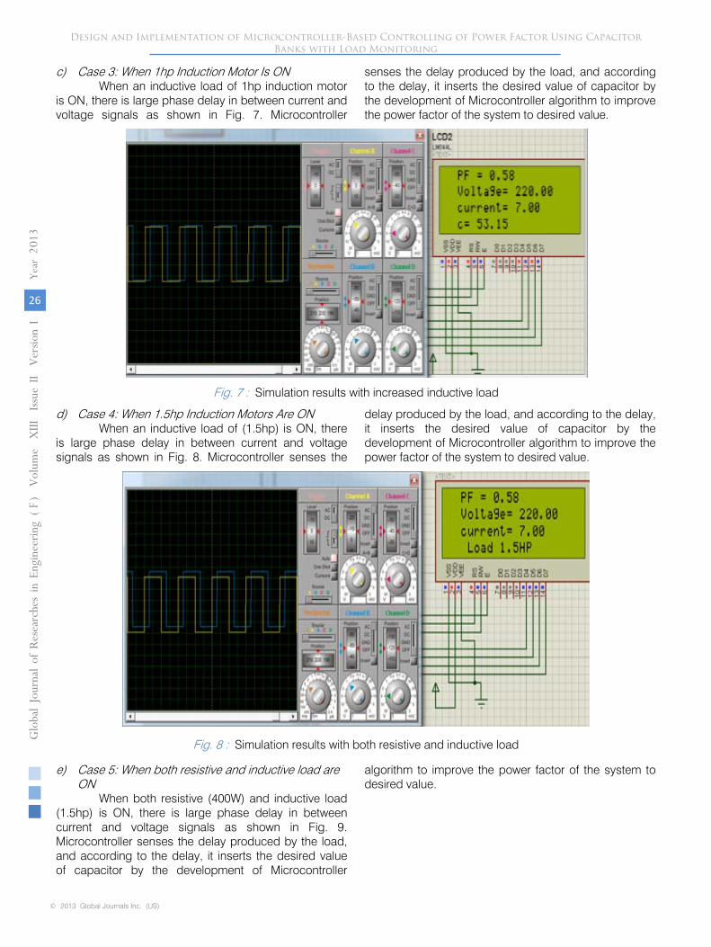
c) Case 3: When 1hp Induction Motor Is ON When an inductive load of 1hp induction motor
is ON, there is large phase delay in between current and voltage signals as shown in Fig. 7. Microcontroller
senses the delay produced by the load, and according to the delay, it inserts the desired value of capacitor by the development of Microcontroller algorithm to improve the power factor of the system to desired value.
Fig. 7 : Simulation results with increased inductive load
d) Case 4: When 1.5hp Induction Motors Are ON When an inductive load of (1.5hp) is ON, there
is large phase delay in between current and voltage signals as shown in Fig. 8. Microcontroller senses the
delay produced by the load, and according to the delay, it inserts the desired value of capacitor by the development of Microcontroller algorithm to improve the power factor of the system to desired value.
Fig. 8 : Simulation results with both resistive and inductive load
e) Case 5: When both resistive and inductive load are ON
When both resistive (400W) and inductive load (1.5hp) is ON, there is large phase delay in between current and voltage signals as shown in Fig. 9. Microcontroller senses the delay produced by the load, and according to the delay, it inserts the desired value of capacitor by the development of Microcontroller
algorithm to improve the power factor of the system to desired value.
Design and Implementation of Microcontroller-Based Controlling of Power Factor Using Capacitor Banks with Load Monitoring
Globa
l Jo
urna
l of
Resea
rche
s in E
nginee
ring
Volum
e X
III Issue
II V
ersion
I
26
()
Year
013
2F
© 2013 Global Journals Inc. (US)

Fig. 9 : Simulation results with both resistive and inductive load
V. Hardware Results and Discussion
Main prototype model of the hardware is shown in Fig. 10.
Fig. 10 : Hardware Prototype
Whole system may be divided into three stages. First stage is concern with the step down
arrangement of the incoming voltage and current signals into the PIC voltage level (e.g. 5V). Here we have used the step down arrangement of the transformer.
Second stage is concerned with zero crossing level detection by using an IC (LM358) for voltage and current, the incoming signals. Voltage signal can be acquired by using Opto-coupler (IC # 4N25) at the output of Potential Transformer for detection. Current signal can be acquired by using Current Transformer connected at main AC line.
In third stage block diagram represents the Automatic power factor control with continuously load monitoring of the system as shown in Fig. 10, the main part of the circuit is Microcontroller (18F452) with crystal of 11MHz.
After acquiring voltage and current signals, they are then passed through the zero cross detector block (ZCD V and ZCD I), that converts both voltage and current waveforms in square-wave that are further provided to microcontroller to detect the delay between both the signals at the same time instant. Two bridge rectifier circuits are utilized to convert both AC voltage and current signal into pulsating DC signal that is further provided to ADC pin of Microcontroller for its conversion into digital signal, so that the microcontroller performs its further necessary task. After this the checking of RMS value for voltage and current is performed, these values are used in the algorithm of Microcontroller to select the capacitor of desired value to counteract the effect of low power factor of the load and monitor continuously which load is operated on the basis of current consumed by the load. Results of corrected power factor, needed capacitor value to correct the low power factor to desired value are shown on the LCD.
Fig. 11 : Hardware model with resistive load
a) Case 1 : When resistive load (400W) is ON When resistive load is ON, as shown in Fig. 11,
there is no phase delay between current and voltage signals and they are in phase. In this case the power
Design and Implementation of Microcontroller-Based Controlling of Power Factor Using Capacitor Banks with Load Monitoring
Globa
l Jo
urna
l of R
esea
rche
s in E
nginee
ring
Volum
e X
III Issue
II V
ersion
I
27
()
Year
013
2F
© 2013 Global Journals Inc. (US)

factor would be 0.9 as referenced value, so there is no insertion of capacitors, as shown in Fig. 12 and 13.
Fig. 12
: Zero crossing detection for resistive load
In case of resistive load the V and I are in phase so there is no insertion of capacitors to improve power factor as shown in Fig 13.
Fig.
13
: V and I behavior for resistive load
The load monitoring of resistive load by microcontroller is shown on LCD in Fig 14.
Fig.
14
: Load monitoring for resistive load
b)
Case 2
: When 0.5hp induction motor is ON
When an inductive load of 0.5hp motor is ON, there is phase delay between voltage and current signals, as shown in Fig. 15. Microcontroller senses the delay produced by the load, and according to the delay, it inserts the desired value of capacitor to improve the power factor of the system as shown in Fig 18.
Fig. 15 : V and I behavior before correction with 0.5hp inductive load
The zero-crossing detection of V and I signals for 0.5hp induction motor is shown in Fig 16.
Fig. 16 : Zero crossing detection before correction with 0.5hp inductive load
The load monitoring of 0.5hp induction motor is shown in Fig 17.
Fig. 17 : Load monitoring for 0.5hp inductive load
According to the phase delay in signals, microcontroller takes the intelligent decision and adds the desired value of capacitor (35.842µF) as shown in Fig 18.
Fig. 18 : LCD showing value of ‘C’
Design and Implementation of Microcontroller-Based Controlling of Power Factor Using Capacitor Banks with Load Monitoring
Globa
l Jo
urna
l of
Resea
rche
s in E
nginee
ring
Volum
e X
III Issue
II V
ersion
I
28
()
Year
013
2F
© 2013 Global Journals Inc. (US)

When the desired value of the capacitors added the required reactive power to the system, the current and voltage waveforms are in phase, as shown in Fig 19.
Fig. 19 : V and I behavior after correction with 0.5hp inductive load
After the insertion of required value of capacitor, the V and I zero cross detector signals are also in phase in accordance with the set referenced value of power factor (0.9).
Fig. 20 : Zero crossing detection after correction with 0.5hp inductive load
c) Case 3 : When 1hp Induction Motor Is ON When an inductive load of 1hp motor is ON,
there is phase delay in between current and voltage signals, as shown in Fig.21: Microcontroller senses the delay produced by the load, and according to the delay, it inserts the desired value of capacitor to improve the power factor of the system.
Fig. 21 : V and I behavior before correction with 1hp inductive load
The zero-crossing detection of V and I signals for 1hp induction motor is shown in Fig 22.
Fig. 22 : Zero crossing detection before correction with 1hp inductive load
The load monitoring of 1hp inductive load is shown in Fig. 23.
Fig.. 23 : Load monitoring for 1hp inductive load
According to the phase delay in signals, microcontroller takes the intelligent decision and adds the desired value of capacitor (58.148µF) as shown in Fig 24.
Fig. 24 LCD showing value of ‘C’
When the desired value of the capacitors added the required reactive power to the system, the current and voltage waveforms are in phase in accordance with the set referenced value of power factor (0.9), as shown in Fig 25.
Fig. 25
: V and I behavior after correction with 1hp
inductive load
Design and Implementation of Microcontroller-Based Controlling of Power Factor Using Capacitor Banks with Load Monitoring
Globa
l Jo
urna
l of R
esea
rche
s in E
nginee
ring
Volum
e X
III Issue
II V
ersion
I
29
()
Year
013
2F
© 2013 Global Journals Inc. (US)
:
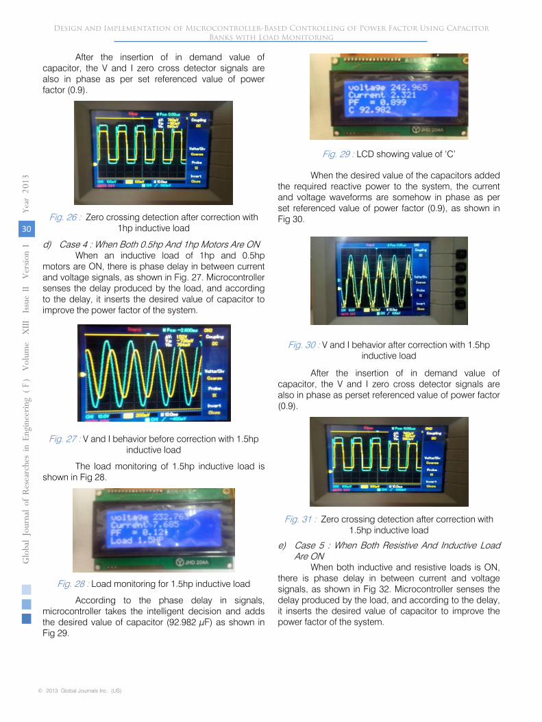
After the insertion of in demand value of capacitor, the V and I zero cross detector signals are also in phase as per set referenced value of power factor (0.9).
Fig. 26 : Zero crossing detection after correction with 1hp inductive load
d) Case 4 : When Both 0.5hp And 1hp Motors Are ON When an inductive load of 1hp and 0.5hp
motors are ON, there is phase delay in between current and voltage signals, as shown in Fig. 27. Microcontroller senses the delay produced by the load, and according to the delay, it inserts the desired value of capacitor to improve the power factor of the system.
Fig. 27
: V and I behavior before correction with 1.5hp
inductive load
The load monitoring of 1.5hp inductive load is
shown in Fig 28.
Fig. 28
: Load monitoring for 1.5hp inductive load
According to the phase delay in signals, microcontroller takes the intelligent decision and adds the desired value of capacitor (92.982 µF) as shown in Fig 29.
Fig. 29 : LCD showing value of ‘C’
When the desired value of the capacitors added the required
reactive power to the system, the current
and voltage waveforms are somehow in phase as per set referenced value of power factor (0.9), as shown in Fig 30.
Fig.
30
:
V and I behavior after correction with 1.5hp inductive load
After the insertion of in demand value of capacitor, the V and I zero cross detector signals are also in phase as perset referenced value of power factor (0.9).
Fig.
31
: Zero crossing detection after correction with 1.5hp inductive load
e)
Case 5 : When Both Resistive And Inductive Load Are ON
When both inductive and resistive loads is ON, there is phase delay in between current and voltage signals,
as shown in Fig 32. Microcontroller senses the delay produced by the load, and according to the delay, it inserts the desired value of capacitor to improve the power factor of the system.
Design and Implementation of Microcontroller-Based Controlling of Power Factor Using Capacitor Banks with Load Monitoring
Globa
l Jo
urna
l of
Resea
rche
s in E
nginee
ring
Volum
e X
III Issue
II V
ersion
I
30
()
Year
013
2F
© 2013 Global Journals Inc. (US)

Fig. 32 : V and I behavior before correction with resistive and inductive load
The load monitoring of resistive and inductive loads are shown in Fig. 33.
Fig. 33 : Load monitoring for resistive and inductive load
When the desired value of the capacitors added the required reactive power to the system, the current and voltage waveforms are somehow in phase as per set referenced value of power factor (0.9), as shown in Fig 34.
Fig. 34 : V and I behavior after correction with resistive and inductive load
According to the phase delay in signals, microcontroller takes the intelligent decision and adds the desired value of capacitor (92.982 µF) as shown in Fig. 35.
Fig. 35 : LCD showing value of ‘C’
VI. Conclusions
This project work is carried out to design and implement the automatic power factor controlling system using PIC Microcontroller (18F452). PIC Microcontroller senses the power factor by continuously monitoring the load of the system, and then according
to the lagging behavior of power factor due to load it performs the control action through a proper algorithm by switching capacitor bank through different relays and improves the power factor of the load. This project gives more reliable and user friendly power factor controlling system by continuously monitoring the load of the system. Measuring of power factor from load is achieved by using PIC Microcontroller developed algorithm to determine and trigger sufficient switching of capacitors in order to compensate demand of excessive reactive power locally, thus bringing power factor near to desired level.
References Références Referencias
1. Alexander, C.K. and Sadiku, M.N.O. (2000). “Fundamentals of Electric Circuit” United States of America: McGraw-Hill Companies,Inc.
2. Stephen, J. C. (1999). “Electric Machinery and Power System Fundamentals.” 3rdedition. United State of America: McGraw-Hill Companies, Inc.
3. John J. Grainger, William D. Stevenson (1994). “Power System Analysis” New York: McGraw-Hill.
4. Jos Arrillaga, Neville R. Watson (2003). “Power System Harmonics”2ndeditionChichester: John Wiley.
5. J. E. Miller (1982). “Reactive Power Control in Electric System” New York: Wiley
6. Roger C. Dugan, Mark F. McGranaghan, H. Wayne Beaty (1996),“Electrical Power Systems Quality” 1st.edition. New York: McGraw Hill.
7. B.C. Kok, C. Uttraphan, and H.H. Goh(2009). “A Conceptual Design of Microcontroller-Based Power Factor Corrector Circuit “pursued in practical applications.
8. Berthold Fuld'; Siegfried Kern; Ray Ridley (1991) “A Combined Buck and Boost Power-Factor-Controller for Three-Phase Input”, IEEE European Conference on Power Electronics and Applications, Volume: 7, Pages: 144-148.
9. Freitas, W.; Morelato, A.; WilsunXu; Sato, F. (2005) “Impacts of AC Generators and DSTATCOM Devices on the Dynamic Performance of Distribution Systems”, IEEE Transactions on Power Delivery, Volume: 20, Issue: 2, Pages: 1493-1501.
11. Jones, L. D.; Blackwell, D. (1983) “Energy Saver Power Factor Controller for Synchronous Motors”, IEEE Transactions on Power Apparatus and Systems, Volume: 5, Issue: 5, Pages: 1391-1394.
12. Kim, T.W.; Choi, J.H.; Kwon, B.H. (2004) “High-Performance Line Conditioner with Output Voltage Regulation and Power Factor Correction”, IEEE Proceedings on Electric Power Applications, Volume: 151, Issue: 1, Pages: 91- 97.
Design and Implementation of Microcontroller-Based Controlling of Power Factor Using Capacitor Banks with Load Monitoring
Globa
l Jo
urna
l of R
esea
rche
s in E
nginee
ring
Volum
e X
III Issue
II V
ersion
I
31
()
Year
013
2F
© 2013 Global Journals Inc. (US)
10. http://hyperphysics.phy-astr.gsu.edu/hbase/electric/acres.html

Global Journals Inc. (US)
Guidelines Handbook
2013
www.GlobalJournals.org