design and simulation of mems based piezoelectric...
TRANSCRIPT

141
Research Article
International Journal of Current Engineering and Technology ISSN 2277 - 4106
© 2014 INPRESSCO. All Rights Reserved.
Available at http://inpressco.com/category/ijcet
Design and Simulation of MEMS Based Piezoelectric Accelerometers
S.Sai KrishnaȦ*
, N.V.S.Ayyappa SaiȦ,S.Bhavya
Ḃ and K.Srinivasa Rao
Ȧ
ȦElectronics and Instrumentation Engineering, LBRCE, Mylavaram,Andhra Pradesh,India ḂElectronics and Communication Engineering, DMSSVHCE, Machilipatnam, Andhra Pradesh, India
Accepted 12 March 2014, Available online 01 April 2014, Special Issue-3, (April 2014)
Abstract
MEMS Accelerometer, the new inventions which revolutionized the technical world. Now, it’s time for the self assistive
accelerometers. In this paper, we have designed the trampoline, annular diaphragm structured piezoelectric
accelerometers using PZT-5H with COMSOL Multiphysics software tool for providing low transverse sensitivity along
one axis and good temperature stability. These accelerometers are incorporated into application specific integration
circuit (ASIC) and RF telemetry systems to facilitate wireless monitoring of industrial equipment.
Keywords: Accelerometer, Piezoelectric, Piezoelectric lead zirconate titanata (PZT)
1. Introduction
1 Accelerometers have been used in many fields, including
for activation of automotive safety systems (airbags,
electronic suspension), for machine and vibration
monitoring, and in biomedical applications for activity
monitoring. Micro machined accelerometers are widely
used by the automotive industry, because of their low cost,
small size, and broad frequency response. Three sensing
mechanisms, piezoresistive, capacitive, and piezoelectric
are most commonly utilized for MEMS accelerometers;
each one has limitations and advantages. Compared to
piezoresistive and capacitive accelerometers, there have
been fewer reports of micro machined piezoelectric
accelerometers. ZnO and PZT films are the two primary
materials reported for use in bulk or surface-micro
machined piezoelectric MEMS accelerometers.
Since the electromechanical coupling coefficients and the
piezoelectric constants of PZT are much higher than those
of ZnO films, the charge sensitivities of piezoelectric
MEMS accelerometers using ZnO films are relatively
small. Therefore, this work concentrated on the use of PZT
films. Several groups have previously reported on the use
of PZT MEMS accelerometers. In 1996, Nemirovsky et al.
designed a PZT thin-film piezoelectric accelerometer with
a calculated sensitivity of 320 mV/g, however, it has not
been fabricated. In 1997, Kim et al. fabricated a surface-
micro machined PZT accelerometer using cantilever
beams as the sensing structure. No dynamic frequency
response measurement was reported. In addition, surface
micromachining limits the thickness of microstructures; as
a result, the sensitivity is limited. In 1999, bulk-micro
machined accelerometers were fabricated and tested by
*Corresponding author: S.Sai Krishna
Eichner et al. A seismic mass and two silicon beams were
used as the sensing structure; an average sensitivity of 0.1
mV/g was measured and the resonant frequency was
calculated at 13 kHz. Beeby et al. fabricated a bulk micro
machined accelerometer using PZT thick films, which
were pre- pared by screen-printing processes. There are
two previous reports on the development of PZT-based
accelerometers fabricated using deep reactive ion etching:
one optimized for high sensitivities at low frequencies
(300 Hz); the other designed for broader bandwidth
operation.
2. About COMSOL Multiphysics
COMSOL Multiphysics 4.3b, Computer simulation has
become an essential part of science and engineering.
Digital analysis of components, in particular, is important
when developing new products or optimizing designs.
Today a broad spectrum of options for simulation is
available; researchers use everything from basic
programming languages to various high-level packages
implementing advanced methods. Though each of these
techniques has its own unique attributes, they all share a
common concern: Can you rely on the results? When
considering what makes software reliable, it’s helpful to
remember the goal: you want a model that accurately
depicts what happens in the real world. A computer
simulation environment is simply a translation of real-
world physical laws into their virtual form. How much
simplification takes place in the translation process helps
to determine the accuracy of the resulting model.
It would be ideal, then, to have a simulation
environment that included the possibility to add any
physical effect to your model. That is what COMSOL is
S.Sai Krishna et al International Journal of Current Engineering and Technology, Special Issue-3, (April 2014)
142
all about. It’s a flexible platform that allows even novice
users to model all relevant physical aspects of their
designs. Advanced users can go deeper and use their
knowledge to develop customized solutions, applicable to
their unique circumstances. With this kind of all-inclusive
modeling environment, COMSOL gives you the
confidence to build the model you want with real world
precision.
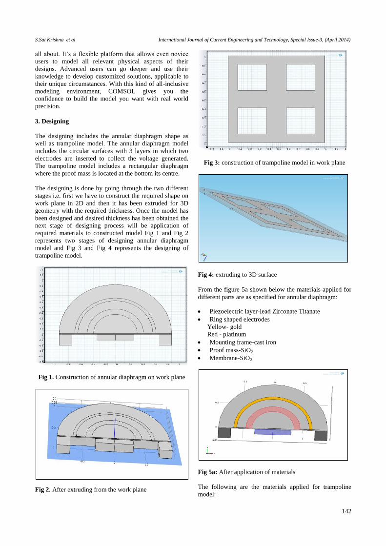
3. Designing
The designing includes the annular diaphragm shape as
well as trampoline model. The annular diaphragm model
includes the circular surfaces with 3 layers in which two
electrodes are inserted to collect the voltage generated.
The trampoline model includes a rectangular diaphragm
where the proof mass is located at the bottom its centre.
The designing is done by going through the two different
stages i.e. first we have to construct the required shape on
work plane in 2D and then it has been extruded for 3D
geometry with the required thickness. Once the model has
been designed and desired thickness has been obtained the
next stage of designing process will be application of
required materials to constructed model Fig 1 and Fig 2
represents two stages of designing annular diaphragm
model and Fig 3 and Fig 4 represents the designing of
trampoline model.
Fig 1. Construction of annular diaphragm on work plane
Fig 2. After extruding from the work plane
Fig 3: construction of trampoline model in work plane
Fig 4: extruding to 3D surface
From the figure 5a shown below the materials applied for
different parts are as specified for annular diaphragm:
Piezoelectric layer-lead Zirconate Titanate
Ring shaped electrodes
Yellow- gold
Red - platinum
Mounting frame-cast iron
Proof mass-SiO2
Membrane-SiO2
Fig 5a: After application of materials
The following are the materials applied for trampoline
model:
S.Sai Krishna et al International Journal of Current Engineering and Technology, Special Issue-3, (April 2014)
143
Blue -- Piezoelectric Lead Zirconate Titanate.
Gray -- SiO2
Fig 5b: materials applied for trampoline model
3.1 Meshing
Meshing is done for the device in order to have good study
of results, i.e. when the meshing is done the force or the
stress applied on the device will be equally distributed so
that the results will be exact. The meshing can of different
ways fine, extra fine wider etc. according to the device we
can select the type. Here the normal meshing have been
used. The following pictures show the mesh formed for
annular diaphragm as well as trampoline models .
Fig 6a. After the application of mesh
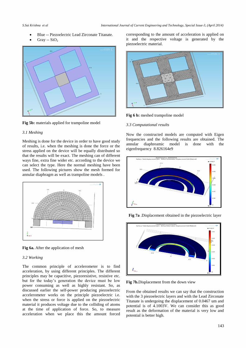
3.2 Working
The common principle of accelerometer is to find
acceleration, by using different principles. The different
principles may be capacitive, piezoresistive, resistive etc.
but for the today’s generation the device must be low
power consuming as well as highly resistant. So, as
discussed earlier the self-power producing piezoelectric
accelerometer works on the principle piezoelectric i.e.
when the stress or force is applied on the piezoelectric
material it produces voltage due to the colliding of atoms
at the time of application of force. So, to measure
acceleration when we place this the amount forced
corresponding to the amount of acceleration is applied on
it and the respective voltage is generated by the
piezoelectric material.
Fig 6 b: meshed trampoline model
3.3 Computational results
Now the constructed models are computed with Eigen
frequencies and the following results are obtained. The
annular diaphreamic model is done with the
eigenfrequency 8.826164e9
Fig 7a .Displacement obtained in the piezoelectric layer
Fig 7b.Displacement from the down view
From the obtained results we can say that the construction
with the 3 piezoelectric layers and with the Lead Zirconate
Titanate is undergoing the displacement of 0.0467 um and
potential is of 4.1003V. We can consider this as good
result as the deformation of the material is very low and
potential is better high.
S.Sai Krishna et al International Journal of Current Engineering and Technology, Special Issue-3, (April 2014)
144
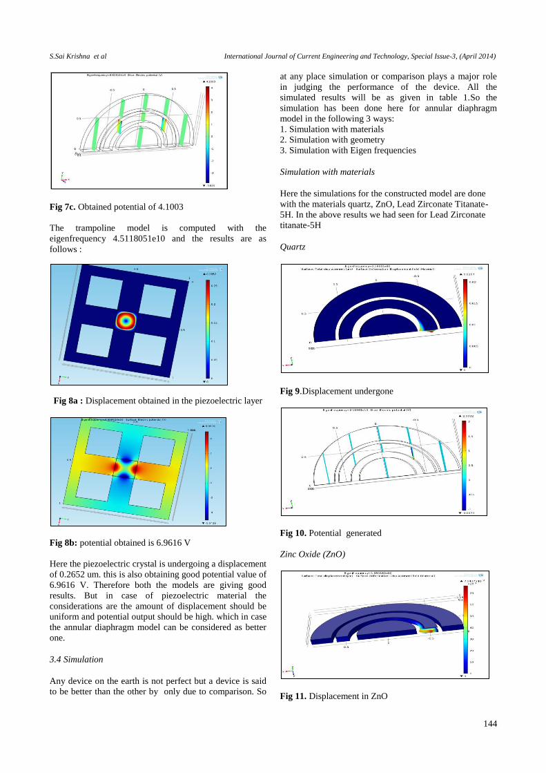
Fig 7c. Obtained potential of 4.1003
The trampoline model is computed with the
eigenfrequency 4.5118051e10 and the results are as
follows :
Fig 8a : Displacement obtained in the piezoelectric layer
Fig 8b: potential obtained is 6.9616 V
Here the piezoelectric crystal is undergoing a displacement
of 0.2652 um. this is also obtaining good potential value of
6.9616 V. Therefore both the models are giving good
results. But in case of piezoelectric material the
considerations are the amount of displacement should be
uniform and potential output should be high. which in case
the annular diaphragm model can be considered as better
one.
3.4 Simulation
Any device on the earth is not perfect but a device is said
to be better than the other by only due to comparison. So
at any place simulation or comparison plays a major role
in judging the performance of the device. All the
simulated results will be as given in table 1.So the
simulation has been done here for annular diaphragm
model in the following 3 ways:
1. Simulation with materials
2. Simulation with geometry
3. Simulation with Eigen frequencies
Simulation with materials
Here the simulations for the constructed model are done
with the materials quartz, ZnO, Lead Zirconate Titanate-
5H. In the above results we had seen for Lead Zirconate
titanate-5H
Quartz
Fig 9.Displacement undergone
Fig 10. Potential generated
Zinc Oxide (ZnO)
Fig 11. Displacement in ZnO
S.Sai Krishna et al International Journal of Current Engineering and Technology, Special Issue-3, (April 2014)
145
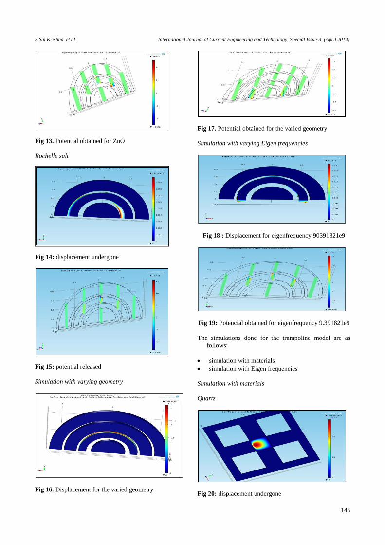
Fig 13. Potential obtained for ZnO
Rochelle salt
Fig 14: displacement undergone
Fig 15: potential released
Simulation with varying geometry
Fig 16. Displacement for the varied geometry
Fig 17. Potential obtained for the varied geometry
Simulation with varying Eigen frequencies
Fig 18 : Displacement for eigenfrequency 90391821e9
Fig 19: Potencial obtained for eigenfrequency 9.391821e9
The simulations done for the trampoline model are as
follows:
simulation with materials
simulation with Eigen frequencies
Simulation with materials
Quartz
Fig 20: displacement undergone

S.Sai Krishna et al International Journal of Current Engineering and Technology, Special Issue-3, (April 2014)
146
Fig 21: Potential obtained
ZnO(Zinc Oxide)
Fig 22: Displacement undergone
Fig 23: Potential obtained
Rochelle Salt
Fig 24: Displacement undergone
Fig 25: Potential obtained
Simulation with Eigen frequencies
Fig 26: Displacement undergone
Fig 25: Potential obtained
By the study of the Obtained Results we can say that the
annular diaphragm model is more sensitive when
compared to trampoline model as these are more sensible
to low frequencies. table.1 summarizes the amount of
potential with the corresponding displacement in each
case.
4. Conclusions
The MEMS accelerometers especially created a revolution
in the electronic devices, so to keep up the standards of
accelerometers and to cop up with the developing
technology, today the MEMS accelerometers should be
developed with various principles and different models for
better results. The piezoelectric MEMS accelerometers,

S.Sai Krishna et al International Journal of Current Engineering and Technology, Special Issue-3, (April 2014)
147
Table 1 Amount of potential with the corresponding displacement in each case.
Type of Simulation Material Geometry
4-Layer
Eigen
frequencies model out put PZT-5H Quartz Rochelle
Salt
ZnO
annular diaphragm displacement 0.0617um 0.0207um 0.00981um 0.7643um 0.2099um 0.206um
annular diaphragm potential(V) 4.1003 2.0332 15.472 5.0855 0.677 15.571
trampoline displacement 0.2652um
2.829*10-
9m
8.074*10-
9m
0.0123um not
applicable
0.0202um
trampoline potential(V) 6.9616 8.9933 7.6317 6.6338 not
applicable
10.924
combining a novel annular diaphragm , trampoline design
and high electromechanical coupling thick PZT films,
demonstrate high sensitivities and with broad usable
frequency ranges. In this paper our results shows, the
design accelerometer provides good sensitivity and good
temperature stability.
Acknowledgement
We would like to thank the Director and the Management
of LBRCE for providing us the necessary facilities to carry
out this work.
We also want to extend our sincere thanks to incharge
& coordinator of National MEMS design Centre for their
constant support.
References
L.-P. Wang, K. Deng, L. Zou, R. Wolf, R. J. Davis, and S.
Trolier- McKinstry, “Microelectromechanical Systems
(MEMS) accelerometers with a novel sensing structure using
piezoelectric Lead Zirconate Ti- tanate (PZT) thick films,”
IEEE Electron Device Lett., vol. 23, no. 4, pp. 182–184,
2002.
K. Kunz, P. Enoksson, and G. Stemme, “Highly sensitive triaxial
silicon accelerometer with integrated PZT thin film
detectors,” Sensors and Ac- tuators, vol. A92, pp. 156–160,
2001.
N. Yazdi, F. Ayazi, and K. Najafi, “Micro machined inertial
sensors,” Proc. IEEE, vol. 86, pp. 1640–1659, Aug. 1998.
C. Song, B. Ha, and S. Lee, “Micro machined inertial sensors,”
in Proc. 1999IEEE/RSJ, International Conference on
Intelligent Robots and Systems, vol. 2, pp. 1049–1056.
P. L. Chen, R. S. Muller, R. D. Jolly, G. L. Halac, R. D. White,
A.P.Andrews, T.C.Lim, and M. E. Motamedi, “Integrated
silicon microbeam PI- FETaccelerometer, ”IEEE Trans.
Electronic Devices,vol.ED- 29,pp. 27–33, 1982.
P. L. Chen and R. S. Muller, “Integrated silicon Pi-FET
accelerometer with proof mass,” Sens. Actuators, vol. 5, pp.
119–126, 1984.
P. Scheeper, J. O. Gullov, and L. M. Kofoed, “A piezoelectric
triaxial accelerometer,” J. Micromech. Microeng., vol. 6, pp.
131–133, 1996.
R. de Reus, J. O. Gullov, and P. R. Scheeper, “Fabrication and
character- ization of a piezoelectric accelerometer,” J.
Micromech. Microeng., vol. 9, pp. 123–126, 1999.
P. Muralt, A. Kholkin, M. Kohli, and T. Maeder, “Piezoelectric
actuation of PZT thin-film diaphragms at static and resonant
conditions,” Sens. Actuators, vol. A53, pp. 398–404, 1996.
S. Buhlmann, B. Dwir, J. Baborowski, and P. Muralt, “Size
effect inmesoscopic epitaxial ferroelectric structures: Incr
ease of the piezoelectric response with decreasing feature
size,” Appl. Phys. Lett., vol. 80, no. 17, pp. 3195–3197, 2002.