design aspects of flexible pavement and quality control ... · pdf file1 design aspects of...
TRANSCRIPT

1
DESIGN ASPECTS OF FLEXIBLE PAVEMENT
AND QUALITY CONTROL MANAGEMENT
A REPORT SUBMITTED TO JNTU UNIVERSITY IN
PARTIAL FULFILLMENT OF THE REQUIREMENTS FOR
BACHELOR OF ENGINEERING
IN
CIVIL ENGINEERING
SUBMITTED BY:
S. BHARAT KUMAR (08241A0110)
CH. SIDDARTHA (08241A0153)
T. SURYA VAMSHI (08241A0150)
M. TEJENDRA VARMA (08248A0153)
V. VAMSHI KRISHNA (08241A0154)
Under the Guidance of
Associate.Prof. V.Gajendra
DEPARTMENT OF CIVIL ENGINEERING
GOKARAJU RANGARAJU INSTITUTE OF ENGINEERING & TECHNOLOGY
NIZAMPET ROAD, HYDERABAD-500090 APRIL 2012
2
DEPARTMENT OF CIVIL ENGINEERING
GOKARAJU RANGARAJU INSTITUTE OF ENGINEERING & TECHNOLOGY
NIZAMPET ROAD, HYDERABAD-500090 APRIL 2012
CERTIFICATE
This is to certify that project entitled “DESIGN ASPECTS OF FLEXIBLE PAVEMENT
AND QUALITY CONTROL MANAGEMENT” that is being submitted by S.Bharat Kumar
(08241A0110), CH. Siddartha (08241A0143), T.Surya Vamshi (08241A0150), M.Tejendra
Varma (08241A0153), V.Vamshi Krishna (08241A0154) in partial fulfillment of the
requirement for the award of Degree of Bachelor of Technology in Civi Engineering,
GOKARAJU RANGARAJU INSTITUTE of Engineering and Technology (Affiliated to
Jawaharlal Nehru Technological University, Hyderabad) Is a record of bonafide work carried
out by them under my guidance and supervision. The results embodied in this thesis have not
been submitted to any other University or Institute for the award of any degree.
Mr. Dr.G.Venkata Ramana, Mr. V.Gajendra,
Head of Department, Associate Professor,
Civil Dept., Griet, Civil Dept.,Griet,
Hyderabad. Hyderabad.
J.N Murthy
Principal, GRIET

3

4
ACKNOWLEDGEMENT
Success is epitome of hard work, cogency for fulfilling the mission, indefatigable
perseverance and most of all encouraging guidance and steering.
We express our sincere thanks to, MR. Jandhyala Murthy Principal, GRIET for the support
and motivation provided to us.
It gives us an immense pleasure to express our gratitude to Prof. Dr.G.Venkata Ramana ,
Head of Department of Civil Engineering and Associate Prof. V.Gajendra, for their
esteemed guidance and able supervision during the course of the project. Their constant
encouragement and co-operation made this project a success.
We would like to express our sincere thanks to M/s Aarvee Associates Pvt. Ltd, for
providing us an opportunity to complete our Industrial oriented project successfully, which is
a part of course curriculum. This training would not have been successfully completed
without the guidance and support of Mr. P. Sudheer Kumar (Highway Engineer) and the
entire Aarvee Associates Team. We are deeply indebted to the project team members who
were always ready to help us during project time.
S. BHARAT KUMAR
CH. SIDDARTHA
M. TEJENDRA VARMA
T. SURYA VAMSHI
V. VAMSHI KRISHNA

5
ABSTRACT
Highway and pavement design plays an important role in the DPR projects
Regarding the pavement design, it forms an important part of detailed engineering study. The
satisfactory performance of the pavement will result in higher savings in terms of vehicle
operating costs and travel time, which has a bearing on the overall economic feasibility of the
project. This project discusses about the design methods that are traditionally being followed
and examines the relative merits of flexible pavement.
Currently, majority of the Indian roads are flexible pavements, the ones having bituminous
layer/s. earlier, there used to be scarcity of cement and India went for flexible pavements with
bituminous toppings. Now, flexible pavement are preferred over cement concrete roads as
they have a great advantage that these can be strengthened and improved in stages with the
growth of traffic. Another major advantage of these roads is that their surfaces can be milled
and recycled for rehabilitation. The flexible pavements are less expensive also with regard to
initial investment and maintenance.
Organization and duties of each individual is framed in this and the same is followed. This
stands as the standards for the Quality Control Team. Using this, existing practical conditions
are checked and reached to a conclusion about how the quality is maintained
Main focus is on the Quality Control Management in a construction activity. Thesis is to be
prepared on how the Quality control management exist and the way it is being functioned. It
can be done by drawing comparisons with the standard way and practical way.

6
Contents
Chapter – 1: Introduction 11-16
1.1 Project Background 12
1.2 Technical Features Of The Project 13
1.3 Project Roads/ Approved Contractors 14
1.4 Location Plan Of The Project 15
1.5 Contract Package –Ii 16
Chapter – 2: Pavement Design 17-21
2.1 Introduction 17
2.2 Flexible Pavement 17
2.3 Rigid Pavement 19
2.4 Functions Of Pavement Components 20
2.4.1 Soil Subgrade 20
2.4.2 Sub-Base And Base Course 20
2.4.3 Wearing Course 21
2.5 Design Factors 21
Chapter – 3: Design Standards 22-29
3.1 Introduction 22
3.2 Road Design 22
3.2.1 Terrain Classification 22
3.2.2 Design Speed 23
3.2.3 Basic Principles Of Geometric Design 24
3.3 Cross Sectional Elements 24

7
3.3.1 Road Land Width 24
3.3.2 Land Width 24
3.3.3 Width Of The Shoulder 25
3.3.4 Side Slopes 25
3.3.5 Width Of Median And Edge Strip 26
3.3.6 Reduction Of Cross Section 26
3.3.7 Camber 27
3.4 Horizontal Alignment 28
3.4.1 Horizontal Curve 28
3.4.2 Superelevation 28
3.4.3 Gradients 29
3.4.4 Access Design Speed 29
Chapter – 4: Design Of Pavements 30-37
4.1 Soil And Material Properties 30
4.2 Traffic Surveys 30
4.2.1 Introduction 30
4.2.2 Design Traffic 30
4.3 Design Period 32
4.4 Vehicle Damage Factor 32
4.5 Subgrade Strength 33
4.6 Design Lane MSA 33
4.7 Design Composition 34
4.8 AASHTO 34
4.9 Design Composition 36

8
4.10 Adopted Pavement Design 36
4.11 Design Of Service Roads 37
Chapter – 5: Laboratory Tests 38-54
5.1 Tests 38
1. Grain Size Analysis 39
2. Free Swell Index 41
3. Field Density Test By Sand Replacement 42
4. Modified Proctor Compaction Test 44
5. Bitumen Extraction Test 47
6. California Bearing Test 49
Chapter – 6: Road Construction Activity 51-71
6.1 Earthwork Excavation 51
6.2 Embankment Construction 54
6.3 Subgrade Construction 57
6.4 Granular Sub Base Construction 59
6.5. Wet Mix Macadam Construction 61
6.6 Application Of Prime Coat 64
6.7
6.8
6.9
Application Of Tack Coat
Dense Bituminous Macadam Construction
Bituminous Concrete Construction
66
67
71

9
Chapter – 7: Plant And Machinery 75-84 7.1 Excavators 75
7.2 Motor Grader 76
7.3 Bulldozer 77
7.4 Wheel Loader 78
7.5 Stone Crusher 79
7.6
7.7
7.8
7.9
7.10
WMM Plant
Hot Mix Plant
Dumpers
Batching Plant
Sensor Pavers
80
81
82
83
84
Chapter – 8: Quality Management 85-96
8.1 Introduction 85
8.2 Quality Policy, Quality System And Quality Strategy 85
8.3 Quality Policy 86
8.4 Quality System 86
8.5 Quality Strategy 87
8.6 Planning 88
8.7 Control 88
8.8 Verification 89
8.9 Quality Management In Construction And Reporting 89
8.9.1 Management Responsibilities 89
8.9.2 Contractual Link Between Key Players 90

10
8.9.3
8.9.4
8.9.5
8.9.6
8.9.7
8.9.8
8.9.9
8.10
8.10.1
8.11
8.11.1
Organization Set Up Of The Project
Functions Of QA / QC System
Quality Management Reports
Distribution Of The Quality Management Report
Management Reviews
Monthly Progress Report
Progress Control
Quality Control and assurance
Quality Control Of Road Works
Construction Quality Control
General
91
92
93
94
94
94
95
95
95
96
96
Chapter-9: Conclusions And References 99-100
Chapter -10: Appendix 101

11
1. INTRODUCTION
Hyderabad Growth Corridor Limited (HGCL), a Joint Venture of Hyderabad Metro
Development Authority (HMDA) and Infrastructure Corporation of Andhra Pradesh
(INCAP), has awarded “The Consulting Services for Construction Supervision of
Construction of Eight lane access Controlled Expressway as Outer Ring Road to Hyderabad
City in the State of Andhra Pradesh, India in the Stretches from Shamirpet to Pedda
Amberpet -From Km.61.700 to Km.95.000(Northern Arc)” to NIPPON KOEI – aarvee
associates (JV) in association with Nippon Koei India Pvt. Ltd, being taken up with the loan
assistance of Japan International Cooperation Agency Under JICA Phase -2 Programme and
Loan Agreement No ID-P:198 and the Agreement has been signed on 29th March’2010.
The monthly progress report is prepared and submitted with respect to the Terms of
Reference (TOR) to the agreement between Nippon Koei, Japan in joint venture with Aarvee
Associates, India in association with Nippon Koei India Pvt. Ltd. The report includes Project
background, salient features of Civil Works, scope of Consulting Services and monthly
progress of works in comparison with the approved Work Programme in accordance with
Clause 11 of the General Condition of Contract. The report also covers the mobilization of
the Consultant and the Contractors.

12
1.1 PROJECT BACKGROUND
Hyderabad Growth Corridor Limited has contemplated construction of Outer Ring Road all
around the City of Hyderabad. The entire construction has been planned in two Phases viz.
Phase I and Phase II of total length of 158.01 Km. Phase I of Outer Ring Road is of length
24.38 Km under implementation with domestic funding. Balance Length of 133.63 Km is
taken up as Phase II. The Phase II is further divided in to Phase IIA & Phase IIB.
Government of Andhra Pradesh has secured loan from JICA. JICA has agreed for funding of
a part of the northern arc from km. 23.7 to km. 95 (Phase IIB). The Phase IIB, Northern Arc
further divided into six contract packages, out of which three contract packages from km 23.7
to km 61.70 have already been awarded and the works are in progress.
The project section from km. 61.700 to km. 95.00 is supposed to establish linkage between
Hyderabad-Karimnagar-Ramagundam Road and Hyderabad-Vijayawada section on NH-9.
This section also intersects the Warangal-Hyderabad section of NH-202 and two other radial
roads proposed to intersect the Outer Ring Road. It connects Shamerpet, Keesara,
Padmasalguda, Ghatkesar, Taramatipet and Pedda Amberpet in the northern sector of the
Hyderabad Suburban area.
The project road is 8-lane access controlled expressway with two lane service road on either
side. A 25 m dedicated railway corridor is reserved between the expressway and right side
service road. Underpasses are provided at all cross roads and suitable interchanges have been
provided at major junctions. Original Contract provision contemplates one partial cloverleaf
and 2 rotary interchanges in this section which is being revised into double trumpet
interchange based on the Toll Consultants requirements. Pedestrian underpasses have been
provided to facilitate connectivity between the service roads. The project is supposed to be
tolled road. Closed toll system is proposed with a provision to collect toll on the exit/entry
ramps at the interchanges. The traffic plying on the service roads will not be tolled as per
current system. Accordingly toll system would be design. ITS is another important feature of
this road, which would bring the Hyderabad Outer Ring Road in the list of expressways of
international standard.
13
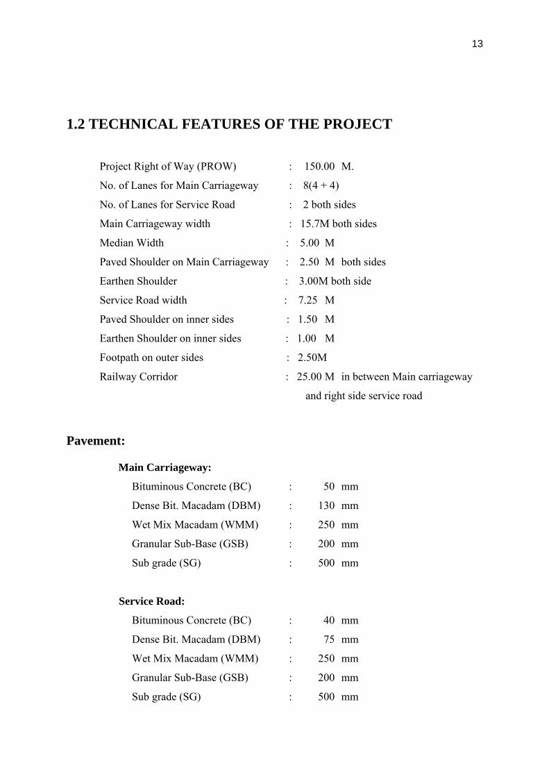
1.2 TECHNICAL FEATURES OF THE PROJECT
Project Right of Way (PROW) : 150.00 M.
No. of Lanes for Main Carriageway : 8(4 + 4)
No. of Lanes for Service Road : 2 both sides
Main Carriageway width : 15.7M both sides
Median Width : 5.00 M
Paved Shoulder on Main Carriageway : 2.50 M both sides
Earthen Shoulder : 3.00M both side
Service Road width : 7.25 M
Paved Shoulder on inner sides : 1.50 M
Earthen Shoulder on inner sides : 1.00 M
Footpath on outer sides : 2.50M
Railway Corridor : 25.00 M in between Main carriageway
and right side service road
Pavement:
Main Carriageway:
Bituminous Concrete (BC) : 50 mm
Dense Bit. Macadam (DBM) : 130 mm
Wet Mix Macadam (WMM) : 250 mm
Granular Sub-Base (GSB) : 200 mm
Sub grade (SG) : 500 mm
Service Road:
Bituminous Concrete (BC) : 40 mm
Dense Bit. Macadam (DBM) : 75 mm
Wet Mix Macadam (WMM) : 250 mm
Granular Sub-Base (GSB) : 200 mm
Sub grade (SG) : 500 mm
14
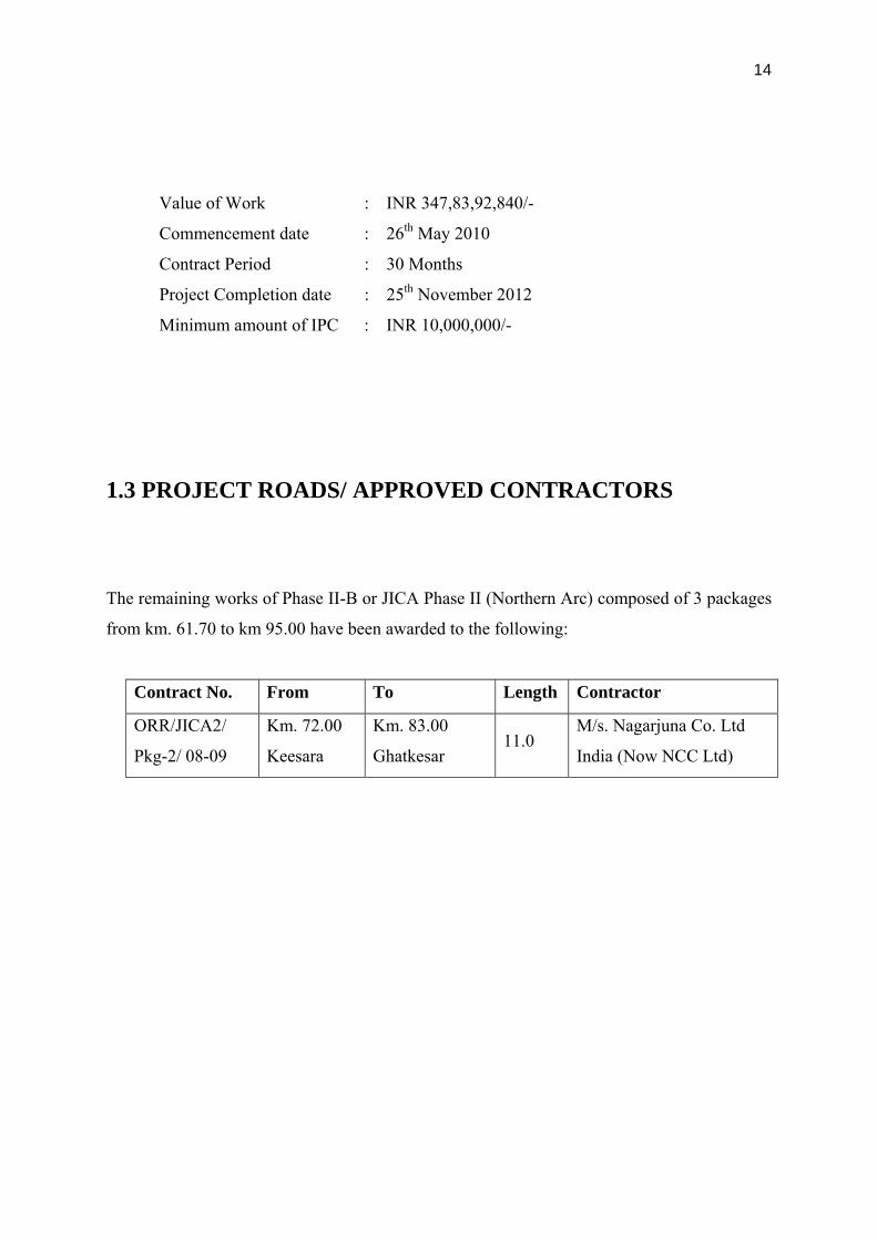
Value of Work : INR 347,83,92,840/-
Commencement date : 26th May 2010
Contract Period : 30 Months
Project Completion date : 25th November 2012
Minimum amount of IPC : INR 10,000,000/-
1.3 PROJECT ROADS/ APPROVED CONTRACTORS
The remaining works of Phase II-B or JICA Phase II (Northern Arc) composed of 3 packages
from km. 61.70 to km 95.00 have been awarded to the following:
Contract No. From To Length Contractor
ORR/JICA2/
Pkg-2/ 08-09
Km. 72.00
Keesara
Km. 83.00
Ghatkesar 11.0
M/s. Nagarjuna Co. Ltd
India (Now NCC Ltd)

15
1.4 LOCATION PLAN OF THE PROJECT
16
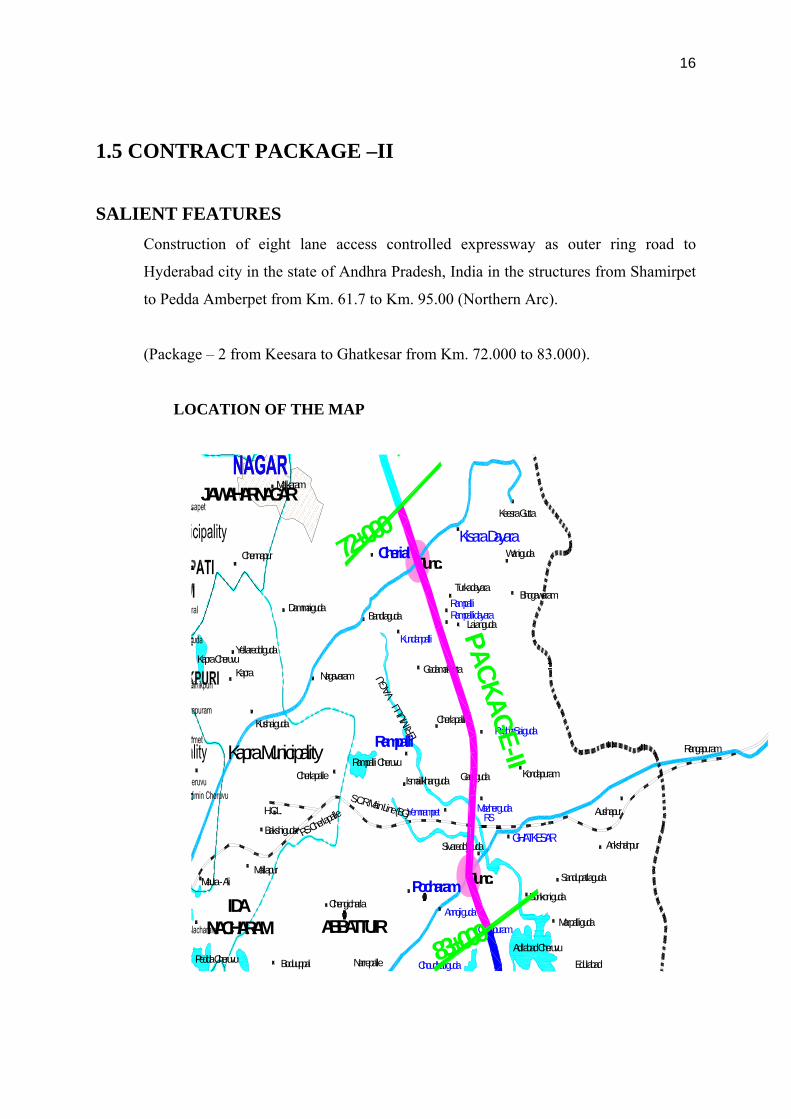
1.5 CONTRACT PACKAGE –II
SALIENT FEATURES Construction of eight lane access controlled expressway as outer ring road to
Hyderabad city in the state of Andhra Pradesh, India in the structures from Shamirpet
to Pedda Amberpet from Km. 61.7 to Km. 95.00 (Northern Arc).
(Package – 2 from Keesara to Ghatkesar from Km. 72.000 to 83.000).
LOCATION OF THE MAP
IDANACHARAM ABBATTUIR
Chennapur
Kapra CheruvuYellareddiguda
Kapra
Maula - Ali
Bakshiguda
Kapra MunicipalityKushaiguda
Dammaiguda
BoduuppalPedda Cheruvu
Mallapur
Chengicharla
Narrepalle
RS Cherlap
alle
Cherlapalle
Nagavaram
Kundanpalli
Godamakunta
Malkaram
Turkadayara
Kisara Dayara
EdulabadChoudhariguda
AnnojigudaGanapuram
Bonkoniguda
GHATKESAR
Sandupatlaguda
Marpalliguda
Ankshahpur
Adilabad Cheruvu
Aushapur
RampallidayaraLaianguda
Bhogawaram
Kondapuram
MazhergudaYemnampet
Cherlapalli
Keesra Gutta
Waniguda
RS
Rangapuram
H.C.L.
ERIM
ULLI
VAG
U
Pocharam
JAWAHARNAGAR
S.C.R.Main Line (BG)
Bandlaguda
PadmaSaiguda
Gantiguda
Junc.
Junc.
Sivareddyguda
Rampalli Cheruvu
Ismailkhanguda
Rampalli
Cherial
Rampalli
PACKAGE-II
72+000
83+000

17
2. PAVEMENT DESIGN
2.1 INTRODUCTION
Pavement is the durable surface material laid down on an area intended to sustain vehicular
or foot traffic, such as a road or walkway.
In the past cobblestones and granite sets were extensively used, but these surfaces have
mostly been replaced by asphalt or concrete
There are two types of pavements:
Flexible pavement
Rigid pavement
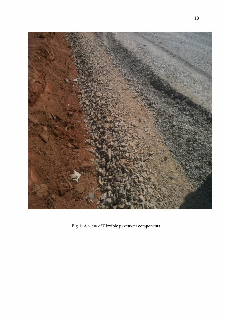
2.2 Flexible pavement:
Flexible pavements are those, which on the whole have low flexural strength and are rather
flexible in their structural action under the loads.
The flexible pavement layers reflect the deformation of the lower layers on to the surface of
the layer.
A typical Flexible pavement consists of four components:
surface course
base course
sub base course
soil sub grade
18
Fig 1: A view of Flexible pavement components

19
2.3 Rigid Pavement: Rigid pavements are those posses note worthy flexural strength. The stresses are not
transferred from grain to the lower layers as in case of flexible pavement layers. The rigid
pavements are made of Portland cement concrete-either plain, reinforced or prestressed
concrete. The plain cement concrete slabs are expected to take up to about 40 kg/cm2 flexural
stress. The rigid pavement has the slab action and is capable of transmitting the wheel load
stresses through a wide area below
Fig 2: A view of rigid pavement

20
Fig 3: The difference between flexible and rigid pavement
2.4 Functions of Pavement Components:
Soil Subgrade
Sub-base and Base Course
Wearing Course
2.4.1 Soil Subgrade: The soil subgrade is a layer of natural soil prepared to receive the layers of pavement
materials placed over it. The load on the pavement is ultimately received by the soil subgrade
for dispersion to the earth mass. It is essential that at no time, the soil subgrade is
overstressed. It means that the pressure transmitted on the top of the subgrade is within the
allowable limit, not to cause excessive stress condition or to deform the same beyond the
elastic limit. It is necessary to evaluate the strength properties of a soil subgrade. This helps
to designer to adopt the suitable values of the strength parameters for design purpose and in
case this supporting layer does not cum upto the expectations, the same is treated or stabilized
to suit the requirements.
2.4.2 Sub-base and Base Course: These layers are made of broken stones, bound or unbound aggregate. Some times in sub-
base course a layer of stabilized soil or selected granular soil is also used. In some places
boulders stones or bricks are also used as sun-base or soling course. When the subgrade
consists of the grained soils and when the pavement carries heavy wheel loads, there is a
tendency for these boulders stones or bricks to penetrate into the wet soil, resulting in the
formation of undulation and uneven pavement surface in flexible pavement.

21
Base course and Sub-base course are used under flexible pavement primarily to improve the
load supporting capacity by distributing the load through a finite thickness. Base course are
used in rigid pavement for:
Preventing pumping
Protecting the subgrade against frost action
2.4.3 Wearing course: The purpose of wearing course is to give a smooth riding surface that is dense. It resists
pressure exerted by tyres and takes up wear and tear due to the traffic. Wearing course also
offers a water tight layer against the surface water infiltration.
2.5 Design Factors
Factors to be considered in Design of Pavements
Pavement Design consists of two parts:
Mix design of materials to be used in each pavement components layer.
Thickness design of the pavement and the component layers.
The various factors to be considers for the design of pavements are given below:
i. Design wheel load
ii. Subgrade soil
iii. Climatic factors
iv. Pavement component materials
v. Environmental factors
vi. Special factors in the design of different types of pavement.
22
3. Design Standards
3.1 INTRODUCTION
Expressway, a controlled access facility is intended to provide most efficient speedy
movement of relatively high volumes of motorized traffic with higher degree of safety,
comfort and economy. Alignment characteristics and parameters of physical dimensions
should be such that the resulting road has inbuilt flexibility of adjustment for additional
carriageways in foreseeable future without any extravagant or wasteful expenditure, because
in a rapidly developing economy it may not always be possible to forecast the traffic growth
accurately.
Geometric and other elements should be preferably matched to the individual and collective
requirement of traffic using the facility. Predominant vehicles trucks and passenger vehicles
were considered in finalizing the basis for the design parameters like carriageway widths,
Capacities, Design Speeds and other geometric elements.
3.2 ROAD DESIGN
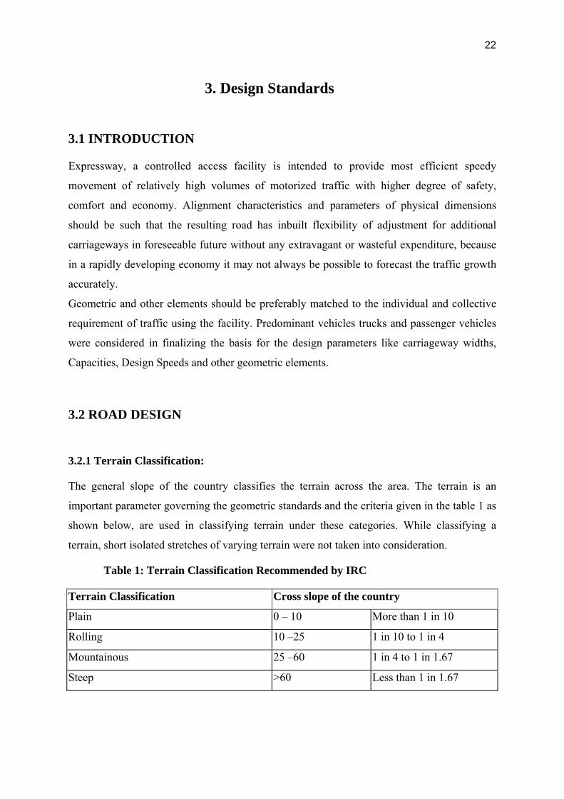
3.2.1 Terrain Classification:
The general slope of the country classifies the terrain across the area. The terrain is an
important parameter governing the geometric standards and the criteria given in the table 1 as
shown below, are used in classifying terrain under these categories. While classifying a
terrain, short isolated stretches of varying terrain were not taken into consideration.
Table 1: Terrain Classification Recommended by IRC
Terrain Classification Cross slope of the country
Plain 0 – 10 More than 1 in 10
Rolling 10 –25 1 in 10 to 1 in 4
Mountainous 25 –60 1 in 4 to 1 in 1.67
Steep >60 Less than 1 in 1.67

23
3.2.2 Design Speed:
Design speed is the basic criterion for determining all geometric features of horizontal and
vertical alignments. The design speeds for various terrain conditions are given in the table 2
as shown below. Design speed is mainly be used to determine the following parameters:
• Horizontal alignment radii
• Length of Vertical Curves / K factors
• Geometric layout of the interchanges (specifically layout of the accesses,
including length of taper and merging areas, and of weaving zones)
• Layout and characteristics of signs
Table 2: Design Speeds to be adopted for Different Terrain
Sl No Road
Classification
Design Speed (Km/h)
Plain Terrain Rolling Terrain Mountainous
Terrain
Ruling Minimum Ruling Minimum Ruling Minimum
1 Expressway 120 100 100 85 80 60
2 Link Road 100 80 80 65 50 40
In fact, in urban areas, even in plain terrain, there could be geometric constraints and controls
similar in their effects to mountainous terrain. Thus, design speed should be adapted in areas
with densely built environment having important facilities and other environmental
constraints.
Also, considering the above, in areas with close accesses to the project corridors exists, the
design speed should be adapted to suit the site conditions. This can be achieved by either
decreasing design speed on the main carriageway, or by providing an auxiliary lane
physically separated from main carriageway, with a different design speed from main
carriageway.
Design speed should also include provision for the approaches of adjacent road sections
(State Highways, National Highways, and Local Roads). This will require speed to be
reduced when approaching these sections. Normally, ruling design speed was taken as the
guiding criterion for the purpose of the geometric design. Minimum design speed was

24
however adopted where site condition and cost does not permit a design based on “Ruling
Design Speed”. In the link road section, the design speed was taken as 100 Kmph and for the
rest of the ORR the design speed is taken as 120 Kmph.
3.2.3 Basic Principles of Geometric Design:
The guidelines are intended for uniform practices to achieve optimum design standards for
Expressway. As a general rule, geometric features of a road do not allow for stage
construction. Improvement of features like grade, curvature and widening of cross drainage
structures at a later date can be very expensive and sometimes impossible.
Geometric design standards and specifications given in IRC: 73-1980 / AASHTO were
followed for the designing of Outer Ring Road. However, the minimum values have been
applied only where serious restrictions are implied from technical or economical
considerations. In General, the design standards adopted were more than the minimum values
suggested.
3.3 CROSS SECTIONAL ELEMENTS:
3.3.1 Road Land width:
Road land width also termed as right-of-way is the width of land acquired for road purposes.
The desirable land width for the Outer Ring Road is given in the following Table 3.
Table 3: Right of Way
Sl No Road classification Right of way (m)
1 Outer Ring Road (ORR) 150m
3.3.2 Lane width:
As per the specifications in the IRC: 73-1980, the recommended lane widths are 3.50m.
California State Highway standards allow for 3.6m wide lanes. As per the AASHTO design
standards, the recommended lane width for expressways is 3.75m. Since the Outer Ring Road
is going to be a high speed facility, it was felt necessary to keep the lane widths as per the
design standards given in AASHTO, and are given in the following table 4.
25
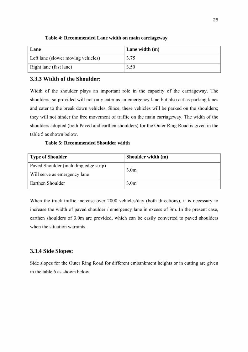
Table 4: Recommended Lane width on main carriageway
Lane Lane width (m)
Left lane (slower moving vehicles) 3.75
Right lane (fast lane) 3.50
3.3.3 Width of the Shoulder:
Width of the shoulder plays an important role in the capacity of the carriageway. The
shoulders, so provided will not only cater as an emergency lane but also act as parking lanes
and cater to the break down vehicles. Since, these vehicles will be parked on the shoulders;
they will not hinder the free movement of traffic on the main carriageway. The width of the
shoulders adopted (both Paved and earthen shoulders) for the Outer Ring Road is given in the
table 5 as shown below.
Table 5: Recommended Shoulder width
Type of Shoulder Shoulder width (m)
Paved Shoulder (including edge strip)
Will serve as emergency lane 3.0m
Earthen Shoulder 3.0m
When the truck traffic increase over 2000 vehicles/day (both directions), it is necessary to
increase the width of paved shoulder / emergency lane in excess of 3m. In the present case,
earthen shoulders of 3.0m are provided, which can be easily converted to paved shoulders
when the situation warrants.
3.3.4 Side Slopes:
Side slopes for the Outer Ring Road for different embankment heights or in cutting are given
in the table 6 as shown below.
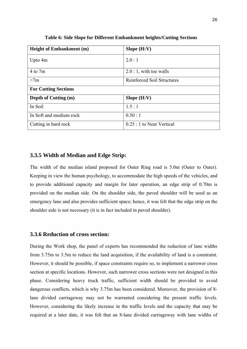
26
Table 6: Side Slope for Different Embankment heights/Cutting Sections
Height of Embankment (m) Slope (H:V)
Upto 4m 2.0 : 1
4 to 7m 2.0 : 1, with toe walls
>7m Reinforced Soil Structures
For Cutting Sections
Depth of Cutting (m) Slope (H:V)
In Soil 1.5 : 1
In Soft and medium rock 0.50 : 1
Cutting in hard rock 0.25 : 1 to Near Vertical
3.3.5 Width of Median and Edge Strip:
The width of the median island proposed for Outer Ring road is 5.0m (Outer to Outer).
Keeping in view the human psychology, to accommodate the high speeds of the vehicles, and
to provide additional capacity and margin for later operation, an edge strip of 0.70m is
provided on the median side. On the shoulder side, the paved shoulder will be used as an
emergency lane and also provides sufficient space; hence, it was felt that the edge strip on the
shoulder side is not necessary (it is in fact included in paved shoulder).
3.3.6 Reduction of cross section:
During the Work shop, the panel of experts has recommended the reduction of lane widths
from 3.75m to 3.5m to reduce the land acquisition, if the availability of land is a constraint.
However, it should be possible, if space constraints require so, to implement a narrower cross
section at specific locations. However, such narrower cross sections were not designed in this
phase. Considering heavy truck traffic, sufficient width should be provided to avoid
dangerous conflicts, which is why 3.75m has been considered. Moreover, the provision of 8-
lane divided carriageway may not be warranted considering the present traffic levels.
However, considering the likely increase in the traffic levels and the capacity that may be
required at a later date, it was felt that an 8-lane divided carriageway with lane widths of

27
3.5m (Inner two lanes) and 3.75m (outer two lanes) will be provided. Regarding the safety
aspect, the surplus of capacity provided at this stage might have a negative impact with
increase in vehicular speeds and road accidents.
3.3.7 Camber:
The camber on straight section of road should be recommended in the table 7 as shown
below:
Table 7: Camber for different surface types
Type Camber (%)
Carriageway (Flexible Pavement) 2.5%
Paved Shoulder 2.5%
Earthen Shoulder 3.5%
Carriageway (Rigid Pavement) 2.0%
At super-elevated road sections, the shoulder should normally have the slope of same
magnitude and direction as the pavement slopes subject to the minimum cross-fall allowable
for shoulder. The camber for earth shoulder should be at least 0.5% more than that for the
pavement subject to the minimum of 4%. However, 1.0% more slope than the camber for the
pavement is desirable; hence 3.5% camber is adopted for earthen shoulders.
28
3.4 HORIZONTAL ALIGNMENT
3.4.1 Horizontal Curve:
Horizontal curve consists of circular portion flanked by spiral transition at both ends. Design
speed, super elevation and coefficient of side friction affect the design of circular curves. The
provision of transition curves enhances the safety of the road users, as it will allow a smooth
change in the rate of change of superelevation, and also reduces the centrifugal forces on the
vehicle. Length of transition curve is determined on the basis of rate of change of centrifugal
acceleration or the rate of change of super elevation. The rate of change of super elevation is
considered to be 1:200, as prescribed in AASHTO, and the same rate has been adopted in this
project.
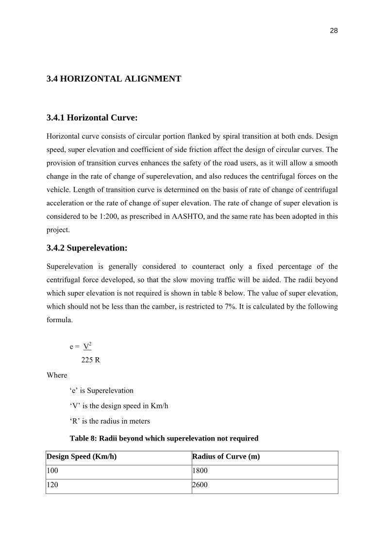
3.4.2 Superelevation:
Superelevation is generally considered to counteract only a fixed percentage of the
centrifugal force developed, so that the slow moving traffic will be aided. The radii beyond
which super elevation is not required is shown in table 8 below. The value of super elevation,
which should not be less than the camber, is restricted to 7%. It is calculated by the following
formula.
e = V2
225 R
Where
‘e’ is Superelevation
‘V’ is the design speed in Km/h
‘R’ is the radius in meters
Table 8: Radii beyond which superelevation not required
Design Speed (Km/h) Radius of Curve (m)
100 1800
120 2600

29
3.4.3 Gradients:
The gradients adopted in the design are as per guidelines given in the IRC manual. The
allowable difference in grade where no vertical curve is required is 0.4. The minimum length
of vertical summit curve is 140m and minimum length of valley curve is 60m. In general the
maximum gradient adopted in the design is 2%. Gradient values for roads in different terrains
are as shown in table 10.
Table 9: Gradients for Roads in Different Terrain
Sl. No Terrain Ruling
gradient
Limited
gradient
1 Plain or Rolling 2.0 %
(1 in 50)
2.5 %
(1 in 40)
2 Mountainous 2.5 %
(1 in 40)
3.0 %
(1 in 33.33)
3.4.4 Access design speed:
Care should be taken that signs and geometry match, and that sufficient information is given
to the user. This would be of great importance due to the presence of complex interchanges.
Conventional design speed values for accesses at entrance and exit are shown in table 11
below.
Table 10: Conventional design speed for accesses
Sl No Convention design speed (km/h)
Main
Carriageway
(120 km/h)
Collector /
Distributor (80
km/h)
1 Exit speed 70 55
2 Entrance speed 55 50

30
4. DESIGN OF PAVEMENTS
4.1 Soil and Material Properties:
From the soil and material investigations, the CBR values are found to be more than 10%.
From the quarry and borrow area investigations, the good quality material required for the
construction is available in abundance. The summary of test results are presented in Chapter
II – Material & Sub grade investigations of Main Volume.
4.2 Traffic Surveys:
4.2.1 Introduction:
An accurate estimate of the traffic that is likely to use the project road is very important as it
forms the basic input in planning, design, operation and financing. A thorough knowledge of
the travel characteristics of the traffic likely to use the project road as well as other major
roads in the influence area of the study corridor is, therefore, essential for future traffic
estimation. Hence, detailed traffic surveys were carried out to assess the present day traffic
and its characteristics.
4.2.2 Design Traffic:
Traffic for the estimation of the Msa was extracted from the Traffic Report. Present and
estimated traffic for future along the project road is presented in table 2 furnished below.

31
Table 1: Present and Projected traffic volume (PCUs) along the Project Corridor
Leg 2006 2011 2016 2021 2026 2031 2036
Leg-1 34,931 49,271 69,123 96,126 129,534 172,687 225,540
Leg-2 35,450 49,959 70,112 97,636 131,723 175,936 230,206
Leg-3 34,672 49,053 68,990 96,126 129,709 173,103 226,264
Leg-4 52,136 73,043 101,663 140,201 187,741 248,553 322,651
Leg-5 57,655 80,801 112,350 154,619 206,695 272,957 353,470
Leg-6 58,305 80,936 111,911 153,769 205,433 271,819 352,899
Leg-7 38,276 52,340 71,260 96,491 127,501 166,864 214,624
Leg-8 58,761 79,977 108,461 146,443 193,112 252,380 324,302
Leg-9 64,463 87,702 119,014 160,945 212,526 278,330 358,380
Leg-10 37,924 51,184 69,225 93,747 124,017 163,264 211,411
Leg-11 32,589 44,342 60,433 82,371 109,487 144,719 187,993
Leg-12 31,861 43,366 59,150 80,721 107,397 142,137 184,856
* Legs as detailed in Table 4.
IRC: 37-2001
Flexible pavement design has been carried out using the IRC: 37-2001 and AASHTO design
methods. IRC: 37-2001, a modification to IRC: 37-1984 has been revised to incorporate the
mechanistic design approach. In the new code pavement designs have been extended to cover
up to traffic loading of 150 Msa. Design was also carried out using the AASHTO pavement
design guidelines.
The scope of pavement design in this project can be divided into the following sections.
• Design of Flexible Pavement for the Main carriageway
• Design of Flexible Pavement for Service roads
In the design of flexible pavements, a subgrade CBR of 10% has been considered. Wherever
the CBR of existing soils was found to be less than 10%, select subgrade material, with a
thickness of 500mm, having a CBR of 10% or more has been considered in the design. If the
CBR of the existing sub grade is more than 10% it will be loosened and re-compacted and
then the new pavement layers will be laid on it. The availability of the soils with CBR more
than 10% has been thoroughly investigated and is found to be in sufficient quantity.

32
4.3 Design Period: A 20-year design period (2009 - 2029) is assumed for the design of flexible pavement.
4.4 Vehicle Damage Factor: Vehicle damage factor (VDF) is a multiplier to convert the number of
commercial vehicles of different axle loads and axle configuration to the number of standard
axle load repetitions. It is defined as equivalent number of standard axles per commercial
vehicle. The VDF varies with the vehicle axle configuration, axle loading, terrain, type of
road and from region to region. Axle load surveys were conducted on NH 7 and NH 9 at the
proposed junction with ORR. Vehicle damage factors are tabulated in table 3 as shown
below.
Table 2: Summary of Vehicle Damage Factors
Location 2-Axle
Truck
3-Axle
Truck
M-Axle
Truck LCV Buses
Shamshabad (NH-7) 3.21 2.41 2.57 0.23 0.50
Amberpet (NH-9) 2.66 3.17 4.92 0.36 0.30
Medchal (NH-7) 3.90 2.42 7.60 0.40 0.44
Pathancheruvu (NH-9) 1.50 2.60 2.65 0.14 -
Average 2.82 2.65 4.44 0.28 0.41
The above values are slightly lower than the values suggested in IRC: 37 – 2001 for trucks. In
any case, MSA has been calculated with both the VDFs for comparison and presented in table
4 as shown below.

33
Table 3: Design Lane MSA
S.No. Stretch
MSA as per
IRC: 37-
2001
MSA as per
observed
VDF
Suggested
Value
(MSA)
1 Shamshabad to APPA 101 65 100
2 APPA to Gandipet 99 64 100
3 Gandipet to Patancheru 101 65 100
4 Patancheru to Narsapur Rd 154 100 100
5 Narsapur Rd to Kandlakoya 179 116 100
6 Kandlakoya to Shameerpet 158 104 100
7 Shameerpet to Keesara rd 106 70 100
8 Keesara rd to Ghatkesar 160 106 100
9 Ghatkesar to Amberpet 172 115 100
10 Amberpet to Bongulur 86 58 100
11 Bongulur to Srinagar 75 51 100
12 Srinagar to Shamshabad 72 49 100
* 100 MSA has been considered in the design of pavement for phase II.
4.5 Sub grade Strength: The new pavement will be constructed on a sub grade with minimum soaked CBR
of 10%.
4.6 Design Lane MSA:
The base year traffic, traffic growth rates and the projected traffic for the design period for
each category of vehicles have been extracted from the Chapter 4 of main volume. The new
facility is expected to be opened for traffic in the year 2010 and for a design period of 20
34
years, the horizon year is 2029. Keeping in view the potential of the Outer Ring Road, and
the amount of traffic that could be diverted on the ORR, the pavement design was carried out
for a 100 Msa. The new pavement will be constructed on a sub grade with minimum soaked
CBR of 10%.
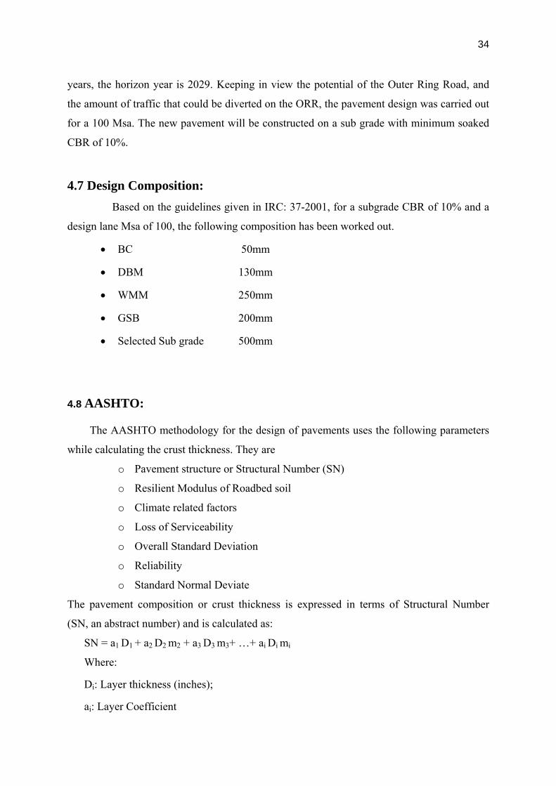
4.7 Design Composition: Based on the guidelines given in IRC: 37-2001, for a subgrade CBR of 10% and a
design lane Msa of 100, the following composition has been worked out.
• BC 50mm
• DBM 130mm
• WMM 250mm
• GSB 200mm
• Selected Sub grade 500mm
4.8 AASHTO:
The AASHTO methodology for the design of pavements uses the following parameters
while calculating the crust thickness. They are
o Pavement structure or Structural Number (SN)
o Resilient Modulus of Roadbed soil
o Climate related factors
o Loss of Serviceability
o Overall Standard Deviation
o Reliability
o Standard Normal Deviate
The pavement composition or crust thickness is expressed in terms of Structural Number
(SN, an abstract number) and is calculated as:
SN = a1 D1 + a2 D2 m2 + a3 D3 m3+ …+ ai Di mi
Where:
Di: Layer thickness (inches);
ai: Layer Coefficient

35
mi: Drainage Coefficient
The roadbed soil strength is expressed in terms of resilient modulus MR. The climate is
mainly related to the drainage as expressed in the factor m, and the pavement condition is
expressed in the pavement serviceability index PSI. Further, the traffic is expressed in “W18”,
being the cumulative number of equivalent standard axle loads of 18kip. Thus, AASHTO
uses the following equation:
Log10(W18)=ZR*So+9.36log10(SN+1)-0.20+((Log10(Δ�Psi/Po-
Pt))/(0.40+(1094/(SN+1)5.19))+ 2.32 * log10MR-8.07
Where:
W18: Cumulative Number of standard axles in design life
ΔPsi: Initial Serviceability (Po)-Terminal Serviceability (Pt)
So: Standard Deviation
ZR: Standard normal deviate for particular reliability(R)
SN: Structural number for the crust composition
The following values have been considered in the design
• Resilient modulus of the roadbed soil, MR computed from the empirical relation
between MR and CBR of the road bed soil
• Serviceability loss (ΔPsi) of 1.7 considering Po = 4.2 and Pt = 2.5
• Standard Normal Deviate Zr of -1.282 for a Reliability level of 90 %
• Overall standard deviation S0 is 0.49
Within the equation SN = a1 D1 + a2 D2 m2 + a3 D3 m3 the “m” value depends on the quality of
the drainage and the exposure time to moisture levels approaching saturation. A value of 1
has been considered for m2 and m3. (Table 2.4 of AASHTO).
The layer coefficients can be determined respectively from Figures 2.5, 2.6 and 2.7
(AASHTO, part II):
a1 for AC/DBM: 0.33
(For an elastic modulus of 1695 MPa at 35ºC derived from IRC: 37-2001)
a2 for WMM: 0.14 with CBR = 100
a3 for GSB: 0.11 with CBR > = 30

36
4.9 Design Composition: Based on the guidelines given in AASHTO Pavement Design Guide, 1993,
for a subgrade CBR of 10% and a design lane Msa of 100, the following composition has
been worked out.
• BC 50mm
• DBM 300mm
• WMM 175mm
• GSB 100mm
• Selected Subgrade 500mm
4.10 Adopted Pavement Design:
The pavement composition suggested by IRC: 37-2001 has been considered for the
project road. Since, the bituminous layer thickness is coming very high in the case of
AASHTO pavement design, and moreover, also keeping in view the susceptibility of the
bitumen to the rise in temperatures, the pavement composition suggested by IRC: 37-2001
has been adopted.
The adopted pavement composition for the main carriageway is given below:
• BC 50mm
• DBM 130mm
• WMM 250mm
• GSB 200mm
• Select Subgrade 500mm

37
4.11 DESIGN OF SERVICE ROADS:
Service roads will carry a lower MSA than the main carriageway. Local traffic viz., 2/3
wheelers, cars/ jeeps/ vans along with the commercial vehicles which would like to approach
the nearest interchange will use the service roads. Hence, the pavement is designed for 20
Msa, and for a sub grade CBR of 10%. The recommended pavement design is given below:
• BC 40mm
• DBM 75mm
• WMM 250mm
• GSB 200mm
• Select Subgrade 500mm

38
5. LABORATORY TESTS
5.1 Tests:
1. Grain Size Analysis (GSA)
2. Free Swell Index (FSI)
3. Field Density Test by Sand Replacement Method
4. Modified Proctor Compaction Test
5. Bitumen Extraction Test
6. California Bearing Ratio Test (CBR Test)
39
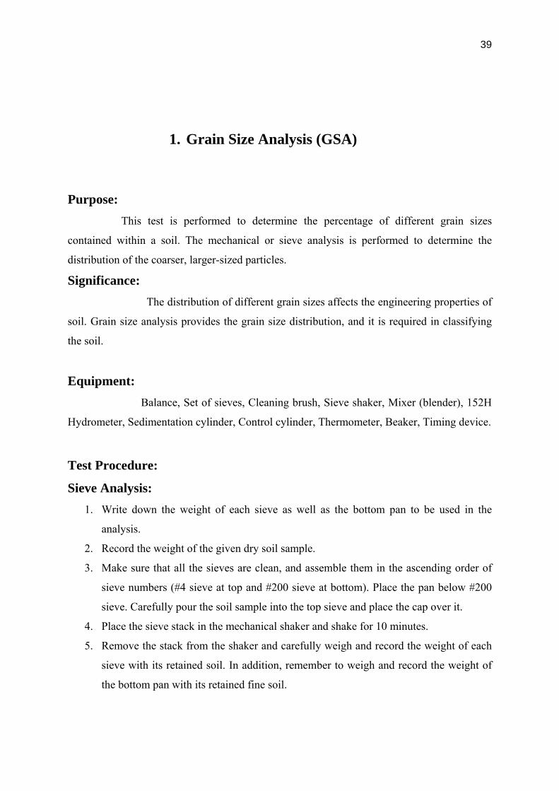
1. Grain Size Analysis (GSA)
Purpose: This test is performed to determine the percentage of different grain sizes
contained within a soil. The mechanical or sieve analysis is performed to determine the
distribution of the coarser, larger-sized particles.
Significance: The distribution of different grain sizes affects the engineering properties of
soil. Grain size analysis provides the grain size distribution, and it is required in classifying
the soil.
Equipment: Balance, Set of sieves, Cleaning brush, Sieve shaker, Mixer (blender), 152H
Hydrometer, Sedimentation cylinder, Control cylinder, Thermometer, Beaker, Timing device.
Test Procedure:
Sieve Analysis: 1. Write down the weight of each sieve as well as the bottom pan to be used in the
analysis.
2. Record the weight of the given dry soil sample.
3. Make sure that all the sieves are clean, and assemble them in the ascending order of
sieve numbers (#4 sieve at top and #200 sieve at bottom). Place the pan below #200
sieve. Carefully pour the soil sample into the top sieve and place the cap over it.
4. Place the sieve stack in the mechanical shaker and shake for 10 minutes.
5. Remove the stack from the shaker and carefully weigh and record the weight of each
sieve with its retained soil. In addition, remember to weigh and record the weight of
the bottom pan with its retained fine soil.

40

41
2. Free Swell Index (FSI)
Object: To determine the free swell index of soils.
Apparatus:
1) 425 micron IS sieve
2) Glass graduated cylinders – 2 nos 100ml capacity
3) Distilled water and kerosene.
Procedure:
1. Take two 10 grams soil specimens of oven dry soil passing through 425-micron IS sieve.
Each soil specimen shall be poured in each of the two glass graduated cylinders of 100ml
capacity.
2. One cylinder shall then be filled with kerosene oil and the other with distilled water up to
the 100ml mark.
3. After removal of entrapped air the soils in both the cylinders shall be allowed to settle.
Sufficient time (not less than 24 hours) shall be allowed for the soil sample to attain
equilibrium state of volume without any further change in the volume of the soils.
4. The final volume of soils in each of the cylinders shall be read out.

42
3. Field Density Test by Sand Replacement Method
OBJECTIVE: Determine the in situ density of natural or compacted soils using sand
pouring cylinders.
NEED AND SCOPE:
The in situ density of natural soil is needed for the determination of bearing capacity of soils,
for the purpose of stability analysis of slopes, for the determination of pressures on
underlying strata for the calculation of settlement and the design of underground structures.
It is very quality control test, where compaction is required, in the cases like embankment
and pavement construction.
APPARATUS REQUIRED:
1. Sand pouring cylinder of 3 litre/16.5 litre capacity, mounted above a pouring come and
separated by a shutter cover plate.
2. Tools for excavating holes; suitable tools such as scraper tool to make a level surface.
3. Cylindrical calibrating container with an internal diameter of 100 mm/200 mm and an
internal depth of 150 mm/250 mm fitted with a flange 50 mm/75 mm wide and about 5 mm
surrounding the open end.
4. Balance to weigh unto an accuracy of 1g.
5. Metal containers to collect excavated soil.
6. Metal tray with 300 mm/450 mm square and 40 mm/50 mm deep with a 100 mm/200 mm
diameter hole in the centre.
7. Glass plate about 450 mm/600 mm square and 10mm thick.
8. Clean, uniformly graded natural sand passing through 1.00 mm I.S.sieve and retained on
the 600micron I.S.sieve. It shall be free from organic matter and shall have been oven dried
and exposed to atmospheric humidity.
9. Suitable non-corrodible airtight containers.
10. Thermostatically controlled oven with interior on non-corroding material to maintain the
temperature between 1050C to 1100C.
11. A dessicator with any desiccating agent other than sulphuric acid.

43
PROCEDURE:
Calibration of the Cylinder
1. Fill the sand pouring cylinder with clean sand so that the level of the sand in the cylinder is
within about 10 mm from the top. Find out the initial weight of the cylinder plus sand (W1)
and this weight should be maintained constant throughout the test for which the calibration is
used.
2. Allow the sand of volume equal to that of the calibrating container to run out of the
cylinder by opening the shutter, close the shutter and place the cylinder on the glass sand
takes place in the cylinder close the shutter and remove the cylinder carefully. Weigh the
sand collected on the glass plate. Its weight(W2) gives the weight of sand filling the cone
portion of the sand pouring cylinder. Repeat this step at least three times and take the mean
weight (W2) Put the sand back into the sand pouring cylinder to have the same initial constant
weight (W1) Determination of Bulk Density of Soil
3. Determine the volume (V) of the container be filling it with water to the brim. Check this
volume by calculating from the measured internal dimensions of the container.
4. Place the sand poring cylinder centrally on yhe of the calibrating container making sure
that constant weight (W1) is maintained. Open the shutter and permit the sand to run into the
container. When no further movement of sand is seen close the shutter, remove the pouring
cylinder and find its weight (W3). Determination of Dry Density of Soil In Place
5. Approximately 60 sqcm of area of soil to be tested should be trimmed down to a level
surface,approximately of the size of the container. Keep the metal tray on the level surface
and excavate a circular hole of volume equal to that of the calibrating container. Collect all
the excavated soil in the tray and find out the weight of the excavated soil (Ww). Remove the
tray, and place the sand pouring cylinder filled to constant weight so that the base of the
cylinder covers the hole concentrically. Open the shutter and permit the sand to run into the
hole. Close the shutter when no further movement of the sand is seen. Remove the cylinder
and determine its weight (W3).
6. Keep a representative sample of the excavated sample of the soil for water content
determination.

44
4. Modified Proctor Compaction Test
Equipment: 1. Proctor mould with a detachable collar assembly and base plate.
2. Manual rammer weighing 2.5 kg and equipped to provide a height of drop to a free fall of
30 cm.
3. Sample Extruder.
4. A sensitive balance.
5. Straight edge.
6. Squeeze bottle
7. Mixing tools such as mixing pan, spoon, trowel, spatula etc.
8. Moisture cans.
9. Drying Oven.
Test procedure:
1. Obtain approximately 10 lb (4.5 kg) of air-dried soil in the mixing pan, break all the lumps
so that it passes No. 4 sieve.
2. Add approximate amount of water to increase the moisture content by about 5%.
3. Determine the weight of empty proctor mould without the base plate and the collar.
W1, (lb).
4. Fix the collar and base plate
5. Place the first portion of the soil in the Proctor mould as explained in the class and
compact the layer applying 25 blows.
6. Scratch the layer with a spatula forming a grid to ensure uniformity in distribution of
compaction energy to the subsequent layer. Place the second layer, apply 25 blows, place the
last portion and apply 25 blows.
7. The final layer should ensure that the compacted soil is just above the rim of the
compaction mould when the collar is still attached.

45
8. Detach the collar carefully without disturbing the compacted soil inside the mould and
using a straight edge trim the excess soil leveling to the mould.
9. Determine the weight of the mould with the moist soil W2, (lb). Extrude the sample and
break it to collect the sample for water content determination preferably from the middle of
the specimen.
10. Weigh an empty moisture can, W3, (g) and weigh again with the moist soil obtained from
the extruded sample in step9, W4, (g). Keep this can in the oven for water content
determination.
11. Break the rest of the compacted soil with hand (visually ensure that it passes US Sieve
No.4). Add more water to increase the moisture content by 2%.
12. Repeat steps 4 to 11. During this process the weight W2 increases for some time with the
increase in moisture and drops suddenly. Take two moisture increments after the weights
starts reducing. Obtain at least 4 points to plot the dry unit weight, moisture content variation.
13. After 24 hrs recover the sample in the oven and determine the weight W5, (g).
14. Fill out the following table completely; Calculate rows 9 and 10, these two will give one
point of the plot.

46

47
5. Bitumen Extraction Test
Aim of the test: The method described is a procedure used to determine the bitumen content of
bitumen aggregate mixtures.
Units of Measure: The bitumen content is expressed as a percent by dry weight of extracted aggregate.
Apparatus And Materials:
Equipment: Centrifuge extractor with a bowl. The extractor must be capable of rotating the bowl at
controlled variable speeds up to 3600 rpm.
Paper or felt filter rings to be placed on the rim of the bowl and beneath the bowl lid.
Scale capable of weighing to 2500 g at a 0.1 g accuracy.
Heating equipment such as electric stove.
500 ml cup or beaker.
Hand Tools - spatula, small brush, scoop, large pan for collection of a representative
bitumen mix sample, pan for test sample.
Container for collection of bitumen laden solvent thrown from the bowl during extraction.
Materials: Solvents - suggested materials are benzene or Carbon Tetra chloride.

48
Procedure:
A representative sample about 400gm is exactly weighed and placed in the bowl of the
extraction appartatus and covered with commercial grade of benzene. Sufficient time (not
more than 1 hour) is allowed for the solvent to disintegrate the sample before running the
centrifuge.
The filter ring of the extractor is dried, weighed and then fitted around the edge of the bowl.
The cover of the bowl is clampled tightly. A beaker is placed under to collect the extract.
The machine is revolved slowly and then gradually, the speed is increased to a maximum of
3600 r.p.m. The speed is maintained til the solvent ceases to flow from the drain. The
machine is allowed to stop and 200 ml. of the benzene is added and the above procedure is
repeated.
A number of 200 ml. solvent additions (not less than three) are used till the extract is clear
and not darker than a light straw colour.
The filter ring from the bowl is removed, dried in air and then in oven to constant weight at
115o C and weighed. The fine materials that might have passed through the filter paper are
collected back from the extract preferably by centrifuging. The material is washed and dried
to constant weight as before.

49
6. California Bearing Ratio Test (CBR Test)
AIM: TO FIND THE BEARING CAPACITY OF A MATERIAL WITH THAT OF A
WELL-GRADED CRUSHED STONE.
APPARATUS:
Mould
Steel Cutting collar
Spacer Disc
Surcharge weight
Dial gauges
IS Sieves
Penetration Plunger
Loading Machine
Miscellaneous Apparatus
PROCEDURE:
Normally 3 specimens each of about 7 kg must be compacted so that their compacted
densities range from 95% to 100% generally with 10, 30 and 65 blows.
Weigh of empty mould

50
Add water to the first specimen (compact it in five layer by giving 10 blows per layer)
After compaction, remove the collar and level the surface.
Take sample for determination of moisture content.
Weight of mould + compacted specimen.
Place the mold in the soaking tank for four days (ignore this step in case of
unsoaked CBR.
Take other samples and apply different blows and repeat the whole process.
After four days, measure the swell reading and find %age swell.
Remove the mould from the tank and allow water to drain.
Then place the specimen under the penetration piston and place surcharge load of
10lb.
Apply the load and note the penetration load values.
Draw the graphs between the penetration (in) and penetration load (in) and find the
value of CBR.
Draw the graph between the %age CBR and Dry Density, and find CBR at required
degree of compaction.

51
6. ROAD CONSTRUCTION ACTIVITY
6.1 EARTHWORK EXCAVATION
General:
This item of work deals with earthworks in excavation in all types of soils is it for stacking of
suitable soils or disposal of unsuitable soils inclusive of necessary lead for transporting
materials as per the terms in contract documents.
Procedure:
1. These excavation works referred to herein shall be either pointing to the trench cutting
at the existing ground level in order to engage in sand blanketing (in case of meeting
with unsuitable soil) or this could be the case of excavations necessary to trim down
the excessive earth masses in order to prepare the base for pavement layers. Or else
this may be the case of excavation necessary for construction of side drains &
waterways.
2. All the excavations shall be carried out in conformity with the directions laid down
herein under and in a manner as approved by the Engineer. The work shall be so done
that the suitable materials available from excavation works are satisfactorily utilized as
decided upon beforehand.
3. Dealing generally herein with the trench excavation for sand blanketing and applying
generally the same mode of procedure in other forms of excavation, we append
hereunder the broad steps of construction in this regard.
4. On completion of site clearance, necessary ground survey shall be done in order to
mark the lines of toe excavation.

52
5. This shall be followed further by laboratory tests with regards to the samples of soil
materials collected randomly (under the proximity of Engineer’s representative) from
the respective stretches. Existing ground levels contours shall be jointly recorded in the
form of cross sections at 10 m intervals with the origin of base line being the proposed
center line of the road sector.
6. While the joint survey recording is being plotted the laboratory tests shall be carried
out and the results obtained thus submitted to the Engineer for further instructions. On
instructions by the Engineer, necessary excavation works shall be commenced. Prior to
such commencement, however, necessary lines shall be marked and jointly recorded
for extension of excavation works.
7. Excavation shall be done with the help of excavators EX-200, EX-100 or other suitable
plants depending upon the stretches & quantum of work.
8. Excavated earth shall either be required to be disposed off or stacked at site. This shall
be done as per the directions of the Engineer. In case of disposal of materials to other
place, required number of tippers compatible with the capacity of excavator & the
haulage shall be engaged to do the job.
9. Excavation shall be done up to the depths as detailed in the drawings or as directed by
the Engineer. However the works in normal course shall conform to the lines, grades &
slopes as specified.
10. While planning or executing excavations we will take adequate precautions against
causing of any water stagnation or soil erosion or water pollution.
11. Under special circumstances, not in the case of excavation for sand blanketing, where
we require blasting of rocks for excavation works, this shall be done only with the
written permission of the Engineer after complying with the necessary state
formalities.

53
12. In the case of intercepting with water table, water pumps shall be deployed
immediately to pump out the excessive water for working conditions. However no
delay shall be caused in this regard for obtaining further instructions from safety of
works and plant considerations.
13. As a necessary quality procedure, in order to record the instructions and works and
keep a regular documentation of inspections, checking, approvals or disapprovals with
necessary observations at all stages of the work from commencement till completion of
the excavation works, RFI shall be initiated by us with full endorsement of Engineer or
his representative obtained before closing the document.

54
6.2 EMBANKMENT CONSTRUCTION
This item of work deals with construction of road embankment with approved materials as
per the terms of contract agreement.
General:
This item of work shall be dealt with in complete compliance to the technical specifications;
placement and compaction shall be carried out in accordance with clause 305 of
specifications.
Drawings used for construction in respect of the alignment, level, cross sections in respective
stretches and other survey detail and relevant technical specifications viz. clause 305 of
technical specification in terms of mandatory guidelines for ensuring the quality of work.
Prior to the commencement of this work, the materials proposed to be used for such
embankment shall be sourced suitably. Different sources shall be earmarked for different
stretches giving due regard to the load of haulage and most importantly the suitability and
quantum of material availability.
The material used in embankment shall generally be soil, morrum, gravel, a mixture of these
or any other approved material. In respect of quality of material, such material shall be
ensured to be free of logs, stumps, roots, rubbish for any ingredients likely deteriorate or
affect the stability of the embankment. The material resulting from the roadway excavation if
found suitable will also be used.
55
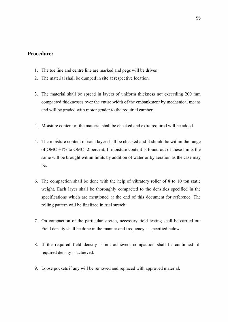
Procedure:
1. The toe line and centre line are marked and pegs will be driven.
2. The material shall be dumped in site at respective location.
3. The material shall be spread in layers of uniform thickness not exceeding 200 mm
compacted thicknesses over the entire width of the embankment by mechanical means
and will be graded with motor grader to the required camber.
4. Moisture content of the material shall be checked and extra required will be added.
5. The moisture content of each layer shall be checked and it should be within the range
of OMC +1% to OMC -2 percent. If moisture content is found out of these limits the
same will be brought within limits by addition of water or by aeration as the case may
be.
6. The compaction shall be done with the help of vibratory roller of 8 to 10 ton static
weight. Each layer shall be thoroughly compacted to the densities specified in the
specifications which are mentioned at the end of this document for reference. The
rolling pattern will be finalized in trial stretch.
7. On compaction of the particular stretch, necessary field testing shall be carried out
Field density shall be done in the manner and frequency as specified below.
8. If the required field density is not achieved, compaction shall be continued till
required density is achieved.
9. Loose pockets if any will be removed and replaced with approved material.

56
10. The above stages shall be repeated till the top level of the embankment is reached to
the specified levels and grades. The top levels shall be checked and shall be within
+20mm and -25mm of designed level.
11. All relevant QA and QC documents will be maintained for all stages of Embankment
Construction.
12. Where the ground supporting embankment is found to be unsuitable (material
mentioned in clause 305.2.1.1) or the original ground material is having free swell
index greater than 50% the same will be removed up to 500mm and will be replaced
with approved material as per clause 305.3.4.
Equipment/Machinery:
Motor Grader : 1 No. as a minimum
Tippers : 10 -20 No. as a minimum
Water Sprinkler : 1 No. as a minimum
Vibratory Roller : 80 to 100KN 1 No. as a minimum

57
6.3 SUBGRADE CONSTRUCTION
This item of work deals with construction of Subgrade (minimum 10% CBR) with approved
materials as per the terms of contract agreement.
General:
This item of work shall be dealt with in complete compliance to the technical specifications;
placement and compaction shall be carried out in accordance with clause 305 of
specifications.
The construction shall confirm to the specific alignment, lines and grades given in the
drawing.
Prior to the commencement of this work, the materials proposed to be used for such subgrade
shall be sourced suitably. Different sources shall be earmarked for different stretches giving
due regard to the load of haulage and most importantly the suitability and quantum of
material availability.
The material used in subgrade shall generally be soil, morrum, gravel, a mixture of these or
any other approved material. In respect of quality of material, such material shall be ensured
to be free of logs, stumps, roots, rubbish for any ingredients likely deteriorate or affect the
stability of the subgrade. The material resulting from the roadway excavation if found
suitable will also be used. Material which is having CBR value mentioned in technical
specification shall be used in subgrade.
Procedure:
1. The toe line and centre line are marked and pegs will be driven.
2. The material shall be dumped in site at respective location.
3. The material shall be spread in layers of uniform thickness not exceeding 200 mm
compacted thicknesses over the entire width of the subgrade by mechanical means and will
be graded with grader to the required camber.
4. Moisture content of the material shall be checked and extra required will be added.

58
5. The moisture content of each layer shall be checked and it should be within the range of
OMC +1% to OMC -2 percent. If moisture content is found out of these limits the same will
be brought within limits by addition of water or by aeration as the case may be.
6. The compaction shall be done with the help of vibratory roller of 8 to 10 ton static
weight. Each layer shall be thoroughly compacted to the densities specified in the
specifications which are mentioned at the end of this document for reference. The rolling
pattern will be finalized in trial stretch.
7. On compaction of the particular stretch necessary field testing shall be carried out Field
density shall be done in the manner and frequency as specified below.
8. If the required field density is not achieved, compaction shall be continued till required
density is achieved.
9. Loose pockets if any will be removed and replaced with approved material.
10. The above stages shall be repeated till the top level of the subgrade is reached to the
specified levels and grades. The top levels shall be checked and shall be within +20mm to -
25mm of designed level.
11. All relevant QA and QC documents will be maintained for all stages of subgrade
Construction.
12. In case the original ground is in subgrade level or is in cutting and if the density after
compaction is not 97% minimum the ground will be loosened up to a depth of 500mm and
will be compacted as per MoRT&H 305.3.
Equipment/Machinery: Motor Grader : 1 No. as a minimum
Tippers : 10 – 20 No. as a minimum
Water Sprinkler : 1 No. as a minimum
Vibratory Roller : 80 to 100KN 1 No. as a minimum

59
6.4 GRANULAR SUB BASE CONSTRUCTION
This item of work deals with construction of Granular sub base with approved materials as
per the terms of contract agreement.
General:
This item of work shall be dealt in compliance to the clause 401 of specifications.
The construction shall confirm to the specific alignment, lines and grades given in the
drawing.
Prior to the commencement of this work, the materials proposed to be used for such work
shall be sourced suitably. Different sources shall be earmarked for different stretches giving
due regard to the load of haulage and most importantly the suitability and quantum of
material availability.
The material used in Granular sub base shall be as per technical specification.
Procedure:
1.The toe line and centre line are marked and pegs will be driven.
2.The material shall be dumped in site at respective location.
3.The material shall be spread in layers of uniform thickness not exceeding 200 mm
compacted thicknesses over the entire width of the subgrade by mechanical means and
will be graded with grader to the required camber.
4.Moisture content of the material shall be checked and extra required will be added.
5.The moisture content of each layer shall be checked and it should be within the range of
OMC +1% to OMC -2 percent. If moisture content is found out of these limits the same
will be brought within limits by addition of water or by aeration as the case may be.
6.The compaction shall be done with the help of vibratory roller of 8 to 10 ton static weight.
Layer shall be thoroughly compacted to the densities specified in the specifications

60
which are mentioned at the end of this document for reference. The rolling pattern will
be finalized in trial stretch.
7.On compaction of the particular stretch necessary field testing shall be carried out Field
density shall be done in the manner and frequency as specified below.
8.If the required field density is not achieved, compaction shall be continued till required
density is achieved.
9.Loose pockets and segregated area if any will be rectified/removed and replaced with
approved material. The top levels shall be checked and shall be within +10mm to -
20mm of designed level.
10. All relevant QA and QC documents will be maintained for all stages of Construction.
Equipment/Machinery:
Motor Grader : 1 No. as a minimum
Tippers : 10 - 20 No. as a minimum
Water Sprinkler : 1 No. as a minimum
Vibratory Roller : 80 to 100KN 1 No. as a minimum

61
6.5 WET MIX MACADAM CONSTRUCTION
This item of work deals with construction of Wet mix macadam with approved materials as
per the specifications of contract agreement.
General:
This item of work shall be dealt in compliance to the clause 406 of specifications.
The construction shall confirm to the specific alignment, lines and grades given in the
drawing.
Procedure:
Preparation of Mix:
The individual materials gradation shall be checked combined, proportions shall be fixed and
combined gradation confirming to table 400-11 shall be arrived.
The individual bins of wet mix plant shall be calibrated for the particular size of material.
Material shall be fed to the mixing plant bins provided for individual sizes of aggregates to
meet the required gradation.
Mixing plant shall be of suitable capacity having provision for controlled addition of water.
While adding water, loss due to evaporation shall be taken in account.
Water in the wet mix shall not vary from the optimum by more than in the limits of +l/-2 of
OMC.

62
Preparation of Base:
The sub base shall be checked for proper lines and levels.
It shall be made free from dust. Before the laying starts it should be made slightly wet and
shall be given one plain pass.
The lateral confinement for wet mix shall be provided by placing material before laying
WMM in the adjoining shoulder portion.
Laying of Wet Mix Macadam:
The wet mix shall be transported from the mixing plant to the site with trippers.
The mix shall be laid with paver finisher. The paver shall have suitable loading hoppers and
distribution mechanism.
The mix shall be laid manually in places where the paver movement is not possible.
High or low spots shall be rectified as per MoRTH clause No406.6.
The material shall be uniform and shall be free of pockets of fine material.
The compaction of wet mix shall be done as per clause 406.3.5. The rolling shall be done
with 80-100KN vibratory roller. The rolling pattern shall be established in the trial stretch.
Care shall be given at every stage so that there will not be any segregation.
The finished layer shall be checked for compaction in accordance to the specifications given
below. The top shall be checked for level control and shall be within +10mm and -10mm of
designed level.
All relevant QA and QC documents will be maintained for all stages of construction.

63
Equipment/Machinery:
WMM Plant : 1 No.
Grader : 1 No. as a minimum.
Tippers : 10 - 20 No. as a minimum
Roller (Vibratory) : 80 to 100KN 1 No. as a minimum
Paver Finisher : 1 No.
A view of Subgrade, GSB & WMM

64
6.6 APPLICATION OF PRIME COAT
General:
The work is consisting of applying a single coat primer of approved quality Produced by
refinery, the primer used shall be bitumen emulsion complying IS : 8887 & CSS1 grade
confirming to ASTMD 2397 / AASHTO M140, the particular grade to be used for the work
shall be got approved by the Engineer. The prime coat will be done only in good weather
condition.
Machinery:
For this primer distributor of capacity ‘4 MT’ shall be used. This distributing unit, so called
as primer tanker is facilitating pneumatic tyre and self-propelled pressure distributor for
spraying the material uniformly at the rate of 6 to 9 Kg/10 Sq .m under normal temperature
and pressures. Sometimes few small patches near junctions, or narrow space where the
primer tanker is not reachable then for those areas spraying of primer shall be done manually,
after approval from the engineer.
Preparation of Road Surface:
Make clean the top surface of wet mix macadam by engaging labours with wire brush and all
organic contents shall be blown up by using compressed air. The surface to be primed will be
swept clean, free form dust and will remain dry.
Application of Primer:
The primer will be sprayed uniformly over the dry surface using a self – propelled sprayer
with the distribution bar. The sprayer proposed to use is having a self heating arrangement,

65
with spraying bar with nozzles having constant pressure system and is capable of supplying
primer at 6 to 9 Kg / 10 Sq meter and at temperature 30 degree C to 60 degree C, so that
distributor will spray uniformly unbroken spread of primer. Some times during summer
we will come across the surface to be primed will found, so dry or dusty in that case
damp the surface with water lightly and uniformly because the dry or dusty surface will
cause freckling of primer. All these exercises prior to priming will be done as directed by
the Engineer.
The primed surface will be allowed to cure for 24 hours minimum or even more as directed
by Engineer, so that the primer will penetrate in to the base of wet mix macadam layer. In
case the primer is not absorbed beyond 24-hours after applying then we will spray sand over
the surface to blot the excess primer. We will take care that there will not be over priming or
any pools of excess primer left any part of the surface, which will be swept-out over the
adjacent surface before spreading sand.
Curing:
The Primed surface will be allowed to cure for not less than 24 hours or as directed by
Engineer and during this period no vehicles of any kind will be permitted.

66
6.7 APPLICATION OF TACK COAT
General:
This work is consisting of application of a Single Coat Cationic emulsion of rapid setting
type confirming to IS 8887.
Machinery:
For this tack coat distributor of capacity ‘4 MT’ shall be used. This distributing unit, so called
as tack coat tanker is facilitating pneumatic tyre and self-propelled pressure distributor for
spraying the material uniformly at the rate of 2.0 to 3.0 Kg/10 Sq .m under normal
temperature and pressures. Sometimes few small patches near junctions, or narrow space
where the primer tanker is not reachable then for those areas spraying of primer shall be done
manually, after approval from the engineer.
Preparation of Road Surface: The surface on which the tack coat is to be applied will be cleaned, of dust and extraneous
material before the application of the binder.
Application of Tack Coat: The tack coat “bituminous emulsion” will be heated to the temperature 20 degrees C – 60
degrees C. This tack coat will be applied uniformly at the rate of 0.25 to 0.30 Kg/Sq.m for
granular surface and 0.20 to 0.25 kg/sq.m with the help of self propelled emulsion pressure
Sprayer with self heating arrangement and spraying bar with nozzles having consistent
volume or pressure system, capable of spraying emulsion at specified rates and at 20 deg C –
60 deg. C to provide unbroken spread of emulsion.

67
6.8 DENSE BITUMINOUS MACADAM CONSTRUCTION
This item of work deals with construction of Dense Bituminous Macadam with approved
materials as per the specifications of contract agreement.
General:
This item of work shall be dealt in compliance to the clause 507 of specifications.
The construction shall confirm to the specific alignment, lines and grades given in the
drawing.
Procedure:
Mix Design:
The mix design shall be carried out according to MS-2 of Asphalt Institute. The optimum
bitumen content and job mix formula are arrived. The physical requirements of the aggregate
shall confirm to table 500-8 and job mix shall confirm to grading 2 of table 500-10 of
technical specifications. The mix properties shall confirm to table 500-11 of technical
specifications. The permissible variations from the job mix formula shall be according to
table 500-13.
Preparation and Transportation of Mix:
The individual bins of hot mix plant shall be calibrated for the particular size of material.
Material shall be fed to the mixing plant bins provided for individual sizes of aggregates to
meet the required gradation.
The temperature of binder at the time of mixing shall be in the range of 150'C-165'C and the
aggregate in the range 150'C to 170'C .The difference between and the aggregate temperature
shall not exceed 14'C any time.
The mix shall be transported to the site with trippers properly covered with tarpaulins.
68
Preparation of Base: The sub base shall be checked for proper lines and levels.
The surface shall be swept free from dust with air compressor.
The tack coat shall be done if the WMM surface was primed and left for quite some time.
Laying of Dense Bituminous Macadam:
The mix shall be laid with paver finisher. The paver shall have suitable loading hoppers and
distribution mechanism. The paver shall have electronic sensor paver and string wire shall be
run on steel pegs driven on both sides at 10m interval in straight portions and 5m interval in
curved portions.
The mix shall be laid manually in places where the paver movement is not possible.
The compaction of DBM shall be done as per clause 501.6 and 501.7. The rolling shall be
done with 80-100KN smooth wheeled tandem roller, 12-15 tones pneumatic tired roller. The
rolling pattern shall be established in the trial stretch.
The DBM shall be laid in 2 layers or as per the GFC drawings.
The finished layer shall be checked for compaction. The compaction shall be checked by
taking cores for every 250sq.m area and the degree of compaction shall not be less than 98%
of lab Marshall Density or as specified by technical specification. The top shall be checked
for level control and the levels shall be within ±6mm of designed level.
All relevant QA and QC documents will be maintained for all stages of Construction.

69
Equipment/Machinery:
Hot Mix Plant (Batch Mix Type) : 1 No.
Tippers : 10 - 20 No. as a minimum
Rollers : 80 to 100KN Smooth wheeled tandem rollers 2
No. as a minimum & 12-15Tones PTR 2 No.
Minimum
Paver Finisher ( Hydraulic) : 1 No.
Steel pegs : 50 No. minimum.
Mechanical broomer/Air Compressor : 1 No.
Wheel borrow : 2 No.
Edge cutter : 1 No.

70
A view of DENSE BITUMINOUS MACADAM

71
6.9 BITUMINOUS CONCRETE CONSTRUCTION
This item of work deals with construction of Bituminous Concrete with approved materials as
per the specifications of contract agreement.
General:
This item of work shall be dealt in compliance to the clause 509 of specifications.
The construction shall confirm to the specific alignment, lines and grades given in the
drawing.
Procedure:
Mix Design:
The mix design shall be carried out according to MS-2 of Asphalt Institute. The optimum
bitumen content and job mix formula are arrived. The physical requirements of the aggregate
shall confirm to table 500-17 and job mix shall confirm to grading 1 of table 500-18 of
technical specifications. The mix properties shall confirm to table 500-19 of technical
specifications. The permissible variations from the job mix formula shall be according to
table 500-13.
In case of modified binders the mix shall be conformed as per IRC:SP:53-2002.
Preparation and Transportation of Mix:
The individual bins of hot mix plant shall be calibrated for the particular size of material.
Material shall be fed to the mixing plant bins provided for individual sizes of aggregates to
meet the required gradation.
The temperature of binder at the time of mixing shall be in the range of 150'C-165'C and the
aggregate in the range 150'C to 170'C .The difference between and the aggregate temperature
shall not exceed 14'C any time. In case of modified binder the temperature shall be
maintained as per IRC:SP:53-2002.

72
The mix shall be transported to the site with trippers properly covered with tarpaulins.
Preparation of Base:
The base shall be checked for proper lines and levels.
The surface shall be swept free from dust with air compressor. The tack coat shall be done if
the DBM surface was old for quite some time.
Laying of Bituminous Concrete:
The mix shall be laid with paver finisher. The paver shall have suitable loading hoppers and
distribution mechanism. The paver shall be electronic sensor paver and string wire shall be
run on steel pegs driven on both sides at 10m interval in straight portions and 5m interval in
curved portions.
The mix shall be laid manually in places where the paver movement is not possible.
The compaction of BC shall be done as per clause 501.6 and 501.7. The rolling shall be done
with 80-100KN smooth wheeled tandem roller, 12-15 tones pneumatic tyred roller. The
rolling pattern shall be established in the trial stretch.
The finished layer shall be checked for compaction. The compaction shall be checked by
taking cores for every 250sq.m area and the degree of compaction shall not be less than 98%
of lab Marshall Density or as specified in technical specification. The top shall be checked for
level control and the levels shall be within ±6mm of designed level.
All relevant QA and QC documents will be maintained for all stages of construction.
73
Equipment/Machinery:
Hot Mix Plant(Batch Mix Type) : 1 No.
Tippers : 10 - 20 No. as a minimum
Rollers : 80 to 100KN Smooth wheeled tandem rollers 2
No. as a minimum & 12-15Tones PTR 2 No.
Minimum
Paver Finisher ( Hydraulic) : 1 No.
Steel pegs : 50 No. minimum.
Mechanical broomer/Air Compressor : 1 No.
Wheel borrows : 2 No.
Edge cutter : 1 No.
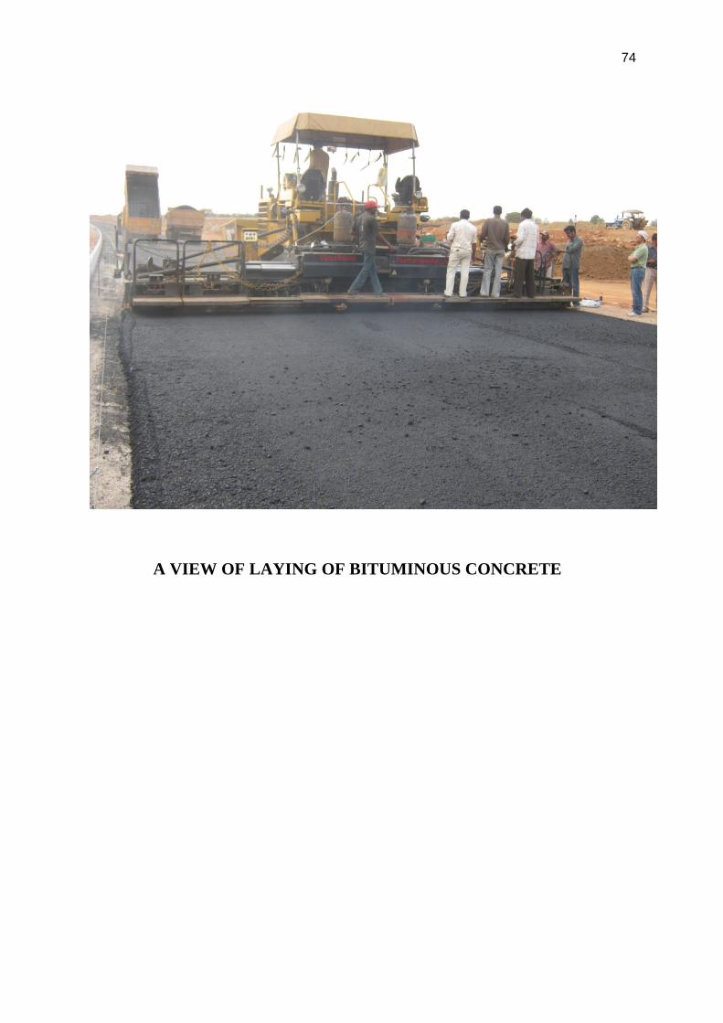
74
A VIEW OF LAYING OF BITUMINOUS CONCRETE

75
7. Plant and Machinery 7.1 Excavators: Excavators are heavy construction equipment consisting of a boom, stick, bucket and cab on a
rotating platform (known as the "house"). The house sits atop an undercarriage
with tracks or wheels. They are used for many purposes:
Digging of trenches, holes, foundations
Material handling
Brush cutting with hydraulic attachments
Forestry Work
Demolition
General grading/landscaping
Heavy lift, e.g. lifting and placing of pipes
The number of excavators used at the site are six.
Three types of excavators are used. They are:
i. Excavator 100
ii. Excavator 200
iii. Excavator 300
The 100,200 and 300 here represent the size of the bucket.

76
7.2 Motor Grader:
A motor grader is a construction machine with a long blade used to create a flat
surface. The grader's purpose is to "finish grade" the "rough grading" performed by heavy
equipment such as scrapers and bulldozers. Motor graders are commonly used in the
construction and maintenance of dirt roads and gravel roads. In the construction of paved
roads they are used to prepare the base course to create a wide flat surface for the asphalt or
bitumen to be placed on. Graders can produce inclined surfaces, to give cant (camber) to
roads.
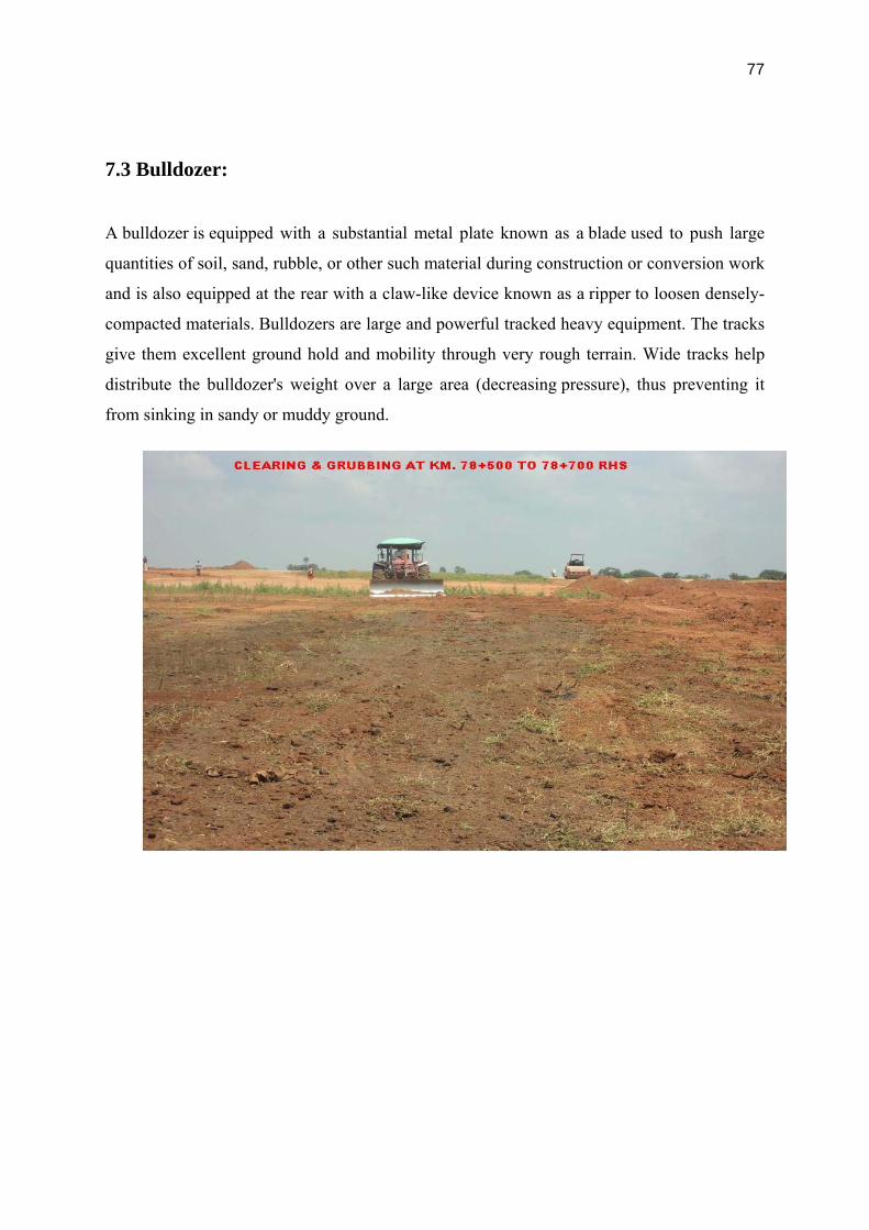
77
7.3 Bulldozer:
A bulldozer is equipped with a substantial metal plate known as a blade used to push large
quantities of soil, sand, rubble, or other such material during construction or conversion work
and is also equipped at the rear with a claw-like device known as a ripper to loosen densely-
compacted materials. Bulldozers are large and powerful tracked heavy equipment. The tracks
give them excellent ground hold and mobility through very rough terrain. Wide tracks help
distribute the bulldozer's weight over a large area (decreasing pressure), thus preventing it
from sinking in sandy or muddy ground.

78
7.4 Wheel Loader:
A wheel loader is a heavy equipment machine primarily used to load material such
as bitumen, demolition debris, dirt, gravel, logs, raw minerals, recycled material, rock, sand,
and woodchips into or onto another type of machinery such as a dump truck, conveyor belt. A
wheel loader has a front-mounted square wide bucket connected to the end of two arms to
scoop up loose material from the ground, such as dirt, sand or gravel, and move it from one
place to another without pushing the material across the ground. A wheel loader is commonly
used to move a stockpiled material from ground level and deposit it into an awaiting dump
truck or into an open trench excavation. wheel loaders are used mainly for uploading
materials into trucks, laying pipe, clearing rubble, and digging. A loader is not the most
efficient machine for digging as it cannot dig very deep below the level of its wheels, like an
excavator can.

79
7.5 Stone crusher:
A crusher is a machine designed to reduce large rocks into smaller rocks, gravel, or rock dust.
Crushers may be used to reduce the size, or change the form, of waste materials so they can
be more easily disposed of or recycled, or to reduce the size of a solid mix of raw materials
(as in rock ore), so that pieces of different composition can be differentiated.

80
7.6 WMM Plant:
This Central Mixing Plant for base and sub-base provides higher production with close
control on quality of mix and production cost. The Wet Mix Plant is specially designed to suit
the typical Indian site conditions. Capacity Range from 60 to 250 TPH. The plant can be
constructed to meet tailor made requirements.

81
7.7 Hot Mix Plant:
A hot mix plant is a plant used for the manufacture of asphalt, macadam and other forms of
coated roadstone, sometimes collectively known as blacktop.
The manufacture of coated roadstone demands the combination of a number
of aggregates, sand and a filler (such as stone dust), in the correct proportions, heated, and
finally coated with a binder, usually bitumen based or, in some cases, tar. The temperature of
the finished product must be sufficient to be workable after transport to the final destination.
A temperature in the range of 100 - 200 degrees Celsius is normal.

82
7.8 Dumpers:
A dumper is a truck used for transporting loose material such as sand, gravel,
and dirt for construction. A typical dump truck is equipped with a hydraulically operated
open-box bed hinged at the rear, the front of which can be lifted to allow the contents to be
deposited on the ground behind the truck at the site of delivery.
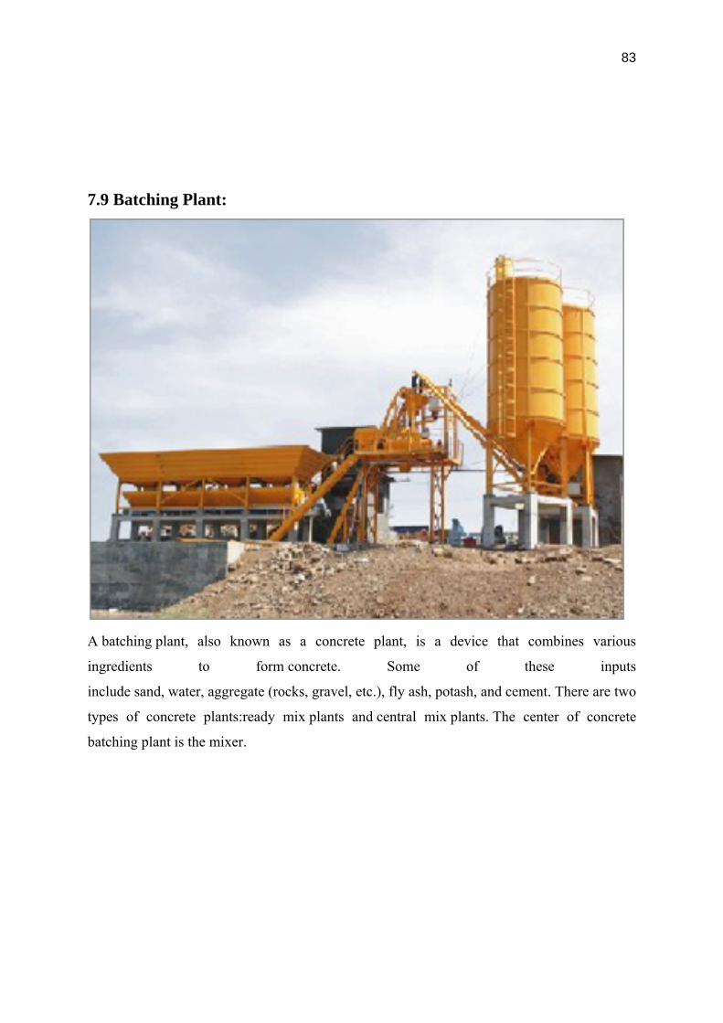
83
7.9 Batching Plant:
A batching plant, also known as a concrete plant, is a device that combines various
ingredients to form concrete. Some of these inputs
include sand, water, aggregate (rocks, gravel, etc.), fly ash, potash, and cement. There are two
types of concrete plants:ready mix plants and central mix plants. The center of concrete
batching plant is the mixer.

84
7.10 Sensor Paver:
Trusted for its performance with precision, Sensor Paver Finisher is one of the most reliable
products by Shiv Shakti Road Equipments. A mix of power, sensibility and sharpness. This
machine has been ultimate in its league unfailingly living upto the requirements and needs of
Road Constructing Company over the years. Presenting a unique mix of technology,
functionality, and quality, Sensor Paver Finisher guarantees best operational results.

85
8. Quality Management
8.1 Introduction:
The Globalization and developing Technology in the Construction Industry is leading to High
competition in the Current market. The best response to a competitive challenge in the
Construction Industry is to become more competitive. The best means of achieving this is by
improving the product quality and meeting the project schedule through a well designed
Quality Management system.
The Quality Management system shall focus on providing improved control on processes and
practices, thus enhancing customer satisfaction through its effective implementation.
8.2 Quality Policy, Quality System and Quality Strategy:
The Quality Policy is communicated and made understood at all level of the organization
through awareness program an display of the Quality Policy boards at all the Project
sites/departments. The Quality Policy shall be reviewed annually for continual improvement
and suitability to the purpose of the division.
Taking Quality Policy as guide, the quality objectives are established in related functions and
monitored in the monthly steering committee meetings and periodic Management Review
meetings.
Management review includes review of Quality objectives and specific policy statements
with the view to achieve Quality objectives and meeting the requirements of the policy
statement.

86
8.3 Quality Policy:
aspires to fulfill the expectations of our customer by a dedicated and organized approach,
which is amenable to skill and knowledge enhancement.
shall improve the competence of our Quality management System continually.
Focus is to accomplish this aim shall be on:
Effective design.
Effective Implementation of planning and Methodology.
Effective Supplier Management.
Proficient Management of Workforce.
Training and development of Human Resource.
8.4 Quality System: The Quality System has been designed to ensure that the Quality Policy, objectives and the
requirements of ISO 9001:2008 are implemented. The system has been determined in terms
of the following main processes.
1. Estimation, Costing and Tendering
2. Design and Engineering
3. Quality planning and Control
4. Planning, Monitoring and Control
5. Plant and Machinery provision
6. Project Operation
7. Commercial, Contract and Procurement
8. Personnel and training
9. Finance
10. Quality System

87
Structure of Quality Management System documentation
Quality management
System manual
Other Quality Documents (Standards, Records,
Guidelines, Check lists etc)
Quality Process and Procedure
Manual
Project Quality Plan
QUALITY POLICY
8.5 Quality Strategy: Implementation of the Quality Management system and its effectiveness is ascertained
by periodical monitoring as well as by structured internal quality audit and corrective and
preventive action to ensure improvement in effectiveness of the Quality system in operation.
A continuous process of feasible Technology up gradation and value analysis is initially
targeted at persisting un solved non-conformities to be attended to as well as potential
problems.

88
Management review of the quality system is conducted periodically, to check for continued
suitability for effectiveness, towards meeting the requirement of the organization’s Quality
Policy and objectives.
The integrity of Quality Management System is ensured when changes are planned and
implemented.
8.6 Planning: This Project Quality Manual is the document which details the Quality System to be planned,
established, implemented and maintained as part of the contract for the road works for the
project.
The Project Quality Plan consists of the following:
(i) The Project Quality Statement of the company.
(ii) Project Specific Details including Organization and System Element
Description.
(iii) Inspection and Test Plans (including Construction Process Flowcharts and
Quality Verification Checklists).
(iv) Project specific Procedures as required by the contract specification /
concession agreement.
The inspection and test plan shall identify necessary inspections and tests to verify
conformance of the work during performance of the identified project tasks. It shall include
acceptance criteria and details for performance of inspection and test activities, as applicable.
8.7 Control:
Control shall be achieved by implementing the requirements of the Project Quality Manual
including construction process controls, inspection and test plan and audit requirements.
Continuous monitoring and the investigation of timely corrective action shall form the basis
of control. System Element Descriptions shall detail the methods by which the quality system
is controlled. The agreed Inspection and Test Plans shall be used for controlling the work and
detecting nonconformance.

89
8.8 Verification:
Verification processes shall be established to ensure that the planning and controls have been
effective and the Quality System and constructed works conform to the specified
requirements. The outcome of all verification activities shall be documented and maintained
as quality records. Records of conformance shall be available for inspection by the
Concessionaire’s Representative / IE upon request to provide evidence of the outcome of
activities undertaken to achieve conformance.
8.9 Quality Management in Construction and Reporting
8.9.1 Management Responsibilities:
The Head – Project Operations (Roads) has the overall responsibility for construction of the
project, ensuring Customer (Concessionaire) satisfaction. The Chief Project Manager of
Project will be in charge of this Project and will be reporting to the Head – Project Operations
(Roads). Project Quality Plan will be implemented by the Chief Project Manager. The
Project QA/QC team will interact with QA /QC team of Concessionaire for review of
material tests, mix designs and QA/QC procedures as per the Project Quality Plan and reports
functionally to Head – QA/QC H.O. The Head – QA/QC H.O will report to the top
management and act independently to implement QA policy of the Organization. He has the
responsibility for formulating, implementing, reviewing, monitoring, verifying and assessing
the effectiveness of Quality Assurance program. He has also been delegated the authority to
take corrective measures in case of any significant quality related problems are noticed, with
the intimation to the Chief Project Manager.
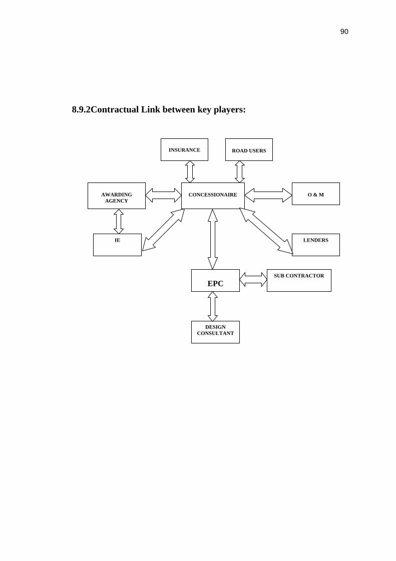
90
8.9.2Contractual Link between key players:
INSURANCE
CONCESSIONAIRE
AWARDING
AGENCY
O & M
IE
EPC
LENDERS
SUB CONTRACTOR
DESIGN CONSULTANT
ROAD USERS

91
8.9.3 Organization set up of the Project:
Concessionaire
EPC Contractor Site HQ
Design Consultant
Sub Contractor
Execution
Survey
Quality
Highway
Structure
HSE
Plant & Machinery
Client
Business Development
Engineering
Quality
PMC
Project Operation
C & C
HSE
Finance
HR
PMC
QS
C & C
F & A
Admin
HR
Independent Engineer Employer
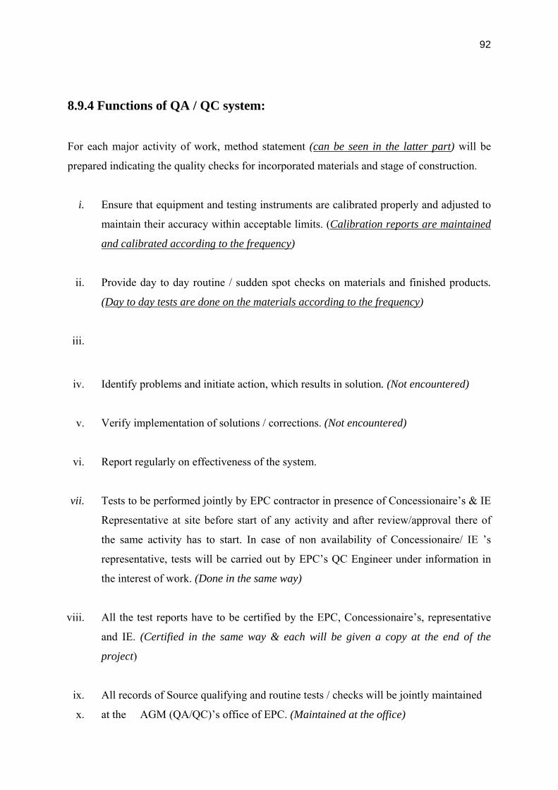
92
8.9.4 Functions of QA / QC system:
For each major activity of work, method statement (can be seen in the latter part) will be
prepared indicating the quality checks for incorporated materials and stage of construction.
i. Ensure that equipment and testing instruments are calibrated properly and adjusted to
maintain their accuracy within acceptable limits. (Calibration reports are maintained
and calibrated according to the frequency)
ii. Provide day to day routine / sudden spot checks on materials and finished products.
(Day to day tests are done on the materials according to the frequency)
iii.
iv. Identify problems and initiate action, which results in solution. (Not encountered)
v. Verify implementation of solutions / corrections. (Not encountered)
vi. Report regularly on effectiveness of the system.
vii. Tests to be performed jointly by EPC contractor in presence of Concessionaire’s & IE
Representative at site before start of any activity and after review/approval there of
the same activity has to start. In case of non availability of Concessionaire/ IE ’s
representative, tests will be carried out by EPC’s QC Engineer under information in
the interest of work. (Done in the same way)
viii. All the test reports have to be certified by the EPC, Concessionaire’s, representative
and IE. (Certified in the same way & each will be given a copy at the end of the
project)
ix. All records of Source qualifying and routine tests / checks will be jointly maintained
x. at the AGM (QA/QC)’s office of EPC. (Maintained at the office)

93
xi. Monthly Project QA report will be prepared by project AGM (QA/QC), summarizing
the activities of QA department which is to be submitted to Concessionaire’s
Management. (Monthly reports are updated)
xii. Project Manager / AGM (QA/QC) through his representative at site will point out the
non-conformity of Product/Work to standards & Specifications if any, to the
contractor’s authorized representative in writing and a copy of the same to be sent to
the Chief Project Manager for getting the work done as per quality standard required
as specified in concession agreement, quality specifications or drawings.
xiii. The Client, Concessionaire, Independent Engineer, EPC Contractors, Sub contractors,
Material supplier and Manufacturer, each form a link of the quality chain. The
strength of this chain is dependent on each and every link. The AGM (QA/QC) is to
keep a continuous watch on this chain and spot the weak link before it snapped.
8.9.5 Quality Management Reports:
The AGM (QA/QC) at site shall prepare a monthly Quality Management Report for review
by the Chief Project Manager / Project Manager. The Quality Report shall be subdivided into
the following headings:
Summary of Inspection and Test Activities. (Field & Laboratory)
Registers of Nonconformance & Corrective Action.
Status of Approvals of all Materials.
Pending approvals by the Concessionaire/ IE.
Items of specific concern.
General Notes.

94
8.9.6 Distribution of the Quality Management Report shall be as follows:
Concessionaire
Chief Project Manager
Project Manager
Head (QA/QC) (HO)
The Quality Management Report shall be submitted to the CPM within one week of the close
of the monthly reporting period and in turn Site shall forward this to Head Office (QA)
within 3rd of the every month for record and distribution to the respective section in charge
for record and action required if any.
8.9.7 Management Reviews:
The operation and effectiveness of the Project Quality Plan shall be regularly reviewed by
Management Review meetings held once in Two months for the duration of the project. The
monthly Quality Management Report together with Audit Reports shall form the basis of the
review.
The Management Review meetings will be attended by the CEO, Head – Project Operations
(Roads), Management Representative, and Project Management team. Minutes of the
management review meeting will be taken by the MR. He shall be responsible to prepare
and distribute minutes to the members of the review Committee for their information and
action.
8.9.8 Monthly Progress Reports:
The Monthly progress shall be prepared at site and submitted to the Concessionaire as per
requirements of contract agreement. The detailed format for the report contained all the
activities of the month, major achievements, mile stone achieved, progress, quality control
reports, problems, issues etc. The contents of the Monthly progress report shall be as per the
Contract agreement.

95
8.9.9 PROGRESS CONTROL:
The EPC Contractor is required to undertake its activities in accordance with the approved
work program. Each month the contractor shall indicate the actual work completed as
compared to work scheduled. In the event portions of the work are in danger of being
delayed, or actually are delayed, the contractor is to determine a plan for remedial action.
8.10 Quality Control and Assurance in Construction 8.10.1 Quality Control of Road Works:

96
8.11 CONSTRUCTION QUALITY CONTROL:
8.11.1 General:
Quality control of materials forms an integral part of the overall construction and supervision
function. Taken properly into account, it provides the link between the design and the
finished works.
Testing of construction materials is carried out for a variety of reasons and purposes
including:
• Screening Tests (e.g. choosing a borrow source, an aggregate supplier, a manufacturer
/ supplier of cement etc.)
• Control Tests (e.g. sampling and testing of cement material delivered to site to
confirm adherence to project specifications and to confirm manufacturer’s Test
Certificate)
• Audit Tests to verify independently the reported properties of materials
• Trial Mixes (selection of appropriate concrete mix designs, design of bituminous
mixtures etc.)
• Acceptance Tests (e.g. testing of cubes cast of produced concrete to confirm that
required strength is achieved and is consistent)
• Special testing as may be deemed necessary and prudent.
Suppliers of manufactured materials such as Cement, Steel, Bitumen, Bearings, Expansion
Joints, Road Furniture etc. shall be screened based on submissions, review of sample
Manufacturer’s Test Certificates and experience on previous projects of the manufacturer.
Independent testing by third party in the presence of Concessionaire’s / IE may also be
required.
Control and approval of construction materials shall be based on the following:
Test reports for materials tested , such as cement, sand, water, soil, aggregates
and bitumen; and
Manufacturer’s certificates for materials such as steel, cement, admixtures etc.

97
The details of input materials should be recorded in a Materials Register. All test results shall
be entered into a testing register maintained at site laboratory, with an indication of
conformance/non-conformance. A format for testing register is given.
This section hereinafter provides an overview of control requirements for materials, including
site testing and manufacturers’ certification.
Laboratory at locations shall be set up by the EPC/Sub contractor. The laboratory will be
equipped with sufficient number of modern and efficient equipment suitable to carry out the
tests prescribed for different materials and work according to the concession agreement and
specifications.
• The laboratory will be manned by a qualified Material Engineer assisted by
experienced Engineers , Technicians, Laboratory helpers and the set-up will be
got approved by the Concessionaire.
• Tests shall be carried out Quality Controls on the materials and work to the
frequency in subsequent paragraphs. In the absence of clear indications about
method and or frequency of tests for any item, the direction of the
Concessionaire’s representative and IE shall be followed.
• For satisfying himself about the Quality of the materials and work, Quality
Control tests will also be conducted by the Concessionaire’s representative / IE ,
(by himself, by his Quality Control units or by any other agencies deemed fit by
him), generally to the frequency set forth herein under. Additional tests may also
be conducted where in the opinion of the Concessionaire’s representative /
Independent Engineer need for such tests exists.
• Provision of necessary cooperation and assistance in obtaining the samples for test
and carrying out the field test as required by the Concessionaire’s representative
from time to time. This may include provision of labours, attendance, assistance in
packing and dispatching any other assistance considered necessary in connection
with the test.

98
• For the work of embankment, sub grade and pavement, construction of subsequent
layer of some or other material over the finished layer will be done after obtaining
approval from the Concessionaire. Similar approval from the Concessionaire will
be obtained in respect of all other items of works to proceeding with the next stage
of construction.
• Defective /Inferior quality of work shall be modified in the procedure of work, if
found necessary, as directed by IE during inspection. Works falling short of
quality at our own cost and as directed by the IE.
• All the tests to be conducted at laboratory and at site shall be documented as per
the format specified. Usually the documentation shall be maintained in such a
fashion that it shall be very easy traceable with a specific RFI No. mentioned with
date in schematic diagram for each Structure and layer chart for Roads and in turn
this shall be filed in KM basis for Roads with Bituminous and Non-Bituminous in
a separate file / volume as a lot with several sub lot. For structures each structure
shall be defined as a single lot.
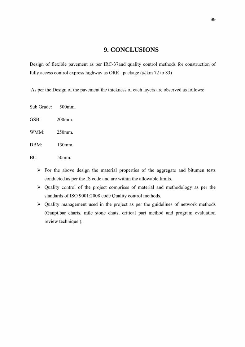
99
9. CONCLUSIONS
Design of flexible pavement as per IRC-37and quality control methods for construction of
fully access control express highway as ORR –package (@km 72 to 83)
As per the Design of the pavement the thickness of each layers are observed as follows:
Sub Grade: 500mm.
GSB: 200mm.
WMM: 250mm.
DBM: 130mm.
BC: 50mm.
For the above design the material properties of the aggregate and bitumen tests
conducted as per the IS code and are within the allowable limits.
Quality control of the project comprises of material and methodology as per the
standards of ISO 9001:2008 code Quality control methods.
Quality management used in the project as per the guidelines of network methods
(Ganpt,bar charts, mile stone chats, critical part method and program evaluation
review technique ).

100
References:
Highway Engineering by S.K.Khanna and Justo.
MORT and H specifications.
Traffic engineering and transport planning by Dr.L.R.Kadiyali

101
APPENDIX