design considerations for usb type c power delivery … considerations for usb type c power...
TRANSCRIPT
1
Design Considerations for USB type C Power DeliveryBrian King
What will I get out of this session?
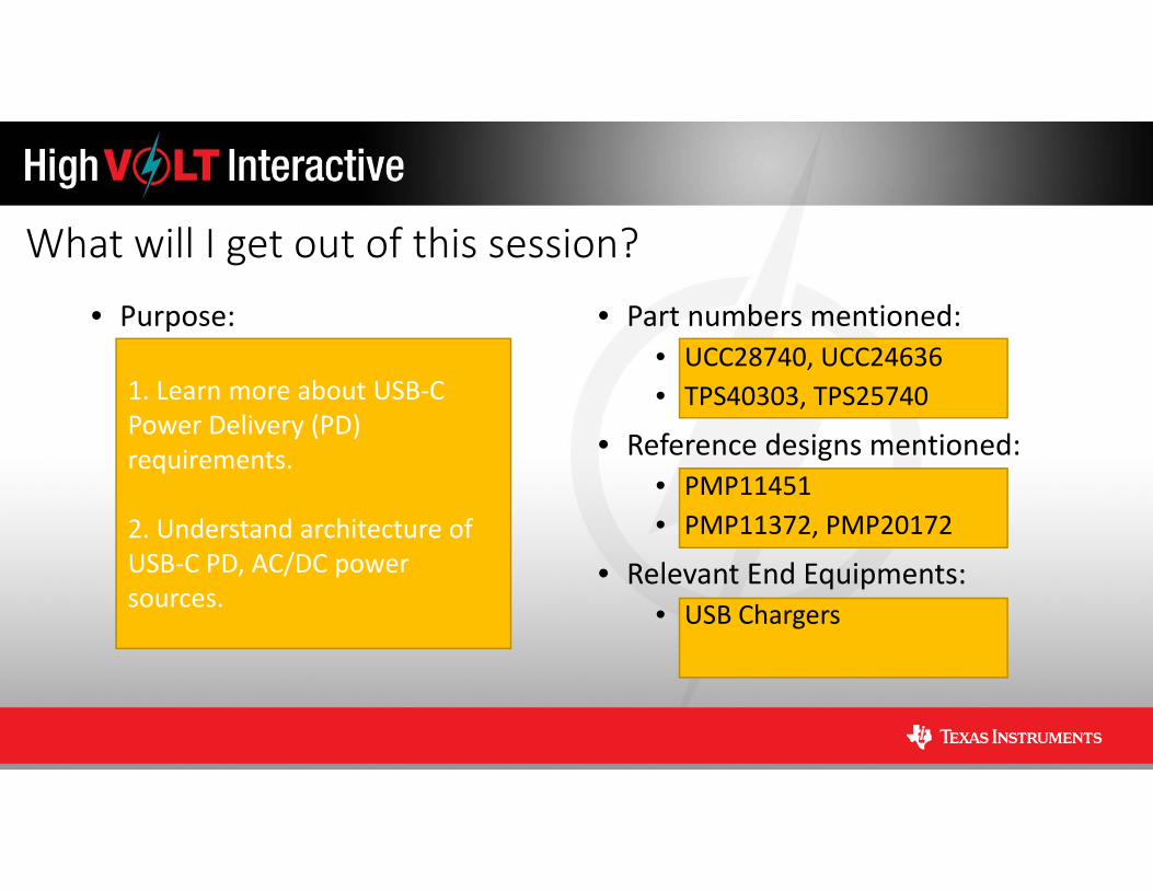
• Purpose: • Part numbers mentioned:• UCC28740, UCC24636• TPS40303, TPS25740
• Reference designs mentioned:• PMP11451• PMP11372, PMP20172
• Relevant End Equipments:• USB Chargers
1. Learn more about USB‐C Power Delivery (PD) requirements.
2. Understand architecture of USB‐C PD, AC/DC power sources.
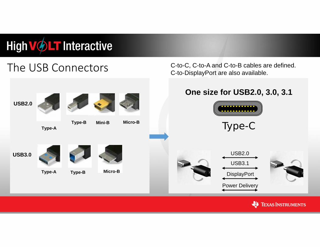
The USB Connectors
USB2.0
USB3.0
Type-A
Type-A
Type-B
Type-B Micro-B
Micro-BMini-B
One size for USB2.0, 3.0, 3.1
USB2.0
DisplayPort
Power Delivery
USB3.1
C-to-C, C-to-A and C-to-B cables are defined.C-to-DisplayPort are also available.
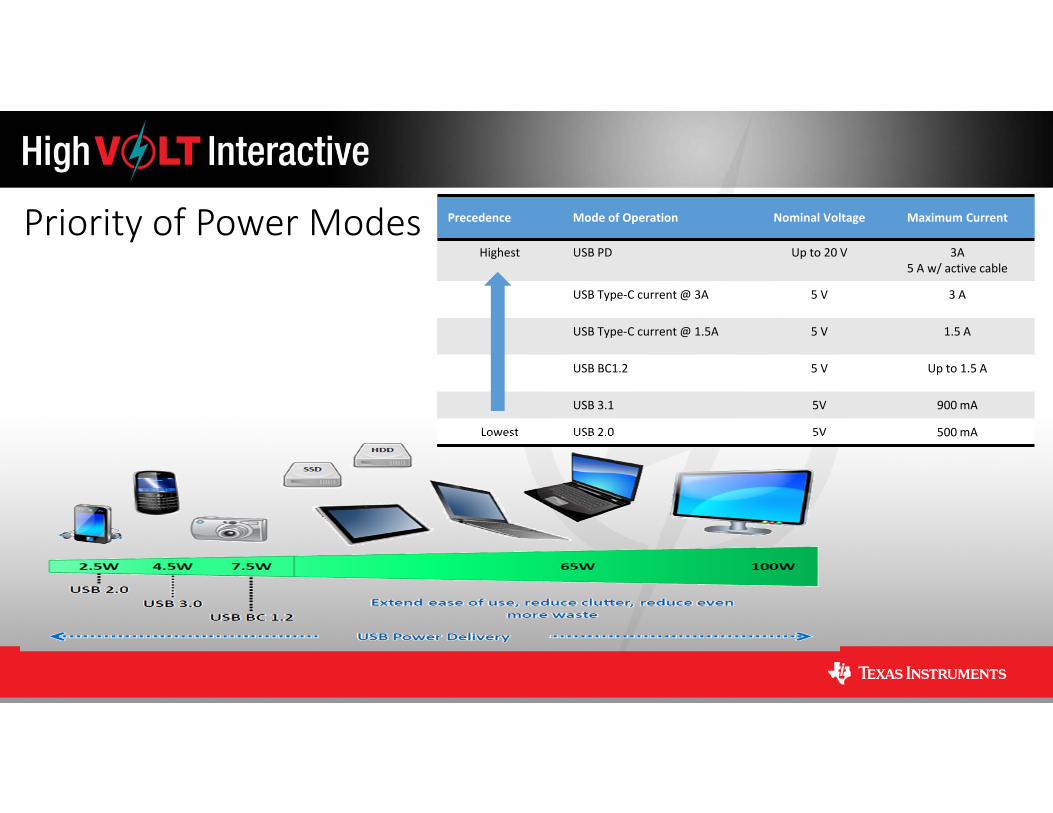
Priority of Power Modes Precedence Mode of Operation Nominal Voltage Maximum Current
Highest USB PD Up to 20 V 3A5 A w/ active cable
USB Type‐C current @ 3A 5 V 3 A
USB Type‐C current @ 1.5A 5 V 1.5 A
USB BC1.2 5 V Up to 1.5 A
USB 3.1 5V 900 mA
Lowest USB 2.0 5V 500 mA
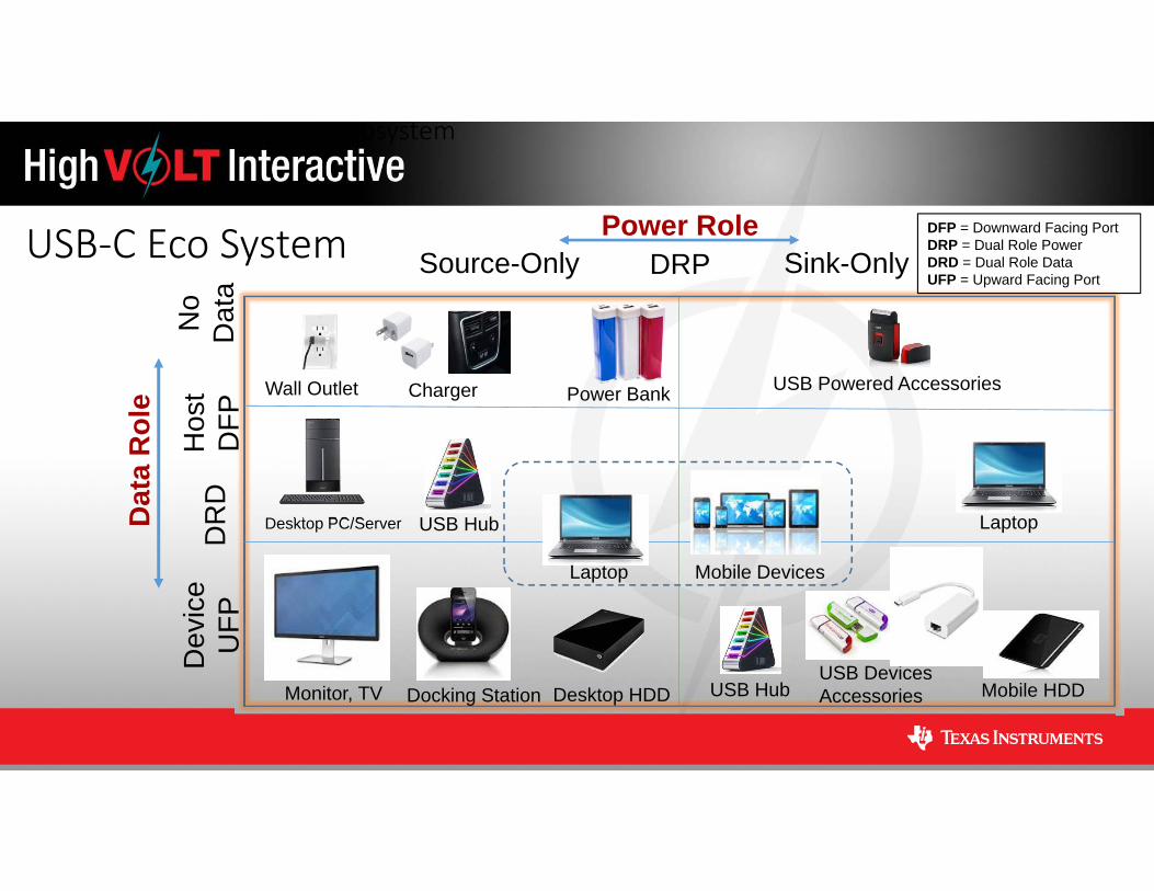
USB‐C Eco System
The USB Type‐C Ecosystem
Power Role
Dat
a R
ole
Dev
ice
UFP
Hos
tD
FPSource-Only Sink-Only
Desktop PC/Server
Mobile Devices
DR
D
Power Bank
Monitor, TV Docking Station
Wall Outlet Charger
USB HubUSB DevicesAccessories
Laptop
Laptop
Desktop HDD Mobile HDD
USB Hub
No
Dat
a
USB Powered Accessories
DFP = Downward Facing PortDRP = Dual Role PowerDRD = Dual Role DataUFP = Upward Facing Port
DRP

Focus on Source‐Only Application• There are many different applications that require different silicon solutions under the USB Type‐C umbrella.
o Laptops, docking station, monitors, tablets, etc.
• One benefit of the wide‐spread adoption of this open standard is a realistic path to a universal charger and e‐waste reduction.
o One connector instead of the proliferation of different adaptors for different devices
o 300,000 tons of e‐waste goes to landfills every year (according to UN)

Monotonic Incremental Power Rule• USB PD enforces voltage profiles as a function of max power.
• e.g., if the power advertised on a port > 27W; 5V, 9V, and 15V shall be offered.
• Other voltages may be offered, but must not exceed highest required voltage rail
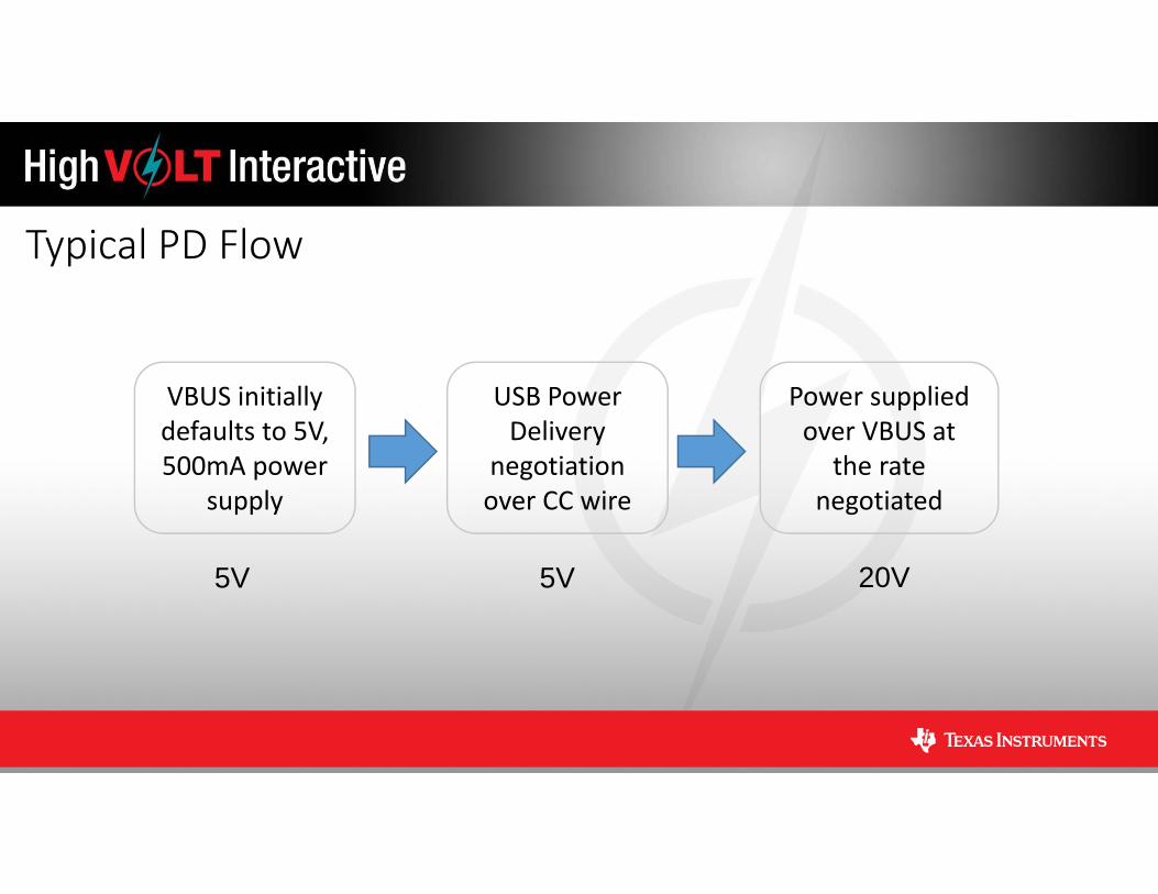
Typical PD Flow
VBUS initially defaults to 5V, 500mA power
supply
USB Power Delivery
negotiation over CC wire
Power supplied over VBUS at
the rate negotiated
5V 5V 20V
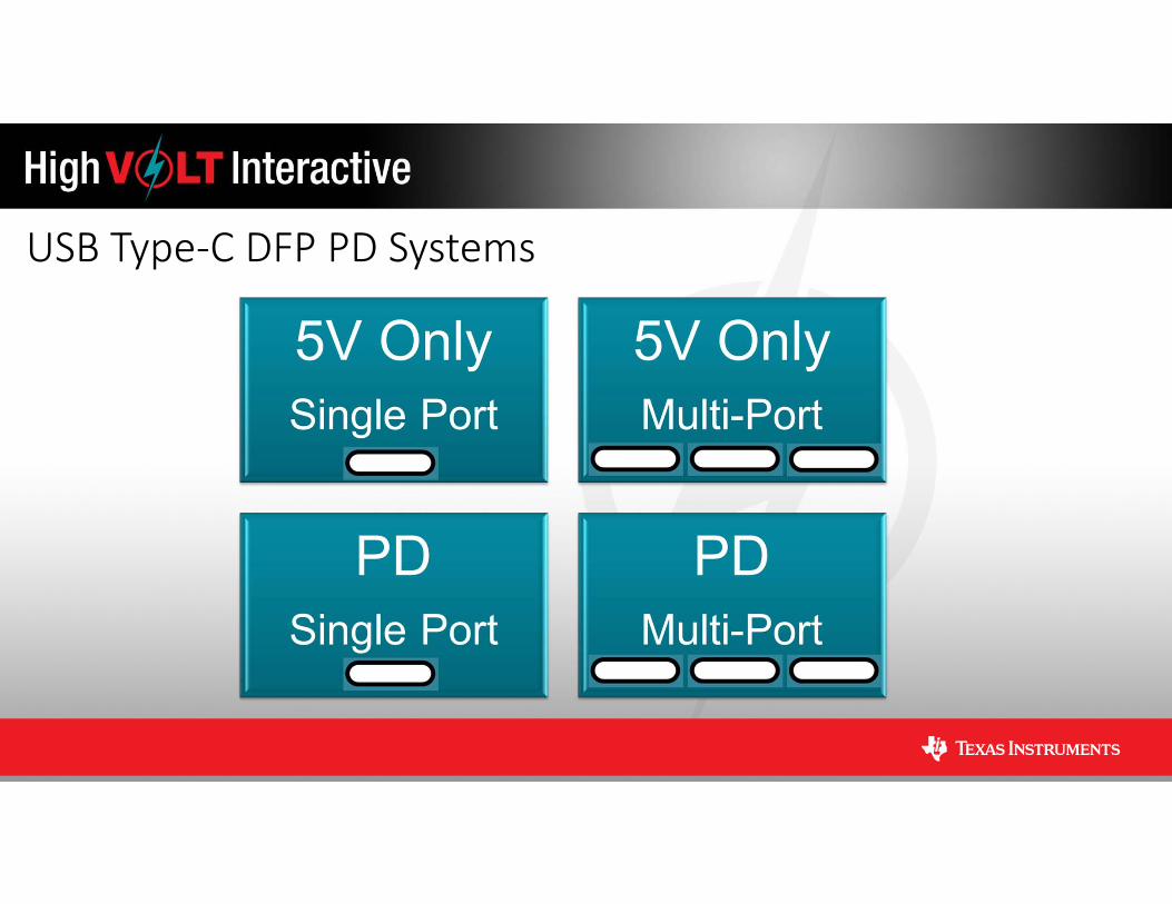
USB Type‐C DFP PD Systems
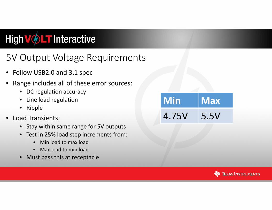
5V Output Voltage Requirements• Follow USB2.0 and 3.1 spec• Range includes all of these error sources:
• DC regulation accuracy• Line load regulation• Ripple
• Load Transients: • Stay within same range for 5V outputs• Test in 25% load step increments from:
• Min load to max load • Max load to min load
• Must pass this at receptacle
Min Max4.75V 5.5V
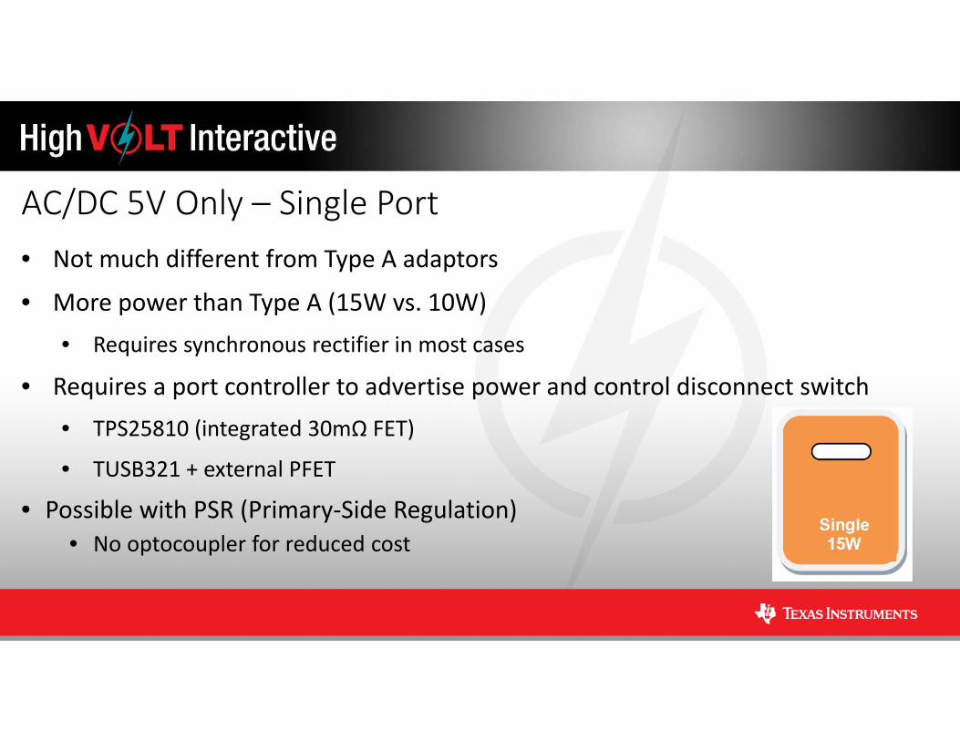
AC/DC 5V Only – Single Port• Not much different from Type A adaptors
• More power than Type A (15W vs. 10W) • Requires synchronous rectifier in most cases
• Requires a port controller to advertise power and control disconnect switch• TPS25810 (integrated 30mΩ FET)
• TUSB321 + external PFET
• Possible with PSR (Primary‐Side Regulation)• No optocoupler for reduced cost
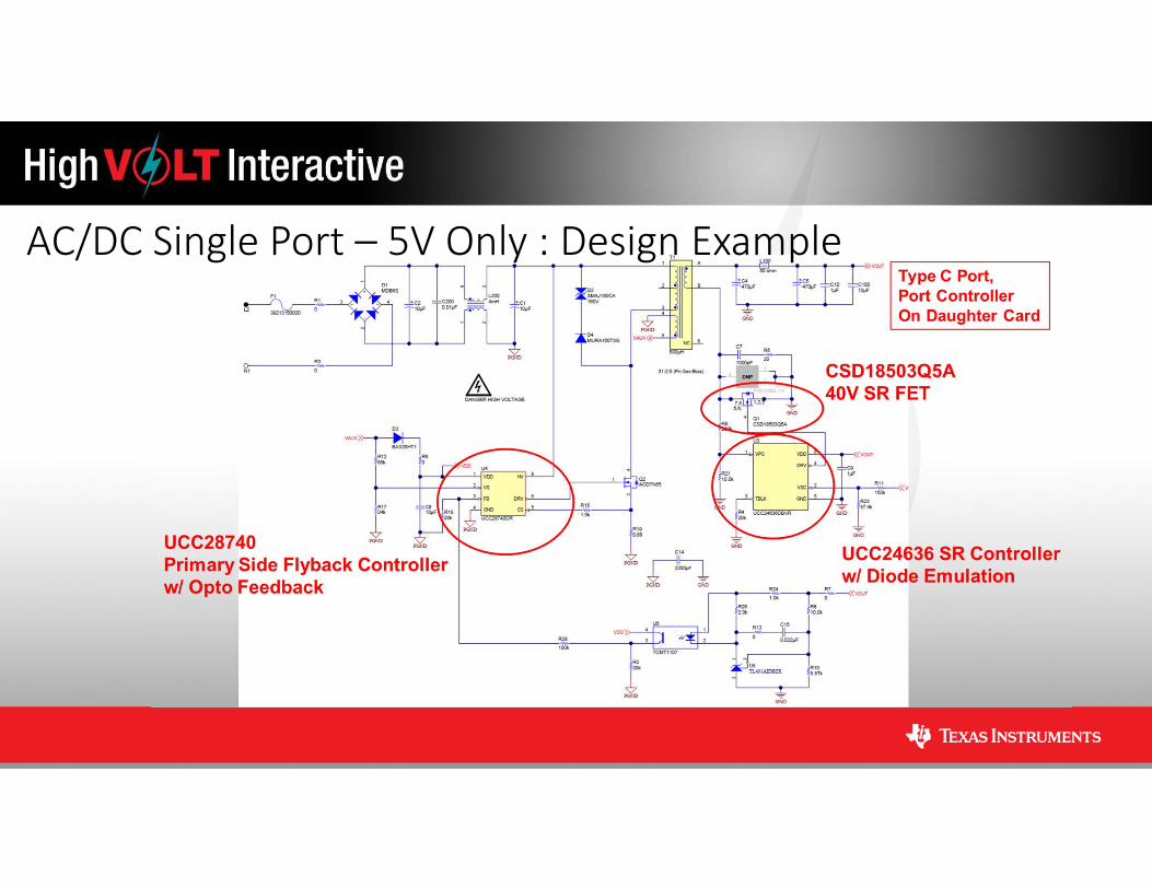
AC/DC Single Port – 5V Only : Design Example
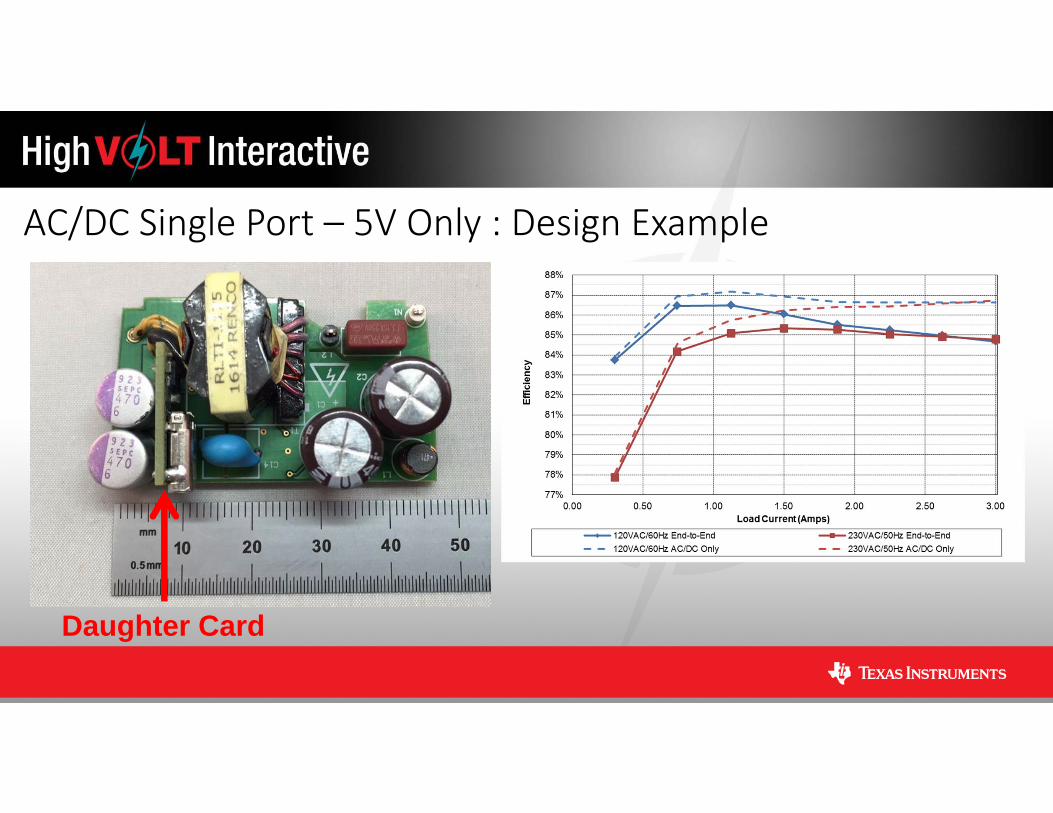
AC/DC Single Port – 5V Only : Design Example
Daughter Card

AC/DC 5V Only – Multi‐Port• Can be a mixture of Type A and Type C ports
• Each Type C port needs a port controller
• Total power level >15W • Definitely needs SR
• Secondary‐side regulation recommended• Difficult to maintain regulation on all ports

AC/DC Multi‐Port – 5V Only : Design Example
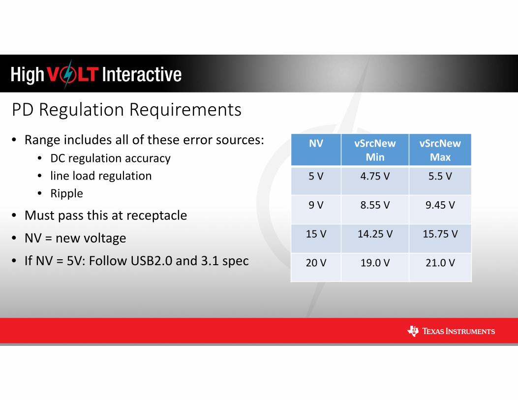
PD Regulation Requirements• Range includes all of these error sources:
• DC regulation accuracy• line load regulation• Ripple
• Must pass this at receptacle
• NV = new voltage
• If NV = 5V: Follow USB2.0 and 3.1 spec
NV vSrcNewMin
vSrcNewMax
5 V 4.75 V 5.5 V
9 V 8.55 V 9.45 V
15 V 14.25 V 15.75 V
20 V 19.0 V 21.0 V
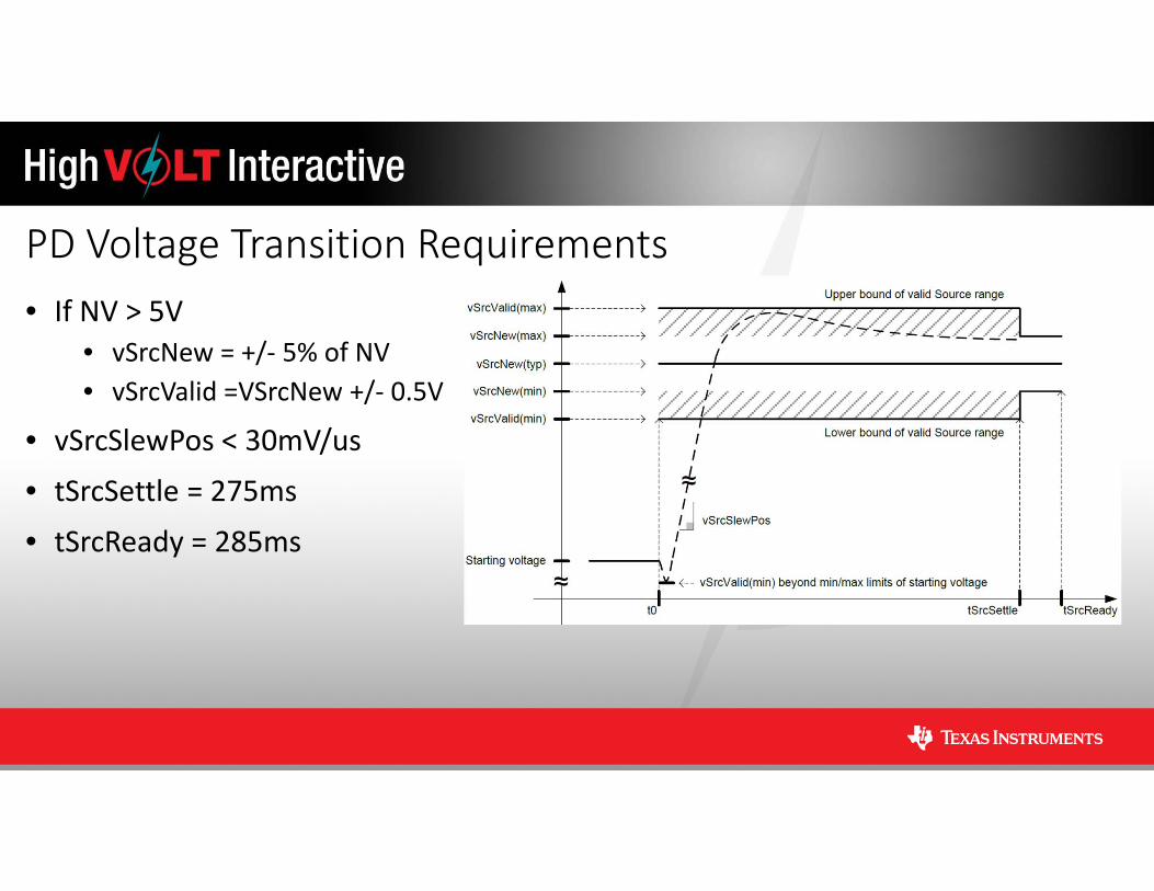
PD Voltage Transition Requirements• If NV > 5V
• vSrcNew = +/‐ 5% of NV• vSrcValid =VSrcNew +/‐ 0.5V
• vSrcSlewPos < 30mV/us
• tSrcSettle = 275ms
• tSrcReady = 285ms
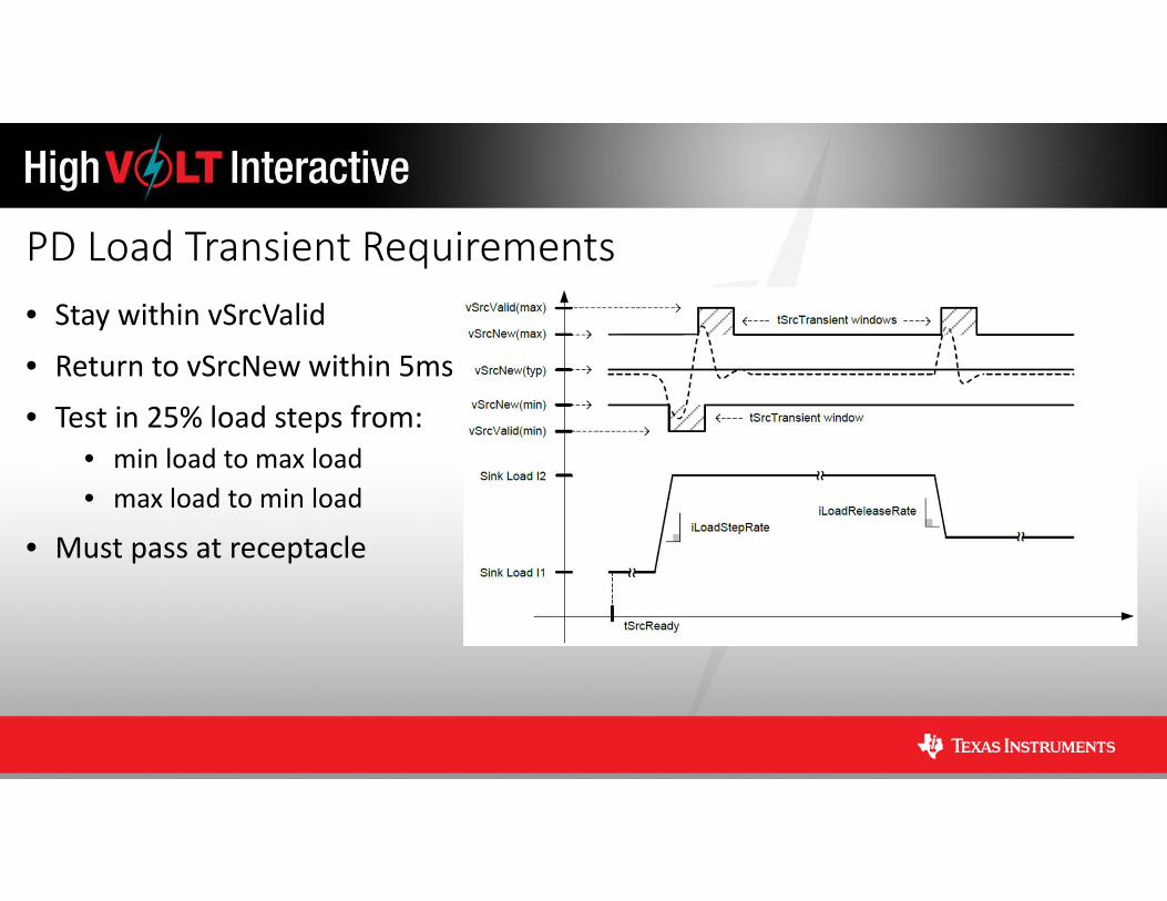
PD Load Transient Requirements• Stay within vSrcValid
• Return to vSrcNew within 5ms
• Test in 25% load steps from:• min load to max load • max load to min load
• Must pass at receptacle
AC/DC PD – Single Port• Flyback is the best topology choice:
• Tolerant of wide output voltage variations• Simple and low cost• Good efficiency and low standby power
• Secondary‐side regulation is required to adjust output voltage
• Aux winding voltage is proportional to output voltage• VDD to the primary controller may need to be clamped
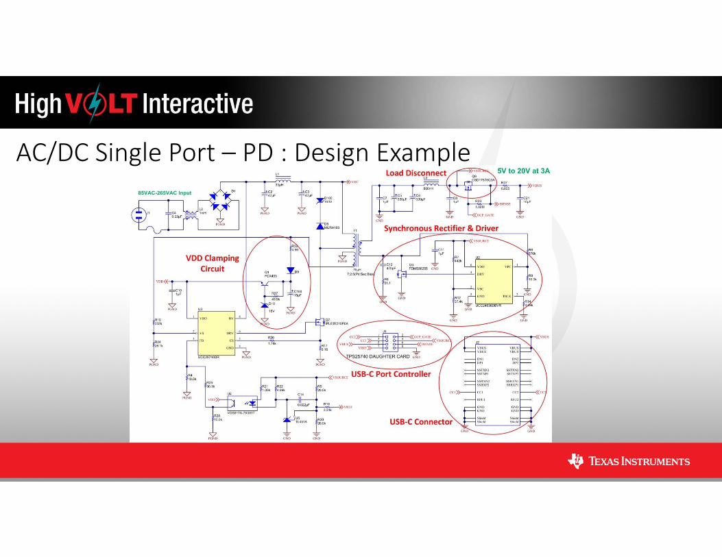
AC/DC Single Port – PD : Design Example
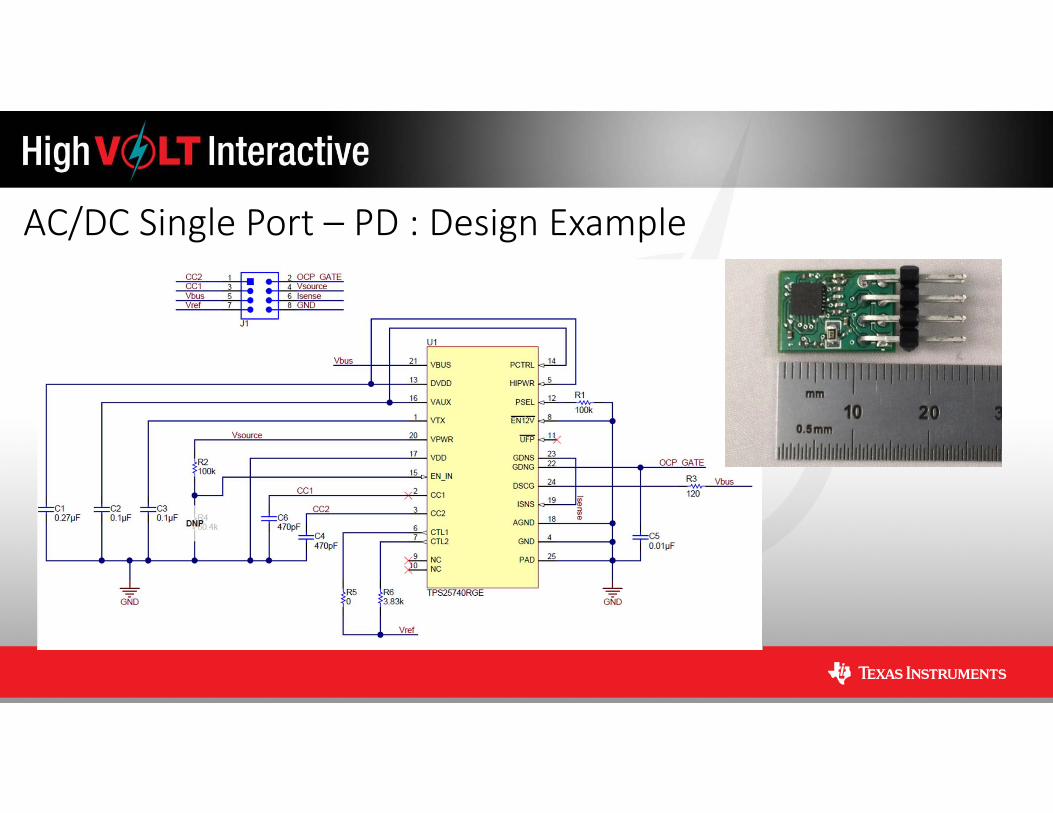
AC/DC Single Port – PD : Design Example
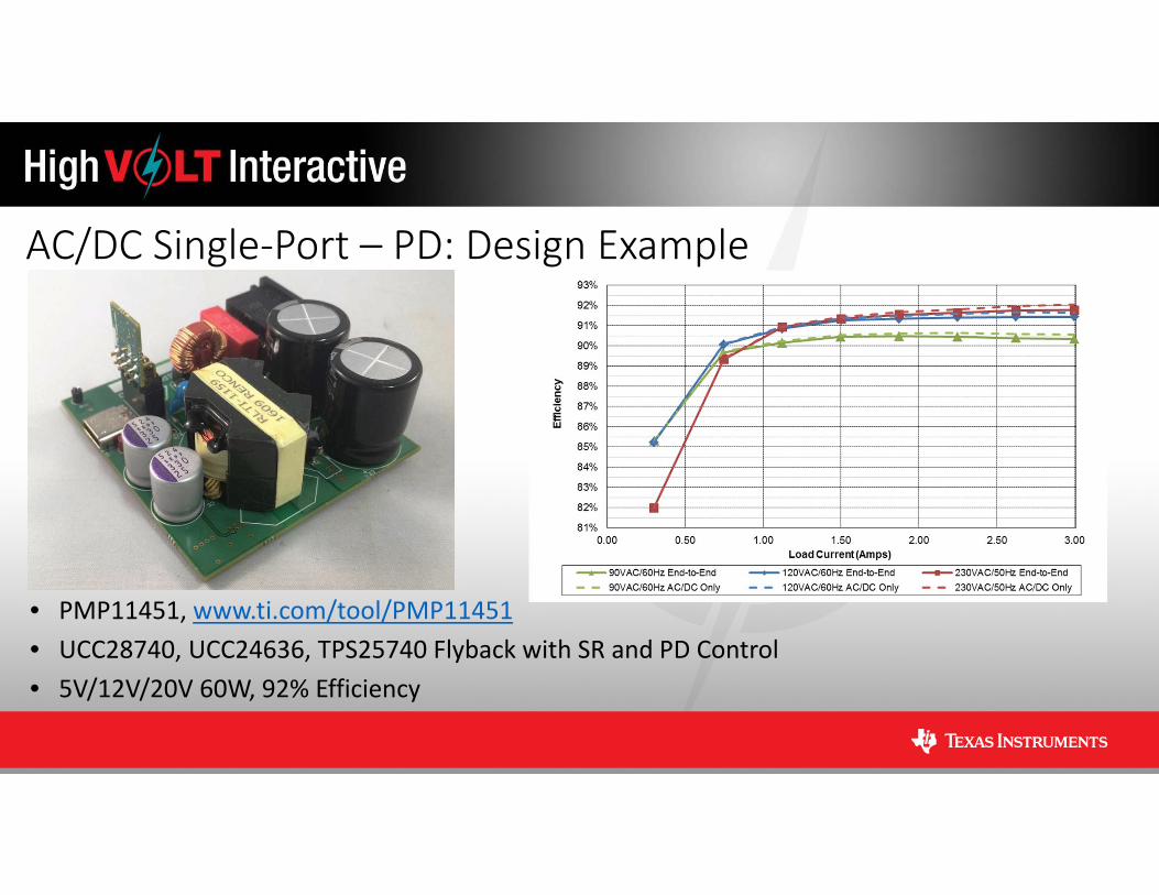
AC/DC Single‐Port – PD: Design Example
• PMP11451, www.ti.com/tool/PMP11451• UCC28740, UCC24636, TPS25740 Flyback with SR and PD Control • 5V/12V/20V 60W, 92% Efficiency
AC/DC PD – Multi‐Port• Complicated because…
• Must support multiple voltages simultaneously
• But, luckily…• Power/voltage contracts can be renegotiated at any time
• Possible architectures:• Generate multiple voltage rails and mux to ports• Generate intermediate bus and post regulate each port
• Power path management• Simple two port systems can be designed using built‐in features of TPS25740• 3+ port systems require a microprocessor
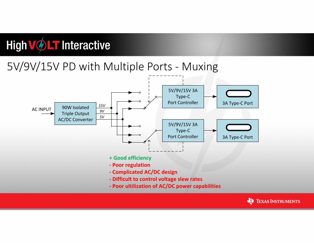
5V/9V/15V PD with Multiple Ports ‐Muxing
3A Type‐C Port90W IsolatedTriple Output
AC/DC Converter
5V/9V/15V 3A Type‐C
Port ControllerAC INPUT
3A Type‐C Port
5V/9V/15V 3A Type‐C
Port Controller
5V9V15V
+ Good efficiency‐ Poor regulation‐ Complicated AC/DC design‐ Difficult to control voltage slew rates‐ Poor ultilization of AC/DC power capabilities
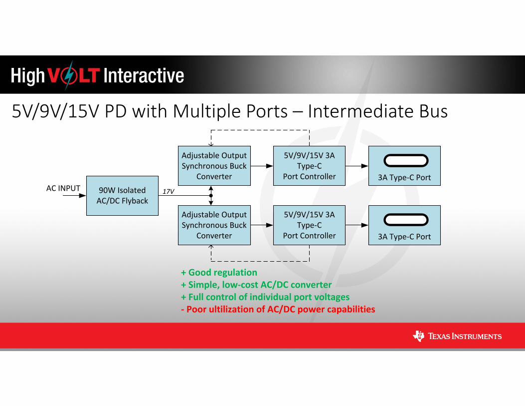
5V/9V/15V PD with Multiple Ports – Intermediate Bus
3A Type‐C Port90W IsolatedAC/DC Flyback
5V/9V/15V 3A Type‐C
Port ControllerAC INPUT
3A Type‐C Port
5V/9V/15V 3A Type‐C
Port Controller
17V
+ Good regulation+ Simple, low‐cost AC/DC converter+ Full control of individual port voltages‐ Poor ultilization of AC/DC power capabilities
Adjustable Output Synchronous Buck
Converter
Adjustable Output Synchronous Buck
Converter
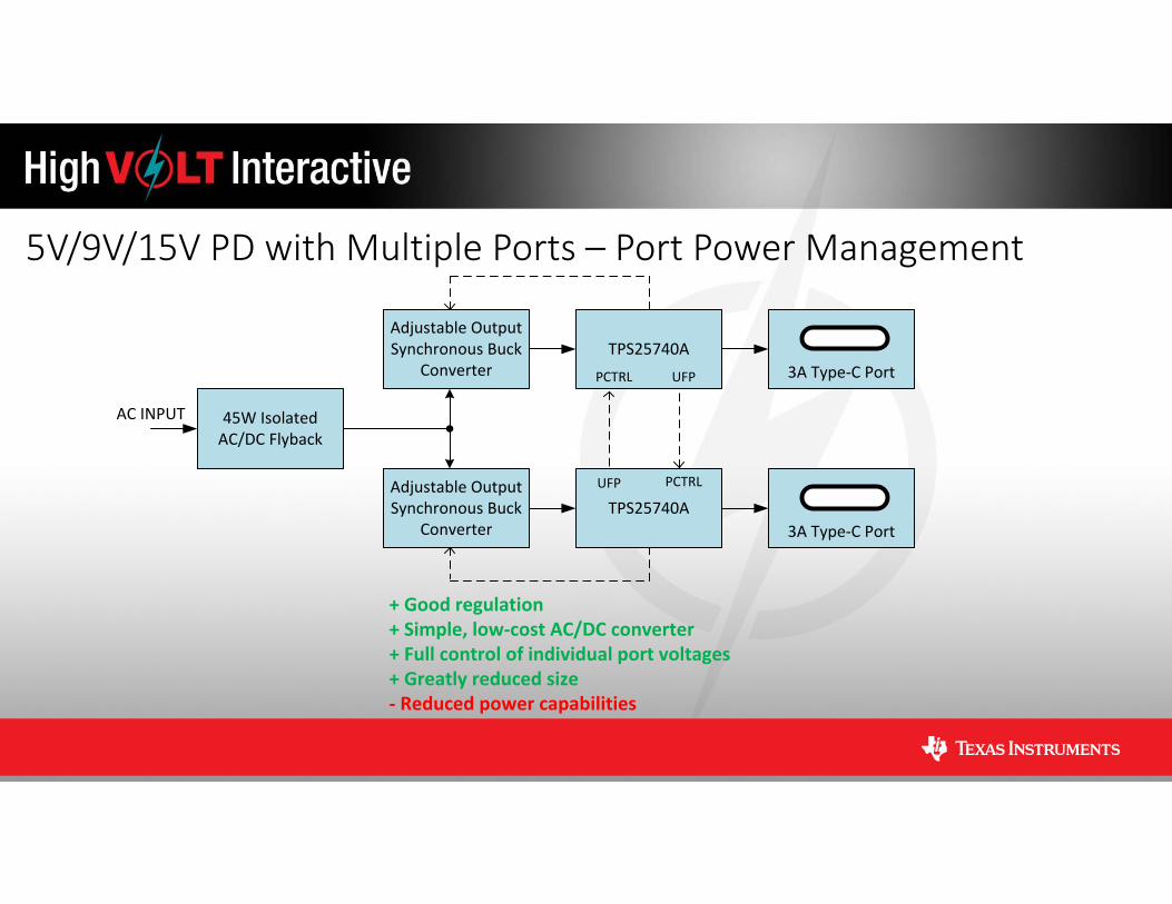
5V/9V/15V PD with Multiple Ports – Port Power Management
3A Type‐C PortTPS25740A
3A Type‐C PortTPS25740A
Adjustable Output Synchronous Buck
Converter
Adjustable Output Synchronous Buck
Converter
UFP
UFPPCTRL
PCTRL
45W IsolatedAC/DC Flyback
AC INPUT
+ Good regulation+ Simple, low‐cost AC/DC converter+ Full control of individual port voltages+ Greatly reduced size‐ Reduced power capabilities

AC/DC Multi‐Port – PD: Design Example
• PMP11372, www.ti.com/tool/PMP11372• UCC28740, UCC24636, Flyback with SR• 17V/36W, 93% Efficiency
• PMP20172, www.ti.com/tool/PMP20172• TPS40303, TPS25740, Sync Buck & PD Control• 5V/9V/15V 36W, >98% Efficiency
Conclusions• Understand the Type‐C and PD rules before designing• 5V only systems are fairly straight forward• Single port PD solutions require:
• Clamping circuit on VDD• Port controller• Disconnect FET
• Multiple port PD solutions benefit from:• Two stage approach• Smart port power management• High efficiency• High power density