design evaluation and optimization of connecting rod
TRANSCRIPT
21
International Journal of Engineering and Management Research, Vol.-2, Issue-6, December 2012
ISSN No.: 2250-0758
Pages: 21-25
www.ijemr.net
Design Evaluation and Optimization of Connecting Rod Parameters Using
FEM
Suraj Pal1, Sunil kumar
2
1P.G. student, Y.C.O. Engg. Talwandi sabo, Department of Mechanical Engg.
2 Senior Assistant Professor Y.C.O. Engg. Talwandi sabo, Department of Mechanical Engg.
ABSTRACT
The main objective in the “Design evaluation and
optimization of connecting rod parameters by using finite
element method” is to achieve suitable design for connecting
rod. That can be achieved by changing such design
parameters in the existing design.
Finite element analysis of single cylinder four stroke
petrol engines is taken for the study; Structural systems of
Connecting rod can be easily analyzed using Finite Element
techniques. So firstly a proper Finite Element Model is
developed using Cad software Pro/E Wildfire 4.0.Then static
analysis is done to determine the von Misses stress, shear
stress, elastic strain, total deformation in the present design
connecting rod for the given loading conditions using Finite
Element Analysis Software ANSYS v 12.In the first part of
the study, the static loads acting on the connecting rod, After
that the work is carried out for safe design.
Based on the observations of the static FEA and the
load analysis results, the load for the optimization study was
selected. The results were also used to determine of various
stress and the fatigue model to be used for analyzing the
fatigue strength. Outputs of the fatigue analysis of include
fatigue life, damage, factor of safety, stress biaxiality
indication. Then results of present model in ANSYS are
compared with the results of existing design in the reference
paper.
Keywords—ANSYS, Connecting Rod, Finite Element
Analysis, Modeling.
I. INTRODUCTION
The connecting rod connects the piston to the
crankshaft and they form a simple mechanism that
converts linear motion into rotary motion. The maximum
stress occurs in the connecting rod near the piston end due
to thrust of the piston. The tensile and compressive stresses
are produced due to gas pressure, and bending stresses are
produced due to centrifugal effect & eccentricity. So the
connecting rods are designed generally of I-section to
provide maximum rigidity with minimum weight [1]. The
maximum stress produced near the piston end can be
decreased by increasing the material near the piston end.
P G Charkha and Jaju have presented the
Analysis & Optimization of Connecting Rod. Finite
element analysis of single cylinder four stroke petrol
engines is taken as a case study; Structural systems of
Connecting rod can be easily analyzed using Finite
Element techniques. So firstly a proper Finite Element
Model is developed using Cad software Pro/E Wildfire
3.0.Then the Finite element analysis is done to determine
the von Misses stresses in the existing connecting rod for
the given loading conditions using Finite Element Analysis
Software ANSYS WORKBENCH 9.0.In the first part of
the study, the static loads acting on the connecting rod,
After that the work is carried out for safe design. Based on
the observations of the static FEA and the load analysis
results, the load for the optimization study was selected.
The results were also used to determine of various stress
and the fatigue model to be used for analyzing the fatigue
strength. Outputs include fatigue life, damage, factor of
safety, stress biaxiality, fatigue. The component was
optimized for weight subject to fatigue life [1].
M Rasekh et al. have obtained the Maximum
Stresses in Different Parts of Tractor (Mf-285) Connecting
Rods Using Finite Element Method. In this study, detailed
load analysis was performed for a MF-285 Connecting rod,
followed by finite element method. In this regard, in order
to calculate Stress in connecting rod, the total forces
exerted connecting rod were Calculated and then it was
modeled, meshed and loaded in ANSYSv9, software. The
maximum stresses in Different parts of M F-285
connecting rod were determined. The maximum pressure
Stress was between pin end and rod linkages and between
bearing cup and connecting rod Linkage. The maximum
tensile stress was obtained in lower half of pin end and
between Pin end and rod linkages [2].
Vasile George & Imre Kiss presented a method
used to verify the connecting rod’s stress and deformation
using the finite element method with Ansys v.11. The
study only analyses a component of the connecting rod,

22
and that is the connecting rod foot, and only for one
challenge (request)-the extension-due to the maximum
inertia [3]
The Connecting Rod considered here for study
belongs to research paper of P.G. Charkha and Jaju
ICETET-09.
II. OBJETIVES
The main aim of the project is to determine the
Von Misses stresses, Shear stresses, and Equivalent
Alternating stress, Total Deformation, Fatigue Analysis
and Optimization in the existing Connecting rod. If the
existing design shows the failure, then suggest the
minimum design changes in the existing Connecting rod.
A lot has been done and still a lot has to be done in this
field. In this Project, only the static FEA of the connecting
rod has been performed by the use of the software. This
work can be extended to study the effect of loads on the
connecting rod under dynamic conditions. Experimental
stress analysis (ESA) can also be used to calculate the
stresses which will provide more reasons to compare the
different values obtained. Now a day a lot is being said
about vibration study of mechanical component important
role in its failure. So the study can be extended to the
vibration analysis of the connecting rod. The study
identified fatigue strength as the most significant design
factor in the optimization process. Then the combination of
finite element technique with the aspects of weight
reduction is to be made to obtain the required design of
connecting rod.
III. STEPS IN MODELING OF
CONNECTING
ROD
Optimized Connecting Rod has been modeled
with the help of PRO/E Wildfire 4.0 software. The
Orthographic and Solid Model of optimized connecting
rod is shown in figures below.
Fig.1: Drawing of Connecting rod (Optimized).
Fig.2: CAD Model of connecting rod in PRO
Engineer.
The following is the list of steps that are use to
create the required model :
a. Choose the reference plane.
b. Set the dimension in mm.
c. Go to sketcher and sketch circular entities.
d. Then extrude these entities for making the both
ends of connecting rod.
e. Again reference plane is selected for shank of
connecting rod.
f. Entities is made that should be tangential to both
ends.
g. Extrude the entities symmetrically.
h. Plane is selected for making entities of groove.
i. Groove is made on the shank and mirrored for
creating groove on both side.
j. Datum plane is selected for creating small holes
on piston end
k. Then holes are made on the periphery of piston
end.
IV. RESULTS OF FINITE ELEMENT
ANALYSIS AND COMPARISION WITH
EXISTING RESULTS
In this study four cases of finite element
models are analyzed. FEA for both tensile and
compressive loads are conducted. Two cases are analyzed
for each case, one with load applied at the crank end and
restrained at the piston pin end, and the other with load
applied at the piston pin end and restrained at the crank
end. In the analysis carried out, the axial load was 4319 N
(Gas Force) in both tension and compression. In addition
to this the analysis carried out taking Buckling Load of
21598N. Finally the comparisons are done for optimization
purpose. The pressure constants for 4319 N are as follows
used for applying
Boundary Condition:
Compressive Loading:
Crank End: Po = 4319/ (17.5 x 10.708 x √3) =
13.31 MPa
Piston pin End: Po = 4319/ (7.8 x 14 x √3) =
22.84 MPa
Tensile Loading:
Crank End: Po = 4319/ [17.5 x 10.708 x (π/2)] =
14.68 MPa

23
Piston pin End: Po = 4319/ [7.8 x 14 x (π/2)] =
25.18 MPa
Following are Figures shows the optimized
results along with the results of figures in reference paper
and comparison for static analysis of connecting rod at
load 4319N.
Above figures shows the comparison equivalent
von misses stress at 4319N.
Above figures shows the comparison of shear
stress at 4319N
Above figures shows the comparison of
equivalent elastic strain at 4319N
Following are Figures shows the optimized
results along with the results of figures in reference paper
and comparison for static analysis of connecting rod at
load 21598N.
Above figures shows the comparison equivalent
von misses stress at 4319N.
Above figures shows the comparison of shear
stress at 4319N.
Above figures shows the comparison of
equivalent elastic strain at 4319N
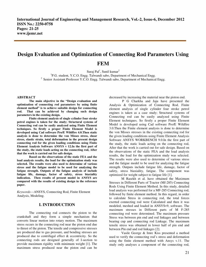
Table: 1. shows the result comparison for static
analysis
24
Following are Figures shows the optimized
results along with the results of figures in reference paper
and comparison for fatigue analysis of connecting rod at
load 4319N.
Above figure shows the comparison of safety factor at
4319N.
Above figure shows the comparison of biaxiality
indication at 4319N.
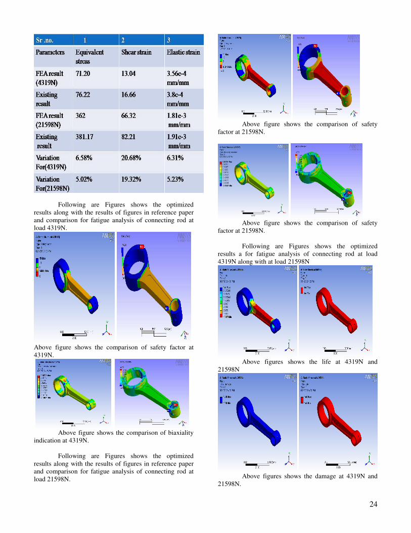
Following are Figures shows the optimized
results along with the results of figures in reference paper
and comparison for fatigue analysis of connecting rod at
load 21598N.
Above figure shows the comparison of safety
factor at 21598N.
Above figure shows the comparison of safety
factor at 21598N.
Following are Figures shows the optimized
results a for fatigue analysis of connecting rod at load
4319N along with at load 21598N
Above figures shows the life at 4319N and
21598N
Above figures shows the damage at 4319N and
21598N.

25
Table: 2. shows the result comparison for fatigue
analysis
Table 3: -Shows the comparison of Weight
Above table shows the weight optimization of
connecting rod, in existing model weight of connecting rod
was 131.5g. After optimization weight of connecting rod
is126.73, the percentage weight reduction is 3.62.
V. CONCLUSION
Finite Element analysis of the connecting rod of a Hero
Honda Splendor has been done using FEA tool ANSYS
Workbench. From the results obtained from FE analysis,
many discussions have been made. The results obtained
are well in agreement with the similar available existing
results. The model presented here, is well safe and under
permissible limit of stresses.
1. Conclusion is based on the current work that the
design parameter of connecting rod with
modification gives sufficient improvement in the
existing results.
2. The weight of the connecting rod is also reduced
by 0.477g. Thereby, reduces the inertia force.
3. Fatigue strength is the most important driving
factor for the design of connecting rod and it is
found that the fatigue results are in good
agreement with the existing result.
4. The stress is found maximum at the piston end so
the material is increased in the stressed portion to
reduce stress.
REFERENCES
[1] P. G. Charkha, S. B. Jaju (2009) “Analysis &
Optimization of Connecting Rod” Second International
Conference on Emerging Trends in Engineering and
Technology, ICETET-09.
[2] M. Rasekh, M. R. Asadi, A. Jafari, K. Kheiralipour
(2009) “Obtaining Maximum Stresses in Different Parts of
Tractor (Mf-285) Connecting Rods Using Finite Element
Method” Australian Journal of Basic and Applied
Sciences, Vol.3, pp 1438-1449.
[3] V. George, I. Kiss, (2010) “Computer aided design of
the connecting rod”.
[4] ANSYS WORKBENCH 12.0 Reference Manual.
[5] Pro/E Wildfire 4.0 Reference Manual
[6] Sharma. & Aggarwal “Book of machine design”.