design guide for hot dip best practice - gb...
TRANSCRIPT

Design Guide for Hot Dip Galvanizing –best practice for venting and draining
Servicing: Victoria, South Australia, NSW and Tasmania
Phone: (03) 8727 9300www.gbgal.com.au

2
Design Guide for Hot Dip Galvanizing – best practice for venting and draining
Contents
Introduction 3
Importance 4 of Venting and Draining• Purpose• Safety• Quality• Aesthetics
General 6 Principles • Hanging & Handling• Hole Position• Hole Size• Size & Weight• Distortion
Structural 13 Sections • Hollow Sections• Hot-rolled Sections
Frames and 19 Fabrications
Handrails/ 25 Balustrades
Hollow 28 Vessels
Overlapping 29 Surfaces
Moving 32 Parts
Threaded 33 Items
Appendices 34

3
Design Guide for Hot Dip Galvanizing – best practice for venting and draining
Introduction
It is important to consider the corrosion protection of ferrous articles when they are being designed. The key factors to consider when designing for hot dip galvanizing are the design’s impact on:
• Safety during the process• Quality of the coating• Aesthetics
This guide provides general information on basic design and detailing practice, including venting and draining, to assist in the safe and quality hot dip galvanizing of articles.

4
Design Guide for Hot Dip Galvanizing – best practice for venting and draining
PurposeFormation of the hot dip galvanized coating occurs from the reaction of ferrous metal and molten zinc. The ferrous metal needs to have a clean, unoxidised surface for the molten zinc to react with it.
The purpose of venting and draining is to ensure the article can be immersed and withdrawn from each stage in the process in a safe, efficient and effective manner. Both the pre-treatment solutions (to clean the article) and the molten zinc must be able to flow freely into and around the article so contact is made with all surfaces and all air is displaced. In turn, the liquids must then be able to flow out of and run off the article.
SafetyImmersion of a sealed article into molten zinc will result in any trapped moisture becoming super-heated steam inside the article and will lead to an explosion (Figure 1). Any trapped fluid from the pre-treatment will expand rapidly when dipped in molten zinc and is also a safety concern.
Trapped air due to an inadequately vented area of an article has two effects on galvanizing:1) Will stop the pre-treatment solutions from
cleaning that section of article and/or prevent zinc contacting the surface so the galvanized coating will not form, creating a bare spot.
2) Can cause the article to float in the zinc bath, due to the similar densities of molten zinc and steel. For hollow sections, a general rule is if an article contains more than 15% of its internal volume as air, it will not sink in the molten zinc.
Hence, vent holes need to be provided to allow air and moisture to escape.
The density and viscosity of molten zinc are also important factors in allowing adequate drainage of molten zinc from articles.
Figure 1: Purpose of Venting and Draining
Sealed UnitSuper heated stream inside leads to Explosions
One HoleWill vent steam but unit will float
Two HolesAllows unit to vent and drain and to be galvanized inside and out
Importance of Venting and Draining
5
Design Guide for Hot Dip Galvanizing – best practice for venting and draining
5
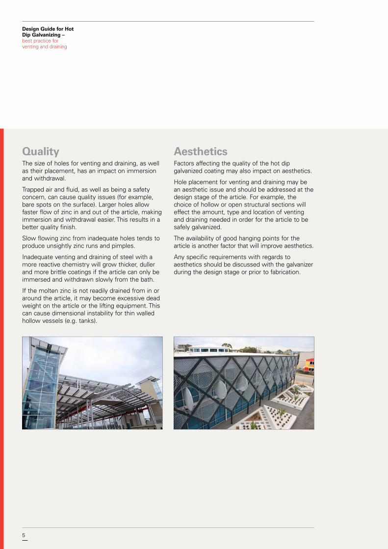
QualityThe size of holes for venting and draining, as well as their placement, has an impact on immersion and withdrawal.
Trapped air and fluid, as well as being a safety concern, can cause quality issues (for example, bare spots on the surface). Larger holes allow faster flow of zinc in and out of the article, making immersion and withdrawal easier. This results in a better quality finish.
Slow flowing zinc from inadequate holes tends to produce unsightly zinc runs and pimples.
Inadequate venting and draining of steel with a more reactive chemistry will grow thicker, duller and more brittle coatings if the article can only be immersed and withdrawn slowly from the bath.
If the molten zinc is not readily drained from in or around the article, it may become excessive dead weight on the article or the lifting equipment. This can cause dimensional instability for thin walled hollow vessels (e.g. tanks).
Aesthetics Factors affecting the quality of the hot dip galvanized coating may also impact on aesthetics.
Hole placement for venting and draining may be an aesthetic issue and should be addressed at the design stage of the article. For example, the choice of hollow or open structural sections will effect the amount, type and location of venting and draining needed in order for the article to be safely galvanized.
The availability of good hanging points for the article is another factor that will improve aesthetics.
Any specific requirements with regards to aesthetics should be discussed with the galvanizer during the design stage or prior to fabrication.
6
Design Guide for Hot Dip Galvanizing – best practice for venting and draining
Hanging and HandlingFacilities exist to galvanize components of virtually any size and shape, depending on handling equipment and layout of the galvanizing plant.
Most articles to be hot dip galvanized will be suspended from a jig and/or overhead crane using wires, chains, brackets or hooks while being processed.
The maximum size and weight that a particular galvanizer can process should always be checked at the design stage.
A directory listing the dimensions of all galvanizing baths operated by GAA members is available on the website: www.gaa.com.au
Adequate hanging points should be provided, e.g. suspension holes or lugs, taking into consideration article size and the lifting capacity of equipment.
For long, straight sections, 2 lifting lugs are preferred to avoid wire or chain marks.
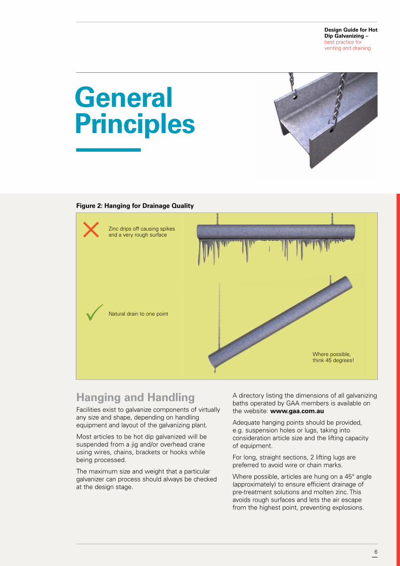
Where possible, articles are hung on a 45° angle (approximately) to ensure efficient drainage of pre-treatment solutions and molten zinc. This avoids rough surfaces and lets the air escape from the highest point, preventing explosions.
General Principles
Figure 2: Hanging for Drainage Quality
Where possible, think 45 degrees!
Natural drain to one point
Zinc drips off causing spikes and a very rough surface

7
Design Guide for Hot Dip Galvanizing – best practice for venting and draining
7
Long items will often be withdrawn from the bath at a shallow angle to avoid the lower submerged end from touching the bottom of the kettle. A shallow withdrawal angle causes the zinc to flow off at a slower rate leading to a heavier zinc layer on the top surface and greater quantities of ash trapped on the bottom surface of the steel article.
Small items such as fasteners, nuts and brackets may be placed into baskets rather than hung. See 'Centrifuging process' for more information.
Items longer or deeper than the bath size may be galvanized by using a double-dipping method. See 'Double dipping process' for more information. In these cases, material handling considerations will impact on cost. A better method may be to use bolted connections or modules for assembling post galvanizing.
Figure 3: Touch marks may not be avoidable with chains and wires

8 8
Design Guide for Hot Dip Galvanizing – best practice for venting and draining
Hole PositionThe location of the vent and drain holes shall be determined by the shape of the fabrication and the angle at which it is suspended for galvanizing, as well as the enclosed volume of zinc in the fabrication when draining. A good rule of thumb for the designer is to think of items being lowered into and lifted from the galvanizing bath at an approximate 45° angle as discussed in Figure 2.
• Holes should be placed as close to corners and/or connections as practical.
• Holes must be located as close to the high and low points of hollow sections as possible to prevent air locks, entrapment of pre-treatment chemicals and zinc puddling.
• Holes should be orientated in the same plane as the fabrication.
• Holes should not be located in the centre of end plates and connections.
• Holes should be diagonally opposed where possible.
Hole SizeDimensions of holes shall be determined by the trapped volume of air in the fabrication and the surface area of the steel in the vented area. Each square metre of steel surface produces approximately 200g of zinc ash, which must be able to escape through the holes.
• Minimum hole size is ø10mm• Hole diameters should be at least the same size
as the steel thickness.• Having bigger holes (where feasible) is always
better for the galvanizing outcome.
Refer to 'Hollow Sections' for applicable hole size charts.
Refer to 'Hollow Vessels' for applicable hole size chart.

9
Design Guide for Hot Dip Galvanizing – best practice for venting and draining
9
Size and Weighti. Centrifuge processSmall items are placed into a basket to be dipped and centrifuged. The size of baskets, centrifuges and other equipment will vary, just like general galvanizing baths.
Typically this process involves all the same stages as the general galvanizing process with the added centrifuging (or spinning) stage that occurs after withdrawal from the molten zinc. The centrifuging (or spinning) removes the excess zinc from the small articles, including from any threads or holes.
The coating thickness and mass requirements differ from other batch galvanized pieces due to the spinning process removing excess zinc.
Note: Not all galvanizers have centrifuge facilities and not all small items will be galvanized via the centrifuge process.

10 10
Design Guide for Hot Dip Galvanizing – best practice for venting and draining
ii. Double dipping processDouble dipping is a term used to describe the process of galvanizing an item which is longer, wider or deeper than the relevant available bath dimensions. In this procedure, the item is lowered into the bath so that half or more of its ‘over dimension’ is immersed in the molten zinc.
When the galvanized coating has been achieved on the immersed section, the item is withdrawn from the bath and adjusted in handling so that the ungalvanized portion can be immersed in the molten zinc.
In the double dipping procedure an overlap of zinc coating will occur and this will normally have to be addressed in the case of visually obvious structural elements, in particular any requirements for architecturally exposed structural steelwork should be identified prior to order. In addition, double dipping increases the possibility of distortion (dimensional instability) of fabricated items. Guidance in these cases should be sought from the galvanizer.

11
Design Guide for Hot Dip Galvanizing – best practice for venting and draining
11
Distortion (Dimensional Stability)
When steel sections or fabrications are immersed in molten zinc, their temperature is raised to that of the molten zinc, which is typically 450°C. The rate at which the steel reaches this temperature across its entire surface will depend on:
• the thickness of the individual sections making up the item,
• the total mass of the item,• the dimension of the item, and• speed of immersion.
At galvanizing temperatures, there is no change to structural steel's metallurgical microstructure and the process is not hot enough to have any heat treating effects on the mechanical properties of most structural steels after galvanizing.
However, at galvanizing temperatures, the yield strength of steel is temporarily lowered by approximately 50%. If any attached steel is not at the same temperature and any stresses exist, the weaker area will be subject to movement by the stronger area. There is a responsibility on the designer, the fabricator and the galvanizer to co-operate in ensuring distortion risks are minimised or eliminated.
Basic design rules for avoiding distortion1) Maximise the uniformity of heat transfer into
and out of the steel.a. Ensure venting and draining is adequate.
This will allow the article to be immersed in and withdrawn from the molten zinc as quickly as possible.
b. Minimise section thickness variations wherever possible in the fabrication.
2) Minimise the effect of stresses while the article is in the molten zinc.a. Use symmetrically rolled sections in
preference to angle or channel frames. I-beams are preferred to angles or channels.
b. Ensure assembly and welding techniques minimise stresses in components making up the article.i. If cutting plate to size, ensure all sides
are cut using the same technique. Guillotine is the preferred cutting technique.
ii. Bend members to the largest acceptable radii to minimize local stress concentration.
iii. Accurately pre-form members of an assembly so it is not necessary to force, spring or bend them into position during joining.
iv. Continuously weld joints using balanced welding techniques to reduce uneven thermal stresses.
v. Staggered welding techniques to produce a structural weld are acceptable.
vi. For staggered welding of material 4mm or less, weld centres should be closer than 100mm.

12 12
Design Guide for Hot Dip Galvanizing – best practice for venting and draining
3) Avoid designs that require double dipping. It is preferable to build assemblies and sub-assemblies in suitable modules allowing for quick immersion and galvanized in a single dip so the entire article can expand and contract uniformly.
4) Ensure the structural design of the item is sufficient to support its own weight at 50% of the steel's specified yield strength.
5) Avoid using large areas of thin (under 8mm), unbraced flat plate.
6) Use temporary bracing or reinforcing on thin-walled and asymmetrical designs.
Risk of distortion for various itemsLow risk: All hot rolled structural sections, fabrications containing angles, channels and universal hot rolled sections, tube and RHS sections and fabrications, ribbed or corrugated plate sections, grating, and heavy plate (over 16mm).
Medium risk: Light section roll formed products, long light walled conduit and tubing, fabrications containing asymmetrical weldments or steel of significantly different thickness, medium plate (8-16mm), and some double dipped items.
High risk: Thin sheet and plate (under 8mm depending on shape, area and bracing), floor-plate, deep plate web girders, platforms containing floor-plate, long channel sections with multiple weldments (cleats) on one side of web.
Figure 4: Thick + Thin = Distortion Figure 5: Avoid Distortion with Good Design
Thin sheet
Relatively uniform and symmetrical
designs
Heavy Angle
13
Design Guide for Hot Dip Galvanizing – best practice for venting and draining
Hollow SectionsBasic venting and draining rules for hollow sections
Size of holes• Holes shall be appropriately sized for the size
of the section to be galvanized. See Table 1 to Table 3 for the minimum recommendations for standard hollow sections.
• Vent holes shall be at least 10mm in diameter or the same thickness as the steel section.
• The length of the hollow section should also be taken into consideration for the required hole size. The hollow vessel rule (Table 4) may need to be applied for some longer lengths or larger volumes.
• Large hollow vessels require a vent and drain hole for every 0.5m3 of enclosed volume, each being a minimum of 50mm in diameter. See Table 4.
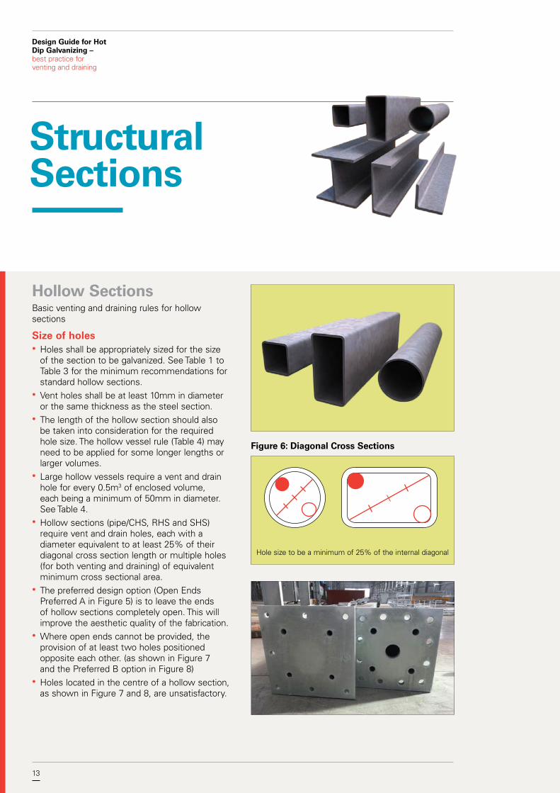
• Hollow sections (pipe/CHS, RHS and SHS) require vent and drain holes, each with a diameter equivalent to at least 25% of their diagonal cross section length or multiple holes (for both venting and draining) of equivalent minimum cross sectional area.
• The preferred design option (Open Ends Preferred A in Figure 5) is to leave the ends of hollow sections completely open. This will improve the aesthetic quality of the fabrication.
• Where open ends cannot be provided, the provision of at least two holes positioned opposite each other. (as shown in Figure 7 and the Preferred B option in Figure 8)
• Holes located in the centre of a hollow section, as shown in Figure 7 and 8, are unsatisfactory.
Figure 6: Diagonal Cross Sections
Structural Sections
Hole size to be a minimum of 25% of the internal diagonal

14 14
Design Guide for Hot Dip Galvanizing – best practice for venting and draining
Location of holes• Vent and drain holes shall be located as close as
possible to the high and low points of the hollow section when hung to prevent air locks, entrapment of pre-treatment solutions and zinc pooling as well as being oriented in the same plane as the fabrication (Figure 7).
• Holes must not be located in the centre of end plates and connections. This will cause cleaning fluids to be trapped and result in uncoated surfaces inside the plate or connection as well as potential 'blowouts' where the cleaning fluids are expelled from the hole under pressure creating bare spots on the finished article. On withdrawal from the galvanizing bath, centre located holes will trap zinc (Figure 7).
• Hollow sections connected together require external vent and drain holes as close to the connection as possible. Internal venting may also be used to ensure pre-treatment solutions and zinc can flow freely through the sections and steam generated from any liquids remaining inside the sections can be efficiently vented. For more information on internal venting, see 'Using Hollow Section'.
Figure 7: Hollow Section Ends - Inside View
Figure 8: End Plates for Hollow Sections
Open Ends Preferred A
• Base Plates• End Plates• Cap Plates• Seal Plates• Flanges
Properly Drained Preferred B Centre Hole Unsatisfactory
Zinc Trap
Opposite Drain Holes Preferred B Centre Hole UnsatisfactoryOpen Ends Preferred A

15
Design Guide for Hot Dip Galvanizing – best practice for venting and draining
15
Table 1: Standard Holes Sizes for CHS/Pipe
NB Outside Diameter
(mm)
1 Hole Ø (mm)
2 Holes Ø (mm)
4 Holes Ø (mm)
20 26.9 10 10 10
25 33.7 10 10 10
32 42.4 11 10 10
40 48.3 12 10 10
50 60.3 15 11 10
65 76.1 19 13 10
80 88.9 22 16 11
90 101.6 25 18 13
100 114.4 30 20 14
125 139.7 35 25 17
150 165.1 45 30 22
168.3 45 30 22
219.1 55 40 30
273.1 70 50 35
323.9 85 60 40
355.6 90 65 45
406.4 105 75 55
457 115 85 60
508 130 90 65
Table 2: Standard Holes Sizes for SHS
A x B (mm)
1 Hole Ø (mm)
2 Holes Ø (mm)
4 Holes Ø (mm)
20 x 20 10 10 10
25 x 25 10 10 10
30 x 30 11 10 10
35 x 35 12 10 10
40 x 40 14 10 10
50 x 50 18 13 10
65 x 65 25 16 11
75 x 75 25 19 13
89 x 89 35 22 16
90 x 90 35 25 16
100 x 100 35 25 18
125 x 125 45 35 22
150 x 150 55 40 30
200 x 200 75 50 35
250 x 250 90 65 45
300 x 300 110 75 55
350 x 350 125 90 65
400 x 400 145 100 75
A
B
Table 3: Standard Holes Sizes for RHS
A x B (mm)
1 Hole Ø (mm)
2 Holes Ø (mm)
4 Holes Ø (mm)
50 x 25 14 10 10
65 x 35 18 13 10
75 x 25 20 14 10
75 x 50 25 16 11
100 x 50 30 20 14
125 x 75 40 30 18
150 x 50 40 30 20
150 x 100 45 35 25
200 x 100 60 40 30
250 x 150 75 55 40
300 x 200 90 65 45
350 x 250 110 80 55
400 x 200 115 80 60
400 x 300 125 90 65
Note: ‘1 hole’, ‘2 holes’ and ‘4 holes’ means the number of holes in each otherwise unopen end.
A
B

16 16
Design Guide for Hot Dip Galvanizing – best practice for venting and draining
Hot Rolled Sections• End plates, gussets and stiffeners all restrict
drainage. Vent and drain holes or openings (e.g. snipes) need to be provided in the corners of connected structural member (Figure 9 and Figure 10).
• The corners of end plates, gussets and stiffeners can also be cropped (referred to in industry as ‘snipes’) to allow for venting and draining (Figure 9 and Figure 10).
• See the Snipe Guide (Figure 11) for the recommended snipe sizes for various structural members.
Figure 9: Hot Rolled Profiles – Typical Designs
End plates to be vented
Leave gaps between Cleats and Flanges
All Cleats, Gussets, Stiffeners to have corners sniped
Beams
Channels
Angles

17
Design Guide for Hot Dip Galvanizing – best practice for venting and draining
17
Figure 10: End Plate Options
Figure 11: Snipe Guide
Nominal Section
Snipe Size (mm)
PFC 150 to 250above 250
25x2530x30
Angle 100 to 150above 150
25x2530x30
UB up to 250above 250
25x2530x30
UC up to 200above 200
25x2530x30
(For the smaller sections, a hole is the more preferred option for venting.)
Option A – Holes in the end plate
Option B – Notches in web
B – B
A – A
4 x HOLES as close as possible to the corners
20mm diameter notches cut into web as close as possible to flanges
A
A
B
B
Figure 12: Snipe Gussets
25x25 Snipes

18 18
Design Guide for Hot Dip Galvanizing – best practice for venting and draining
Figure 13: Design Orientation Options
A Satisfactory B Satisfactory C Unsatisfactory

19
Design Guide for Hot Dip Galvanizing – best practice for venting and draining
Design details are important when fabricated articles are to be hot dip galvanized.
Figure 14 to Figure 24 show basic design practices to ensure articles are able to be successfully galvanized and a quality hot dip galvanized coating is achieved.
Some designs can provide adequate natural drainage without requiring holes (Figure 24).
Using Hollow SectionsExternal holes• External holes are needed to ensure quick
visual inspection and verification that work is safe to galvanize.
• Each member should have two holes in each end orientated in the plane of the fabrication.
• External holes are to be placed as close to the connection as possible.
• External holes size determined by 25% of the cross section. See 'Standard Hole Size Tables'.
Internal holes• Internal vent holes must be at least 50% of the
connecting section. It is recommended they be the same size as the internal diameter of the connecting section where practical. See Figures 14 and 18.
• Internal venting must be shown on shop detail drawings and be approved by the galvanizer prior to fabrication. This method of venting is also recommended to be approved by the structural engineer.
• Internal holes must be visible or be able to be otherwise proven to be satisfactorily formed for inspection purposes.
Frames and Fabrications
• A Ø10mm external check hole must be included at each location where internal venting is specified on the shop detail drawings. This best practice requirement will allow the galvanizer to safely proceed with dipping the article.
See 'Location of holes' and 'Size of holes' for more information.

20 20
Design Guide for Hot Dip Galvanizing – best practice for venting and draining
Figure 14: Closed Hollow Sections – Unsatisfactory
Completely sealed fabrications cannot be galvanized

21
Design Guide for Hot Dip Galvanizing – best practice for venting and draining
21
Figure 15: Mitred Joints – Preferred
Open Ends
External inspection check holes required (min Ø10mm)
Open Mitred Joints
Figure 16: External Venting Shop Detail – Preferred
Open ends where possible
External vent holes clearly shown
ONE REQ'D. MK 1001System GALV
Hole size = 25% of cross section
A A – A
A
600
50050 50
p100
2
p100
2
p100
2
p1004
p1003
m1001
1000
2-13Ø Hole (s) Thru
2-13Ø Hole (s) Thru
2-13Ø Hole (s)
Thru
1000
7050
500
MK
380
80
80
547
5070
380

22 22
Design Guide for Hot Dip Galvanizing – best practice for venting and draining
Figure 19: Internal Venting Shop Detail
Figure 17: Internal Vent Holes with No Inspection Holes – Non-Preferred
Figure 18: Internal Vent Holes – Drawing to clearly show items are "Internally Vented" with Inspection Holes - Preferred
Internal holes to be at least 50% of connecting section
External inspection check holes required (min Ø10mm)
Two holes covering at least half the covered surface area
Oxy blow hole same size as internal measurements of joining SHS/RHS/CHS
Internal Hole size to be at least 50% of connecting section
ONE REQ'D. MK 1002 System GALV
m1002
p1005
p100
6
p1005
MK
A
A
A – A
500
500
250
250
250
250
1-40Ø Hole (s)
1-40Ø Hole (s) thru
External inspection check holes required (min Ø10mm)
Inspection holes

23
Design Guide for Hot Dip Galvanizing – best practice for venting and draining
23
Using Other Structural Sections
Figure 20: Venting Hot Rolled Frames
All corners to be sniped to avoid zinc and air traps
Figure 21: Angle Connections Options
Stop angle short to avoid pockets
Snipe corner
or
Figure 22: Vented Frame
UB'sUC's PFC'sCleatsStiffeners
Show all corners with snipes
Basic guidance on design, venting and draining for fabricated frames or articles using structural sections are given in Figures 20 through 24.
The same design principles related to 'Hot Rolled Sections' should also be applied to the use of these sections in frames and general fabrications.

24 24
Design Guide for Hot Dip Galvanizing – best practice for venting and draining
Figure 24: Outward Facing Sections – Preferred
No special venting or draining provisions are required
Channels
Angles
Figure 23: Inward Facing Angles – Venting Required
Hole Positioned close to corner
Zinc Trap or Air Pocket
25
Design Guide for Hot Dip Galvanizing – best practice for venting and draining
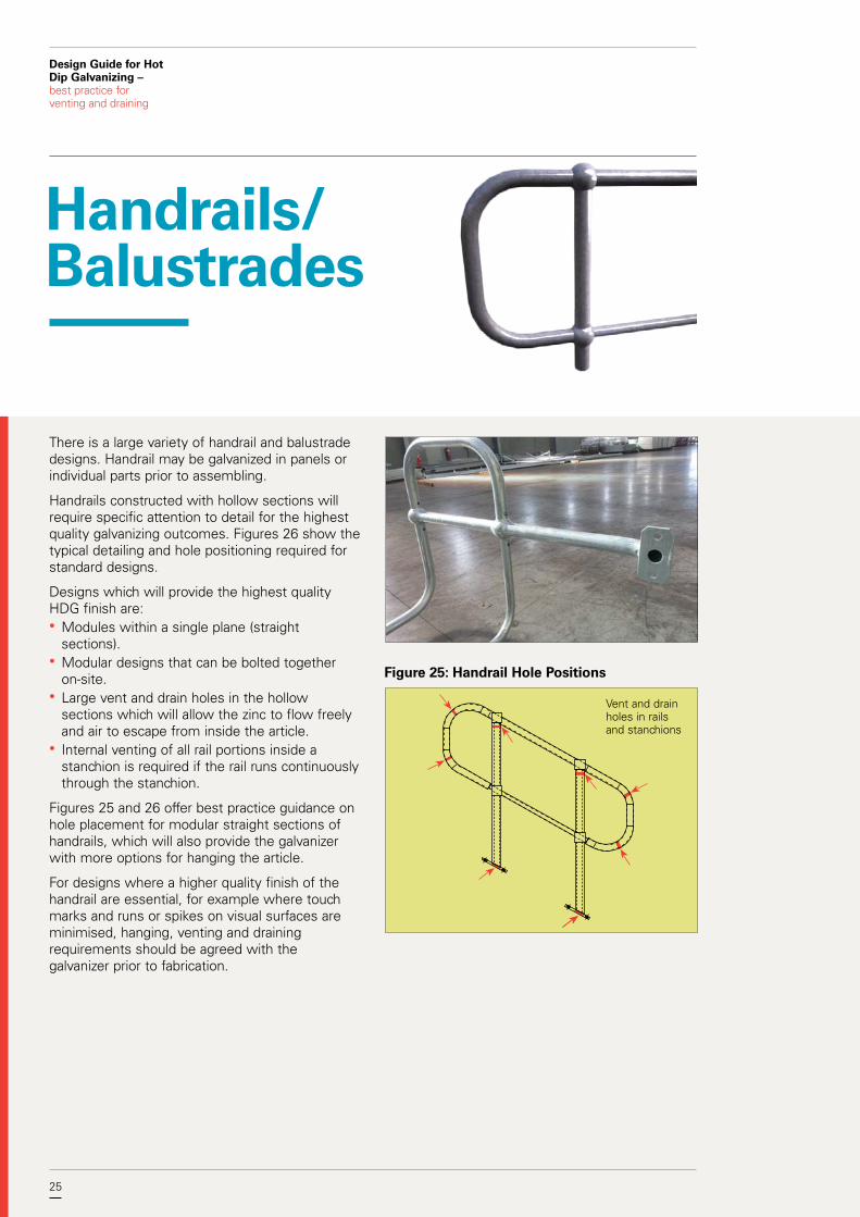
There is a large variety of handrail and balustrade designs. Handrail may be galvanized in panels or individual parts prior to assembling.
Handrails constructed with hollow sections will require specific attention to detail for the highest quality galvanizing outcomes. Figures 26 show the typical detailing and hole positioning required for standard designs.
Designs which will provide the highest quality HDG finish are:• Modules within a single plane (straight
sections).• Modular designs that can be bolted together
on-site.• Large vent and drain holes in the hollow
sections which will allow the zinc to flow freely and air to escape from inside the article.
• Internal venting of all rail portions inside a stanchion is required if the rail runs continuously through the stanchion.
Figures 25 and 26 offer best practice guidance on hole placement for modular straight sections of handrails, which will also provide the galvanizer with more options for hanging the article.
For designs where a higher quality finish of the handrail are essential, for example where touch marks and runs or spikes on visual surfaces are minimised, hanging, venting and draining requirements should be agreed with the galvanizer prior to fabrication.
Handrails/ Balustrades
Figure 25: Handrail Hole Positions
Vent and drain holes in rails and stanchions

26 26
Design Guide for Hot Dip Galvanizing – best practice for venting and draining
Figure 26: Handrail Detail
Open ends stanchion
Open ends are best
Ø 12mm galv holes
ONE REQ'D. MK HR 1001System GALV
A – A A
A
1200
600300 300
1-12Ø Hole (s)1-12Ø Hole (s)1-12Ø Hole (s)
1-12Ø Hole (s)
2-18Ø Hole (s) 4.6S
2-18Ø Hole (s) 4.6S
SMid rail
S
S
HCB
457
5129
5151 51
MK
635
Designs which will need special consideration to provide the highest quality HDG finish are:• Handrails with multiple planes (corner or bent
sections) so that some parts of the handrail vent and drain slower than others parts within the same handrail. This can affect available hanging angles due to both vent and drain designs and bath size restrictions which could reduce coating quality.
• Vent and drain holes that are internal will need to be verified through the use of external inspection holes.

27
Design Guide for Hot Dip Galvanizing – best practice for venting and draining
27
Opposite Drain Holes Preferred B
Centre Hole Unsatisfactory
Open Ends Preferred A
Figure 27: Stanchion Base Plates

28
Design Guide for Hot Dip Galvanizing – best practice for venting and draining
• Hollow vessels may require temporary stays during the galvanizing process to prevent distortion
• Hollow vessels should have at least 1 vent hole and 1 drain hole
• Standard minimum venting and draining for an enclosed volume is a 50mm diameter hole for each 0.5m3 (see Table 4)
• Openings should finish flush inside the vessel • Baffles inside vessels should have openings to
allow free flow of liquid throughout. A minimum of 75mm snipes is required. See Figures 8 to 11 for more information on snipes.
Table 4: Minimum hole sizes for hollow vessels
Section Volume (litres)
1 Hole Ø (mm)
2 Holes Ø (mm)
4 Holes Ø (mm)
500 50 35 25
1000 70 50 35
1500 90 65 45
2000 100 70 50
2500 115 80 55
3000 125 90 65
3500 135 95 70
4000 145 100 70
4500 150 110 75
5000 160 115 80
5500 165 120 85
6000 175 125 90
6500 180 130 90
7000 190 135 95
7500 195 140 100
8000 200 145 100
8500 210 145 105
9000 215 150 110
9500 220 155 110
10000 225 160 115
Hollow Vessels
Figure 28: Hollow Vessels - Good Design
Vent / Drain Holes at least 50mm for each 0.5 cubic metre
Internal Baffles Cropped
Figure 29: Hollow Vessels - Bad Design
Vent pipe Flanges should finish flush inside
Fluid / Air pocket
29
Design Guide for Hot Dip Galvanizing – best practice for venting and draining
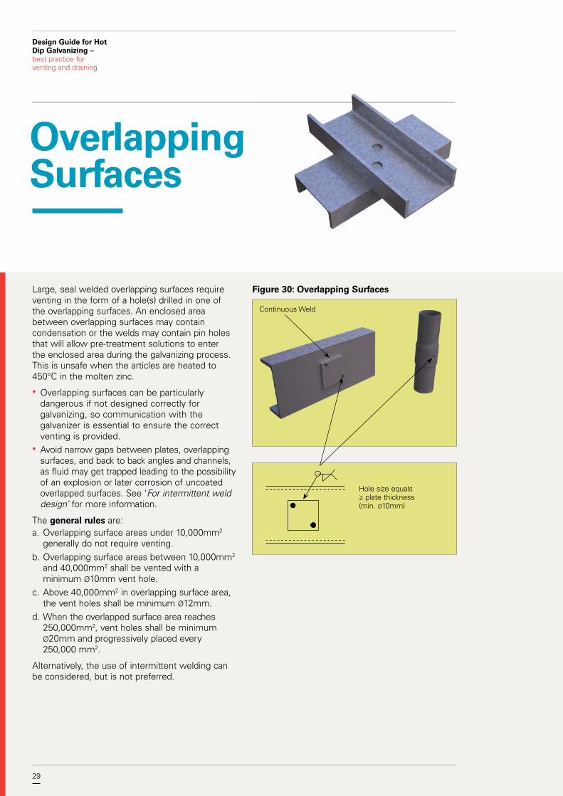
Large, seal welded overlapping surfaces require venting in the form of a hole(s) drilled in one of the overlapping surfaces. An enclosed area between overlapping surfaces may contain condensation or the welds may contain pin holes that will allow pre-treatment solutions to enter the enclosed area during the galvanizing process. This is unsafe when the articles are heated to 450°C in the molten zinc.
• Overlapping surfaces can be particularly dangerous if not designed correctly for galvanizing, so communication with the galvanizer is essential to ensure the correct venting is provided.
• Avoid narrow gaps between plates, overlapping surfaces, and back to back angles and channels, as fluid may get trapped leading to the possibility of an explosion or later corrosion of uncoated overlapped surfaces. See ‘For intermittent weld design’ for more information.
The general rules are:a. Overlapping surface areas under 10,000mm2
generally do not require venting.b. Overlapping surface areas between 10,000mm2
and 40,000mm2 shall be vented with a minimum Ø10mm vent hole.
c. Above 40,000mm2 in overlapping surface area, the vent holes shall be minimum Ø12mm.
d. When the overlapped surface area reaches 250,000mm2, vent holes shall be minimum Ø20mm and progressively placed every 250,000 mm2.
Alternatively, the use of intermittent welding can be considered, but is not preferred.
Overlapping Surfaces
Figure 30: Overlapping Surfaces
Continuous Weld
Hole size equals ≥ plate thickness (min. Ø10mm)

30 30
Design Guide for Hot Dip Galvanizing – best practice for venting and draining
• Longer or larger overlapping areas require spaced holes for progressive venting. Very large overlapping areas should be avoided as they are an undesirable design for galvanizing and are areas of high risk for crevice corrosion.
• The same principles used for general venting and draining should be used for location of vent holes in overlapping areas, i.e. in corners and diagonally opposite.
• There should be a flush fit-up of the items.• Putting the hole through both sections can
also be helpful.
When overlaps are unavoidable:• Seal edges using pinhole-free continuous welding
and provide 2 vent holes for best outcomes.• Pinholes from welding are very dangerous in
articles to be galvanized and must be avoided.• Size of the hole(s) should be equal to or greater
than the steel thickness, with the minimum being 10mm.
• Avoid gaps between members or have at least a 2.5mm gap and stitch weld so all the surfaces can be galvanized. In this case, additional vent holes would not be required (see ‘For intermittent weld design’).
• Intermediate sized overlaps should be judged on the basis of weld integrity and residual welding heat in the joint to ensure total dryness at time of sealing.
Figure 31: Overlapping Sections
Holes in one member only
Figure 32: Large Overlapping Areas
Progressive Vent Holes required. Hole size to be equal or greater than steel thickness, with a minimum Ø10mm
Example: Crane Beams

31
Design Guide for Hot Dip Galvanizing – best practice for venting and draining
31
For intermittent weld designsThe minimum space between the surfaces of the two components shall be at least 2.5mm.
This ensures:a. The overlapped area is self-venting.b. Avoids pre-treatment solutions being trapped in
the gaps during the galvanizing process and seeping out over time.
c. Allows all surfaces to be galvanized.
Figure 33: Overlapping Areas - Venting Unsatisfactory
Gap too small

32
Design Guide for Hot Dip Galvanizing – best practice for venting and draining
Moving Parts
Where articles require free movement of parts, e.g. drop handles, hinges, shackles, shafts or spindles:• A radial clearance should be applied to the part
to allow for the galvanized coating thickness. Recommended minimum radial clearances are shown in Table 5.
• Parts need to be disassembled and galvanized separately.
Table 5: Recommended minimum radial clearance before galvanizing
Shaft or spindle size (mm)
Minimum radial clearance (mm)
< Ø10 1.0
≥ Ø10 to ≤ Ø30 2.0
> Ø30 2.5
Note: Some fettling may be required after galvanizing to enable parts to be free moving.
Figure 34: Moving Parts – Swinging Gate
Radial Clearance

33
Design Guide for Hot Dip Galvanizing – best practice for venting and draining
Due to their small relative size, threaded fasteners, nuts and washers are usually hot dip galvanized via the centrifuge process. Like other moving parts, each part needs to be galvanized separately.
• The HDG process develops a coating of a minimum average thickness of 50µm on threads, as defined in AS/NZS 1214. Hence, it is necessary to form bolt threads to special limits to accommodate the coating.
• There are two different methods of manufacture which take into account the necessary clearances for the HDG coating applied to fasteners.
• The usual method consists of using nuts tapped oversize to tolerance class 6AZ or 6AX after coating, to mate with bolts manufactured with threads to tolerance position g or h before coating. AS/NZS 1214 provides detailed information on tolerances for bolt manufacturers and marking requirements.
The galvanized coating on the thread of the stud or bolt will provide corrosion protection for the internal thread of the nut.
Threaded Items
Increase Tolerance
Figure 35: Internal Threads

34
Design Guide for Hot Dip Galvanizing – best practice for venting and draining
Appendices
Appendix A – Suitable Materials• Most ferrous materials are suitable to be hot dip
galvanized, including sound stress-free castings.• Non-ferrous materials such as brass, aluminium
and copper are not suited to the hot dip galvanizing process.
• It is not recommended to galvanize stainless steels.
• Most hot rolled or cold formed steels, including structural angles, UB’s, UC’s, welded beams, channels, welded CHS, RHS & SHS, reinforcement steels and fastener grade steels can be galvanized. In general, the mechanical properties of structural steels are not affected by the galvanizing process.
• High strength steel up to 340HV are also able to be galvanized when acid pickling is not used in the pre-treatment of the steel.
• Steel composition (particularly silicon and phosphorus content) can affect the characteristics of the hot dip galvanized coating.
• Sulphur-containing free-cutting steels (for example S1214) are normally unsuitable for hot dip galvanizing.
• Grey cast iron and malleable cast iron can be galvanized, but special considerations need to be met. For more information, refer to Clauses 2 and 9 of AS/NZS 2312.2.
• Combinations of ferrous materials or surface conditions• Fabrications containing a combination of
castings and steels, or rusted and mill scaled surfaces may be abrasive blast cleaned before galvanizing to provide a more consistent initial surface finish.
• Weld slags must be removed, which can be done via chipping, grinding, or using a pneumatic needle gun.
• Brazed assemblies may be galvanized, but check first with your galvanizer.
• Soft soldered assemblies cannot be galvanized.
35
Design Guide for Hot Dip Galvanizing – best practice for venting and draining
35
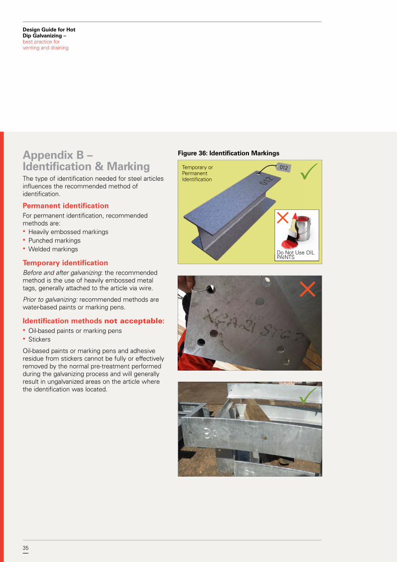
Appendix B – Identification & MarkingThe type of identification needed for steel articles influences the recommended method of identification.
Permanent identificationFor permanent identification, recommended methods are:• Heavily embossed markings• Punched markings• Welded markings
Temporary identification Before and after galvanizing: the recommended method is the use of heavily embossed metal tags, generally attached to the article via wire.
Prior to galvanizing: recommended methods are water-based paints or marking pens.
Identification methods not acceptable:• Oil-based paints or marking pens• Stickers
Oil-based paints or marking pens and adhesive residue from stickers cannot be fully or effectively removed by the normal pre-treatment performed during the galvanizing process and will generally result in ungalvanized areas on the article where the identification was located.
Temporary or Permanent Identification
Do Not Use OIL PAINTS
Figure 36: Identification Markings
012

We provide information, publications and assistance on all aspects of design, performance and applications of hot dip galvanizing.
Level 5 124 Exhibition Street Melbourne Victoria 3000
Telephone 03 9654 1266 Email [email protected] Web gaa.com.au
GAA website