design manual tabulating guardrail - iowa … · page 1 of 9 . tabulating guardrail can be...
TRANSCRIPT
Page 1 of 9
Tabulating guardrail can be confusing because the tabulations are set up to handle many different situations. Because of this, some columns are used in some situations but not used in other situations. Tabulating guardrail consistently makes it easier for contractors and inspectors to understand the designer’s intent and helps ensure that the guardrail is installed correctly.
The examples on the following pages illustrate how to tabulate guardrail for some common situations.
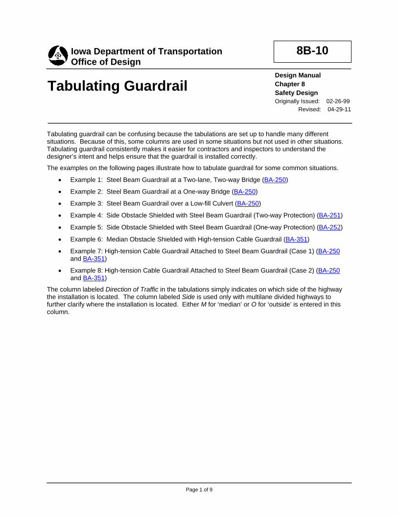
• Example 1: Steel Beam Guardrail at a Two-lane, Two-way Bridge (BA-250)
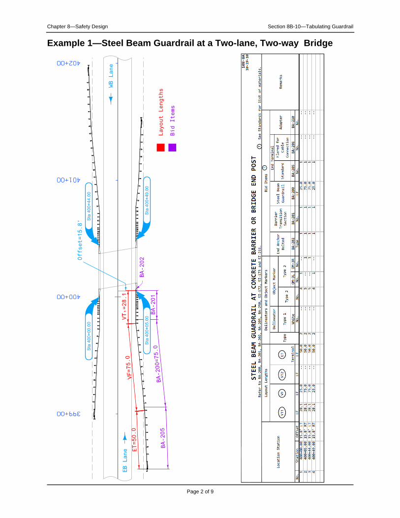
• Example 2: Steel Beam Guardrail at a One-way Bridge (BA-250)
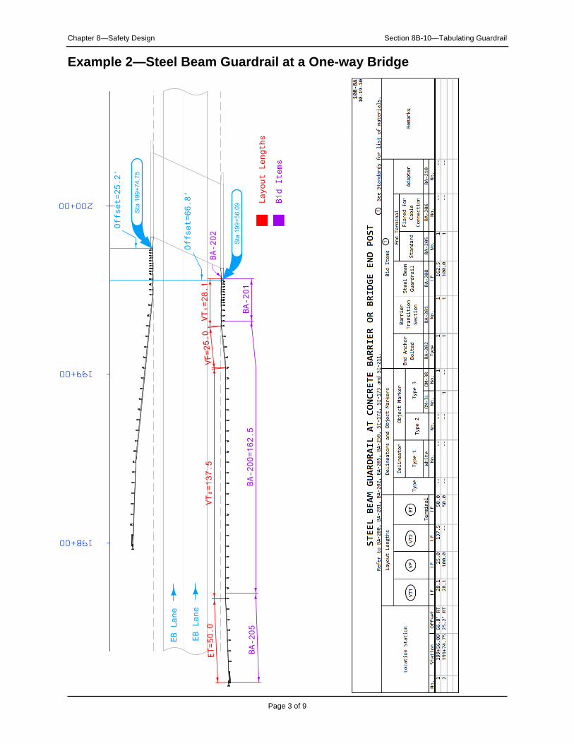
• Example 3: Steel Beam Guardrail over a Low-fill Culvert (BA-250)
• Example 4: Side Obstacle Shielded with Steel Beam Guardrail (Two-way Protection) (BA-251)
• Example 5: Side Obstacle Shielded with Steel Beam Guardrail (One-way Protection) (BA-252)
• Example 6: Median Obstacle Shielded with High-tension Cable Guardrail (BA-351)
• Example 7: High-tension Cable Guardrail Attached to Steel Beam Guardrail (Case 1) (BA-250 and BA-351)
• Example 8: High-tension Cable Guardrail Attached to Steel Beam Guardrail (Case 2) (BA-250 and BA-351)
The column labeled Direction of Traffic in the tabulations simply indicates on which side of the highway the installation is located. The column labeled Side is used only with multilane divided highways to further clarify where the installation is located. Either M for ‘median’ or O for ‘outside’ is entered in this column.
Tabulating Guardrail
8B-10
Design Manual Chapter 8 Safety Design Originally Issued: 02-26-99
Revised: 04-29-11
Iowa Department of Transportation Office of Design
399+00
400+00
401+00
402+00
VT
1=
28
.1
WB
Lane
EB
Lan
e
Bid
Ite
ms
Lay
ou
t L
en
gth
s
BA
-202
BA-205
BA-200=75.0
VF=75.0
ET=50.0
Offset=
15
.8’
BA
-201
Sta
40
0+
00
.00
Sta
40
0+
05
.00
Sta
40
0+
49
.00
Sta
40
0+
44
.00
Chapter 8—Safety Design Section 8B-10—Tabulating Guardrail
Page 2 of 9
Example 1—Steel Beam Guardrail at a Two-lane, Two-way Bridge
VT
1=
28
.1VF=25.0
BA
-202
ET=50.0
EB
Lan
e
EB
Lan
e
Bid
Ite
ms
Lay
ou
t L
en
gth
s
VT
2=
137.5
198+00
199+00
200+00
Offset=
66
.8’
Offset=
25
.2’
BA
-201
BA
-205
BA
-2
00
=1
62
.5
Sta
19
9+
56
.09
Sta
19
9+
74
.75
Chapter 8—Safety Design Section 8B-10—Tabulating Guardrail
Page 3 of 9
Example 2—Steel Beam Guardrail at a One-way Bridge
Bid
Ite
ms
Lay
ou
t L
en
gth
s
D0=
12.0
’
Offset=
24
.0’
EB
Lan
e
WB
Lane
VT
1 =
43.8
AET=50.0
VT
1 =
25.0
TET=50.0
10+00
9+00
11+00
BA
-210 B
A-200=
62.5
BA-205
BA-205
Sta
10+
18.8
0
Sta
9+
81.2
1
Chapter 8—Safety Design Section 8B-10—Tabulating Guardrail
Page 4 of 9
Example 3—Steel Beam Guardrail over a Low-fill Culvert
Bid
Ite
ms
Lay
ou
t L
en
gth
s
WB
Lane
EB
Lan
e
VT
1 =
25.0
Obsta
cle
T
D0=
10.0
’
Offset=
22
.0’
AV
T1 =
18.8
ET=50.0
VF =25.0
AET=50.0
1319+00
1320+00
1321+00
BA
-200=
62.5
BA-205
BA-205
Sta
13
20
+0
0.0
0
Chapter 8—Safety Design Section 8B-10—Tabulating Guardrail
Page 5 of 9
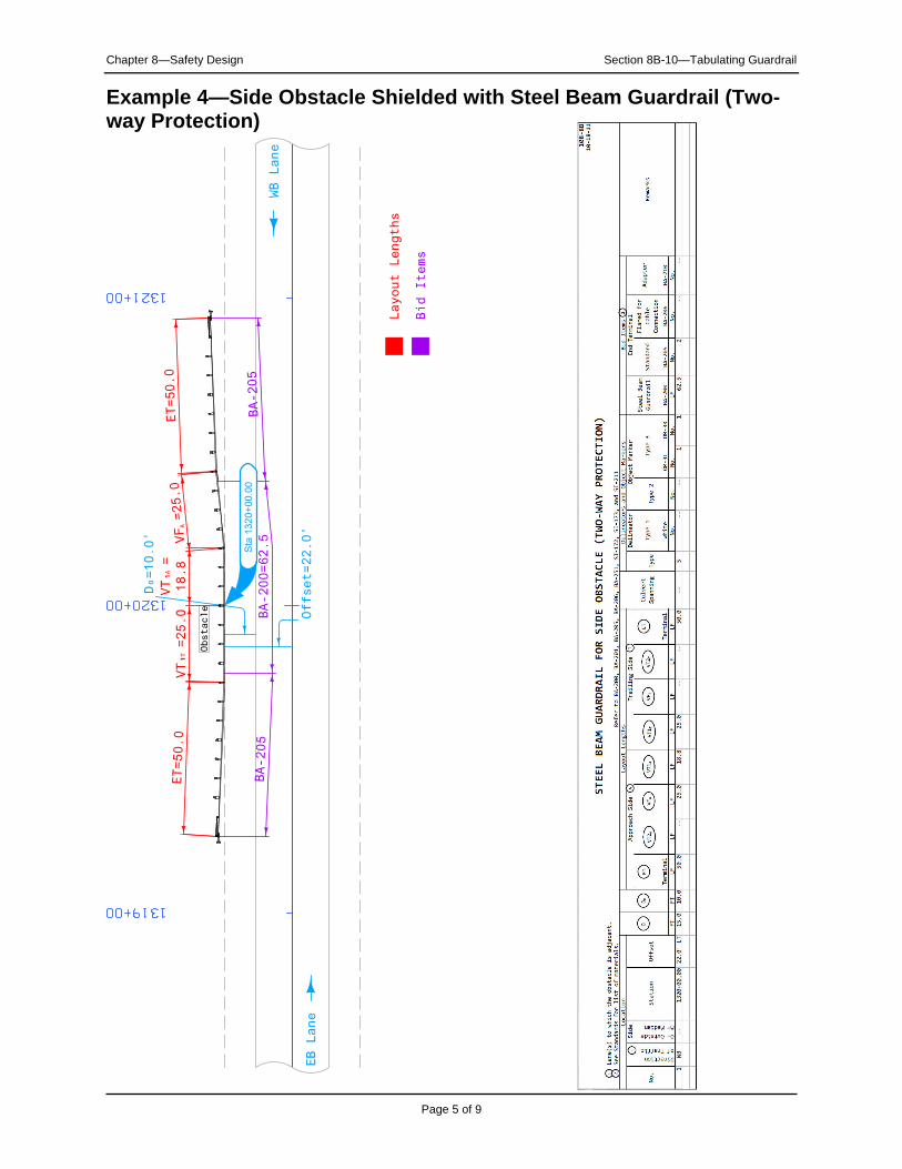
Example 4—Side Obstacle Shielded with Steel Beam Guardrail (Two-way Protection)

399+00
400+00
401+00
Bid
Ite
ms
Lay
ou
t L
en
gth
s
EB
Lan
e
EB
Lan
e
Offset=
77
.0’
VT
1 =
12.5
T
EA
=9.4 D0=
10.0
’
18.8
VT
1 =
A
12.5
VT
2 =
A
ET=50.0
VF =25.0
A
BA
-203
BA-200=62.5
BA-205
Sta
40
0+
00
.00
Chapter 8—Safety Design Section 8B-10—Tabulating Guardrail
Page 6 of 9
Example 5—Side Obstacle Shielded with Steel Beam Guardrail (One-way Protection)
EB
Lan
e
EB
Lan
e
WB
Lane
WB
Lane
Bid
Ite
ms
C =
139.1
C0
=4
0.0
Prote
cti
on L
ength
=179.1
A
D0=
20.5
’
199+00
198+00
200+00
201+00
Dim
en
sio
ns
Bridge P
iers
End A
nchor
End A
nchor
(L
ength
Varie
s)
(L
ength
Varie
s)
Sta
20
1+
59
.10
Sta
19
8+
40
.90
Chapter 8—Safety Design Section 8B-10—Tabulating Guardrail
Page 7 of 9
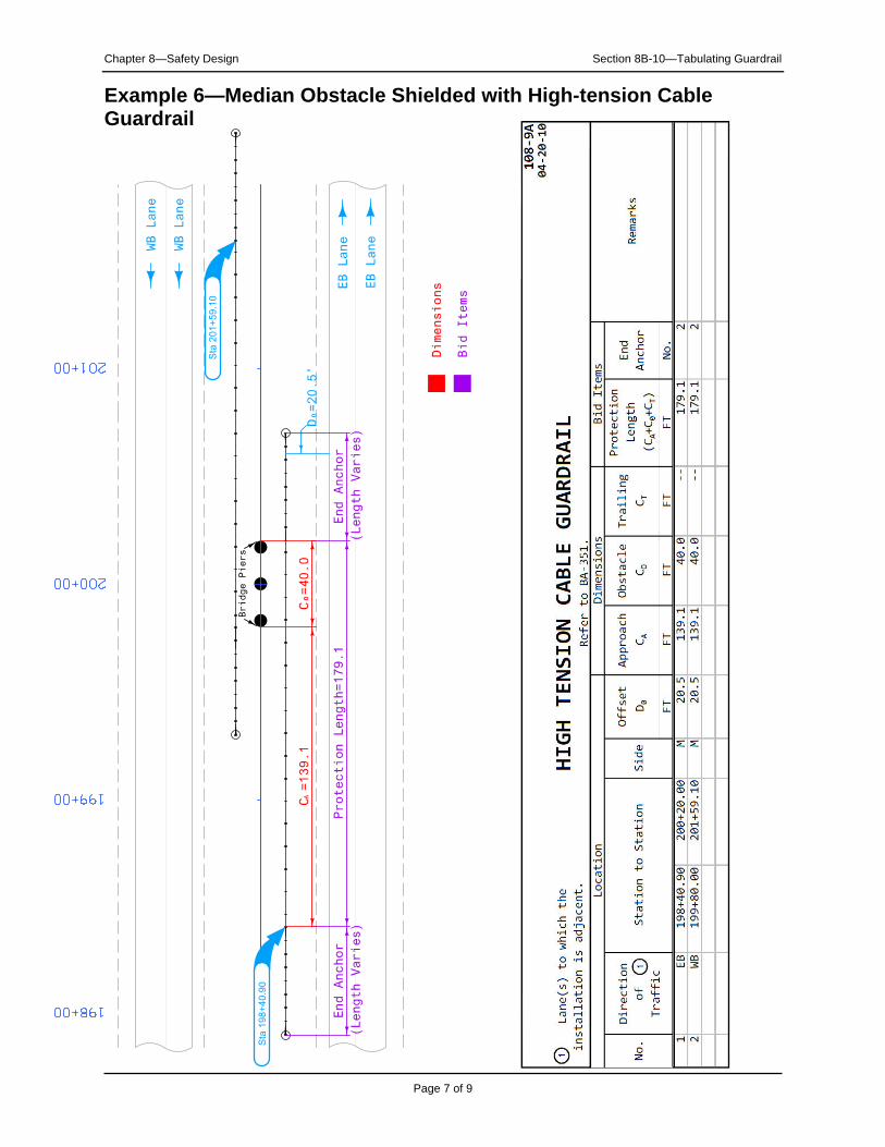
Example 6—Median Obstacle Shielded with High-tension Cable Guardrail
Layout
Length
s &
Dim
ensio
ns
Bid
Ite
ms
498+00
499+00
500+00
BA
-202
Offset=
22
.0’
VT
1=
53
.1ET=37.5
D0=
10.0
’
C =
500.0
A
Anchor S
ecti
on
Sp
ecial
Protection Length=500.0
D0
=1
2.0
EB
Lan
e
WB
Lane
50.0
’
50.0
’50:1 Taper =100.0’
BA
-201
BA-206
BA
-2
00
=2
5.0
Sta
50
0+
00
.00
Sta
49
9+
90
.87
Sta
50
0+
45
.87
Sta
50
0+
55
.00
501+00
Chapter 8—Safety Design Section 8B-10—Tabulating Guardrail
Page 8 of 9
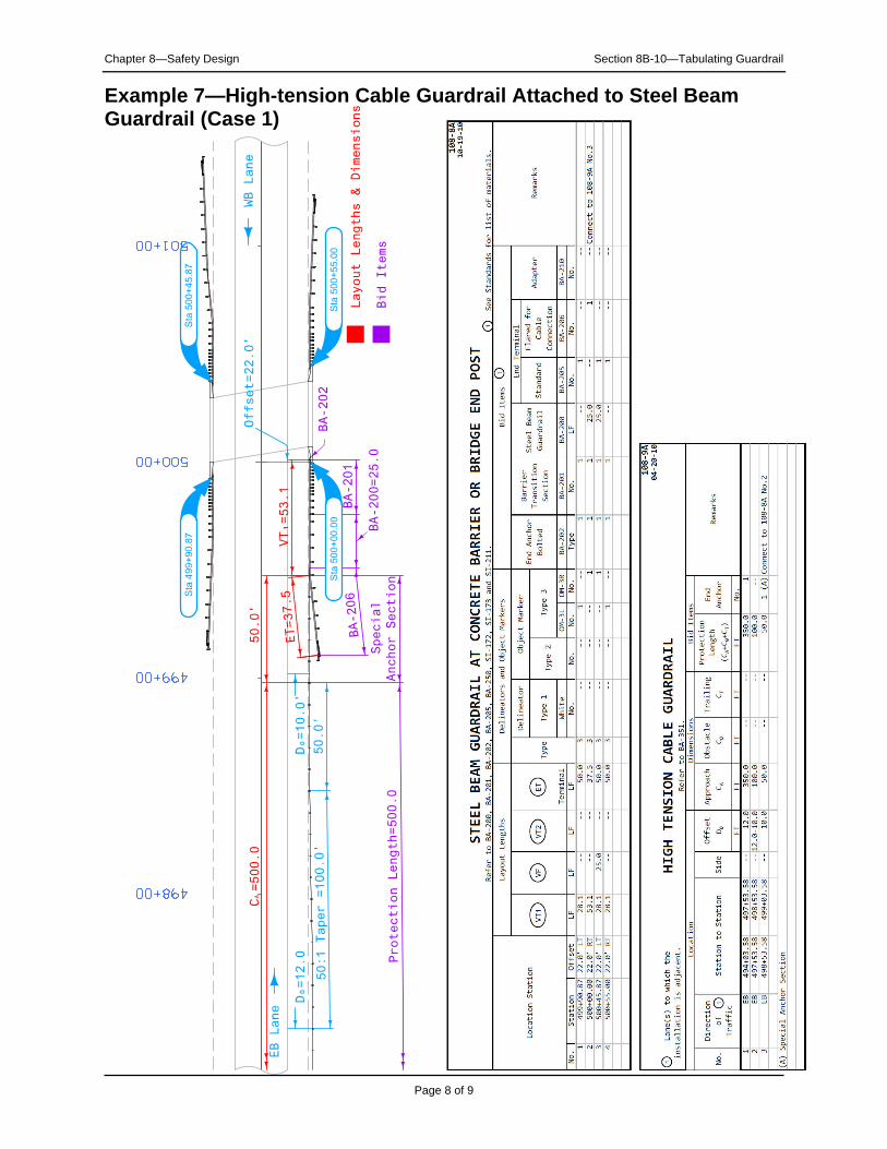
Example 7—High-tension Cable Guardrail Attached to Steel Beam Guardrail (Case 1)
198+00
199+00
200+00
BA
-202
VT
1=
28
.1
Anchor S
ecti
on
Sp
ecial
Prote
cti
on L
ength
=800.0
D0=
11.0
’
C =
800.0
A
ET=37.5
VT
2=
25
.0VF=50.0
EB
Lan
e
EB
Lan
e
Offset=
25
.2’
Offset=
66
.8’
Bid
Ite
ms
Layout
Length
s &
Dim
ensio
ns
50
.0’
BA
-201
BA-200=75.0
BA-206
Sta
19
9+
56
.09
Sta
19
9+
74
.75
Sta
19
8+
23
.26
Chapter 8—Safety Design Section 8B-10—Tabulating Guardrail
Page 9 of 9
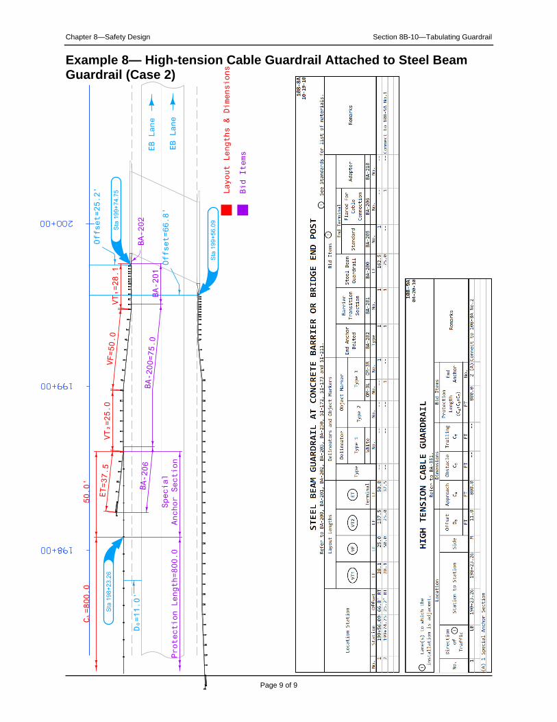
Example 8— High-tension Cable Guardrail Attached to Steel Beam Guardrail (Case 2)

Chronology of Changes to Design Manual Section:
008B-010 Tabulating Guardrail4/29/2011 Revised
Updated examples for the BA series and added examples with high-tension cable guardrail.
6/18/2004
Previously Updated.