design of a novel variable stiffness gripper using ...ahajiagh/papers/main-final_6pages... ·...
TRANSCRIPT
Design of a Novel Variable Stiffness Gripper Using Permanent Magnets
Amirhossein H. Memar, Nicholas Mastronarde and Ehsan T. Esfahani
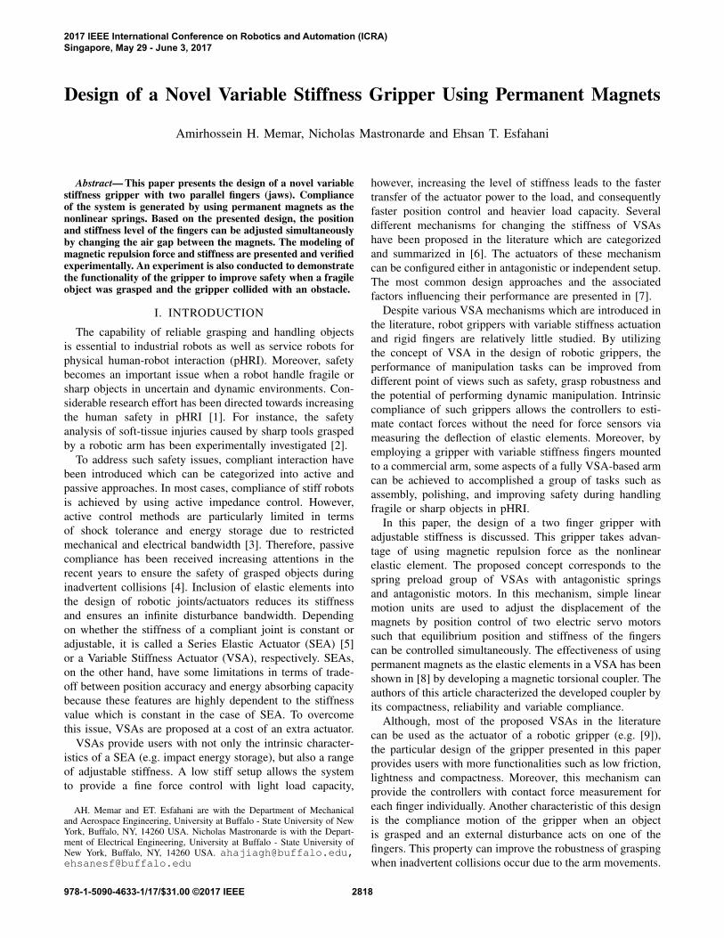
Abstract— This paper presents the design of a novel variablestiffness gripper with two parallel fingers (jaws). Complianceof the system is generated by using permanent magnets as thenonlinear springs. Based on the presented design, the positionand stiffness level of the fingers can be adjusted simultaneouslyby changing the air gap between the magnets. The modeling ofmagnetic repulsion force and stiffness are presented and verifiedexperimentally. An experiment is also conducted to demonstratethe functionality of the gripper to improve safety when a fragileobject was grasped and the gripper collided with an obstacle.
I. INTRODUCTION
The capability of reliable grasping and handling objects
is essential to industrial robots as well as service robots for
physical human-robot interaction (pHRI). Moreover, safety
becomes an important issue when a robot handle fragile or
sharp objects in uncertain and dynamic environments. Con-
siderable research effort has been directed towards increasing
the human safety in pHRI [1]. For instance, the safety
analysis of soft-tissue injuries caused by sharp tools grasped
by a robotic arm has been experimentally investigated [2].
To address such safety issues, compliant interaction have
been introduced which can be categorized into active and
passive approaches. In most cases, compliance of stiff robots
is achieved by using active impedance control. However,
active control methods are particularly limited in terms
of shock tolerance and energy storage due to restricted
mechanical and electrical bandwidth [3]. Therefore, passive
compliance has been received increasing attentions in the
recent years to ensure the safety of grasped objects during
inadvertent collisions [4]. Inclusion of elastic elements into
the design of robotic joints/actuators reduces its stiffness
and ensures an infinite disturbance bandwidth. Depending
on whether the stiffness of a compliant joint is constant or
adjustable, it is called a Series Elastic Actuator (SEA) [5]
or a Variable Stiffness Actuator (VSA), respectively. SEAs,
on the other hand, have some limitations in terms of trade-
off between position accuracy and energy absorbing capacity
because these features are highly dependent to the stiffness
value which is constant in the case of SEA. To overcome
this issue, VSAs are proposed at a cost of an extra actuator.
VSAs provide users with not only the intrinsic character-
istics of a SEA (e.g. impact energy storage), but also a range
of adjustable stiffness. A low stiff setup allows the system
to provide a fine force control with light load capacity,
AH. Memar and ET. Esfahani are with the Department of Mechanicaland Aerospace Engineering, University at Buffalo - State University of NewYork, Buffalo, NY, 14260 USA. Nicholas Mastronarde is with the Depart-ment of Electrical Engineering, University at Buffalo - State University ofNew York, Buffalo, NY, 14260 USA. [email protected],[email protected]
however, increasing the level of stiffness leads to the faster
transfer of the actuator power to the load, and consequently
faster position control and heavier load capacity. Several
different mechanisms for changing the stiffness of VSAs
have been proposed in the literature which are categorized
and summarized in [6]. The actuators of these mechanism
can be configured either in antagonistic or independent setup.
The most common design approaches and the associated
factors influencing their performance are presented in [7].
Despite various VSA mechanisms which are introduced in
the literature, robot grippers with variable stiffness actuation
and rigid fingers are relatively little studied. By utilizing
the concept of VSA in the design of robotic grippers, the
performance of manipulation tasks can be improved from
different point of views such as safety, grasp robustness and
the potential of performing dynamic manipulation. Intrinsic
compliance of such grippers allows the controllers to esti-
mate contact forces without the need for force sensors via
measuring the deflection of elastic elements. Moreover, by
employing a gripper with variable stiffness fingers mounted
to a commercial arm, some aspects of a fully VSA-based arm
can be achieved to accomplished a group of tasks such as
assembly, polishing, and improving safety during handling
fragile or sharp objects in pHRI.
In this paper, the design of a two finger gripper with
adjustable stiffness is discussed. This gripper takes advan-
tage of using magnetic repulsion force as the nonlinear
elastic element. The proposed concept corresponds to the
spring preload group of VSAs with antagonistic springs
and antagonistic motors. In this mechanism, simple linear
motion units are used to adjust the displacement of the
magnets by position control of two electric servo motors
such that equilibrium position and stiffness of the fingers
can be controlled simultaneously. The effectiveness of using
permanent magnets as the elastic elements in a VSA has been
shown in [8] by developing a magnetic torsional coupler. The
authors of this article characterized the developed coupler by
its compactness, reliability and variable compliance.
Although, most of the proposed VSAs in the literature
can be used as the actuator of a robotic gripper (e.g. [9]),
the particular design of the gripper presented in this paper
provides users with more functionalities such as low friction,
lightness and compactness. Moreover, this mechanism can
provide the controllers with contact force measurement for
each finger individually. Another characteristic of this design
is the compliance motion of the gripper when an object
is grasped and an external disturbance acts on one of the
fingers. This property can improve the robustness of grasping
when inadvertent collisions occur due to the arm movements.
2017 IEEE International Conference on Robotics and Automation (ICRA)Singapore, May 29 - June 3, 2017
978-1-5090-4633-1/17/$31.00 ©2017 IEEE 2818

II. DESIGN
A. Concept
The main objectives for the design of the gripper was
simultaneous stiffness and position control of the parallel
jaws using two identical actuators connected to compliant
elements. In addition, due to the need for attaching the
gripper to the end-effector of a lightweight robotic arm, there
was a limitation in terms of size and weight of the gripper.
One of the key features required for generating stiffness
variation with preload springs in an antagonistic mechanism
is the non-linearity of springs. In fact, this feature offers
the capability of smooth transition between different levels
of stiffness. In this project, permanent magnets in repulsive
configuration are employed to fulfill the requirement of non-
linear springs. In fact, magnets can provide the system with
not only compactness and lightness [8] but also non-contact
force interactions between the actuators and the load. Such
features make magnets a good candidate for replacement of
mechanical springs in manipulation applications by offering
a number of advantages such as precise force transmission
and tolerance to misalignments.
A schematic of the conceptual design for the gripper
mechanism is illustrated in Fig. 1. Based on the proposed
concept, the position of the fingers which are mounted on
passive magnets can be controlled via translational motion
of the actuated magnets. Basically, in the absence of external
forces and neglecting the effect of gravity, each finger tends
to stay in the equilibrium position which is at the middle of
the two actuated magnets. In this configuration both of the
magnetic springs and actuators are placed in an antagonistic
setup. As a result, simultaneous control of the position and
stiffness of the fingers can be achieved by position control
of the actuated magnets. To achieve a symmetric motion
of fingers, the displacements of the outer magnets must be
equal and in opposite direction, while having a same motion
synchronization for the inner magnets. Therefore, two motors
can satisfy the position control of the four actuated magnets
which are illustrated in Fig. 1. Through this design concept,
the position and stiffness setup of the fingers can vary by
changing the positions and air gaps between the passive and
actuated magnets.
Similar to the most of the VSAs presented in the literate,
the current system is capable of measuring contact forces
with no need for force/torque sensors and the magnitude
of a force acting in the direction of the finger axis can
be measured based on the deviation from the equilibrium
position. However, the presented design concept offers two
main characteristics for a gripper with parallel jaws.
The first characteristic is the capability of measuring
contact forces acting on each finger individually. To this end,
two linear position sensors (e.g. sliding potentiometer) are
required to measure the displacements of passive magnets.
By having the positions of the magnets, the direction and
magnitude of the contact forces can be estimated for each
finger using magnetic repulsion force models. This property
can improve the functionality of the gripper especially in the
N N N N NNS S S S S S
Actuated Magnets
Finger
End-Effector Flange
M1 M2
Object to be
grasped
Passive Magnet
Fig. 1: The upper image shows the schematic of the design
concept. Permanent magnets in repulsive configuration are
used as an alternative to the non-linear springs as illustrated
in the lower image. Two motors (M1 and M2) are used to
control the positions of the actuated magnets.
tasks with uncertainties in the location of the object before
the grasping task (see Fig. 2a).
Furthermore, this mechanism provides compliance in the
direction of fingers axis when an object is grasped and
an external contact force exerts at the outer side of the
fingers (Fig. 2b). In this situation, the compliance of the
gripper can protect the object from high impact forces. This
property can also improve the safety aspects of grasping
particularly in industrials robots, where, fast stop methods
such as electromagnetic brakes rely mostly on mechanisms
without the capability of energy storage. In these cases,
braking after fast motions may lead to jerky oscillations of
the end-effector (due to the inherent stiffness of joints and
gear trains) that increase the risk of grasp failure.
Fi
Fe
(b)
(a)
∆1
∆2 ∆2
Fig. 2: Two types of compliant motion of the gripper fingers.
(a) Passive movement of a single finger due to an external
force. (b) Simultaneous passive movements of the fingers
when an external force acts on the outer side of a finger.
2819
The main limitations of the proposed design are mainly
related to the range of passive deflection and its energy
efficiency. Due to the translational nature of the fingers,
there is a limitation in terms of passive deflection range,
especially when the grasped object is too small or large.
In such cases, actuated magnets must be positioned very
closed to each other that limits the feasible length of passive
motion and the bandwidth of the stiffness setup. Moreover,
in VSAs with antagonistic springs and antagonistic motors,
the stiffness varies by storing energy in the springs which is
not retrievable and leads to reduced energy efficiency.
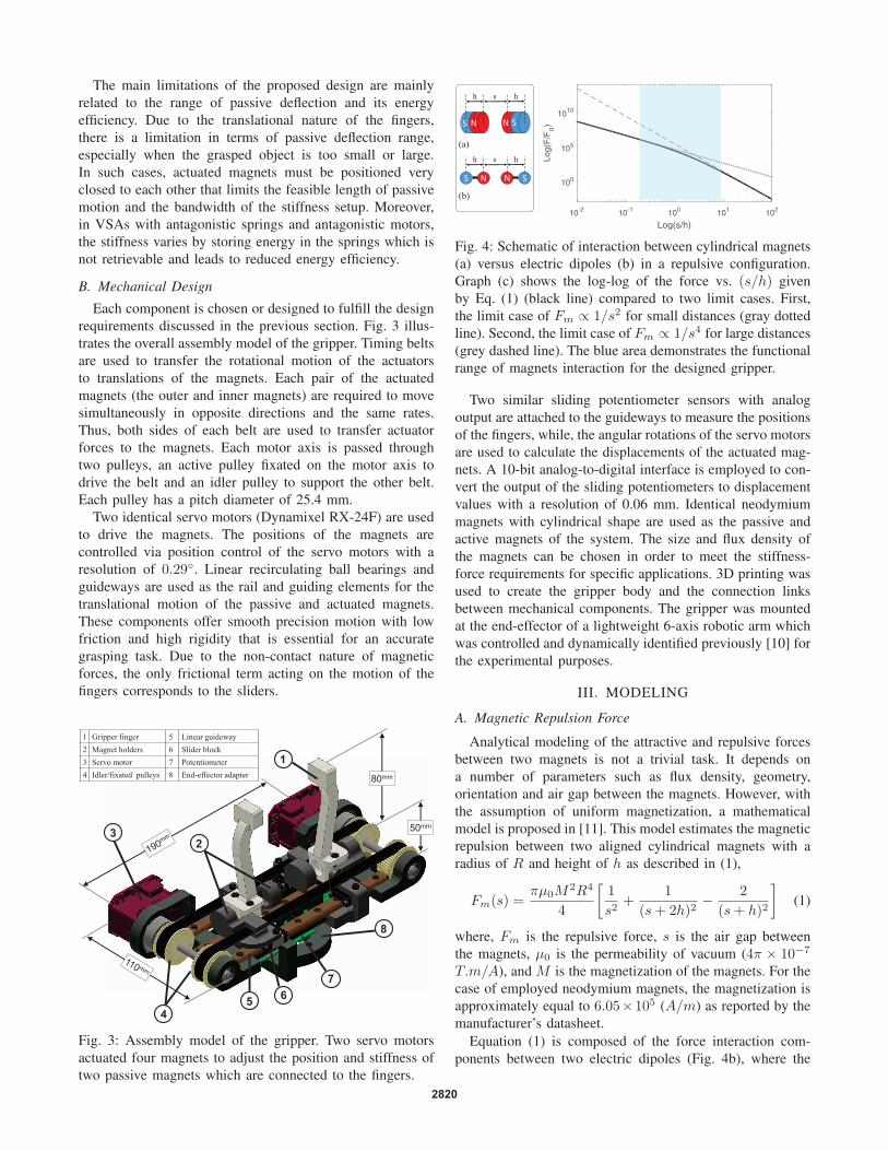
B. Mechanical Design
Each component is chosen or designed to fulfill the design
requirements discussed in the previous section. Fig. 3 illus-
trates the overall assembly model of the gripper. Timing belts
are used to transfer the rotational motion of the actuators
to translations of the magnets. Each pair of the actuated
magnets (the outer and inner magnets) are required to move
simultaneously in opposite directions and the same rates.
Thus, both sides of each belt are used to transfer actuator
forces to the magnets. Each motor axis is passed through
two pulleys, an active pulley fixated on the motor axis to
drive the belt and an idler pulley to support the other belt.
Each pulley has a pitch diameter of 25.4 mm.
Two identical servo motors (Dynamixel RX-24F) are used
to drive the magnets. The positions of the magnets are
controlled via position control of the servo motors with a
resolution of 0.29◦. Linear recirculating ball bearings and
guideways are used as the rail and guiding elements for the
translational motion of the passive and actuated magnets.
These components offer smooth precision motion with low
friction and high rigidity that is essential for an accurate
grasping task. Due to the non-contact nature of magnetic
forces, the only frictional term acting on the motion of the
fingers corresponds to the sliders.
8
7
6
4
3
2
1
50mm
80mm
5
1 Gripper finger 5 Linear guideway
2 Magnet holders 6 Slider block
3 Servo motor 7 Potentiometer
4 Idler/fixated pulleys 8 End-effector adapter
Fig. 3: Assembly model of the gripper. Two servo motors
actuated four magnets to adjust the position and stiffness of
two passive magnets which are connected to the fingers.
S N N S
NS N S
(a)
(b)
sh h
sh h
10-2 10-1 100 101 102
Log(s/h)
100
105
1010
Log(
F/F
0)
Fig. 4: Schematic of interaction between cylindrical magnets
(a) versus electric dipoles (b) in a repulsive configuration.
Graph (c) shows the log-log of the force vs. (s/h) given
by Eq. (1) (black line) compared to two limit cases. First,
the limit case of Fm ∝ 1/s2 for small distances (gray dotted
line). Second, the limit case of Fm ∝ 1/s4 for large distances
(grey dashed line). The blue area demonstrates the functional
range of magnets interaction for the designed gripper.
Two similar sliding potentiometer sensors with analog
output are attached to the guideways to measure the positions
of the fingers, while, the angular rotations of the servo motors
are used to calculate the displacements of the actuated mag-
nets. A 10-bit analog-to-digital interface is employed to con-
vert the output of the sliding potentiometers to displacement
values with a resolution of 0.06 mm. Identical neodymium
magnets with cylindrical shape are used as the passive and
active magnets of the system. The size and flux density of
the magnets can be chosen in order to meet the stiffness-
force requirements for specific applications. 3D printing was
used to create the gripper body and the connection links
between mechanical components. The gripper was mounted
at the end-effector of a lightweight 6-axis robotic arm which
was controlled and dynamically identified previously [10] for
the experimental purposes.
III. MODELING
A. Magnetic Repulsion Force
Analytical modeling of the attractive and repulsive forces
between two magnets is not a trivial task. It depends on
a number of parameters such as flux density, geometry,
orientation and air gap between the magnets. However, with
the assumption of uniform magnetization, a mathematical
model is proposed in [11]. This model estimates the magnetic
repulsion between two aligned cylindrical magnets with a
radius of R and height of h as described in (1),
Fm(s) =πμ0M
2R4
4
[1
s2+
1
(s+ 2h)2− 2
(s+ h)2
](1)
where, Fm is the repulsive force, s is the air gap between
the magnets, μ0 is the permeability of vacuum (4π × 10−7
T.m/A), and M is the magnetization of the magnets. For the
case of employed neodymium magnets, the magnetization is
approximately equal to 6.05×10⁵ (A/m) as reported by the
manufacturer’s datasheet.
Equation (1) is composed of the force interaction com-
ponents between two electric dipoles (Fig. 4b), where the
2820
first term inside the bracket corresponds to the force be-
tween the nearest poles (N-N), the second term denotes the
force between distant poles (S-S) and the third term is the
attraction force between the opposite poles (N-S). Based on
this relation, the repulsion force for large air gaps (s� h) is
proportional to an inverse power law of the form Fm ∝ 1/s4
, while it becomes Fm ∝ 1/s2 for small air gaps (s � h).
This is illustrated in Fig. 4c by the help of a log-log graph.
Since Eq. (1) is based on the assumption of uniform mag-
netization and ideal magnets, an experiment was conducted
to verify the accuracy of this model for the specific case of
our gripper. A force sensor was used to measure the actual re-
pulsive forces between two cylindrical neodymium magnets
in different distances. In this setup, the same linear unit and
guiding elements used in the gripper were used to generate
translational motion between two magnets. This gives the
possibility to investigate the effect of force hysteresis caused
by the friction in a loading and unloading motion.
0 0.005 0.01 0.015
Air Gap (m)
0
5
10
15
20
For
ce (
N)
Loading CurveUnloading CurveMagnetic Depoles Model
Fig. 5: The dotted blue and dashed red curve represent the
measured repulsion force of a loading and unloading motion,
respectively. The black curve demonstrates the corresponding
analytical force given by Eq. (1).
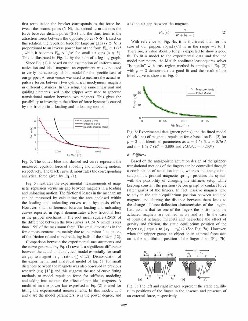
Fig. 5 illustrates the experimental measurements of mag-
netic repulsion versus air gap between magnets in a loading
and unloading motion. The frictional losses in the mechanism
can be measured by calculating the area enclosed within
the loading and unloading curves as a hysteresis effect.
However, small differences between loading and unloading
curves reported in Fig. 5 demonstrates a low frictional loss
in the gripper mechanism. The root mean square (RMS) of
the difference between the two curves is 0.34 N which is less
than 1.5% of the maximum force. The small deviations in the
force measurements are mainly due to the minor fluctuations
of the friction related to recirculating balls of the sliders [12].
Comparison between the experimental measurements and
the curve generated by Eq. (1) reveals a significant difference
between the actual and analytical model especially for small
air gap to magnet height ratios ( sh < 1.5). Disassociation of
the experimental and analytical model of Eq. (1) for small
distances between the magnets was also observed in previous
research (e.g. [13]) and this suggests the use of curve fitting
methods to model repulsion force for stiffness modeling
and taking into account the effect of non-ideal magnets. A
modified inverse power law expressed in Eq. (2) is used for
fitting the experimental measurements. In this model, a, band c are the model parameters, p is the power degree, and
s is the air gap between the magnets.
Fm(s) =a
sp + bs+ c(2)
With reference to Fig. 4c, it is illustrated that for the
case of our gripper, log10(s/h) is in the range −1 to 1.
Therefore, a value about 3 for p is expected to show a good
fit. To fit a model to the experimental data and find the
model parameters, the Matlab nonlinear least-squares solver
“lsqnonlin” with trust-region method is employed. Eq. (2)
with p = 3 demonstrated a good fit and the result of the
fitted curve is shown in Fig. 6.
0 0.005 0.01 0.015
Air Gap (m)
0
10
20
For
ce (
N)
MeasurementsFitted Model
Fig. 6: Experimental data (green points) and the fitted model
(black line) of magnetic repulsion force based on Eq. (2) for
p = 3 and identified parameters as a = 4.5e-6, b = 8.7e-5and c = 1.5e-7 (R2 = 0.998 and RMSE = 0.29N )
B. Stiffness
Based on the antagonistic actuation design of the gripper,
translational motions of the fingers can be controlled through
a combination of actuation inputs, whereas the antagonistic
setup of the preload magnetic springs provides the system
with the possibility of changing the stiffness setup while
keeping constant the position (before grasp) or contact force
(after grasp) of the fingers. In fact, passive magnets tend
to stay in the static equilibrium position between actuated
magnets and altering the distance between them leads to
the change of force-deflection characteristics of the fingers.
Lets assume that for one of the fingers the positions of the
actuated magnets are defined as x1 and x2. In the case
of identical actuated magnets and neglecting the effect of
gravity and friction, the static equilibrium position of the
finger (xf ) equals to (x1 + x2)/2 (See Fig. 7a). However,
when the gripper grasps an object or an external force acts
on it, the equilibrium position of the finger alters (Fig. 7b).
x1 x2xf
wmwm wf
Fe
s1 d12 s2
(a) (b)
Fig. 7: The left and right images represent the static equilib-
rium positions of the finger in the absence and presence of
an external force, respectively.
2821
Considering the magnet repulsion as the main forcing factor,
the following static equation holds,∑F = Fe + Fm1 + Fm2 = 0 (3)
where, Fe is the external force and Fm1 and Fm2 denote
repulsive forces of the actuated magnets associated with
coordinates x1 and x2. By considering the magnetic re-
pulsion as a function of air gap between the magnets and
substituting (2) in (3), the magnitude of the external force
can be estimated as Fm(s1)− Fm(s2) shown in (4),
Fe(s1, s2) =1
s31 + bs1 + c− 1
s32 + bs2 + c(4)
where, sn denotes the distance from surfaces of the actuated
magnet n to the passive magnet illustrated in Fig. 7, while a,
b and c are the parameters of the fitted model. The stiffness
for a given state can be described using the chain rule,
K(s1, s2) =dFe
dxf=
dFm1
dxf− dFm2
dxf
=dFm1
ds1
ds1dxf
− dFm2
ds2
ds2dxf
= dFm(s1) + dFm(s2) (5)
where,
dFm(s) =−a(3s2 + b)
(s3 + bs+ c)2(6)
The distances between magnets (s1 and s2) can be calcu-
lated in terms of magnet positions (x1, x2 and xf ) as follows,
s1 = xf − x1− 0.5(wm + wf ) (7)
s2 = x2 − xf − 0.5(wm + wf ) (8)
where, wm and wf are the width of the holders of actuated
and passive magnets, respectively, as shown in Fig. 7. Conse-
quently, the above expressions of the force and stiffness can
be rewritten as a function of the positions of the actuated
and passive magnets. For the presented design, the magnet
positions can be easily measured from motor rotations and
sliding potentiometer sensors.
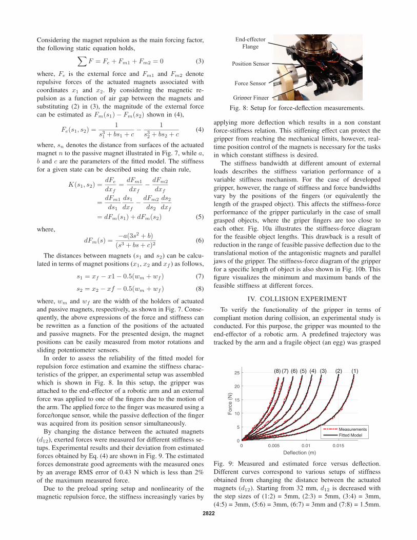
In order to assess the reliability of the fitted model for
repulsion force estimation and examine the stiffness charac-
teristics of the gripper, an experimental setup was assembled
which is shown in Fig. 8. In this setup, the gripper was
attached to the end-effector of a robotic arm and an external
force was applied to one of the fingers due to the motion of
the arm. The applied force to the finger was measured using a
force/torque sensor, while the passive deflection of the finger
was acquired from its position sensor simultaneously.
By changing the distance between the actuated magnets
(d12), exerted forces were measured for different stiffness se-
tups. Experimental results and their deviation from estimated
forces obtained by Eq. (4) are shown in Fig. 9. The estimated
forces demonstrate good agreements with the measured ones
by an average RMS error of 0.43 N which is less than 2%
of the maximum measured force.
Due to the preload spring setup and nonlinearity of the
magnetic repulsion force, the stiffness increasingly varies by
Force Sensor
End-effector
Flange
Gripper Finger
Position Sensor
Fig. 8: Setup for force-deflection measurements.
applying more deflection which results in a non constant
force-stiffness relation. This stiffening effect can protect the
gripper from reaching the mechanical limits, however, real-
time position control of the magnets is necessary for the tasks
in which constant stiffness is desired.
The stiffness bandwidth at different amount of external
loads describes the stiffness variation performance of a
variable stiffness mechanism. For the case of developed
gripper, however, the range of stiffness and force bandwidths
vary by the positions of the fingers (or equivalently the
length of the grasped object). This affects the stiffness-force
performance of the gripper particularly in the case of small
grasped objects, where the griper fingers are too close to
each other. Fig. 10a illustrates the stiffness-force diagram
for the feasible object lengths. This drawback is a result of
reduction in the range of feasible passive deflection due to the
translational motion of the antagonistic magnets and parallel
jaws of the gripper. The stiffness-force diagram of the gripper
for a specific length of object is also shown in Fig. 10b. This
figure visualizes the minimum and maximum bands of the
feasible stiffness at different forces.
IV. COLLISION EXPERIMENT
To verify the functionality of the gripper in terms of
compliant motion during collision, an experimental study is
conducted. For this purpose, the gripper was mounted to the
end-effector of a robotic arm. A predefined trajectory was
tracked by the arm and a fragile object (an egg) was grasped
0 0.005 0.01 0.015
Deflection (m)
0
5
10
15
20
25
For
ce (
N)
(1)(2)(3)(4)(5)(6)(7)(8)
MeasurementsFitted Model
Fig. 9: Measured and estimated force versus deflection.
Different curves correspond to various setups of stiffness
obtained from changing the distance between the actuated
magnets (d12). Starting from 32 mm, d12 is decreased with
the step sizes of (1:2) = 5mm, (2:3) = 5mm, (3:4) = 3mm,
(4:5) = 3mm, (5:6) = 3mm, (6:7) = 3mm and (7:8) = 1.5mm.
2822
0 5 10 15 20 25
Force (N)
0
0.5
1
1.5
2
2.5
Stif
fnes
s (N
/m)
104
(b)
Fig. 10: a) the stiffness-force relation for the feasible range
of object lengths. b) Cross section of for object length of
8cm. The lower and upper curves demonstrate the stiffness
bandwidth in the range of feasible forces.
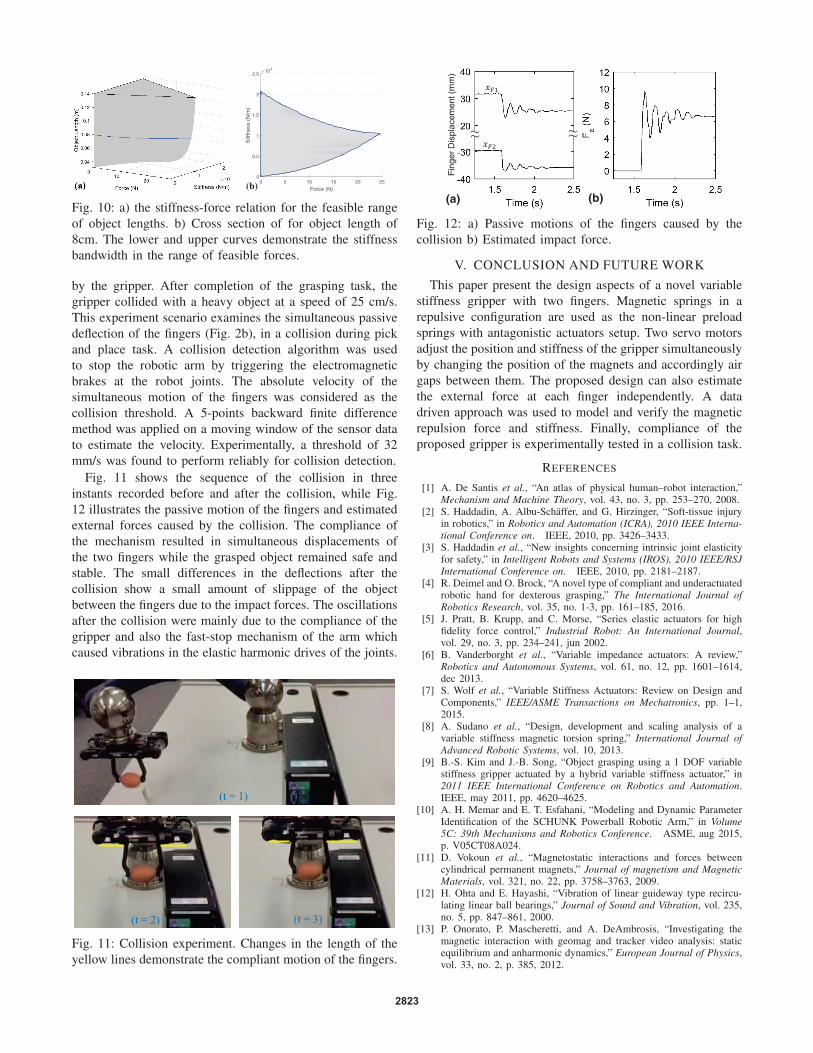
by the gripper. After completion of the grasping task, the
gripper collided with a heavy object at a speed of 25 cm/s.
This experiment scenario examines the simultaneous passive
deflection of the fingers (Fig. 2b), in a collision during pick
and place task. A collision detection algorithm was used
to stop the robotic arm by triggering the electromagnetic
brakes at the robot joints. The absolute velocity of the
simultaneous motion of the fingers was considered as the
collision threshold. A 5-points backward finite difference
method was applied on a moving window of the sensor data
to estimate the velocity. Experimentally, a threshold of 32
mm/s was found to perform reliably for collision detection.
Fig. 11 shows the sequence of the collision in three
instants recorded before and after the collision, while Fig.
12 illustrates the passive motion of the fingers and estimated
external forces caused by the collision. The compliance of
the mechanism resulted in simultaneous displacements of
the two fingers while the grasped object remained safe and
stable. The small differences in the deflections after the
collision show a small amount of slippage of the object
between the fingers due to the impact forces. The oscillations
after the collision were mainly due to the compliance of the
gripper and also the fast-stop mechanism of the arm which
caused vibrations in the elastic harmonic drives of the joints.
(t = 1)
(t = 2) (t = 3)
Fig. 11: Collision experiment. Changes in the length of the
yellow lines demonstrate the compliant motion of the fingers.
~~ ~~
Fin
ger
Dis
plac
emen
t (m
m)
(a) (b)
Fig. 12: a) Passive motions of the fingers caused by the
collision b) Estimated impact force.
V. CONCLUSION AND FUTURE WORK
This paper present the design aspects of a novel variable
stiffness gripper with two fingers. Magnetic springs in a
repulsive configuration are used as the non-linear preload
springs with antagonistic actuators setup. Two servo motors
adjust the position and stiffness of the gripper simultaneously
by changing the position of the magnets and accordingly air
gaps between them. The proposed design can also estimate
the external force at each finger independently. A data
driven approach was used to model and verify the magnetic
repulsion force and stiffness. Finally, compliance of the
proposed gripper is experimentally tested in a collision task.
REFERENCES
[1] A. De Santis et al., “An atlas of physical human–robot interaction,”Mechanism and Machine Theory, vol. 43, no. 3, pp. 253–270, 2008.
[2] S. Haddadin, A. Albu-Schaffer, and G. Hirzinger, “Soft-tissue injuryin robotics,” in Robotics and Automation (ICRA), 2010 IEEE Interna-tional Conference on. IEEE, 2010, pp. 3426–3433.
[3] S. Haddadin et al., “New insights concerning intrinsic joint elasticityfor safety,” in Intelligent Robots and Systems (IROS), 2010 IEEE/RSJInternational Conference on. IEEE, 2010, pp. 2181–2187.
[4] R. Deimel and O. Brock, “A novel type of compliant and underactuatedrobotic hand for dexterous grasping,” The International Journal ofRobotics Research, vol. 35, no. 1-3, pp. 161–185, 2016.
[5] J. Pratt, B. Krupp, and C. Morse, “Series elastic actuators for highfidelity force control,” Industrial Robot: An International Journal,vol. 29, no. 3, pp. 234–241, jun 2002.
[6] B. Vanderborght et al., “Variable impedance actuators: A review,”Robotics and Autonomous Systems, vol. 61, no. 12, pp. 1601–1614,dec 2013.
[7] S. Wolf et al., “Variable Stiffness Actuators: Review on Design andComponents,” IEEE/ASME Transactions on Mechatronics, pp. 1–1,2015.
[8] A. Sudano et al., “Design, development and scaling analysis of avariable stiffness magnetic torsion spring,” International Journal ofAdvanced Robotic Systems, vol. 10, 2013.
[9] B.-S. Kim and J.-B. Song, “Object grasping using a 1 DOF variablestiffness gripper actuated by a hybrid variable stiffness actuator,” in2011 IEEE International Conference on Robotics and Automation.IEEE, may 2011, pp. 4620–4625.
[10] A. H. Memar and E. T. Esfahani, “Modeling and Dynamic ParameterIdentification of the SCHUNK Powerball Robotic Arm,” in Volume5C: 39th Mechanisms and Robotics Conference. ASME, aug 2015,p. V05CT08A024.
[11] D. Vokoun et al., “Magnetostatic interactions and forces betweencylindrical permanent magnets,” Journal of magnetism and MagneticMaterials, vol. 321, no. 22, pp. 3758–3763, 2009.
[12] H. Ohta and E. Hayashi, “Vibration of linear guideway type recircu-lating linear ball bearings,” Journal of Sound and Vibration, vol. 235,no. 5, pp. 847–861, 2000.
[13] P. Onorato, P. Mascheretti, and A. DeAmbrosis, “Investigating themagnetic interaction with geomag and tracker video analysis: staticequilibrium and anharmonic dynamics,” European Journal of Physics,vol. 33, no. 2, p. 385, 2012.
2823