design of a small scale wind generator for low wind …
TRANSCRIPT
DESIGN OF A SMALL SCALE WIND GENERATOR FOR LOW WIND
SPEED AREAS
RA Msuya1, RRM Kainkwa
1 and MI Mgwatu
2
1Departrment of Physics, College of Natural and Applied Sciences, University of Dar es Salaam,
P.O. Box 35065, Dar es Salaam, Tanzania 2Departrment of Mechanical and Industrial Engineering, College of Engineering and Technology,
University of Dar es Salaam, P.O. Box 35131, Dar es Salaam, Tanzania
E-mail: [email protected], Tel: +255 713 350 159
ABSTRACT:
Most small scale level wind turbine generators are directly driven system, variable speed, and
partially connected power electronic converter system. Choice of such system is to avoid costs
associated with gearbox. However, due to low wind speed in most of the tropical countries,
synchronous generators with smaller or medium speed Permanent Magnet (PM) generator design
found to be important and given high performance efficiency. In order to be able to harvest wind
energy in off-grid population efficiently, there was a need to design a synchronous generator that
can be able to operate under low wind speed, directly connected to the end user. Hence, the study
designed a six pole pair wind turbine generator using permanent magnet (PM) model, using
Maxwell two dimensions (2D) and Rotational Machine Expert (RMxrpt) software. The designed
PM AC wind turbine generator worked with efficiency of 93% at rotational speed (rpm) range
from 50 to 350 with maximum power output of 980 watts.
Keywords: Pole Pairs, Performance Characteristics, Permanent Magnet Wind Generator
INTRODUCTION
For wind power applications in particular,
multi-pole permanent magnet generators have
become very attractive especially in small
ratings (Ocak 2012). Permanent magnet
synchronous generators (PM AC) are one of
the best solutions for small-scale wind power
plants. Low-speed multi-pole PM generators
are maintenance-free and may be used in
different climate conditions. Potentially,
permanent magnet generators offer a high
efficiency in operational, simple and robust
(Papathanassiou 1999). Basically, PM AC
generators can be divided into internal and
external machines, according to rotor
direction in the air gap. The availability of
modern high energy density magnet materials
such as NdFeB, has made it possible to design
special topologies (Rizk and Nagrial 2000).
Most wind turbine generators currently
installed in small scale levels are in directly
driven system, variable speed, and partially
rated power electronic converter. Choice of
such system is to avoid the gearbox failures
and leading to long downtimes, gearless full
variable speed PM generators connected to
the end user via a full rated power electronic
converter are considered in several new
installations. However, due to low wind speed
in most of the tropical countries, synchronous
generators with smaller or medium speed PM
generator designs found to be important and
given high consideration. In order to reduce
the complexity of the drive train there are
experimental proposals in literature where a
synchronous generator that be able to operate
under low wind speed can be directly
connected to the end user
especially the off-grid population. Hence, the
study designed a six pole pairs wind turbine
generator using permanent magnet (PM)
model and analysing it for small scale wind
power harvesting at low wind speed area,
using Maxwell two dimensions (2D) and
Tanz. J. Sci. Vol. 43(1) 2017
137
Rotational Machine Expert (RMxrpt)
software.
MATERIAL AND METHODS
Permanent Magnet Generator Model
The Permanent Magnet Synchronous
Generator (PMSG) is a machine whose
excitation depends on the permanent magnet
instead of the use of DC power. The
excitation is normally associated with some
losses, where for small machine excitation
losses may reach up to 5 % (Ayehunie 2011).
The PM synchronous machine is designed in
such a way that the permanent magnets are in
the rotor surface, where it is separated by the
air gap with stator containing windings. The
PMSG is very useful for wind turbine
applications because it is smaller in physical
size, has a higher efficiency and reliability
and it also has high power output, though it
lacks voltage control due to their constant
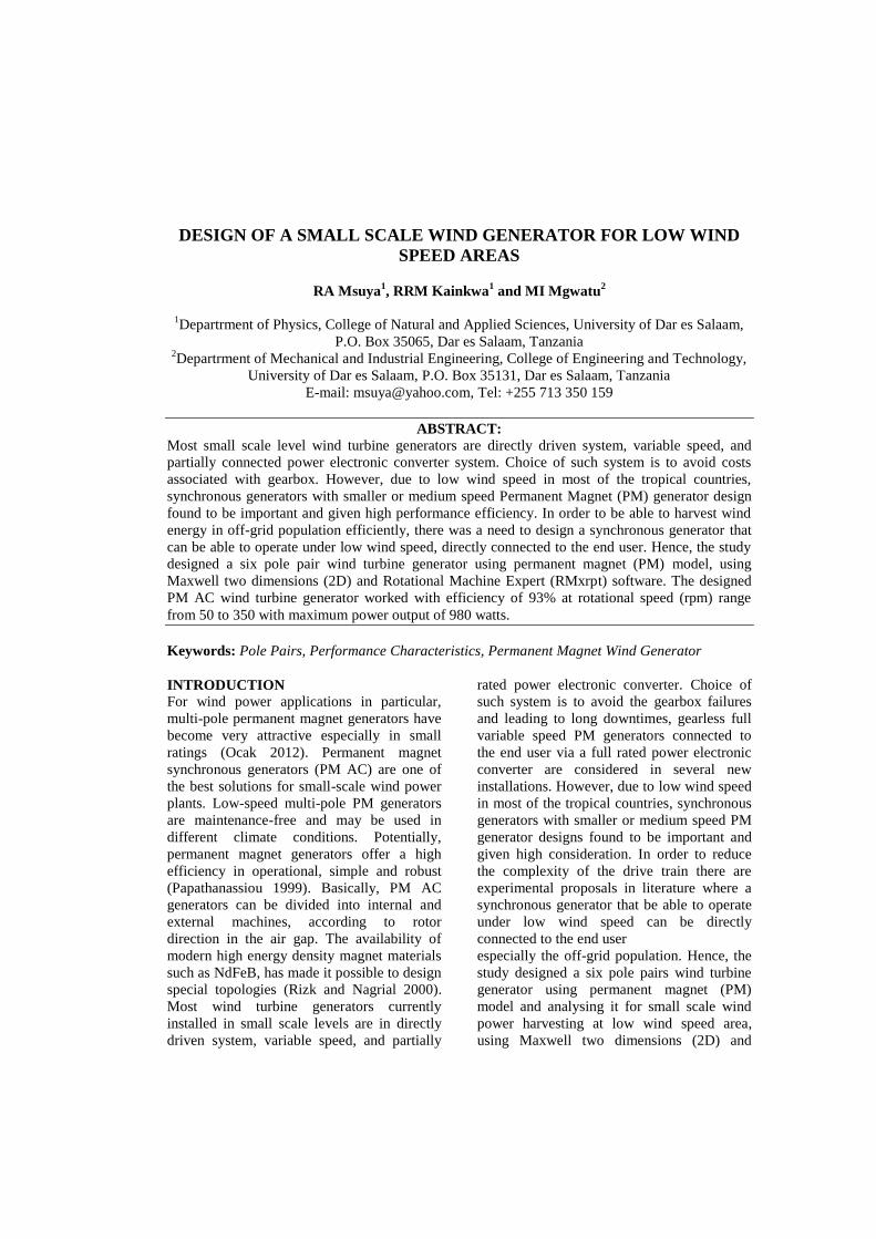
excitation. This is one layout of PM generator,
but there are several designs, like radial flux
inner rotor, radial flux outer rotor, and axial
flux. With reference to all these designs of
PM generator, flux crosses the air gap from
the rotor to the stator in the radial direction
(Rucker 2005). This type of design is known
as AC synchronous generator and this is as
shown in Fig. 1.
Figure 1: The configuration design of AC Synchronous wind turbine generator (source: Rucker
2005)
Generator Performance Efficiency
Many authors have discussed several
procedures and methods of finding the
efficiency of the wind turbine generators and
general performance of wind generator. The
major consideration is the input mechanical
power to the generator with the output
electrical power and loss conditions of
generator that can be determined from
rotating speed of the machine (Tamura and
Muyeen 2012). Both suggested that the
efficiency of the generator can be determined
using the ratio of total output power Po to the
total input power Pin. The mechanical losses
and stray load loss cannot be expressed in a
generator equivalent circuit, but they can be
deducted from the wind generator output.
Wind speed was taken as mechanical input
power to the system, where power produced
were multiplied by the gearbox efficiency, but
Msuya et al. - Design of a small scale wind generator for low wind speed areas
138
this should be for non-direct driven systems.
The mechanical loss and stray loss were then
deducted from the wind turbine output power.
The external characteristic of the generator
performance is considered as most important
as it gives the relationship between the
terminal voltage against output current and
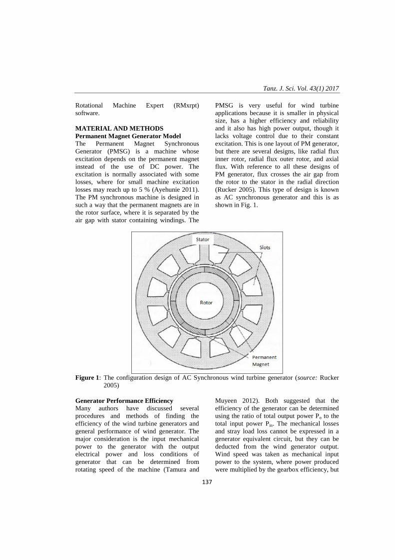
the resistive load (Guo et al. 2008). From the
phase output equivalent electrical circuit of
the generator shown in Fig. 2, the external
characteristic can be derived as (Guo et al.
2008):
)cossin(
)sincos( 222
ggg
gg
RLI
RLIEV
(1
where V is the terminal voltage and E is the
back Emf. Ig is the the load current, while ω
is equivqlent to 2πf, which is angular
frequency of the electricity. Lg is inductance
and Rg is the phase resistance, while θ is the
power factor of the load.
Ig
R g jω Lg
EV
Figure 2: PM AC generator phase equivalent circuit
With reference to Equation (1), the external
characteristics of the PM synchronous
generator can be achieved when the load
resistance is varied. During the variation of
the load resistance the external behaviour of
the current and voltage can be realised, which
determine the generator characteristics. If the
equivalent electrical circuit is considered, the
electrical output power, the mechanical input
power, input mechanical torque, and
efficiency of the PM generator can be
calculated per phase (Guo et al. 2008) as:
cos3 gVIoP (2)
Hence the total mechanical input power can
then be computed as:
mecPFePcuPoPinP (3)
where Pcu is copper loss, PFe is iron loss and
Pmec is mechanical loss.
The efficiency therefore can be evaluted from
equations (2) and (3) as:
inP
outP . (4)
Modeling and Simulation of Permanent
Magnet Synchronous Generator
Many softwares have been used to develop
modeling the rotating electrical machines like
generators. The most used softwares include
Maple-software, HOMER software, Matlab,
Gridlab-D Comsol and Maxwell. In this study
Maxwell software was used in modeling the
Tanz. J. Sci. Vol. 43(1) 2017
139
PM AC synchronus machine. This is premier
electromagnetic field simulation software for
scientists and engineers used in the designing
and analysing 3-Dimension (3D) and 2-
Dimension (2D) electromagnetic and
electromechanical devices that includes
generator, motors, actuators, transformers,
sensors and coils (Liping 2012). The
simulation model actually display the real
situation in a simpler form, when the basic
characteristics and the parameters of the
machine are employed and analysed. In order
to be able to use the Maxwell software, it is
important to review the fundamental
electromagnetic theories and application [9].
Some of these theorems includes the general
theory of electromagnetic phenomena based on
Maxwell’s equations, which is a set of first-
order vector partial-differential equations
which relates the space and time changes of
electric and magnetic fields to the scalar
(divergence) and vector source densities. The
Maxwell’s equations in differential and integral
forms that needed to be considered while
dealing with Maxwell software includes Gauss’
law of electric fields (Martin 2007):
),(,. trtrD
(5)
where ∇ is divergence, which is a vector
operator, which measures the magnitude of a
vector field's source or sink at a given point, in
terms of scalar quantity.
Sometimes the divergence represents the
volume density of the outward fluxof a vector
field from an infinite volume around a given
point and ),( tr
is the macroscopic densities
of free-charge or net magnetic charge density.
The designing was based in the Fnite Element
Methodology (FEM) while the simulations
was done to analyse the performance
characteristics of the generator. The
simulations involved the electromagnetic
generator model and equations that represent
electric circuit for the solution of finite
element. The generator parameters were
involved including the stator winding of the
generator, which consists of circular cables
and the rotor surface mounted, power, phase
voltage, no load phase voltage, electrical
current, electrical frequency, load resistance,
load angle and overall efficiency.
The modeling that used the Maxwell Equation
in 2D considered the assumption that the
electromagnetic field inside the generator is
axi-symmetrical. The effect of the 3D
consideretion is such that it has effects like
end region fields impedances in the circuit
equations of the windings. The modeling
developed involved the surface current source
and the electromagnetic described by
magnetic field and circuit equation from
Maxwell’s equation (Leijon et al. 2013):
z
VzA
rot
zA
1. (6)
where, σ is the conductivity, µo vacuum
permeability and µr relative permeability, Az
is the axial magnetic potential and z
V
is the
applied potential.
Permanent Magnet AC Synchronous
Generator Design
The general design of the PM AC Synchronous
generator was based on the improvement of
power output efficiency and to be able to
operate efficiently in low wind speed area. The
important generator parameters as an input to
the maxwell software were as shown in Table1.

Msuya et al. - Design of a small scale wind generator for low wind speed areas
140
Table 1: The locally PM AC generator parameter values
S/No Parameters Values (mm)
1 Rotor - Outer Diameter 111mm
2 Rotor - Inner Diameter 32 mm
3 PM magnet size 10x30x47 mm
4 Rotor Length 60 mm
5 Shaft Diameter 32mm
6 Number of winding 100
7 Copper Wire Diameter 1 mm
8 Number of Magnetic Poles 6
9 Air gap 36 mm
10 Number of slots 48
11 Slots size See Figure 3
12 Stator - Outer Diameter 198 mm
13 Stator - inner Diameter 118mm
14 Core Pitch 5
The slot size is as shown in
Figure 3:
BsO = 1.5 mm
Bs1 = 5mm
Bs2 = 8mm
HsO = 1.5mm
Hs2 = 25mm
Figure 3 The Local Generator Slot Size
The designing considered fill factor, s, wich
is the extent that the conductor occupies the
cross-sectional area on the slot determined the
relation (Rucker 2005):
AreaSlotTotal
AreaWindings (7)
The impact of phase numbers can be realized
in the power, current, and voltage ratings of
the machine. For the fixed power, the phase
number is proportional to the increase in
voltage and the decrease in current or the
increase in current and decrease voltage. In
most cases higher phases are used more in
generators than in motors due to connection to
power electronics conversion form AC to DC
and vice versa (Dogan et al. 2011).
Number of slots per pole and per phase is
important parameter in generator design since

Tanz. J. Sci. Vol. 43(1) 2017
141
it is used to determine the interactions
relationship between the rotor poles and the
stator windings. The fractional slot of the
machine ‘m’ can be obtained through the
relation (Rucker 2005):
pq
sNm
2 (8)
where Ns is number of slots, p represents pole
pairs and q the number of phases.
The magnetic height and the air gap normally
have the greater impact to the machine if not
well designed, since they all affect the air-gap
flux density (Bg) and hence induced voltage in
the coils. The effect can easily be revealed in
as (Rucker 2005):
rB
agmh
mhgB
(9)
where hm is magnet height (mm), ag is air
gap (mm) and Br is magnet remnant
flux density (T). Figure 4 shows
Stator winding phase connections
while Figure 5 illustrates a 6 Pole
Pairs Generator
Figure 4: Stator winding phase connections
Msuya et al. - Design of a small scale wind generator for low wind speed areas
142
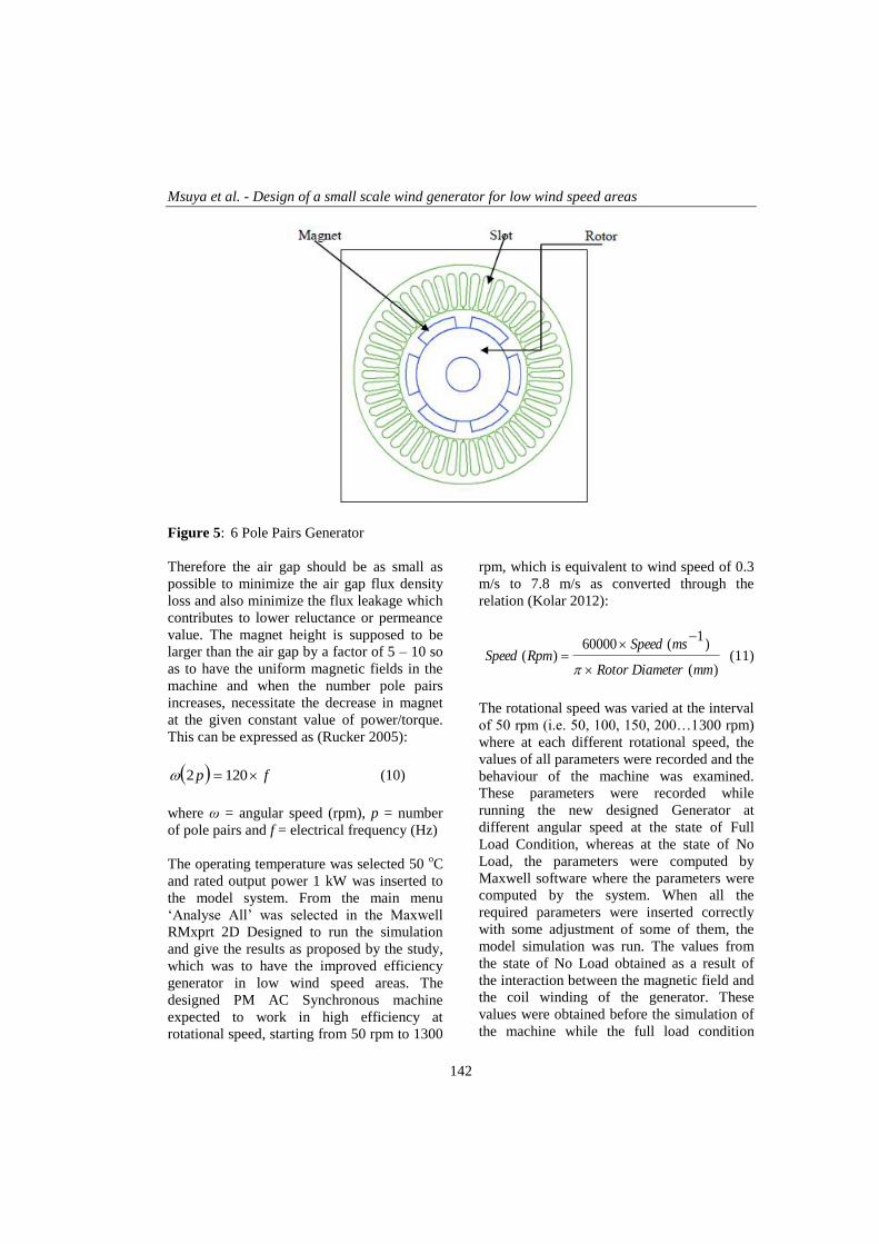
Figure 5: 6 Pole Pairs Generator
Therefore the air gap should be as small as
possible to minimize the air gap flux density
loss and also minimize the flux leakage which
contributes to lower reluctance or permeance
value. The magnet height is supposed to be
larger than the air gap by a factor of 5 – 10 so
as to have the uniform magnetic fields in the
machine and when the number pole pairs
increases, necessitate the decrease in magnet
at the given constant value of power/torque.
This can be expressed as (Rucker 2005):
fp 1202 (10)
where ω = angular speed (rpm), p = number
of pole pairs and f = electrical frequency (Hz)
The operating temperature was selected 50 oC
and rated output power 1 kW was inserted to
the model system. From the main menu
‘Analyse All’ was selected in the Maxwell
RMxprt 2D Designed to run the simulation
and give the results as proposed by the study,
which was to have the improved efficiency
generator in low wind speed areas. The
designed PM AC Synchronous machine
expected to work in high efficiency at
rotational speed, starting from 50 rpm to 1300
rpm, which is equivalent to wind speed of 0.3
m/s to 7.8 m/s as converted through the
relation (Kolar 2012):
)(
)1
(60000)(
mmDiameterRotor
msSpeedRpmSpeed
(11)
The rotational speed was varied at the interval
of 50 rpm (i.e. 50, 100, 150, 200…1300 rpm)
where at each different rotational speed, the
values of all parameters were recorded and the
behaviour of the machine was examined.
These parameters were recorded while
running the new designed Generator at
different angular speed at the state of Full
Load Condition, whereas at the state of No
Load, the parameters were computed by
Maxwell software where the parameters were
computed by the system. When all the
required parameters were inserted correctly
with some adjustment of some of them, the
model simulation was run. The values from
the state of No Load obtained as a result of
the interaction between the magnetic field and
the coil winding of the generator. These
values were obtained before the simulation of
the machine while the full load condition

Tanz. J. Sci. Vol. 43(1) 2017
143
values were obtained during the simulation
process. The design was repeated several
times so as to minimize some errors.
RESULTS AND DISCUSSION
The Maxwell 2D software and RMxprt output
graph for the moving torque of generators is
shown in Figure 6. The moving torque as
observed the machine with 6 pole pairs
decreased from zero to around -35 Nm and
then increased to -32 Nm after which the
moving torque tended to be sinusoidal.
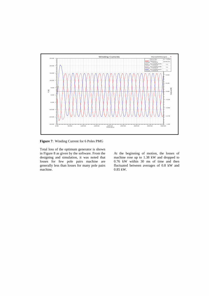
Figure 7 shows winding current for the 6
poles generator as a function of time. The
figure 8 shows that current in the winding of
the machine changes from ± 22.8 A and then
drops to ±18 A and continue in a smooth
sinusoidal curve for all 3 phases. current loss
in the windings seems to be very small that
can be neglected.
0.00 50.00 100.00 150.00 200.00 250.00 300.00 350.00 400.00Time [ms]
-35.00
-30.00
-25.00
-20.00
-15.00
-10.00
-5.00
0.00
Mov
ing1
.Tor
que
[New
tonM
eter
]
Maxwell2DDesign2Torque
Curve Info
Moving1.TorqueSetup1 : Transient
Figure 6: Moving Torque for 6 Pole PMG
0.00 50.00 100.00 150.00 200.00 250.00 300.00 350.00 400.00Time [ms]
-20.00
-15.00
-10.00
-5.00
0.00
5.00
10.00
15.00
20.00
25.00
Y1 [A
]
-1.00
-0.75
-0.50
-0.25
0.00
0.25
0.50
0.75
1.00
Cor
eLos
s [fW
]
Maxwell2DDesign2Winding Currents
Curve Info Y Axis
CoreLossSetup1 : Transient
CoreLoss
Current(PhaseA)Setup1 : Transient
Y1
Current(PhaseB)Setup1 : Transient
Y1
Current(PhaseC)Setup1 : Transient
Y1
Figure 7: Winding Current for 6 Poles PMG
Total loss of the optimum generator is shown
in Figure 8 as given by the software. From the
designing and simulation, it was noted that
losses for few pole pairs machine are
generally less than losses for many pole pairs
machine.
At the beginning of motion, the losses of
machine rose up to 1.38 kW and dropped to
0.76 kW within 30 ms of time and then
fluctuated between averages of 0.8 kW and
0.85 kW.
Tanz. J. Sci. Vol. 43(1) 2017
145
0.00 50.00 100.00 150.00 200.00 250.00 300.00 350.00 400.00Time [ms]
-35.00
-30.00
-25.00
-20.00
-15.00
-10.00
-5.00
0.00
Mov
ing1
.Tor
que
[New
tonM
eter
]
Maxwell2DDesign2Torque
Curve Info
Moving1.TorqueSetup1 : Transient
Fig.ure 8: Total Loss for 6 Pole Pairs PMG
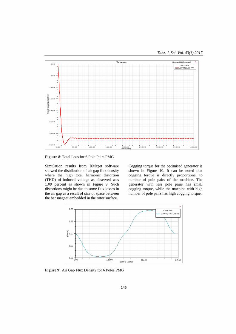
Simulation results from RMxprt software
showed the distribution of air gap flux density
where the high total harmonic distortion
(THD) of induced voltage as observed was
1.09 percent as shown in Figure 9. Such
distortions might be due to some flux losses in
the air gap as a result of size of space between
the bar magnet embedded in the rotor surface.
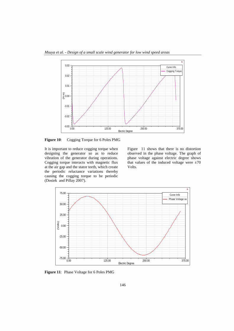
Cogging torque for the optimised generator is
shown in Figure 10. It can be noted that
cogging torque is directly proportional to
number of pole pairs of the machine. The
generator with less pole pairs has small
cogging torque, while the machine with high
number of pole pairs has high cogging torque.
0.00 125.00 250.00 375.00Electric Degree
-0.50
-0.25
0.00
0.25
0.50
(Tesla
)
Curve Info
Air-Gap Flux Density
Figure 9: Air Gap Flux Density for 6 Poles PMG
Msuya et al. - Design of a small scale wind generator for low wind speed areas
146
0.00 125.00 250.00 375.00Electric Degree
-0.03
-0.02
-0.01
0.00
0.01
0.02
0.03(N
.m)
Curve Info
Cogging Torque
Figure 10: Cogging Torque for 6 Poles PMG
It is important to reduce cogging torque when
designing the generator so as to reduce
vibration of the generator during operations.
Cogging torque interacts with magnetic flux
at the air gap and the stator teeth, which create
the periodic reluctance variations thereby
causing the cogging torque to be periodic
(Dosiek and Pillay 2007).
Figure 11 shows that there is no distortion
observed in the phase voltage. The graph of
phase voltage against electric degree shows
that values of the induced voltage were ±70
Volts.
0.00 125.00 250.00 375.00Electric Degree
-75.00
-50.00
-25.00
0.00
25.00
50.00
75.00
(Volts)
Curve Info
Phase Voltage va
Figure 11: Phase Voltage for 6 Poles PMG

Distortion of line current was so small such
that it could not be clearly observed as
depicted in Figure 12, but the resultant current
THD was easily noticed. The small distortion
was seen in the 6 poles machine, but very
little distortion was observed as pole pairs
increases. Such distortion was due to wide
space between magnetic bars, which cause
cogging torque.
Generally, the fundamental standard of stator
current waveforms can be expressed as
(Sittisrijan and Ruangsinchaiwanich 2013):
)sin(,...2,1
ntennInmh
I
(12)
where In is a harmonic order of the peak
current and θn is initial phase angle of the
harmonic order phase current, ω is the angular
speed and t is time.
0.00 125.00 250.00 375.00Electric Degree
-20.00
-10.00
0.00
10.00
20.00
(Am
pere
s)
Curve Info
Phase Current ia
Line Current iac
Line Current iba
Line Current icb
Figure 12: Phase and Line Current for 6 Poles PMG
When the stator current is unbalanced, stator
current waveform becomes distorted,
corresponding to the harmonic current
spectrum where some percentage of the total
harmonic distortion (THD) achieved at a
certain level as shown in Figures 12.
Efficiency of the machines was computed by
the software and eventually computed from
the data generated by the software work sheet.
It should be noted that efficiency of the
machine is computed and presented in the
graphs shown in Figure 13 by the Maxwell
software. That was done under reference
speed 350 rpm and rated speed of 1000 rpm.
When there was change in reference speed,
the graphs also changed till the highest value
of efficiency where efficiency started to
decrease slowly with an increase in rotational
speed.
Msuya et al. - Design of a small scale wind generator for low wind speed areas
148
0.00 20.00 40.00 60.00 80.00 100.00 120.00 140.00 160.00 180.00Pow er Angle +3 (degree)
0.00
20.00
40.00
60.00
80.00
100.00(%
)Curve Info
Efficiency
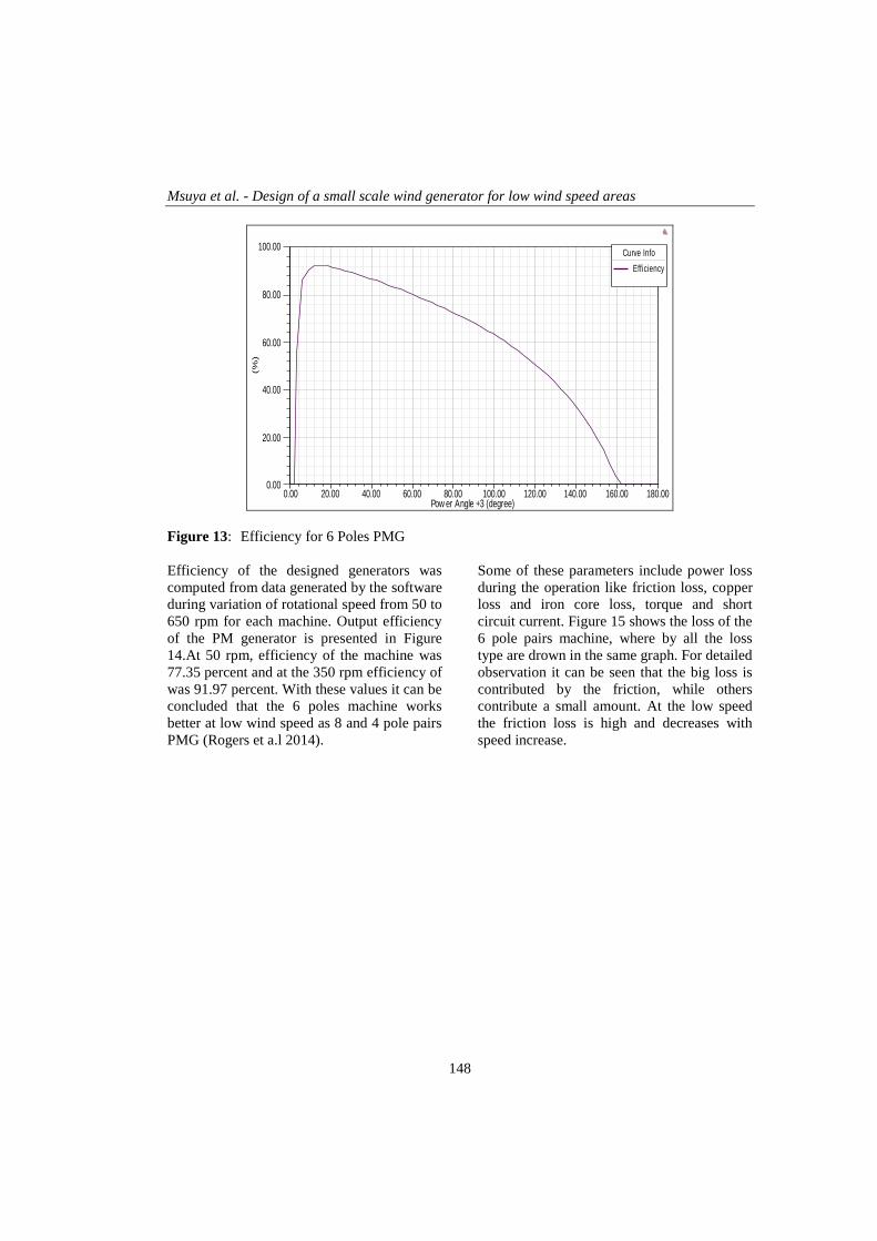
Figure 13: Efficiency for 6 Poles PMG
Efficiency of the designed generators was
computed from data generated by the software
during variation of rotational speed from 50 to
650 rpm for each machine. Output efficiency
of the PM generator is presented in Figure
14.At 50 rpm, efficiency of the machine was
77.35 percent and at the 350 rpm efficiency of
was 91.97 percent. With these values it can be
concluded that the 6 poles machine works
better at low wind speed as 8 and 4 pole pairs
PMG (Rogers et a.l 2014).
Some of these parameters include power loss
during the operation like friction loss, copper
loss and iron core loss, torque and short
circuit current. Figure 15 shows the loss of the
6 pole pairs machine, where by all the loss
type are drown in the same graph. For detailed
observation it can be seen that the big loss is
contributed by the friction, while others
contribute a small amount. At the low speed
the friction loss is high and decreases with
speed increase.

Tanz. J. Sci. Vol. 43(1) 2017
149
0 100 200 300 400 500 600
76
78
80
82
84
86
88
90
92
94
Effic
ien
cy (
%)
Angular Speed (rpm)
Efficiency
Figure 14: The output efficiency for 6 pole pairs PMG
Figure 15: General loss information for 6-pole pairs generator
CONCLUSIONS
The expected output power of the designed
generator was 1 kW, but it was observed that
generator reached the maximum output power
of 980 W at the rotational speed 350 rpm,
which was the rated speed. From the rotational
speed of 450 rpm, the generators produced the
maximum power which is 1000 W, is at the
equivalent to wind speed of 2.7 m/s. This
concluded that the generators are good in terms
of power output, though the machine can be
improved further.
Msuya et al. - Design of a small scale wind generator for low wind speed areas
150
REFERENCE
Ayehunie N 2011 Multi Phase Permanent
Magnet Synchronous Generators for
Offshore Wind Energy System. Control of
six phase PMSG- six leg converter system.
M. Sc. Thesis, Norwegian University of
Science and Technology.
Dogan H, Wurtz F, Foggia A and Garbuio L
2011 Analysis of Slot-Pole Combination of
Fractional-Slots PMSM for Embedded
Applications. Version 1. ACEMP, France.
Dosiek L and Pillay P 2007 Cogging Torque
Reduction in Permanent Magnet Machines.
IEEE Trans. Indust. Appl. 43(6):
Guo Y, Dou Y, Zhu J, Lu H and Jin J 2008
Numerical magnetic field analysis and
computation of a PM synchronous
generator. International Conference on
Electrical Machines and Systems. ICEMS
2008: 2866-2869.
Kolar J, Friedli T, Krismer F, Looser A,
Schweizer M, Steimer P and Bevirt J 2012
Conceptualization and Multi-Objective
Optimization of the Electric System of an
Airborne Wind Turbine. IEEE.org 2: 727-
738.
Leijon M, Ekergard B, Apelfrojd S, de
Santiago J, Bernhoff H, Waters R and
Eriksson S 2013 On a Two Pole Motor for
Electric Propulsion System. Int. J. Engin.
Sci. Innov. Technol. (IJESIT) 2 (1).
Liping G 2012 Stability and Super
Convergence Analysis of ADI-FDTD for
the 2D Maxwell Equations in a Lossy
Medium. Acta Math. Sci. 32 (6): 2341–
2368.
Martin R 2007 Electromagnetic field theory for
physicists and engineers: Fundamentals and
Applications. University of Granada Spain.
Msuya RA, Kainkwa RRM and Mgwatu MI
2014 Comparative Study of the
Performance of Direct-Drive Wind
Generators for Small Scale Wind Turbines.
MIE Conference, Naura Hotel Arusha.
Ocak C, Uygun D, Cetinceviz Y, Demir E and
Gungor Y 2012 Performance Aspects and
Verifications of In-runner and Out-runner
Permanent Magnet Synchronous Generator
Designs of the Same Magnet Structure for
Low Speed Wind Systems. IEEE, Turkey.
3: 1-7.
Papathanassiou S, Kladas G and Papadopoulos
M 1999 Direct-coupled permanent magnet
wind turbine design considerations.
Proceedings of the European Wind Energy
Conference (EWEC’99). P. 10, Nice
(France).
Rizk J and Nagrial M 2000 Design of
permanent-magnet generators for wind
turbines. The Third International Power
Electronics and Motion Control Conference
Proceedings 3: 208-212.
Rucker J 2005 Design and Analysis of a
Permanent Magnet Generator for Naval
Applications. M.Sc. Thesis, Massachusetts
Institute of Technology.
Sittisrijan N and Ruangsinchaiwanich S 2013
Synthesis of Stator Current Waveform of
Induction Motor with Broken Bar
Conditions. International Conference on
Electrical Machines and Systems. Busan,
Korea.
Tamura J and Muyeen S 2012 Wind Energy
Conversion Systems, Green Energy and
Technology. Springer-Verlag London
Limited. Chapter 2.