soma wind generators - wordpress.com the soma wind generators. wind generator usage the soma wind...
TRANSCRIPT
INSTALLATION MANUAL
Version 6.2—Battery Charging Applications
Manufactured by SOMA WIND GENERATORS 8/62 Lords Place, ORANGE NSW 2800 AUSTRALIA
Call us M: 0414 986 830 or M: 0407 669 313 EMAIL [email protected]
somawindgenerators.com.au
Soma Wind Generators

INTRODUCTION This manual provides technical descriptions, specifications and installation procedures for the SOMA wind generators. WIND GENERATOR USAGE The SOMA Wind Generator is a battery charging wind generator to supply power for light duty electrical requirements in remote areas. It is designed to be the main source of power to the energy efficient home covering such loads as lighting, radio, television, water pump,washing machine, kitchen blenders, power tools and refrigeration. The maintenance free features of the SOMA 1000 also make it an ideal source of power to telecommunications and scientific equipment located in inaccessable areas. SOMA wind generators have been designed to be used either as a complementary power supply in conjunction with one or more photovoltaic panels; or in particularly windy areas, as a stand-alone power supply system. SIMPLE INSTALLATION It should take two people no more than two days to complete the installation of the SOMA 1000. Recommendations put forward in this manual should be adhered to as closely as possible. An improper site selection or poor installation can seriosly affect the perform-ance of the system. PLEASE READ THIS MANUAL CAREFULLY BEFORE BEGINNING INSTALLATION. LIST OF COMPONENTS Upon recieving your SOMA you will have the following components that must be assembled together. 1. blade 2. tail pipe 3. tail fin 4. power head 5. propellor bolts 6. nose cone (SOMA 1000 only) 7. controller
THE BLADE The rotor blades are constructed using a hollow moulded fibre glass technique that is inique to Soma. High tensile carbon fibre glass fibres combined with marine grade resins create a modulus for a blade that is both strong and light. Polypropylene tape provides long term erosion protection for the leading edges of the blades. The blade is in one piece which is pre-balanced and fits into location over the boss of the rotor hub. Four bolts are used to secure the blade to the rotor hub. BLADE CHARACTERISTICS SOMA 1000 SOMA 400 Rotor diamenter 2.7 metre 2 metre Chord length: base 125mm 125mm tip 50mm 65mm Pitch at tip 2 degrees 5 degrees Twist 7 degrees 7 degrees Tip speed ratio 10:1 8:1
2

ALTERNATOR The SOMA alternator, which is the main component of the power head is a brushless, directly-driven, alternating current generator which utilizes a rotating permanent magnet field. The alternator is designed to produce a power curve that is optimally suited to the two bladed rotor. The copper windings are impregnated with resin to protect them from corrosion. The rotor shaft is stainless steel with sealed ball bearings (bearing number 6205). The rotor hub is galvanised steel. The rotor hub of the alternator contains the powerful permanent magnets which rotate around the 14 pole stator. The alternator produces 3 phase alternating current (AC) which is converted to direct current (DC) by the Soma Controller which is located near the batteries. SWIVEL ASSEMBLY The swivel assembly rotates and allows the wind generator to face the wind. It also provides the mechanism by which the rotor can tilt back out of the wind to prevent overspeeding. Housed within the swivel assembly are the brushes and slip rings which carry the power to the cable leading to the batteries. It is made of galvanised steel. The swivel assembly fits over the top of a 65mm NB galvanised pipe tower and is secured with 2 bolts. Sealed ball bearings enable free rotation. (Bearing numbers 6206 and 6007). The tail pipe is secured inside the stator boss and the tail vane is bolted to the pipe. THE SOMA CONTROLLER The controller is located near the batteries which can be located up to 750 metres away from the wind generator depending on system voltage and cable size. The controller is a charge regulator which protects the batteries from being overcharged by the wind generator. It contains a voltage sensing mosfet switching device which switches current across to a dump load when ever battery voltage reaches a pre-set point. The controller also contains the rectifier which converts the 3 phase A.C. voltage generated by the SOMA into D.C. voltage suitable for charging the battery. An amp meter indicates the amount of DC current that is charging the battery at any time. FEATHERING MECHANISM The SOMA 1000 utilizes the proven "tilt-up" feathering method to limit rotor speeds in winds in excess of 15ms (metres per second), or 54 kph. It is necessary to limit rotor speed in strong winds to reduce the loads on the wind generator and the tower and to prevent blade wear from overspeeding. The centre of effort of the rotor is above the pivot point of the stator, and wind pressure causes the whole assembly to tilt up. This has the effect of reducing the rotor area presented to the wind, and results in a limitation of the power and rotational speeds achieved by the rotor. The stronger the wind, the further back the rotor tilts. As the wind decreases, gravitational effect pulls the rotor back into normal operating position. A stainless steel hydraulic dampener governs the speed at which the feathering action takes place. This reduces undesirable gyrational action.
3

GALVANISED PIPE WINCH-TILT TOWER These towers, available from Soma Power, come in 4 heights: 6.5m, 13m and 19.5m. The tower consists of 6.5 metre lengths of galvanised pipe supported by guy wires. Generally 2 lengths of pipe are used to provide a 13 metre tower. However, 6.5 metre towers are high enough in very exposed areas such as on a mountain top while a 19.5 metre tower may be required if there are a lot of obstacles nearby affecting the wind. The tower requires concrete foundations and it pivots at the base to enable it to be raised and lowered for ease of installation of the windgenerator and for maintenance. A jockey pole or gin pole is used for leverage to raise the tower and a winch is secured to one of the guy wire foundations to winch the tower up and down. Tower kitsets are available from your SOMA agent which include all of the components necessary except for the lengths of galvanised pipe and the concrete.
The galvanised pipe can also be supplied by Soma Power, but high shipping costs usually mean it is easier and more cost effective for a local steel supplier to supply and pre-drill the poles for you. Drilling details for the poles are supplied in the tower manual to assist local supply. COMPONENTS FOR 13 METRE TOWER
1. upper pipe 3. gin pole 5. joiner tube 7. lower guy wires 9. wire rope grips 11. foundation rings
2. lower pipe 4. hinge bracket 6. upper guy wires 8. rigging screws 10. shackles 6 6
1
5
7 7
2 3
4
8
9
11 10
4

WINCH TOWERS
features tower tilts down to the ground bi-directional brake winch
hot dip galvanised supplied in kit form with or without
19.5m TOWER
benefits
no climbing no towing safe anti corrosion simplifies installation &
maintenance
13m TOWER
SOMA POWER natural power systems
SAFE &
EASY
Specifications
Height 19.5metres Base Dimensions 13.8m x 13.8m Outside Foundations 0.7 x 0.7 x 0.7m Centre Foundation 1 x 1 x 0.25m deep
Specifications
Height 13 metres Base Dimensions 9.2 x 9.2m Outside Foundations 0.6 x 0.6 x 0.6m Centre Foundation 1 x 1 x 0.25m deep
5

gin pole
INSTALLATION &
OPERATION
Available from
SHIPPING INFORMATION Tower kits include everything required except for the poles and concrete. Poles can be supplied by Soma Power, but due to shipping costs, these are normally supplied by your local agent. Specifications for the poles are in the tower kit manual. BOX DIMENSIONS WEIGHT 19.5m kit 700x450x450mm 90kg 19.5m poles 6500x220x220mm 233kg 13m kit 700x450x450mm 60kg 13m poles 6500x160x160mm 120kg
FOUNDATION A comprehensive installation manual is provided with each tower kit. Follow these instructions for laying out the footings. For the 19.5m tower, 1.7m3 of concrete is required, while for the 13m tower, use at least 1.2m3. While the concrete is wet, the foundation brackets are placed in position. Allow at least 48 hours for the concrete to strengthen before raising the tower.
ASSEMBLY Lay out the pipes and guy ropes on the ground in position. Feed the cable up through the centre of the mast, then join the mast sections together using the sleeves provided. Bolt the mast and gin pole to the base plate and shackle all the guy ropes to the mast and base loops. Use the rope grips to set the approximate length of the guy ropes. Raise the tower using the winch and set the guy lengths as required. Adjust the turnbuckles to tighten the guys and make the tower vertical and straight.
WIND GENERATOR Once the tower has been raised and lowered a few times, attach the wind generator and raise it for operation.
MAINTENANCE Wind generator maintenance now becomes a simple, safe half hour operation.
Raising & lowering the Tower
6
steel guy joiner
mast
winch
outside foundation
centre foundation
outside foundation
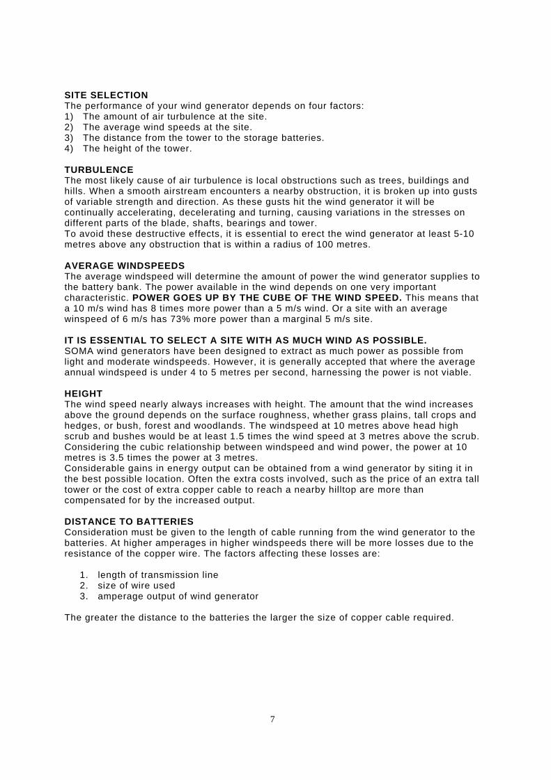
SITE SELECTION The performance of your wind generator depends on four factors: 1) The amount of air turbulence at the site. 2) The average wind speeds at the site. 3) The distance from the tower to the storage batteries. 4) The height of the tower. TURBULENCE The most likely cause of air turbulence is local obstructions such as trees, buildings and hills. When a smooth airstream encounters a nearby obstruction, it is broken up into gusts of variable strength and direction. As these gusts hit the wind generator it will be continually accelerating, decelerating and turning, causing variations in the stresses on different parts of the blade, shafts, bearings and tower. To avoid these destructive effects, it is essential to erect the wind generator at least 5-10 metres above any obstruction that is within a radius of 100 metres. AVERAGE WINDSPEEDS The average windspeed will determine the amount of power the wind generator supplies to the battery bank. The power available in the wind depends on one very important characteristic. POWER GOES UP BY THE CUBE OF THE WIND SPEED. This means that a 10 m/s wind has 8 times more power than a 5 m/s wind. Or a site with an average winspeed of 6 m/s has 73% more power than a marginal 5 m/s site. IT IS ESSENTIAL TO SELECT A SITE WITH AS MUCH WIND AS POSSIBLE. SOMA wind generators have been designed to extract as much power as possible from light and moderate windspeeds. However, it is generally accepted that where the average annual windspeed is under 4 to 5 metres per second, harnessing the power is not viable. HEIGHT The wind speed nearly always increases with height. The amount that the wind increases above the ground depends on the surface roughness, whether grass plains, tall crops and hedges, or bush, forest and woodlands. The windspeed at 10 metres above head high scrub and bushes would be at least 1.5 times the wind speed at 3 metres above the scrub. Considering the cubic relationship between windspeed and wind power, the power at 10 metres is 3.5 times the power at 3 metres. Considerable gains in energy output can be obtained from a wind generator by siting it in the best possible location. Often the extra costs involved, such as the price of an extra tall tower or the cost of extra copper cable to reach a nearby hilltop are more than compensated for by the increased output. DISTANCE TO BATTERIES Consideration must be given to the length of cable running from the wind generator to the batteries. At higher amperages in higher windspeeds there will be more losses due to the resistance of the copper wire. The factors affecting these losses are: 1. length of transmission line 2. size of wire used 3. amperage output of wind generator The greater the distance to the batteries the larger the size of copper cable required.
7

The following table gives maximum transmission length for different cable sizes.
It is usually better to select a site that is further away, if that site has more wind. The copper losses are very minimal at low to medium power output levels and the increased outputs in higher winds will outweigh the losses. It is often advisable to install a 110 volt wind generator and then use a transformer beside the batteries to reduce voltage to the required battery volts. This will enable optimum siting of the wind generator while reducing the cost of the cable. Soma transformers are available from Soma Power.
8
cable mm2
S400 12V
S400 24V
S400 32V
S400 48V
S400 110V
S400 120V
S1000 24V
S1000 32V
S1000 48V
S1000 110V
S1000 120V
2.5 - - 31m 71m 375m 446m - - 28m 150m 178m
4 - 28m 50m 114m 600m 713m - 20m 45m 241m 286m
6 - 42m 76m 171m 900m 1070m 17m 30m 68m 361m 429m
10 18m 71m 126m 285m 1500m 29m 50m 114m 602m 716m
16 28m 114m 203m 456m 46m 81m 183m 964m 1145m
25 44m 178m 317m 714m 71m 127m 285m 1506m
35 62m 250m 444m 999m 100m 178m 400m
50 89m 357m 634m 1428m 143m 254m 571m
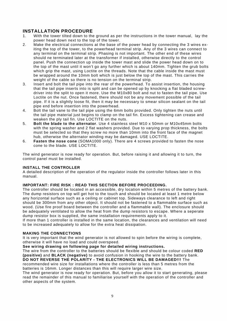
INSTALLATION PROCEDURE 1. With the tower tilted down to the ground as per the instructions in the tower manual, lay the
power head down next to the top of the tower. 2. Make the electrical connections at the base of the power head by connecting the 3 wires ex-
iting the top of the tower, to the powerhead terminal strip. Any of the 3 wires can connect to any terminal on the terminal strip. Phasing is not important. The other end of these wires should ne terminated later at the transformer if installed, otherwise directly to the control panel. Push the connection up inside the tower mast and slide the power head down on to the top of the mast until it won’t go any further which is about 140mm. Tighten the grub bolts which grip the mast, using Loctite on the threads. Note that the cable inside the mast must be wrapped around the 10mm bolt which is just below the top of the mast. This carries the weight of the cable so there is no tension on the terminal strip.
3. Insert and bolt the tail pipe into the rear of the powerhead. To assist insertion, the housing that the tail pipe inserts into is split and can be opened up by knocking a flat bladed screw-driver into the split to open it more. Use the M10x80 bolt and nut to fasten the tail pipe. Use Loctite on the nut. Once fastened, there should not be any movement possible of the tail pipe. If it is a slightly loose fit, then it may be necessary to smear silicon sealant on the tail pipe end before insertion into the powerhead.
4. Bolt the tail vane to the tail pipe using the 6mm bolts provided. Only tighten the nuts until the tail pipe material just begins to clamp on the tail fin. Excess tightening can crease and weaken the ply tail fin. Use LOCTITE on the nuts.
5. Bolt the blade to the alternator. Use 4 stainless steel M10 x 50mm or M10x45mm bolts with the spring washer and 2 flat washers provided. Due to varying prop thickness, the bolts must be selected so that they screw no more than 10mm into the front face of the magnet hub, otherwise the alternator winding may be damaged. USE LOCTITE.
6. Fasten the nose cone (SOMA1000 only). There are 4 screws provided to fasten the nose cone to the blade. USE LOCTITE.
The wind generator is now ready for operation. But, before raising it and allowing it to turn, the control panel must be installed. INSTALL THE CONTROLLER A detailed description of the operation of the regulator inside the controller follows later in this manual. IMPORTANT: FIRE RISK : READ THIS SECTION BEFORE PROCEEDING. The controller should be located in an accessible, dry location within 5 metres of the battery bank. The dump resistors on top will get hot to the touch and should be located at least 1 metre below any horizontal surface such as a ceiling or cabinet top. Sideways clearance to left and right should be 300mm from any other object. It should not be fastened to a flammable surface such as wood. (Use fire proof board between the controller and a flammable wall). The enclosure should be adequately ventilated to allow the heat from the dump resistors to escape. Where a seperate dump resistor box is supplied, the same installation requirements apply to it. If more than 1 controller is installed in the same location, the clearances and ventilation will need to be increased adequately to allow for the extra heat dissipation. MAKING THE CONNECTIONS It is very important that the wind generator is not allowed to spin before the wiring is complete, otherwise it will have no load and could overspeed. See wiring drawing on following page for detailed wiring instructions. The wire from the controller to the batteries should be flexible and should be colour coded RED (positive) and BLACK (negative) to avoid confusion in hooking the wire to the battery bank. DO NOT REVERSE THE POLARITY - THE ELECTRONICS WILL BE DAMAGED!!! The recommended wire size for installations where the controller is less than 5 metres from the batteries is 16mm. Longer distances than this will require larger wire size. The wind generator is now ready for operation. But, before you allow it to start generating, please read the remainder of this manual to familiarise yourself with the operation of the controller and other aspects of the system.
9

SOMA WIRING
BATTERY
BRAKE SWITCH Can be installed on site by installer, or
factory fitted to the controller as an optional extra.
BATTERY VOLTS
SOMA 400
SOMA 1000
12 50A -
24 25A 50A
48 16A 25A
110 / 120 8A 16A
FUSE AMPS
+ -
FUSE
FROM SOMA WIND GENERATOR
The SOMA CONTROLLER is comprised internally of the rectifier and the regulator.
Dump resistors
10
EARTHING The body of the Soma Wind Turbine must be earthed to help protect it from lightning damage. This can be done by earthing the metal tower at it’s base using a 1200mm earth stake and 16mm2 earth wire. The battery negative or positive can also be earthed according to local requirements. For 110 / 120V battery systems, the controller and dump resistor case should be earthed.

REGULATOR FUNCTION AND OPERATION The purpose of the regulator is to prevent the wind generator from overcharging the battery. As a battery is charged it absorbs electric power. Provided that the battery is correctly sized and is in good condition it will absorb power at a high rate (50amps at 24 volts, for example). When the battery is approaching full and the voltage has risen (29 to 30 volts in 24 volt system), the battery will no longer absorb all of the power being fed into it. The excess power heats up the battery and hydrogen sulphide gas is produced. This is an undesirable situation for both the longevity of the battrey and safety. The regulator senses battery voltage and diverts excess current away from the battery to prevent it from overcharging. The FLOAT VOLTAGE is set by the knob on the front of the regulator. If the battery voltage is lower than the float voltage, then the regulator remains off and all of the incoming power goes directly to the battery. As the battery charges up, its voltage increases. When the voltage reaches the float voltage level, the regulator turns on and begins to divert power to the dump load. Provided there is enough power coming from the wind generator, the regulator will send the battery the exact amount of power it needs to maintain its float voltage. As the battery becomes fully charged, almost all of the incoming power is diverted and only the small amount of power needed to maintain the float voltage is allowed to flow into the battery. TO CALIBRATE THE REGULATOR The regulator was installed with the control knob turned fully clockwise. This is the highest voltage setting. By calibrating the position of the knob we will determine the voltage at which the float level is set. Connect a voltmeter to the battery terminals, turn off all appliances and let the wind generator charge up the battery. Keep an eye on the voltmeter while the battery voltage steadily rises. When the desired float voltage is reached, slowly turn the knob anti-clockwise until the red LED float charge indicator begins to glow. The regulator is now set and the voltage will not rise above this point. Observe the battery voltage for a few minutes longer to ensure that the battery voltage does not rise above the desired float voltage. BATTERY VOLTAGES The correct float voltage for lead acid batteries varies with temperature. A 24 volt battery bank should generally have a float voltage of between 27.5 and 29 volts. In cold weather, use the higher figure. The correct float voltage should be obtained from the battery manufacturer. Approximately once a month, the batteries should have an EQUALIZING CHARGE. This, in effect, is a controlled overcharging of the batteries. The purpose is to stir up the elctrolyte in the batteries to prevent stratification. (Stratification is the result of the heavier chemicals in the electrolyte settling at the bottom of the battery and the lighter chemicals rising to the surface. The bubbling that is created by 'overcharging' the batteries in effect stirs up the electrolyte). The equalizing voltage on a 24 volt system can be as high as 30.5 volts. Consult your battery manufacturer! Equalizing may take several hours. A specific gravity of over 1250 indicates that the batteries are well equalized. DO NOT USE OLD OR UNDERSIZED BATTERIES IN YOUR SYSTEM! NO RESPONSIBILITY WILL BE ACCEPTED FOR DAMAGE CAUSED EITHER TO THE CONTROL PANEL ELECTRONICS, OR FOR DAMAGE CAUSED TO EQUIPMENT CONNECTED TO SUB-STANDARD BATTERIES. The minimum recommended battery storage for the SOMA 1000 is 500 amp hours at 24 volts or 250 amp hours at 48 volts.
11

ELECTRICAL BRAKE It is possible to stop the wind generator from turning in the wind by placing a short circuit across the alternator output. This should only be done in light wind speeds to stop the wind generator for servicing, etc. The electrical brake will not stop the wind generator in very strong winds. Any attempt tostop it with the electrical brake in strong winds may result in burning out the alternator windings. If the wind generator has not slowed to less than 20 RPM in less than 1 minute of applying the brake, then it is too windy to attempt to stop the machine and the brake must be released. An electrical brake can be factory fitted as an optional extra. Once the wind generator has stopped the brake will prevent it from starting again even in strong winds. EARTHING The body of the wind turbine must be earthed for lightning protection. This can be done by earthing the base of a metal tower to a nearby earthstake. Use 16mm2 cable between the two. If a wooden tower is used, the short metal stub at the top of the tower which is used for mounting the turbine must be connected to an earth wire which is connected to an earth stake at the bottom of the tower. COMMISSIONING THE WIND GENERATOR When the wiring has been completed, the wind generator can be commissioned. With the electrical brake on, winch up the tower and wind generator into its working position. When the tower is secured in its upright position, release the electrical brake. If there is enough wind the rotor should start spinning and amperage should be registering on the amp meter. The rotor should spin freely and should not shake or vibrate. If any abnormalities are observed, the brake should be re-applied and the unit lowered so that the problem can be analyzed and fixed. Under normal circumstances, the SOMA Wind Generator can now be left unattended to generate power. When the batteries are fully charged, the regulator will divert current to the dump load. MAINTENANCE The SOMA Wing Generator has been designed to be very rugged and durable. As such, the maintenance required is minimal. Along with several visual checks, the only maintenance required is to grease the tilt back bushing and the hydraulic dampener bolts once a year. MAINTENANCE PROCEDURE 1. Engage electrical brake on a light wind day and lower tower. 2. Physically inspect all bolts on the tower and wind generator to ensure that they are secure. 3. Check that the wind generator turns freely and tilts back freely. 4. Check that the blade is in good condition and that it has not been hit or damaged by flying
objects. Replace the protective leading edge tape if necessary. 5. If stiff, the 20mm dia. tilt back bolt will need to be removed and re-coated with DuPont Teflon
White Lithium Greasein the spray can. Available from Repco in Australia. 6. Grease the hydraulic dampener bolts. 7. The hydraulic dampener should be topped up with 20/50 engine oil if it has lost oil. Be sure
that it is not overfilled. The dampener may need to be removed from the machine to do this, as the dampener needs to be filled while in a vertical position. This depends on whether your tower tilts down horizontally. Fill through the top bushing screw hole and fully depress the plunger after filling to squeeze out the excess. Allow the plunger to return to its normal position, then replace the screw. Use loctite on the mounting bolts when replacing the dampener.
8. Observe operation of wind generator. 9. Ensure that the guy wires and rigging screws are securely tightened. Grease the wire ropes
to protect against corrosion if close to a coastal or salty environment.
12

DOS AND DON'TS Please observe the following rules for the operation of your wind generator. They are very important and to disregard them may result in the failure of the wind generator. 1. DO ensure that the site you have selected is free from obstacles that cause turbulent air. 2. DO use copper cable of sufficient diameter for the distance to the batteries. 3. DO ensure that the controller is situated close to the batteries and is in a dry place. Especially make sure there is sufficient ventilation and clearance from flam mable materials to prevent a possible fire risk. 4. DO NOT allow the wind generator to operate while the controller is disconnected from the batteries as it may overspeed. 5. DO NOT climb or lower tower without engaging the electric brake. 6. DO NOT allow the wind generator to operate while it is disconnected from the controller as it may overspeed. 7. DO grease the tilt back bolt once a year using Du Pont Teflon White Lithium Grease in the spray can. Available at Repco in Australia. 8. DO NOT use old or undersized batteries. CONGRATULATIONS! YOU HAVE PURCHASED ONE OF THE FINEST AND MOST RELIABLE WIND GENERATORS AVAILABLE.
13

WARRANTY CONDITIONS Soma Power warrants your Soma1000 / Soma400 to be free of defects in materials and workmanship under normal use and service, for a period of two (2) years. This warranty is available from the date of original purchase. All parts will be replaced or repaired free of charge within this period. This does not include damage due to neglect of annual maintenance. Freight charges and the cost of any repairs resulting from damages occurring during transport will be borne by the owner. The provision of this warranty shall not apply if the unit has been subject to misuse, poor installation, neglect, acts of Nature, accidental damage or has been used for a purpose for which it is not designed. The warranty does cover the machine in winds up to 50 metres per second, but does not cover the machine from the effects of flying debris or birds. Any alterations or repairs by unauthorised parties will void your warranty. To ensure fast handling of any warranty claims, please complete the warranty form below and return it within 30 days from date of
WARRANTY COUPON Name of Purchaser:........................................................................................ Address of Purchaser:..................................................................................... .............................................................................................................. Location of Wind Generator (if not at above address) ...................................................................................................................
Date of Purchase:.................................... Point of Purchase:......................................................................................... Soma Model & Serial Number:.......................................................................
14