design of a temperature control system …rdmodernresearch.org/wp-content/uploads/2016/04/186.pdfa...
TRANSCRIPT

International Journal of Multidisciplinary Research and Modern Education (IJMRME)
ISSN (Online): 2454 - 6119
(www.rdmodernresearch.org) Volume II, Issue I, 2016
399
DESIGN OF A TEMPERATURE CONTROL SYSTEM USING MATLAB FOR MILK PROCESS PLANT
Sabyasachi Mukherjee* & P. Sivaniranjan** * PG Student, Department of Mechanical Engineering, Easwari
Engineering College, Ramapuram, Tamilnadu ** Assistant Professor, Department of Mechanical Engineering, Easwari Engineering
College, Ramapuram, Tamilnadu Abstract:
In a food processing company where milk is the key ingredient, as a part of many processes, milk is heated. The temperature needs to be accurately regulated to provide the downstream unit operations with milk at the expected temperature and consistency.Rather than running time consuming and expensive equipment, a model of heat exchanger and the control loop using software can be designed and manufactured.This process, however, demands an accurate model that takes into account the temperature dynamics across the entire length of thecountercurrent heat exchanger, so that the controller can be tuned. In this paper, A Double Pipe heat exchanger will be designed using CFD model and validated using experimental setup. Next a control loop using MATLAB (R2011a) will be designed to control the valve for achieving required temperature. [1-10] Index Terms: Counter Current Heat Exchanger, CFD Model & Control Loop Using MATLAB 1. Introduction:
A mild heat treatment kills pathogenic bacteria to make it safe to drink and extends the shelf life. Here Milk is heated to 72°C then cooled quickly. Again it is heated to 100ºC to kill all bacteria and it also destroys the B vitamins. This process kills bacteria without spoiling taste.In Long Life Milk/Ultra Heat Treatment, Milk is heated to 132°C. So it can be kept for months without refrigeration and Packaged in individual portions. These milks are used widely in many places i.e. trains, restaurants, domestic purpose etc. [7]
A heat exchanger is a device used to transfer heat between one or more fluids. The fluids are separated by a solid wall to prevent mixing.They are widely used in refrigeration, air conditioning, power stations, radiators etc.Double pipe heat exchangers are the simplest exchangers used in industries. These heat exchangers are cheap for both design and maintenance; it’s a good choice for small industries. [9]
Figure 1: Example of a Double Pipe Heat Exchanger [9]
In parallel flow heat exchangers, the two fluids enter the exchanger at the same end, and travel in parallel to on another to the other side. In counter flow heat exchangers the fluids enter the exchanger from opposite ends.Fig. 1. Shows a simple example of double pipe heat exchanger parallel flow. [9]
International Journal of Multidisciplinary Research and Modern Education (IJMRME)
ISSN (Online): 2454 - 6119
(www.rdmodernresearch.org) Volume II, Issue I, 2016
400
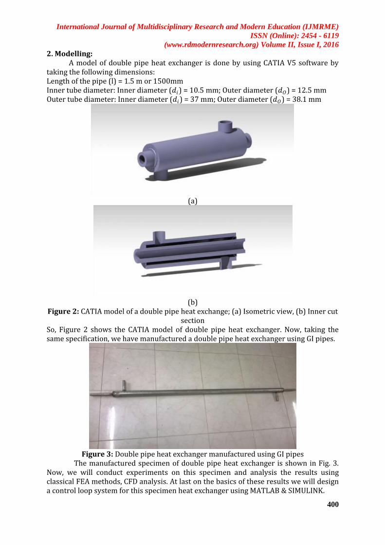
2. Modelling: A model of double pipe heat exchanger is done by using CATIA V5 software by taking the following dimensions: Length of the pipe (l) = 1.5 m or 1500mm Inner tube diameter: Inner diameter (𝑑𝑖) = 10.5 mm; Outer diameter (𝑑𝑂) = 12.5 mm Outer tube diameter: Inner diameter (𝑑𝑖) = 37 mm; Outer diameter (𝑑𝑂) = 38.1 mm
(a)
(b)
Figure 2: CATIA model of a double pipe heat exchange; (a) Isometric view, (b) Inner cut section
So, Figure 2 shows the CATIA model of double pipe heat exchanger. Now, taking the same specification, we have manufactured a double pipe heat exchanger using GI pipes.
Figure 3: Double pipe heat exchanger manufactured using GI pipes
The manufactured specimen of double pipe heat exchanger is shown in Fig. 3. Now, we will conduct experiments on this specimen and analysis the results using classical FEA methods, CFD analysis. At last on the basics of these results we will design a control loop system for this specimen heat exchanger using MATLAB & SIMULINK.

International Journal of Multidisciplinary Research and Modern Education (IJMRME)
ISSN (Online): 2454 - 6119
(www.rdmodernresearch.org) Volume II, Issue I, 2016
401
Figure 4: Schematic diagram of the control loop system
Above Figure 4 Shows the schematic diagram of the control loop system of how the control valves and heat exchanger will be connected and how the solenoid control valve will control the outlet flow of milk by using Arduino microcontroller and temperature sensor. 3. Classical Analyses: Experiments have been conducted on the manufactured heat exchanger and test values of Counter flow have been recorded for analysis purpose. Hot water has been used for outer tube fluid to heat the milk in inner tube. The test values are given in the table below:
Table 1: Test values of Counter flow
Milk Water
Time taken for filling 1 litre tank
(sec.)
Inlet temp Outlet temp (℃) ( ℃)
Time taken for filling 1 litre tank
(sec.)
Inlet temp Outlet temp (℃) ( ℃)
65 36 68 18 76 70
63 36 66 15 75 69
60 35 67 19 78 71
64 37 75 17 86 81
Above Table.1 shows the test vales of the experiments. Now, taking the last column values we can do classical analysis by using some formulae. We have taken: Specific Heat of Water (𝐶𝑝𝑤 ) = 4.187 KJ/Kg K; Specific Heat of Milk (𝐶𝑝𝑚 ) = 3.93 KJ/Kg K
Density of Water (𝜌𝑤 ) = 1000 kg/𝑚3; Density of Milk (𝜌𝑚 ) = 1035 kg/𝑚3 Area of Inner tube:𝐴𝑖 = 𝜋 × 𝑑𝑖 × 𝑙 = 𝜋 ×10.5× 10−3 ×1.5 = 0.049 𝑚2 (1a) 𝐴𝑂 = 𝜋 × 𝑑𝑂 × 𝑙 = 𝜋 ×12.5× 10−3 ×1.5 = 0.059 𝑚2 (1b)
Mass flow rate of cold liquid, 𝑚𝑐 = 𝜌×𝑣
𝑡 =
1035×10×10−6
64×10 = 1.61× 10⁻⁵ kg/hr (2a)
Mass flow rate of hot liquid, 𝑚 = 𝜌×𝑣
𝑡 =
1000×10×10−6
17×10 = 5.88× 10⁻⁵ kg/hr (2b)
Now, by using the values from equation (2a) & (2b) we get, Heat transfer rate for Cold fluid, 𝑄𝑐 = 𝑚𝑐 × 𝐶𝑝𝑐 ×(𝑇𝐶𝑂 − 𝑇𝐶𝑖)
= 1.61× 10−5 × 3.93 ×(75-37) = 2.4× 10⁻³ KJ/hr (3a)
International Journal of Multidisciplinary Research and Modern Education (IJMRME)
ISSN (Online): 2454 - 6119
(www.rdmodernresearch.org) Volume II, Issue I, 2016
402
Heat transfer rate for hot fluid, 𝑄 = 𝑚 × 𝐶𝑝 ×(𝑇𝑖 − 𝑇𝑜)
= 5.88× 10−5 × 4.18 ×(86-81) = 1.23× 10⁻³ KJ/hr (3b) Logarithmic Method (LMTD) For Counter Flow:
LMTD (∆𝑇𝑚 ) = 𝑇𝑖−𝑇𝐶𝑖 −(𝑇𝑜−𝑇𝐶𝑖 )
ln [(𝑇𝑖−𝑇𝐶𝑂 )/(𝑇𝑜−𝑇𝐶𝑖 )] =
86−37 −(81−37)
ln[(86−75)
(81−37)]
= 8.25 (4)
Now, by using the values of equation (3a) & (3b) we can get,
𝑄𝑎𝑣𝑔 = 𝑄+𝑄𝐶
2 =
(2.4+1.23)×10−3
2= 1.815× 10⁻³ KJ/hr (5)
So, Overall Heat transfer coefficient, U can be determined using following formula Q = U×A ×(∆𝑇𝑚 ) By using the values of equations (1a), (1b), (4) & (5) we can calculate
𝑈𝑖 (Based on𝐴𝑖) =1.815×10⁻³
0.049×8.25≈ 4.49× 10⁻³ w/𝑚2k
And 𝑈𝑂 (based on𝐴𝑂) = 1.815×10⁻³
0.059×8.25= 3.73× 10⁻³ w/𝑚2k
At last, Effectiveness of the Heat Exchanger, € =𝑄𝐶
𝑄 = 1.95
4. CFD Analyses: Above, we can see the classical analyses of the heat exchanger using the
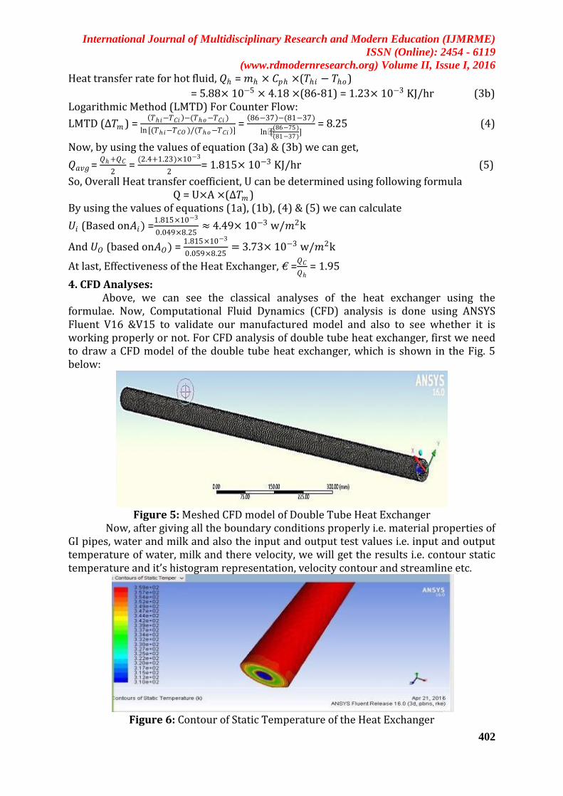
formulae. Now, Computational Fluid Dynamics (CFD) analysis is done using ANSYS Fluent V16 &V15 to validate our manufactured model and also to see whether it is working properly or not. For CFD analysis of double tube heat exchanger, first we need to draw a CFD model of the double tube heat exchanger, which is shown in the Fig. 5 below:
Figure 5: Meshed CFD model of Double Tube Heat Exchanger
Now, after giving all the boundary conditions properly i.e. material properties of GI pipes, water and milk and also the input and output test values i.e. input and output temperature of water, milk and there velocity, we will get the results i.e. contour static temperature and it’s histogram representation, velocity contour and streamline etc.
Figure 6: Contour of Static Temperature of the Heat Exchanger
International Journal of Multidisciplinary Research and Modern Education (IJMRME)
ISSN (Online): 2454 - 6119
(www.rdmodernresearch.org) Volume II, Issue I, 2016
403
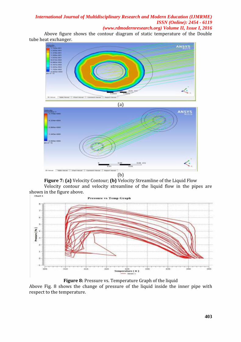
Above figure shows the contour diagram of static temperature of the Double tube heat exchanger.
(a)
(b)
Figure 7: (a) Velocity Contour; (b) Velocity Streamline of the Liquid Flow Velocity contour and velocity streamline of the liquid flow in the pipes are shown in the figure above.
Figure 8: Pressure vs. Temperature Graph of the liquid
Above Fig. 8 shows the change of pressure of the liquid inside the inner pipe with respect to the temperature.

International Journal of Multidisciplinary Research and Modern Education (IJMRME)
ISSN (Online): 2454 - 6119
(www.rdmodernresearch.org) Volume II, Issue I, 2016
404
(a)
(b)
Figure 9: Histogram (a) the Static Temperature change ;(b) Velocity magnitude In Fig. 9, two histograms have shown representing the static temperature change and velocity magnitude of liquid flow outlet. 5. SIMULINK Model and Calculation:
Consider the heat exchange process shown in Fig. 10. Suppose that you can adjust the inlet liquid rate (𝑤𝑖 ) and temperature (𝑇𝑖) of the inner pipe, and the temperature of outer pipe (𝑇𝑆) independently. The liquid outlet temperature (𝑇𝑂) and flow rate (𝑤 𝑂), and the heat transfer rate (𝑞 ) vary accordingly. [6]
Figure 10: Heat Exchange process [6]

International Journal of Multidisciplinary Research and Modern Education (IJMRME)
ISSN (Online): 2454 - 6119
(www.rdmodernresearch.org) Volume II, Issue I, 2016
405
Now, using background from previous courses (and a few additional assumptions), we can obtain the following model equations: 𝑤𝑖 = 𝑤𝑂 = 𝑤 (assumption)& Heat Transfer rate: 𝑞 = UA (𝑇𝑆 − 𝑇𝑂) (6)
Heat Energy Balance: w𝐶𝑝𝑑𝑇𝑂
𝑑𝑡 = 𝑤 𝐶𝑝 (𝑇𝑖 − 𝑇𝑂) + 𝑞
= 𝑤 𝐶𝑝 (𝑇𝑖 − 𝑇𝑂) + UA (𝑇𝑆 − 𝑇𝑂) from (6) (7)
Where, 𝑤 = mass rate of liquid entering and leaving the tubes, kg/sec 𝑞 = rate of heat transfer to the liquid in the tubes, kW w = mass of liquid in the tubes =(ρ
𝐿𝑣𝑙) kg
UA = product of overall heat transfer coefficient and tube surface area, kW/K 𝑇𝑆 = outer pipe liquid temperature, °𝐶 𝑇𝑖 , 𝑇𝑂= temperature of liquid entering and leaving tubes, °𝐶 𝐶𝑝 = specific heat of liquid at constant pressure, kJ/kg-K
Now, the assumption made can be ignored. Here, 𝑤, 𝑇𝑖 , 𝑇𝑆 are independent variables i.e. they are inputs. But 𝑞 and 𝑇𝑂 are dependent variable i.e. they are outputs.So, now using these equations (6) & (7), we can design a Simulink model of heat exchanger and by putting our test values as input, we will get the output results.
(a)
(b)
Figure 11: SIMULINK Model (a) Heat transfer rate, (b) Heat energy balance By using Heat transfer rate equation (6) and Heat energy balance equation (7), we can design the above both models in SIMULINK. Now, using both as subsystems we can model a heat exchanger shown in below Fig. 12

International Journal of Multidisciplinary Research and Modern Education (IJMRME)
ISSN (Online): 2454 - 6119
(www.rdmodernresearch.org) Volume II, Issue I, 2016
406
Figure 12: Heat Exchanger SIMULINK model using subsystems
Now, we need to design the control loop system of this heat exchanger. So, in this section the heat exchanger system, actuator, valve, sensor are mathematically modelled using the available experimental data.[5] The experimental process data’s are summarized below: Exchanger response to the liquid flow gain: 16°𝐶/kg/sec Time constants: 30 sec Exchanger response to variation of process fluid flow gain: 1°𝐶/kg/sec Exchanger response to variation of process temperature gain: 3°𝐶/°𝐶 Control valve pressure capacity for liquid: 3 bar Time constant of control valve : 3 sec The range of temperature sensor: 36°𝐶 to 100 °𝐶 Time constant of temperature sensor: 10 sec Process transformation function: 30s+1 Valve function: 3s+1 Distortion function: 30s+1 Sensor function: 10s+1 Drive rate: 0.75 Laplace domain variable is denoted by ‘s’
Now, Feed forward transformation function: 𝐺𝐶𝑓(𝑠)= 𝐺𝑑 (𝑠)
𝐺𝑝 (𝑠)
Where, 𝐺𝑝(𝑠) = process transformation function
And 𝐺𝑑(𝑠)= distortion transformation function both are inputs From the experimental data, transfer functions and the gains are obtained as below:
Transfer function of process: 16
30s+1
Gain of valve: 0.133
Transfer function of valve: 0.009975
30s+1
Gain of current to pressure converter: 0.75 Transfer function of disturbance variables:
(i) Flow: 1
30s+1 (dominant). (ii) Temperature:
3
30s+1

International Journal of Multidisciplinary Research and Modern Education (IJMRME)
ISSN (Online): 2454 - 6119
(www.rdmodernresearch.org) Volume II, Issue I, 2016
407
Transfer function of sensor: 0.16
10𝑠+1
Now, by using all these functions and values we can design a SIMULINK model of control loop system of the heat exchanger using a PID controller.
Figure 13: PID controlling SIMULINK model with feed-forward controller
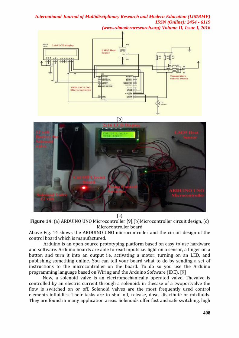
Above SIMULINK model shown in Fig. 13 can be used as a control loop having PID controller and a feed-forward function. 6. Experimental Work: Now, using above SIMULINK models, a real time control system is created by using ARDUINO UNO microcontroller. In this control system, an ARDUINO UNO microcontroller is used to control the outlet valve of the inner pipe in the Heat exchanger which is a 12volt solenoid valve. As a temperature sensor, LM35 heat sensor is used. The solenoid valve is connected to a 12 volt battery for run. A 12 volt 1 amp AC to DC adapter is used to run the whole ARDUINO microcontroller board, shown in bellow Fig. 14
(a)
International Journal of Multidisciplinary Research and Modern Education (IJMRME)
ISSN (Online): 2454 - 6119
(www.rdmodernresearch.org) Volume II, Issue I, 2016
408
(b)
(c)
Figure 14: (a) ARDUINO UNO Microcontroller [9],(b)Microcontroller circuit design, (c) Microcontroller board
Above Fig. 14 shows the ARDUINO UNO microcontroller and the circuit design of the control board which is manufactured.
Arduino is an open-source prototyping platform based on easy-to-use hardware and software. Arduino boards are able to read inputs i.e. light on a sensor, a finger on a button and turn it into an output i.e. activating a motor, turning on an LED, and publishing something online. You can tell your board what to do by sending a set of instructions to the microcontroller on the board. To do so you use the Arduino programming language based on Wiring and the Arduino Software (IDE). [9] Now, a solenoid valve is an electromechanically operated valve. Thevalve is controlled by an electric current through a solenoid: in thecase of a twoportvalve the flow is switched on or off. Solenoid valves are the most frequently used control elements influidics. Their tasks are to shut off, release, dose, distribute or mixfluids. They are found in many application areas. Solenoids offer fast and safe switching, high

International Journal of Multidisciplinary Research and Modern Education (IJMRME)
ISSN (Online): 2454 - 6119
(www.rdmodernresearch.org) Volume II, Issue I, 2016
409
reliability,long service life, good medium compatibility of the materials used, low control power and compact design. [9] Here, in this project work Arduino is used to control the 2 way solenoid valve by sending and cutting off electric current according to the feedback temperature sent by LM35 heat sensor. Now, the working of the Arduino microcontroller board is shown in the figures below:
(a)
(b)
Figure 15: (a) Solenoid Valve Closed, (b) Solenoid Valve Open The working of the microcontroller board is very easy to run and understand i.e. the outlet milk temperature should be minimum 72℃. So, we set the cut off temperature as 72℃. But we can see in Fig.15 (a) the real time temperature is different. It may be normal room temperature below than 72℃ or higher than that i.e. in this case its 80℃. So, the LM35 sensor senses the real time temperature and sends the feedback signal to the Arduino Uno microcontroller. Hence the power is switched ON as the greed LED is on sending electric current to the solenoid valve and keeping it close. But in Fig. 15(b), we can see the real time temperature came down the cut off temperature i.e. 62℃. Now, the microcontroller sends signal to the cut off circuit and the electric current is cut off from the solenoid valve causing it open and inlet milk can come out at required temperature which is 72℃. Thus the whole control system works. 7. Results and Discussion: The results are obtained from the output of the SIMULINK model of the heat exchanger already designed. As a input we gave the test values of counter flow

International Journal of Multidisciplinary Research and Modern Education (IJMRME)
ISSN (Online): 2454 - 6119
(www.rdmodernresearch.org) Volume II, Issue I, 2016
410
experiment and as a output we can see how the heat exchanger behaving depending upon the given inputs as well as the control loop system. Now the given inputs are: 𝑤 =16.1kg/sec, UA = 24.5 kW/K, 𝑇𝑆 =86°𝐶, 𝑇𝑖=37°𝐶, 𝐶𝑝 = 3.93 kJ/kg-K
(a)
(b)
Figure 16: Outlet temperature 𝑻𝑂 response scope, (a) initial stage, (b) at 10 sec Now, in Fig.16 we can see the change in outlet temperature of inner pipe with respect of time i.e. 𝑇𝑂 response scope. In Fig16 (a) it’s the initial stage and in Fig. 16(b) it’s after 10 sec. By comparing them we can see the temperature varies with respect to time.
(a)

International Journal of Multidisciplinary Research and Modern Education (IJMRME)
ISSN (Online): 2454 - 6119
(www.rdmodernresearch.org) Volume II, Issue I, 2016
411
(b)
Figure 17: Heat transfer rate 𝒒 response scope, (a) initial stage,(b) after 10 sec Again, in Fig.17 we can see the change in Heat transfer rate with respect of time i.e. 𝑞 response scope. In Fig16 (a) it’s the initial stage and in Fig. 16(b) it’s after 10 sec. 8. Conclusions
The paper presented a design of control loop system to control the outlet temperature of a double pipe heat exchanger which can be applied in Milk process plant to heat milk at desired temperature i.e. 72℃ . Here, we also have done classical analysis using formulae and CFD analysis using ANSYS. From these analyses we can understand the behaviour of the heat exchanger. Then we modelled Heat exchanger and control loop system in SIMULINK model by using MATLAB. The working and behaviour of the control system were identified. The main objective of this paper was to design and manufacture a control system to get required temperature which is achieved i.e. a double pipe heat exchanger and a control loop system using Arduino microcontroller is manufactured and found that it is working perfectly as expected from the output results.
Figure 18: Arduino Microcontroller attached with the Heat exchanger
Now, in Fig. 18 we can see the Arduino microcontroller is attached with the heat exchanger. The heat exchanger is coated with heat insulation thermal foam tape for better performance and safety of the user. The 2 inlets and 2 outlet ports are connected with hose pipe and clamped. The LM35 heat sensor is inserted in the inner pipe outlet which is connected with the solenoid valve as shown in figure above. Again, the outlet of
International Journal of Multidisciplinary Research and Modern Education (IJMRME)
ISSN (Online): 2454 - 6119
(www.rdmodernresearch.org) Volume II, Issue I, 2016
412
the solenoid valve is connected with hose pipe. So, this is the finished setup of this project work. References: 1. P.C. Mukeshkumar, J. Kumar, S. Suresh, K. Praveen babu, “ Experimental study on
parallel and counter flow configuration of a shell and helically coiled tube heat exchanger using Al2O3 / water Nano fluid”, J. Mater. Environ. Sci. 3, Volume 4, page Number 766-775, 2012
2. Mohammed Rabeeh V, Vysakh S, “Design of Shell and Tube Heat Exchanger Using MATLAB and Finding the Steady State Time Using Energy Balance Equation”,International Journal of Advanced Mechanical Engineering, Volume 4, Number 1, Page Number 95-100, 2014
3. A.GopiChand, A. V. N. L. Sharma, G. Vijay Kumar, A.Srividya,“ Thermal Analysis Of Shell & Tube Heat Exchanger Using MATLAB and FLOEFD Software”, International Journal of Research in Engineering and Technology, Volume 1, Issue 3, Page Number 276-281, Nov-2012
4. Paresh Patel, Amitesh paul, “Thermal Analysis Of Tubular Heat Exchanger By Using Ansys”, International Journal of Engineering Research & Technology, Volume 1, Issue 8, Page Number 1-8, Oct-2012
5. NeerajSrivastava, Deoraj Kumar Tanti, MdAkram Ahmad, “Matlab simulation of temperature control of heat exchanger using different controllers”, Automation, Control and Intelligent Systems, Volume 2, Number 1, Page Number 1-5, March 10, 2014
6. N. L. Ricker, “ A Simulink Tutorial”, ChemE 480, Page Number 1-21 7. Food- a fact of life, “Pasteurisation, sterilisation and irradiation”,2009,
www.nutrition.org.uk, www.foodafactoflife.org.uk 8. W. Durfee, “Arduino Microcontroller Guide”, University of Minnesota, Version Oct-
2011, www.me.umn.edu/courses/me2011/arduino/ 9. Wikipedia-the free encyclopedia, https://en.wikipedia.org/wiki/ 10. Temperature Control in a Heat Exchanger MATLAB& Simulink Example
MathWorksIndia,http://in.mathworks.com/help/control/examples/