design of an inwheel motor
TRANSCRIPT

8/3/2019 Design of an Inwheel Motor
http://slidepdf.com/reader/full/design-of-an-inwheel-motor 1/7
Design of an in-w eel motorf er
electric vehicle
H.C. ovattV.S. RamsdenB.C. Mecrow
Indexing terms: Solar power, Electric vehicles, In-wheel electric motor
Abstract:The design of an in-wheel electric motor
for the solar-powered vehicle ‘Aurora’, entered in
the 1996, 3010km Darwin ~ Adelaide World
Solar Challenge solar car race is described.
Compared to other entrants in the race, the
brushless DC motor is more efficient (97.5%
compared to 92-95%) and lighter (8.3kg
compared to 12-16kg) than all other direct-drive
motors, and more efficient than all motodgearcombinations. This is achieved by the use of high
flux-density rare-earth magnets, and computer
aided optimisation of an axial-flux configuration
consisting of a Halbach magnet array and an
ironless air-gap winding.
Lis t of symbols
B = magnetic flux density
R = radius
p = resistivity
h = length
w = electrical frequency, radls
n = speed, radls
1 Introduction
The Darwin - Adelaide World Solar Challenge solar
car race provides an ideal platform fo r the development
of new high efficiency electric drives. There is very high
expenditure on maximising the efficiency of the power
generated by the solar cells, and minimising the aerody-
namic, mechanical and electrical losses in the car. For a
race car to remain competitive, its electric drive must
also combine exceptionally high efficiency with low
mass. The cost of the drive motor is a relatively small
component of the overall race car cost, so that finan-
cial constraints do not significantly affect the design.
0 EE, 1998
IEE Proceedings online no. 19982167
Paper received 18th March 1998
H.C. Lovatt is with CSIRO Telecommunications and Industrial Physics,PO Box 128, Lindfkld, NSW 2070, Austrralia
V.S. Ramsden is with the Faculty of Engineering, University of Technol-ogy, Sydney, PO Box 123, Broadway, NSW 2007, Australia
B.C. Mecrow is with the Department of Electrical and Electronic Engi-neering, University of Newcastle upon Tyne, NE1 7RU, UK
To win the race a car needs to convert the maximum
amount of solar energy, and use this energy well. The
solar cell efficiency (24% from the University of New
South Wales) and the race rules limit the available
power to about 1.8kW for a single-seater car. A well
designed solar powered race car can potentially average
l00kdh at 1.8kW. In contrast, a typical road car,
driven at this speed by an internal combustion engine,
uses about 35kW from the engine and about 140kW
from the fuel.The losses incurred in mechanical gearing are exces-
sively high, so direct drives have become the preferred
alternative. These were first used in the World Solar
Challenge in 1993 by three teams: Honda, Engineering
College of Biel, and Northern Territory University El]).
Several other teams followed in 1996 [2]. The Aurora
Vehicle Association introduced a novel ‘wing section’
car shape in 1993, which required a single front wheel
and two rear wheels, rather than the more common
reverse configuration with two wheels at the front [3] .
Most of the 1.8kW generated in the solar car is used
in overcoming aerodynamic drag and rolling resistance,
with typically 5-10% lost in the electrical drive system.
If the electrical losses were to be reduced to 2-3% it
would give a key advantage in the race. This provided
the motivation for the present work: design and testresults of a very efficient, light-weight, direct-drive, in-
wheel motor, ultimately placed in the single front wheel
of the Aurora solar car are presented (Fig. 1) . The effi-
ciency of the motor was optimised, incorporating a
mass penalty to allow for tyre rolling resistance. Cost
was not considered in the design.
Fig.1 Aurora solav CUT
2 Specification
The specification was initially for two motors, mounted
in the rear wheels, with no fixed limit on overall mass.
Direct drive was required to eliminate drive-train losses
and each motor wa s required to fit inside a wheel to
IEE Proc -Electr POWWA p p l , Vol 145, No 5, September 199802

8/3/2019 Design of an Inwheel Motor
http://slidepdf.com/reader/full/design-of-an-inwheel-motor 2/7
reduce aerodynamic drag and maximise efficiency.
However, initial work revealed that the complete speci-
fication could be met with a single motor of no more
than six kilograms active mass. This motor was esti-
mated to have full load losses of less than 56W, giving
an efficiency of over 97%. This produced a much sim-
pler, lighter system than a two motor drive, and
became the preferred option. The motor could fit in the
front wheel, allowing simple steering without upsetting
the car stability at high speed. Based around this pre-
liminary work a detailed specification was created, and
is summarised in Table 1.
Table 1: Specification
Continuous output power 1800W
Peak power for 72s (hil l climb)
Mean speed at 100, km/h
Max. speed at 130, km/h
Continuous torq ue 16.2"
Peak torque ( hill climb) 50.2 Nm
Starting torq ue 50.2 Nm
Maxim um outside diameter 360"
Max imu m axial length 43"
Mass penalty 0.75W/kg
3.1 x 1800W
1060 rev/ min
1380 rev/min
Max imu m active mass 6 kg
Note that there were two factors associated with
wheel mass: the first was a maximum value beyond
which stability of the car is compromised, with the
front wheel starting to lift on rough roads at high
speed. The second factor was a penalty with regard to
increased rolling resistance and reduced acceleration as
the mass increases. This latter penalty was expressed as
an effective loss per kilogram of additional mass, but
was only 0.75Wlkg. Thus, even at the maximum mass
of 6.0kg it remained a rather small penalty function in
the overall design.
The specification called for a continuous torque per
unit active mass of at least 3.24Nm/kg, which was
more than double the value previously achieved by theother direct-drive motors used in the solar-powered
race. It was also more than double the torque density
achieved by a typical induction motor of similar rating
(but of much lower efficiency). The torque per unit vol-
ume had to exceed 3700Nm/m3, which was an equally
high requirement.
Efficiency had to be maximised throughout the speed
and power range, so that the car was able to continue
to perform well under all conditions. This required
minimisation of all load-independent losses, in order to
maintain efficiency even in cloudy conditions, when the
power generated was substantially reduced.
3 Machine type
Permanent magnet machines give a combination ofhigh torque density and high efficiency because a high
electric loading can be obtained, and no magnetising
current losses are incurred. Thus they became the main
contenders for this application. Inability to control the
field flux meant that iron losses could not be reduced
at light load. It was therefore important to produce a
design with low hysteresis and eddy current loss to
maintain efficiency across the power range.
The available envelope within the front wheel had a
IE E Pror. -Elertr. Power Appl . , Vol. 145, No . 5 , September 1998
relatively large diameter, with a short axial length of
only 12% of the diameter. The available space could
contain a machine of well over 6.0kg, so that only i1
portion of the volume was to be actively used. How-
ever, it remained desirable to continue to use the maxi-
mum available radius, so that the magnetic forces were
acting at a large radius, thus giving the maximum
torque per unit mass. Consequently, the machine struc-
ture was chosen to form a ring, with a hole at the cen-
tre. This structure is commonly encountered in large,
high torque machines, when inertia is not a significant
problem.
3. I Pole numberThe choice of pole number was particularly important
in this machine design. A high pole number was desira-
ble for the following reasons:
A large proportion of a typical machine mass com-
prises the flux return path. This mass is inversely pro-
portional to the pole number.
A high pole number was required to reduce the end-
winding length and space. This was especially impor-
tant when the machine had a relatively short stack
length. It can easily be shown that with less than 30
poles in this machine the endwinding length was much
greater than the active length, thus imposing a loweir
limit on the pole number.
These arguments must be balanced against the fol-
lowing issues which become important as the pole
number (and therefore electrical frequency) rises:
.
There is an increase in iron losses in all stationary
iron components.
There is a rise in eddy current losses in any air-gap
windings.
For a given air-gap length the magnet pole-pole
leakage fields rise.
There is an increase in the converter switching fie,-
quency, ,and therefore a reduction in converter effi-
ciency.
From a practical viewpoint, it should also be noted
that as the pole number rose, the dimensions of each
pole reduced, so that the machine was composed ofmore small components and became difficult to assem-
ble. A 60-pole design had a pole pitch of the order of14" and a maximum electrical frequency of 690Hz.
This electrilcal frequency was found to impose a maxi-
mum limit on the possible pole number.
3.2 Machine geometryRadial designs: In order to ascertain whether a radial
field machine was feasible it was necessary to consider
the endwinding space required. At the maximum of 60
poles, the pole pitch was approximately 14mm, and a
similar amount of space was required at each end of
the machine to accommodate the axial portion of the
endwinding. The total available axial space was 43mm,thus leaving only 15" for the active length. This
length was too short for a competitive design, so that
the radial field machine was abandoned.
Axial designs: There were a number of possibilities for
an axial field design. Some designs [4, 51 had a singlerotor and stator. However, such designs had several
thousand newtons of axial pull on the bearings and
were not favoured. If the axial forces were to be bal-
anced, then either a single rotor, sandwiched between
403
8/3/2019 Design of an Inwheel Motor
http://slidepdf.com/reader/full/design-of-an-inwheel-motor 3/7
two stators, or a single stator, sandwiched between two
rotors was required [6]. The double stator option
required more stationary iron than the double rotor
one, and thus had greater iron loss. The double rotor
design was therefore chosen. This design also had sev-
eral mechanical advantages, as it became possible to
mount each of the two rotors on the side walls of the
wheel.
The pros and cons of an air-gap winding are rela-
tively complex. In general terms an air-gap winding
had the following advantages:For a given depth of slot there was more space avail-
able for the winding;
A toothed structure was likely to have high tooth
flux densities, and therefore a relatively high iron
loss;
For a given set of loadings the mass was reduced if
there were no teeth present;
A toothed structure was difficult to laminate in an
axial field machine.
However, there were the following disadvantages:
A poorer thermal performance when the winding
was deep;
A lower flux density for a given depth of magnets;
Significant winding eddy current loss.
Optimisation of toothed structures revealed a rather
large mass of teeth and a large iron loss. Unless the
machine was constructed with a glassy metal core [7],
the losses were calculated to exceed 80W in total. It
was also found that with special magnet arrangements
in an air-gap winding design it was possible to achieve
peak air-gap flux densities of over 0.8T. This was ashigh as that typically achieved with a toothed structure,
so that an air-gap winding became the preferred choice,
providing that the thermal performance was adequate
and the eddy current loss was kept low. Work pro-
ceeded with an air-gap winding design.
Even with an air-gap winding design there were two
choices:
(i) A winding wound toroidally round a laminated
core, with all air-gap fields returning circumferentially
through the core [8-lo].
(ii) An ironless stator with all flux passing axially
through the stator (the brushless analogue of the disc
armature DC motor).
The toroidal core machine had the advantages of
high winding utilisation (the endwindings were short)
and a relatively strong mechanical structure. However,
the mass of the iron core was substantial and core iron
loss significant. Optimisation of this design indicated
that a 60-pole machine with a mass of 6.0kg, contain-
ing a glassy metal core, would have a core mass of
about 1.2kg and a core loss of about 2.6W.
The ironless stator machine was predicted to have asimilar performance to the glassy metal machine.
Although construction of the stator winding assembly
was difficult, the ironless stator had the major advan-
tage that there were no forces on the stator during
assembly of the machine. This was particularly impor-
tant, as the stator was likely to be mounted onto a
structure with a poor axial rigidity. Difficulty of assem-
bling and annealing the glassy metal core within the
limited time scale permitted for the project resulted in adecision to adopt the ironless stator topology.
404
In summary, an arrangement featuring axial flux, an
ironless air-gap winding, and outer rotating magnets
was selected for the following reasons.
Ax ia l f l ux was chosen because:
there was inadequate axial length for end windings
in a radial-field air gap winding design;
double magnet rotors could be mounted on the
wheel side walls;
the stator winding could be mounted centrally on the
axle.An air-gap winding was chosen because:
the efficiency with toothed structures was less than
96%, due to tooth iron loss,
a high field was still achievable with new permanent
magnet materials and special magnet arrangements;
more space was available for copper, leading to
lower copper loss;
eddy current loss was controllable with stranded Litz
wire, leading to an efficiency greater than 97%.
An ironless stato r was chosen because:
The performance was similar to that calculated for a
stator with a glassy metal core, which would be diffi-
cult to assemble and anneal;
The mass was minimised for a given air-gap flux;
There were no forces on the stator during assembly;
The thermal performance was adequate.
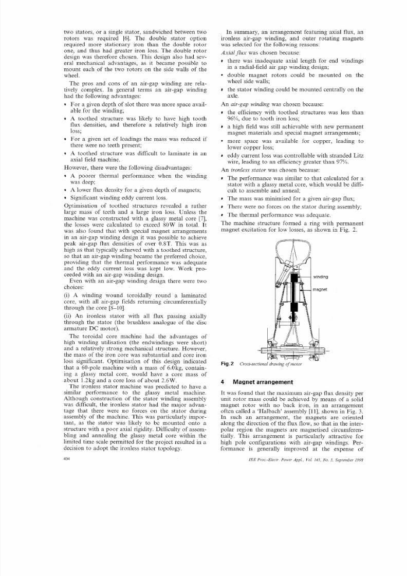
The machine structure formed a ring with permanent
magnet excitation for low losses, as shown in Fig. 2.
-
Fig.2 Cross-sectional drawing o motor
4 Magnet arrangement
It was found that the maximum air-gap flux density per
unit rotor mass could be achieved by means of a solid
magnet rotor with no back iron, in an arrangement
often called a ‘Halbach’ assembly [ll] , shown in Fig. 3.
In such an arrangement, the magnets are oriented
along the direction of the flux flow, so that in the inter-
polar region the magnets are magnetised circumferen-
tially. This arrangement is particularly
high pole configurations with air-gap
formance is generally improved at the expense of
IEE Proc -Electr Power Appl , Vol 145, N o 5, September 1998

8/3/2019 Design of an Inwheel Motor
http://slidepdf.com/reader/full/design-of-an-inwheel-motor 4/7
increased magnet volume and cost. Optimisation pre-
dicted that a design with the Halbach magnet arrange-
ment would have approximately 1OW (20%) less loss
than an equivalent conventional arrangement of the
same total mass, with magnets on backing iron.
t - ~ ~ - ; P
I winding
In the ideal case the orientation of the magnets
changes continuously with position, but in practice a
finite number of magnets per pole must be used. The
design chosen was found to give very good perform-
ance with four magnets per pole. When more magnets
were used, only marginal increase in performance was
possible. The angle of magnetisation of each magnet
was varied, and optimised using search routines embed-
ded in the finite element analysis. Best performance
was produced with magnets at angles of 30" and 60"with respect to the axial direction.
5 Sources of loss
In the chosen motor design the only sources of loss are:
winding copper loss,
9 eddy current loss in the winding,
windage loss,
bearing loss.
Copper loss was the dominant source of loss in the
three phase, fully pitched air-gap winding. The torque
produced for a given excitation current was calculated
using a virtual displacement method within the finite
element simulation. From knowledge of the rated
torque, the required MMF magnitude and resulting
copper loss was determined.The loss Pe resulting from eddy currents in a round
conductor of radius R, resistivity p, and length A,
placed in a pulsating magnetic field of peak flux den-
sity B and frequency w s [I21
(1)- irB2w2 4
P, =8P
It was assumed that eddy current loss only occurs in
the active portion of the winding. To reduce eddy loss,
the winding was made of Litz wire with twisted (trans-
posed) strands to reduce circulating currents.
The internal windage was also calculated from an
analytical formula, which determines from the Taylor
number that fo r this machine the flow regime is lami-
nar with vortices. External windage was assumed to bethe same as for a wheel without the motor, and so was
not included. As there were no axial forces, bearing
losses were also assumed to be the same as for a wheel
by itself; these were not included either.
6 Design optimisation
The design was optimised to minimise the total loss.
The optimisation initially used lumped parameter mod-
I E E P r o < - E l a i r Power A p p l , Vol 145, N o 5, eptember 1998
els, and later used 2-D finite-element analysis. The fol-
lowing assumptions were made:
The heat transfer coefficient between the winding
and the surrounding air was 20Wm-*K-';
Cooling 'was neglected for peak torque heating;
There was no significant radial variation of magnetic;
field in the winding, i.e. no end effects. A 3-D finite-ele-
ment solution indicated that this would not cause
major errors;
The air-gap magnetic field was effectively sinusoidal.
This was confirmed by EMF measurement and fluxdensity calculation.
The mass penalty of 0.75W kg-' was incorporated into
the optimisation process.
6oI
I30 50 60 70
no. of poles
O+ ;
Fig.4 Effect of numbev ofpoles
6.1 Choice of pole numberAs discussed above, between 30 and 60 poles was ini-
tially thought to be sensible for this machine design.
Optimisation results shown in Fig. 4 suggested that
there was a small reduction in total loss penalty as thle
pole number was reduced from 60 to 40 poles, due to ;a
reduction in eddy current loss, but that any further
reduction caused a substantial increase in total penalty.
This arises due to the increasing size of the endwind-
ings and flux return paths. A 40-pole design has a pole
pitch of the order of 21" and a maximum electricad
frequency of 460Hz, both of which are suitable values.
n
c
o c : I3 4 5 6 7 8 9 10 11
active mass,kg
Fig.5 Effect of active mass
6.2 Effect of massFig. 5 shows how the total loss penalty is influenced by
machine mass, with the machine fixed at 40 poles. It
became clear that within the permissible mass range,
any increase in mass resulted in a net gain, despite the
mass penalty of 0.75W/kg. Thus it became clear that
the optimal design would sit at the the upper limit of
mass, in this case 6.0kg.
6.3 Effect of air-gap lengthThe effect of air-gap length is shown in Fig. 6.Although the loss penalty could be reduced by up to5 W with an air-gap length below 2.0mm, the gap was
4105

8/3/2019 Design of an Inwheel Motor
http://slidepdf.com/reader/full/design-of-an-inwheel-motor 5/7
kept a t 2.0mm on each side of the winding to allow for
winding encapsulation and mechanical clearance.
torque constant, no-load losses, load losses, efficiency
and temperature rise.ss1 1.5 2 2.5 3 3.5
air gap length, mm
Fig 6 EfSeectof air-gap length
7 Design results
Some further design results obtained for the 6.0kg
motor are shown in Tables 2 and 3. The magnet
selected was VAC362HR, a neodymium iron boron
material, with B, = 1.33T at 20°C.
Fig.7 Magnet ringTable 2: Design results
Mass of copper 1. 2k g
Mass of magnets 4.78kg
Total active mass 5.98kg
Peak air-gap flux density (20°C)
Winding 2-layer, full y pitched
RMS current density 3.12A/mmz
Total force of attraction on r otor faces
Mass penalty 4.5w
0.91T
4900N
Table 3: Comparison of design and measured results for
6kg motor at 16.2Nm, 1060 rev/min, 1800W, 20°C
Design Motor 2
Axial gap between magnet rotors, mm 9.3 10.0
Phase resistance, Q 0.0723 0.0997
RMS fundamental phase current, A 9.6 11.34
LN RMS EMF, V 61.9 54.3
EMF constan t (LN RMS EMFispeed, radis) 0.56 0.47
Torque constant per phase, Nm/A 0.56 0.49
Copper loss, W 20.0 38.6
Eddy current loss, W 4.6 2.7
Windage (design for 2 mm gap each 0.4 2.1
side), W
Total loss, W
Efficiency (% )
Temperature rise, K
25.0 43.4
98.6 97.9
10.2 18.3
Temp. rise after a further 72 s at 50Nm, 37.5 42
K
Temperature rise at 30Nm, K 30.0 60
Two motors were fabricated. A magnet ring is shownin Fig. 7 and a stator winding in Fig. 8. The stator was
naturally air cooled. The final total weight was 8.3 kg
including magnet carriers. sta tor encapsulation, central
support and terminations.
8 Experimental results
Tests were conducted to determine the motor resist-
ance, inductance, EMF constant, EMF waveform,
Fig.8 Stator winding
8. No-load testsThe no-load losses were separated by a series of retar-
dation tests, as follows:
(1) with the magnets and stator removed to reveal bear-
ing loss and external windage;
(ii) with dummy magnets and the stator inserted to give
the internal windage;
(iii) with the actual magnets replaced, thus adding the
winding eddy current loss.
The results are shown below and graphed in Fig. 9:
External windage = 1.25 x 10⁻⁵n3W
Bearing loss = 0.002~2+ 0.00033n2W
Internal windage = 1.5 x W
Winding eddy loss = 0.00022n2 W
It can be seen that the major no-load loss is the exter-
nal windage (17W a t nominal speed 1060 rev/min), fol-
lowed by the bearings (5W at nominal speed), both of
which are not included in the motor losses. The inter-
IE E Pro cElec tr . Power AppL, Vol. 145, No . 5, eptember 199806

8/3/2019 Design of an Inwheel Motor
http://slidepdf.com/reader/full/design-of-an-inwheel-motor 6/7
nal windage was 2.1 W and winding eddy loss 2.7W.
The internal windage was more than the estimated
value of 0.4W (for 2mm gap each side) due to winding
encapsulation, and the eddy loss lower than the esti-
mated value of 4.6W, but fortuitously the sum was
approximately as estimated.
-0 500 1000 1500
speed,rev/min
No load loss breakdown r om retardation tests compared with no-ig.9load test as a motora Eddy loss in windingsb Eddy loss plus internal windagec Eddy loss, internal windage plus bearings
d Total loss from retardation tests (Eddy loss, internal windage, bearings plusexternal windage)Total loss from no load motor test
The open circuit line-neutral EMF constant meas-
ured during the third retardation test was 0.47Vl(radl
s), 16% lower than the estimated value of 0.56V/(rad/s).
This indicates a reduced flux linkage, and largely
explains the lower winding eddy loss (proportional to
B2 as shown in eqn. 1). The magnet flux density profile
has not yet been measured to determine the cause of
the flux decrease. But interestingly, it could be meas-
ured in an open motor, as there is no backing iron and
the permeability of the rare earth magnet in the region
of operation is close to 1.0, so the air gap flux density
is the sum of that from the two magnet rings in isola-
tion.
8.2 Load testsLoad tests were conducted by mounting the wheel
between two shaft torque transducers (providing low
friction bearings) and allowing the tyre to rest with the
appropriate force on a rotating flywheel. The flywheel
was then loaded with a DC generator, as shown in
Fig. 10. Depending on the direction of rotation, one
torque transducer output shaft was locked to react
against the wheel motor.
coupling
torque transducernot in use-,
in-wheel motor and tyre
,torque transducer in use
alternate PO
for locking
support for torque/transducer
rolling road (large lywheel)
Fig.10 h a d est rig
IE E Proc -Electr. Power Appl . , Vol. 145,No . 5, eptember 1998
During both load tests and in the actual race, the
motor was supplied from a quasi-square-wave MOS-
FET inverter. The motor synchronous inductance was
only 22pH (0.Olp.u.) so external inductors of 1OOpH
(0.05p.u.) per phase were used to limit the current rip-
ple resulting from the switching action of the converter.
The RMS value of the quasi-square-wave current was
5% higher than the ideal sine wave, leading to 10%extra copper loss (- 4 W), but saving some inverter
switching loss.
Input power, voltage, current and supply frequency
(speed) were measured with a calibrated VoltechPM3000A, 0-500kHz, 0.1% digital power analyser, and
the torque transducers were calibrated Vibrometer TM
series, 0.2%. The resistance was measured with a Crop-
ico digital milliohmmeter.
motor speed,rev/min
Fig.11 Efficiency o motor 2 at various oud torques
Some results for motor 2 are compared with design
values in Table 3 (the corresponding efficiency of
motor 1 was 97.5%), and the efficiency predicted from
the measured results is plotted against speed in Fig. 11,
with 10mQ added to the phase resistance for leads and
connections. The machine has almost 98% efficiency at
rated torque and speed, but the winding resistive loss
reduces the efficiency if this torque is maintained at
lower speeds. At one half rated torque the machine
exceeds 97% efficiency once above one quarter base
speed. The copper loss was higher than expected due tothe lower flux mentioned above, and due to a higher
phase resistance. With more careful construction in
future it should be possible to reduce the copper loss
and approach the estimated efficiency.
Table 4: Comparison of Aurora motor at 30" with
30Nm, 950 rev/min induction motor and internal com-
bustion engine and drive train
Torquehotal Torque/total Efficiency Losses
weight ratio volume ratio
NIm/kg Nm/m3 % %
Aurora 3.61 10135 96 4
Induction 0.80 1500 82 18
IC engine 1.5 1970 25 75
The performance at 30" (the approximate thermal
limit rating with natural cooling) is contrasted with
that of a typical 30Nm, 6-pole induction motor and an
internal combustion engine and drive train in Table 4.
Compared with an induction motor, this machine pro-
duces over four times the torque per unit mass, and six
times the torque per unit volume, with less than one
quarter the losses. An inverter mass and volume should
407

8/3/2019 Design of an Inwheel Motor
http://slidepdf.com/reader/full/design-of-an-inwheel-motor 7/7
r comparison with the
rora performance with 1993
min 4060 1000 900 600
Nominal torque, N m 16.2 14.3 14 9 22.3
Thermal limit torque, Nm 30 14.3 14 9 55.7
Nominal torquehotal 1.95 1.12 1.24 1.35
weight ratio, Nm/kg
Efficiencv (%) 97.5 95 95 92
A further comparison is given in Table 5, with the
earlier direct-drive solar car motors (The efficiency of
the Biel motor is given in [l ] as 97.5 YO t 14.9Nm, 900rev/min (1.4kW), but 1996 information from Storey
gave this as 95%). The new Aurora motor has a lower
inass and higher efficiency than all the other motors.
9 Conclusions
This report has detailed a motor design which has been
optimised for high-efficiency, in-wheel operation. The, air-gap winding in order to
revlmin, with 6.0kg of active
than 91.5 YO .The design
the required rating. This
r a range of applications
st be combined with very
10 Acknowledgments
The authors acknowledge the help and advice in motor
and controlbr design, fabrication and testing given by:
408
J. Dunlop, P. Gwan, and W. Wu at CSIRO; A. Cur-
genven, W. Holliday, and P. Watterson at UTS; G.Wilkinson; and the Aurora team, particularly S. Bick-
nell, M. Burns, G. Locock, and R. Simmonson. Finan-
cial support from CSIRO, UTS and Aurora is
acknowledged.
1 1 References
1
2
3
4
5
6
7
8
9
10
11
12
?TOREY, J.V.W., SCHINCKEL, A.E.T., and KYLE, C. R.:
Solar racing cars 1993 world solar challenge’ (Australian Gov-ernment Publishing Service, Canberra, 1994)
PHRIS, C.P. and GUELDEN, M.R.: ‘Speed of light - the 1996world solar challenge’ (Photovoltaics Special Research Centre,University of New South Wales, Sydney, 1997)
BADDELEY, V., UMPHRIS, C., and PUDNEY , P.: ‘The
Aurora Q1 solar-powered racing car’. Presented at ANZAASCongress, Australia, 1994
‘What’s the Diff? ‘Desert Rose’ solar vehicle hub drive technol-
ogy’, Australian Energy Management News, June 1994,
DI NAPOLI, A., CARICC HI, F., CRESCIMBINI, F., andNOTA, G.: ‘Design criteria of a low-speed, axial flux, PM syn-chronous machine’. Proceedings of international conference on
Evolution and modern aspects of synchronous machines, 1991, Vol.3, pp. 1119-1124
ZHANG, Z., PROFUMO, F., and TENC ONI, A.: ‘Axial-fluxversus radial-flux permanent magnet-motors’, Electromotion,1996, 3, pp. 134-140
JENSEN, C.C., PROFUMA, F., and LIPO, T.A.: ‘A low losspermanent magnet brushless DC motor utilizing tape wound
amorphous iron’, IEEE Trans. Ind. Appl . , 1992, 28, pp. 646-651SPOONER, E., and CHALMERS, B.J.: ‘Toroidally-wound, slot-less, permanent-magnet, brushless DC motors’. Proceedings of
SPOONER, E., and CHALMERS, B.J.: ‘TORUS: a slotless,
toroidal-stator, permanent-magnet generator’, I E E Proc. B, 1992,139, pp. 497-506
CARICCHI, F., CRESCIMBINI, F., HONORA TI, O., DINAPOLI, A., and SANTINI, E. : ‘Compact wheel direct drive forEVS’, IEEE Ind. Appl. Mag . , 1996, pp. 25-32
OFORI-TENKORANG, J., and LANG, J.H.: ‘A comparative
analysis of torque production in Halbach and conventional sur-face-mounted permanent magnet synchronous motors’. IEEE IASannual general meeting, Orlando, 1995, pp. 657-663
CARTER, G.W.: ‘The electromagnetic field in its engineeringaspects’ (Longmans, 2nd ed., 1967), p. 254
ROCHE, D .M., SCHINCKEL, A.E.T, STOREY, J.V.W. HUM-
ICEM’88, 1988, Vol. 3, pp. 81-86
IE E Pvoc.-Electr. Power Appl., Vol. 145, No. 5, September 1998