design of high-energy terahertz sources based on optical
TRANSCRIPT
Design of high-energy terahertz sourcesbased on opticalrectification
J. A. Fulop, L. Palfalvi, G. Almasi, and J. HeblingDepartment of Experimental Physics, University of Pecs,
Ifj usag u. 6, H-7624 Pecs, Hungary
Abstract: Detailed analysis ofthe tilted-pulse-front pumping schemeused for ultrashort THz pulse generation by optical rectification of fem-tosecond laser pulses is presented. It is shown that imaging errors in apulse-front-tilting setup consisting of a grating and a lens can lead to a THzbeam with strongly asymmetric intensity profile and strong divergence,thereby limiting applications. Optimized setup parameters are given toreduce such distortions. We also show that semiconductors can offer apromising alternative to LiNbO3 in high-energy THz pulse generation whenpumped at longer wavelengths. This requires tilted-pulse-front pumping,however the small tilt angles allow semiconductors to be easily used in suchschemes. Semiconductors can be advantageous for generating THz pulseswith high spectral intensity at higher THz frequencies, while LiNbO3 isbetter suited to generate THz pulses with very large relative spectral width.By using optimized schemes the upscaling of the energy of ultrashort THzpulses is foreseen.
© 2010 Optical Society of AmericaOCIS codes: (300.6495) Spectroscopy, terahertz; (190.7110) Ultrafast nonlinear optics;(190.4400) Nonlinear optics, materials.
References and links1. J.Hebling,G. Almasi, I. Z. Kozma, and J. Kuhl, “Velocity matching by pulse front tilting for large area THz-pulse
generation,” Opt. Express10,1161–1166 (2002).2. K.-L. Yeh, M. C. Hoffmann, J. Hebling, and K. A. Nelson, “Generation of 10µJ ultrashort terahertz pulses by
optical rectification,” Appl. Phys. Lett.90,171121 (2007).3. A. G. Stepanov, L. Bonacina, S. V. Chekalin, and J.-P. Wolf, “Generation of 30µJ single-cycle terahertz pulses
at 100 Hz repetition rate by optical rectification,” Opt. Lett.33,2497–2499 (2008).4. P. Gaal, K. Reimann, M. Woerner, T. Elsaesser, R. Hey, and K. H. Ploog, “Nonlinear terahertz response of n-type
GaAs,” Phys. Rev. Lett.96,187402 (2006).5. J. Hebling, K.-L, Yeh, M. C, Hoffmann, B. Bartal, and K. A. Nelson, “Generation of high-power terahertz pulses
by tilted-pulse-front excitation and their application possibilities,” J. Opt. Soc. Am. B25,B6–B19 (2008).6. J. Hebling, K.-L. Yeh, M. C. Hoffmann, and K. A. Nelson, “High-power THz generation, THz nonlinear optics,
and THz nonlinear spectroscopy,” IEEE J. Sel. Top. Quantum Electron.14, 345–353 (2008), and referencestherein.
7. M. C. Hoffmann, J. Hebling, H. Y. Hwang, K.-L. Yeh, and K. A. Nelson, “Impact ionization in InSb probed byterahertz pump - terahertz probe spectroscopy,” Phys. Rev. B79,161201(R) (2009).
8. J. Hebling, M. C. Hoffmann, H. Y. Hwang, K.-L. Yeh, and K. A. Nelson, “Observation of nonequilibrium carrierdistribution in Ge, Si, and GaAs by terahertz-pump – terahertz-probe measurements,” Phys. Rev. B81, 035201(2010).
9. L. Palfalvi, J. A. Fulop, G. Almasi, and J. Hebling, “Novel setups for extremely high power single-cycle terahertzpulse generation by optical rectification,” Appl. Phys. Lett.92,171107 (2008).
10. G. Imeshev, M. E. Fermann, K. L. Vodopyanov, M. M. Fejer, X. Yu, J. S. Harris, D. Bliss, and C. Lynch, “High-power source of THz radiation based on orientation-patterned GaAs pumped by a fiber laser,” Opt. Express14,4439–4444 (2006).
#121888 - $15.00 USD Received 22 Dec 2009; revised 16 Feb 2010; accepted 23 Feb 2010; published 26 May 2010(C) 2010 OSA 7 June 2010 / Vol. 18, No. 12 / OPTICS EXPRESS 12311
11. G. Chang, C. J. Divin, C.-H. Liu, S. L. Williamson, A. Galvanauskas, and T. B. Norris, “Power scalable compactTHz systembased on an ultrafast Yb-doped fiber amplifier,” Opt. Express14,7909–7913 (2006).
12. M. C. Hoffmann, K.-L. Yeh, J. Hebling, and K. A. Nelson, “Efficient terahertz generation by optical rectificationat 1035 nm,” Opt. Express15,11706–11713 (2007).
13. G. Chang, C. J. Divin, J. Yang, M. A. Musheinish, S. L. Williamson, A. Galvanauskas, and T. B. Norris, “GaPwaveguide emitters for high power broadband THz generation pumped by Yb-doped fiber lasers,” Opt. Express15,16308–16315 (2007).
14. M. C. Hoffmann, K.-L. Yeh, H. Y. Hwang, T. S. Sosnowski, B. S. Prall, J. Hebling, and K. A. Nelson, “Fiberlaser pumped high average power single-cycle terahertz pulse source,” Appl. Phys. Lett.93,141107 (2008).
15. K. L. Vodopyanov, “Optical generation of narrow-band terahertz packets in periodically-inverted electro-opticcrystals: conversion efficiency and optimal laser pulse format,” Opt. Express14,2263–2276 (2006).
16. J. Hebling, “Derivation of the pulse front tilt caused by angular dispersion,” Opt. Quantum Electron.28, 1759–1763 (1996).
17. O. E. Martinez, “Pulse distortions in tilted pulse schemes for ultrashort pulses,” Opt. Commun.59, 229–232(1986).
18. A. Yariv,Quantum Electronics(Wiley, New York, 1988), Chapter 16.19. M. Jewariya, M. Nagai, and K. Tanaka, “Enhancement of terahertz wave generation by cascadedχ(2) processes
in LiNbO3,” J. Opt. Soc. Am. B26,A101–A106 (1986).20. P. Y. Yu and M. Cardona,Fundamentals of Semiconductors. Physics and Materials Properties(Springer, Berlin,
2005).21. M. Schall, M. Walther, and P. U. Jepsen, “Fundamental and second-order phonon processes in CdTe and ZnTe,”
Phys. Rev. B64,094301 (2001).22. A. A. Said, M. Sheik-Bahae, D. J. Hagan, T. H. Wei, J. Wang, J. Young, and E. W. Van Stryland, “Determination
of bound-electronic and free-carrier nonlinearities in ZnSe, GaAs, CdTe, and ZnTe,” J. Opt. Soc. Am. B9, 405–414 (1992).
23. E. D. Palik (Ed.),Handbook of Optical Constants of Solids(Academic Press, New York, 1985), pp. 429–444.24. B. Bartal, I. Z. Kozma, A. G. Stepanov, G. Almasi, J. Kuhl, E. Riedle, and J. Hebling, “Toward generation ofµJ
range sub-ps THz pulses by optical rectification,” Appl. Phys. B86,419423 (2007).25. V. Nathan, A. H. Guenther, and S. S. Mitra, “Review of multiphoton absorption in crystalline solids,” J. Opt. Soc.
Am. B 2, 294–316 (1985).26. C.-W. Chen, Y.-S. Lin, Y. Huang, C.-S. Chang, C.-L. Pan, L. Yan, and C.-K. Lee, “Generation and spectral
manipulation of coherent terahertz radiation with two-stage optical rectification,” Opt. Express16,14294–14303(2008).
27. L. Palfalvi, J. Hebling, J. Kuhl,A. Peter, and K. Polgar, “Temperature dependence of the absorption and refractionof Mg-doped congruent and stoichiometric LiNbO3 in the THz range,” J. Appl. Phys.97,123505 (2005).
28. J.-C. Diels and W. Rudolph,Ultrashort Laser Pulse Phenomena(Academic Press, San Diego, 1996), Chapter 1.29. A. G. Stepanov, J. Kuhl, I. Z. Kozma, E. Riedle, G. Almasi, and J. Hebling, “Scaling up the energy of THz pulses
created by optical rectification,” Opt. Express13,5762–5768 (2005).30. I. Z. Kozma, G. Almasi, and J. Hebling, “Geometrical optical modeling of femtosecond setups having angular
dispersion,” Appl. Phys. B76,257–261 (2003).31. T. Loffler, T. Hahn, M. Thomson, F. Jacob, and H. G. Roskos, “Large-area electro-optic ZnTe terahertz emitters,”
Opt. Express13,5353–5362 (2005).32. F. Blanchard, L. Razzari, H.-C. Bandulet, G. Sharma, R. Morandotti, J.-C. Kieffer, T. Ozaki, M. Reid, H. F.
Tiedje, H. K. Haugen, and F. A. Hegmann, “Generation of 1.5µJ single-cycle terahertz pulses by optical rectifi-cation from a large aperture ZnTe crystal,” Opt. Express15,13212–13220 (2007).
1. Introduction
Tilting thepumppulse front has been proposed for efficient phase-matched THz generation byoptical rectification (OR) of femtosecond laser pulses in LiNbO3 (LN) [1]. By using amplifiedTi:sapphire laser systems for pumping, this technique has recently resulted in generation ofnear-single-cycle THz pulses with energies on the 10-µJ scale [2, 3]. Such high-energy THzpulses have opened up the field of sub-picosecond THz nonlinear optics and spectroscopy [4,5, 6, 7, 8]. Besides this emerging research field also many other promising applications, such assingle-shot THz imaging, THz radar, THz electron spin resonance, etc. require THz pulses witheven higher energies. THz generation by OR is becoming a versatile and widely used technique,where further upscaling of the THz energy can be expected [9]. Furthermore, triggered by thedevelopment of compact femtosecond laser sources operating in the infrared spectral range,a trend towards using such longer wavelengths for pumping OR-based THz sources can be
#121888 - $15.00 USD Received 22 Dec 2009; revised 16 Feb 2010; accepted 23 Feb 2010; published 26 May 2010(C) 2010 OSA 7 June 2010 / Vol. 18, No. 12 / OPTICS EXPRESS 12312
recognized [10, 11, 12, 13, 14].With increasingwavelength the group index decreases, and for most of the suitable materials
the use of the tilted-pulse-front pumping (TPFP) scheme is required. However, a detailed analy-sis of this scheme and its design details are not yet given in the literature. Therefore, the goal ofthe present work is to give a guideline in designing high-energy ultrafast THz sources based onOR of femtosecond pulses, and to assess the possibilities of further upscaling the THz energy.The key issues are selection of the nonlinear material, optimal pumping conditions (wavelength,pulse duration, intensity), and optimization of the pulse-front-tilting setup.
The paper is organized as follows. In Sec. 2 the theoretical model used for describing THzgeneration is given. In Sec. 3 we address the effects of the longitudinal spatial variation of pumppulse duration on the THz generation process in the TPFP scheme. In Sec. 4 the performance ofTPFP THz sources will be analyzed in terms of the output THz beam characteristics. In Sec. 5optimization of the pulse-front-tilting setup consisting of a grating and a lens will be presented.In Sec. 6 the performance of selected semiconductor nonlinear materials suitable for OR willbe compared to that of LN.
2. Theoretical model
Efficient THz generation by OR requires phase matching, i.e. matching the group velocity ofthe optical pump pulse to the phase velocity of the THz radiation [1, 15]. Collinear velocitymatching is possible only for specific wavelengths and materials (see Sec. 6). For most of thecommonly used laser wavelengths and materials the group velocityvg(ω) of the pump pulsesdiffers from the phase velocityv(Ω) of the THz field, whereω andΩ are the optical pumpand THz frequencies, respectively. Ifng(ω) < n(Ω), noncollinear velocity matching can beachieved by tilting the pump pulse front [1]. Here,n is the refractive index andng = c/vg is thegroup index,c is the speed of light in vacuum. In this case, velocity matching reads as
vg(ω0) ·cosγ = v(Ω0), (1)
whereω0 andΩ0 are the phase-matching pump and THz frequencies, respectively, andγ is therequired pulse front tilt (PFT) angle.
In order to assess the suitability of different nonlinear materials for THz generation in theTPFP scheme and to compare them to each other in a quantitative way we have performednumerical calculations. In the calculations we have taken into account
1. the variation of the pump pulse duration (and therefore of the pump intensity) with thepropagation distance due to material dispersion and angular dispersion [16, 17],
2. the noncollinear propagation direction of pump and THz beams,
3. the absorption at THz frequencies due to the complex dielectric function (determined byphonon resonances) and to free carriers generated by pump absorption.
These effects were included into the one-dimensional equation for the Fourier componentE(Ω,z) of the THz field [15, 18] at the angular frequencyΩ, which follows from Maxwell’sequations in the slowly varying envelope approximation:
∂E(Ω,z)
∂z= −
iµ0Ωc2n(Ω)
PNL
(
Ω,z
cosγ
)
ei∆kz−12
α(
Ω,z
cosγ
)
E(Ω,z), (2)
where the Fourier component of nonlinear polarization,PNL , can be expressed through thematerial nonlinear susceptibilityχ(2) as
PNL
(
Ω,z
cosγ
)
= ε0χ(2)∫ ∞
0E
(
ω +Ω,z
cosγ
)
E∗(
ω,z
cosγ
)
dω. (3)
#121888 - $15.00 USD Received 22 Dec 2009; revised 16 Feb 2010; accepted 23 Feb 2010; published 26 May 2010(C) 2010 OSA 7 June 2010 / Vol. 18, No. 12 / OPTICS EXPRESS 12313
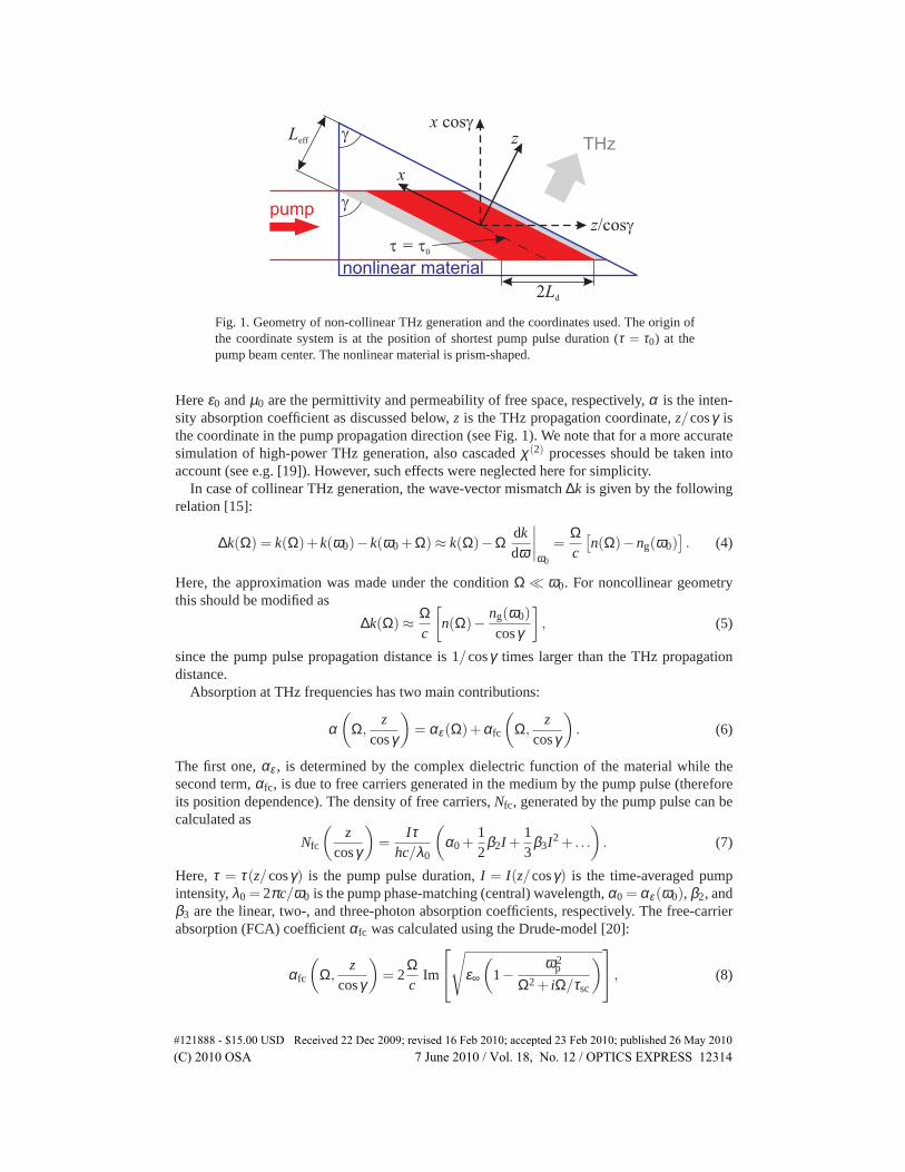
Fig. 1. Geometry of non-collinear THz generation and the coordinates used. The origin ofthe coordinate systemis at the position of shortest pump pulse duration (τ = τ0) at thepump beam center. The nonlinear material is prism-shaped.
Hereε0 andµ0 are the permittivity and permeability of free space, respectively,α is the inten-sity absorption coefficient as discussed below,z is the THz propagation coordinate,z/cosγ isthe coordinate in the pump propagation direction (see Fig. 1). We note that for a more accuratesimulation of high-power THz generation, also cascadedχ(2) processes should be taken intoaccount (see e.g. [19]). However, such effects were neglected here for simplicity.
In case of collinear THz generation, the wave-vector mismatch∆k is given by the followingrelation [15]:
∆k(Ω) = k(Ω)+k(ω0)−k(ω0 +Ω) ≈ k(Ω)−Ωdkdω
∣
∣
∣
∣
ω0
=Ωc
[
n(Ω)−ng(ω0)]
. (4)
Here, the approximation was made under the conditionΩ ≪ ω0. For noncollinear geometrythis should be modified as
∆k(Ω) ≈Ωc
[
n(Ω)−ng(ω0)
cosγ
]
, (5)
since the pump pulse propagation distance is 1/cosγ times larger than the THz propagationdistance.
Absorption at THz frequencies has two main contributions:
α(
Ω,z
cosγ
)
= αε(Ω)+αfc
(
Ω,z
cosγ
)
. (6)
The first one,αε , is determined by the complex dielectric function of the material while thesecond term,αfc, is due to free carriers generated in the medium by the pump pulse (thereforeits position dependence). The density of free carriers,Nfc, generated by the pump pulse can becalculated as
Nfc
(
zcosγ
)
=Iτ
hc/λ0
(
α0 +12
β2I +13
β3I2 + . . .
)
. (7)
Here,τ = τ(z/cosγ) is the pump pulse duration,I = I(z/cosγ) is the time-averaged pumpintensity,λ0 = 2πc/ω0 is the pump phase-matching (central) wavelength,α0 = αε(ω0), β2, andβ3 are the linear, two-, and three-photon absorption coefficients, respectively. The free-carrierabsorption (FCA) coefficientαfc was calculated using the Drude-model [20]:
αfc
(
Ω,z
cosγ
)
= 2Ωc
Im
√
ε∞
(
1−ω2
p
Ω2 + iΩ/τsc
)
, (8)
#121888 - $15.00 USD Received 22 Dec 2009; revised 16 Feb 2010; accepted 23 Feb 2010; published 26 May 2010(C) 2010 OSA 7 June 2010 / Vol. 18, No. 12 / OPTICS EXPRESS 12314
whereε∞ is the high-frequency dielectric constant,τsc is the electron scattering time,ωp =
eN1/2fc (ε0ε∞meff)
−1/2 is the plasma frequency,e andmeff are the electron charge and effectivemass, respectively. Note thatαfc depends on the pump propagation coordinatez/cosγ, sinceNfc depends on it. The material parameters used in the calculations are listed in Table 1.
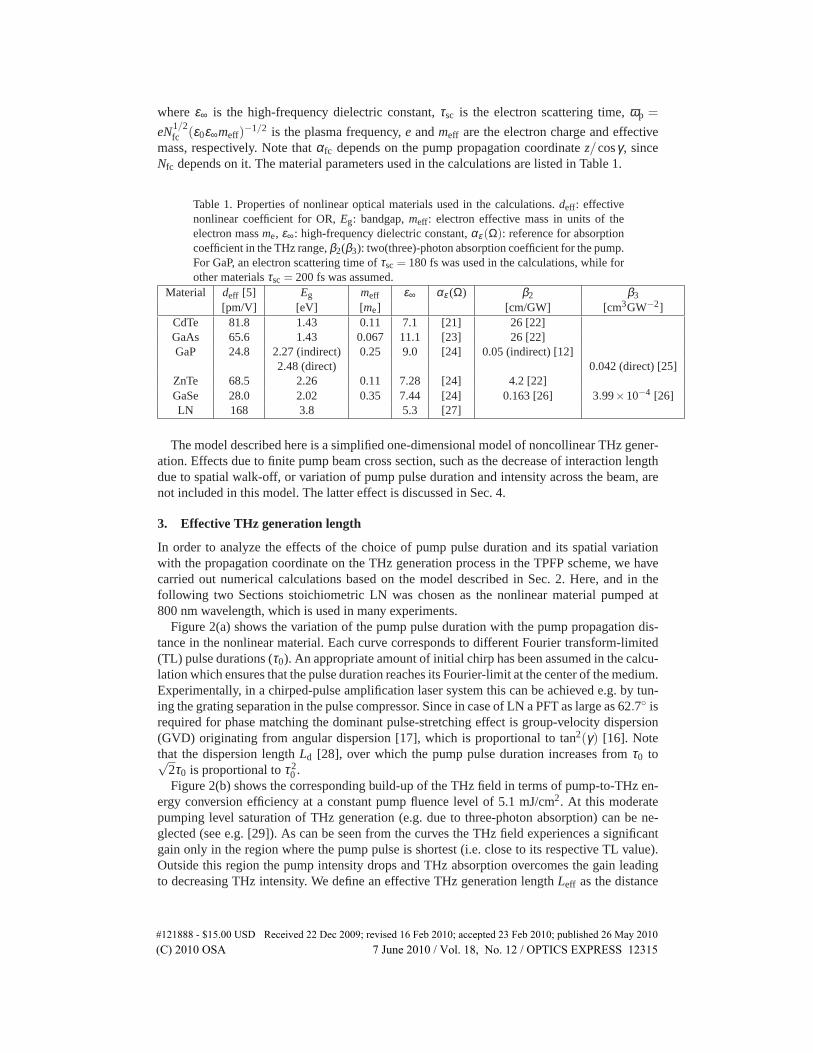
Table 1. Properties of nonlinear optical materials used in the calculations.deff: effectivenonlinear coefficient for OR,Eg: bandgap,meff: electron effective mass in units of theelectron massme, ε∞: high-frequency dielectric constant,αε (Ω): reference for absorptioncoefficient in the THz range,β2(β3): two(three)-photon absorption coefficient for the pump.For GaP, an electron scattering time ofτsc = 180 fs was used in the calculations, while forother materialsτsc = 200 fs was assumed.
Material deff [5] Eg meff ε∞ αε (Ω) β2 β3[pm/V] [eV] [me] [cm/GW] [cm3GW−2]
CdTe 81.8 1.43 0.11 7.1 [21] 26 [22]GaAs 65.6 1.43 0.067 11.1 [23] 26 [22]GaP 24.8 2.27 (indirect) 0.25 9.0 [24] 0.05 (indirect) [12]
2.48 (direct) 0.042 (direct) [25]ZnTe 68.5 2.26 0.11 7.28 [24] 4.2 [22]GaSe 28.0 2.02 0.35 7.44 [24] 0.163 [26] 3.99×10⁻⁴ [26]LN 168 3.8 5.3 [27]
The model described here is a simplified one-dimensional model of noncollinear THz gener-ation. Effectsdueto finite pump beam cross section, such as the decrease of interaction lengthdue to spatial walk-off, or variation of pump pulse duration and intensity across the beam, arenot included in this model. The latter effect is discussed in Sec. 4.
3. Effective THz generation length
In order to analyze the effects of the choice of pump pulse duration and its spatial variationwith the propagation coordinate on the THz generation process in the TPFP scheme, we havecarried out numerical calculations based on the model described in Sec. 2. Here, and in thefollowing two Sections stoichiometric LN was chosen as the nonlinear material pumped at800 nm wavelength, which is used in many experiments.
Figure 2(a) shows the variation of the pump pulse duration with the pump propagation dis-tance in the nonlinear material. Each curve corresponds to different Fourier transform-limited(TL) pulse durations (τ0). An appropriate amount of initial chirp has been assumed in the calcu-lation which ensures that the pulse duration reaches its Fourier-limit at the center of the medium.Experimentally, in a chirped-pulse amplification laser system this can be achieved e.g. by tun-ing the grating separation in the pulse compressor. Since in case of LN a PFT as large as 62.7 isrequired for phase matching the dominant pulse-stretching effect is group-velocity dispersion(GVD) originating from angular dispersion [17], which is proportional to tan2(γ) [16]. Notethat the dispersion lengthLd [28], over which the pump pulse duration increases fromτ0 to√
2τ0 is proportional toτ20 .
Figure 2(b) shows the corresponding build-up of the THz field in terms of pump-to-THz en-ergy conversion efficiency at a constant pump fluence level of 5.1 mJ/cm2. At this moderatepumping level saturation of THz generation (e.g. due to three-photon absorption) can be ne-glected (see e.g. [29]). As can be seen from the curves the THz field experiences a significantgain only in the region where the pump pulse is shortest (i.e. close to its respective TL value).Outside this region the pump intensity drops and THz absorption overcomes the gain leadingto decreasing THz intensity. We define an effective THz generation lengthLeff as the distance
#121888 - $15.00 USD Received 22 Dec 2009; revised 16 Feb 2010; accepted 23 Feb 2010; published 26 May 2010(C) 2010 OSA 7 June 2010 / Vol. 18, No. 12 / OPTICS EXPRESS 12315

-5 0 50
2
4
(b) Leff
THz propagation coordinate, z [mm]
THz
gene
ratio
n ef
ficie
ncy
[%
]
0
1
2
-20 -10 0 10 20
0 = 50 fs 0 = 100 fs 0 = 350 fs 0 = 600 fs
Pump propagation coordinate, z/cos [mm]Pu
mp
puls
e du
ratio
n,
[p
s]
2Ld
(a)
Fig. 2. Variation of pump pulse duration (a) and the corresponding THz generation effi-ciency (b)insidethe nonlinear material (LN) for various values of the TL pulse durationτ0.
#121888 - $15.00 USD Received 22 Dec 2009; revised 16 Feb 2010; accepted 23 Feb 2010; published 26 May 2010(C) 2010 OSA 7 June 2010 / Vol. 18, No. 12 / OPTICS EXPRESS 12316

0.0 0.1 0.2 0.3 0.4 0.5 0.60
1
2
3
4
5
0
2
4
6
8
10TH
z ge
nera
tion
effic
ienc
y [
%]
TL pump pulse duration, 0 [ps]
Effe
ctiv
e TH
z ge
nera
tion
leng
th, L
eff
[mm
]
Fig. 3. THz generation efficiency and effective THz generation lengthLeff in LN vs. TLpump pulse duration. The marked points correspond to the curves in Fig. 2.
measured in the THz propagation direction over which the THz intensity grows from 5% to itspeak value. For a particular pump pulse duration it is useful to choose the crystal dimensionsaccording to this effective length (see Fig. 1). The crystal should be positioned along the pumpbeam such that the maximum of the THz efficiency is reached at the crystal output surface.
For many experiments it is more important to reach the maximum THz field strength ratherthan the maximum conversion efficiency. An effective length can be defined for the THz peakelectric field strength in a similar manner. This length is usually shorter than that defined abovefor the efficiency since with increasing propagation length dispersion tends to broaden the THzpulse thereby decreasing its field strength.
Figure 3 shows the dependence of the maximal THz yield on the pump pulse duration at aconstant pump fluence level of 5.1 mJ/cm2 together with the effective THz generation lengthLeff. The useful crystal thickness in the THz propagation direction increases monotonically withthe pump pulse duration. In contrast to this, the corresponding THz generation efficiency has amaximum atτ0 = 350 fs, which indicates the optimal choice of pump pulse duration for high-energy THz pulse generation. For shorter TL pulse duration, theLeff effective length is small,which limits the THz yield. For longer TL pulse duration, the lower pump intensity results inlargerLeff, increased THz absorption, and reduced THz yield.
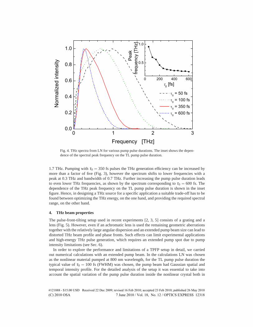
For many applications, such as THz time-domain spectroscopy, not only the THz pulse en-ergy is important but also its spectrum, i.e. bandwidth and position of spectral peak. Figure 4shows the normalized THz spectra for different pump pulse durations corresponding to the re-spective optimal crystal dimensions (see Fig. 3). In all cases phase matching was set for 1 THz.In case ofτ0 = 50 fs the spectral peak is located at 1.0 THz and the FWHM bandwidth is
#121888 - $15.00 USD Received 22 Dec 2009; revised 16 Feb 2010; accepted 23 Feb 2010; published 26 May 2010(C) 2010 OSA 7 June 2010 / Vol. 18, No. 12 / OPTICS EXPRESS 12317
0 1 2 30.0
0.2
0.4
0.6
0.8
1.0
0 200 400 600
0.5
1.0
Nor
mal
ized
inte
nsity
Frequency [THz]
0 = 50 fs 0 = 100 fs 0 = 350 fs 0 = 600 fs
frequ
ency
[TH
z]
0 [fs]
Peak
Fig. 4. THz spectra from LN for various pump pulse durations. The inset shows the depen-dence of thespectralpeak frequency on the TL pump pulse duration.
1.7 THz. Pumping withτ0 = 350 fs pulses the THz generation efficiency can be increased bymore than a factor of five (Fig. 3), however the spectrum shifts to lower frequencies with apeak at 0.3 THz and bandwidth of 0.7 THz. Further increasing the pump pulse duration leadsto even lower THz frequencies, as shown by the spectrum corresponding toτ0 = 600 fs. Thedependence of the THz peak frequency on the TL pump pulse duration is shown in the insetfigure. Hence, in designing a THz source for a specific application a suitable trade-off has to befound between optimizing the THz energy, on the one hand, and providing the required spectralrange, on the other hand.
4. THz beam properties
The pulse-front-tilting setup used in recent experiments [2, 3, 5] consists of a grating and alens (Fig. 5). However, even if an achromatic lens is used the remaining geometric aberrationstogether with the relatively large angular dispersion and an extended pump beam size can lead todistorted THz beam profile and phase fronts. Such effects can limit experimental applicationsand high-energy THz pulse generation, which requires an extended pump spot due to pumpintensity limitations (see Sec. 6).
In order to explore the performance and limitations of a TPFP setup in detail, we carriedout numerical calculations with an extended pump beam. In the calculations LN was chosenas the nonlinear material pumped at 800 nm wavelength, for the TL pump pulse duration thetypical value ofτ0 = 100 fs (FWHM) was chosen, the pump beam had Gaussian spatial andtemporal intensity profile. For the detailed analysis of the setup it was essential to take intoaccount the spatial variation of the pump pulse duration inside the nonlinear crystal both in
#121888 - $15.00 USD Received 22 Dec 2009; revised 16 Feb 2010; accepted 23 Feb 2010; published 26 May 2010(C) 2010 OSA 7 June 2010 / Vol. 18, No. 12 / OPTICS EXPRESS 12318
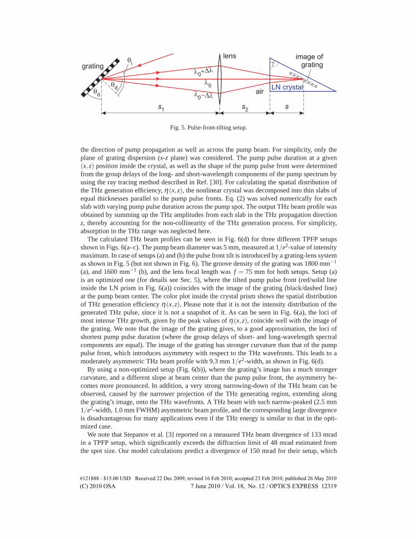
Fig. 5. Pulse-front-tilting setup.
the direction ofpumppropagation as well as across the pump beam. For simplicity, only theplane of grating dispersion (x-zplane) was considered. The pump pulse duration at a given(x,z) position inside the crystal, as well as the shape of the pump pulse front were determinedfrom the group delays of the long- and short-wavelength components of the pump spectrum byusing the ray tracing method described in Ref. [30]. For calculating the spatial distribution ofthe THz generation efficiency,η(x,z), the nonlinear crystal was decomposed into thin slabs ofequal thicknesses parallel to the pump pulse fronts. Eq. (2) was solved numerically for eachslab with varying pump pulse duration across the pump spot. The output THz beam profile wasobtained by summing up the THz amplitudes from each slab in the THz propagation directionz, thereby accounting for the non-collinearity of the THz generation process. For simplicity,absorption in the THz range was neglected here.
The calculated THz beam profiles can be seen in Fig. 6(d) for three different TPFP setupsshown in Figs. 6(a–c). The pump beam diameter was 5 mm, measured at 1/e2-value of intensitymaximum. In case of setups (a) and (b) the pulse front tilt is introduced by a grating-lens systemas shown in Fig. 5 (but not shown in Fig. 6). The groove density of the grating was 1800 mm−1
(a), and 1600 mm−1 (b), and the lens focal length wasf = 75 mm for both setups. Setup (a)is an optimized one (for details see Sec. 5), where the tilted pump pulse front (red/solid lineinside the LN prism in Fig. 6(a)) coincides with the image of the grating (black/dashed line)at the pump beam center. The color plot inside the crystal prism shows the spatial distributionof THz generation efficiencyη(x,z). Please note that it is not the intensity distribution of thegenerated THz pulse, since it is not a snapshot of it. As can be seen in Fig. 6(a), the loci ofmost intense THz growth, given by the peak values ofη(x,z), coincide well with the image ofthe grating. We note that the image of the grating gives, to a good approximation, the loci ofshortest pump pulse duration (where the group delays of short- and long-wavelength spectralcomponents are equal). The image of the grating has stronger curvature than that of the pumppulse front, which introduces asymmetry with respect to the THz wavefronts. This leads to amoderately asymmetric THz beam profile with 9.3 mm 1/e2-width, as shown in Fig. 6(d).
By using a non-optimized setup (Fig. 6(b)), where the grating’s image has a much strongercurvature, and a different slope at beam center than the pump pulse front, the asymmetry be-comes more pronounced. In addition, a very strong narrowing-down of the THz beam can beobserved, caused by the narrower projection of the THz generating region, extending alongthe grating’s image, onto the THz wavefronts. A THz beam with such narrow-peaked (2.5 mm1/e2-width, 1.0 mm FWHM) asymmetric beam profile, and the corresponding large divergenceis disadvantageous for many applications even if the THz energy is similar to that in the opti-mized case.
We note that Stepanov et al. [3] reported on a measured THz beam divergence of 133 mradin a TPFP setup, which significantly exceeds the diffraction limit of 48 mrad estimated fromthe spot size. Our model calculations predict a divergence of 150 mrad for their setup, which
#121888 - $15.00 USD Received 22 Dec 2009; revised 16 Feb 2010; accepted 23 Feb 2010; published 26 May 2010(C) 2010 OSA 7 June 2010 / Vol. 18, No. 12 / OPTICS EXPRESS 12319
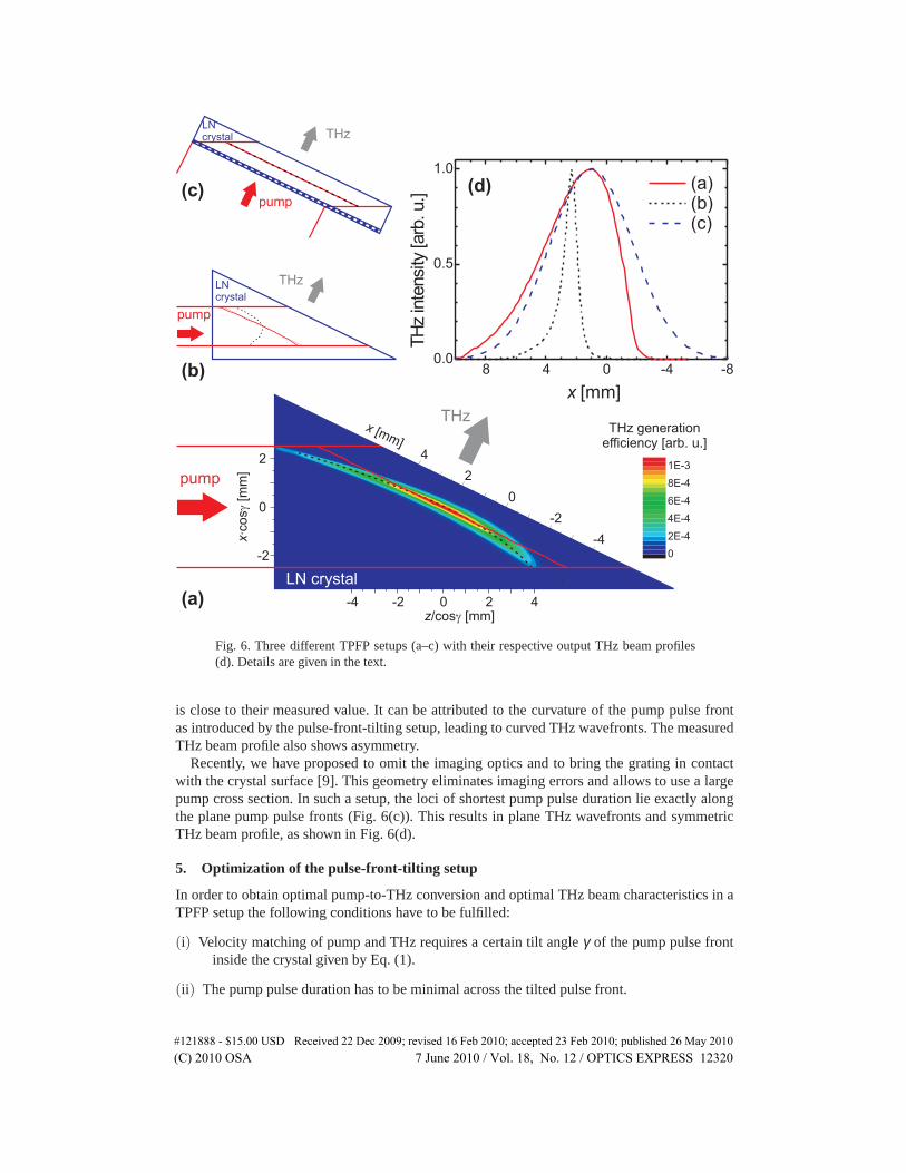
Fig. 6. Three different TPFP setups (a–c) with their respective output THz beam profiles(d). Details aregiven in the text.
is close to their measured value. It can be attributed to the curvature of the pump pulse frontas introduced by the pulse-front-tilting setup, leading to curved THz wavefronts. The measuredTHz beam profile also shows asymmetry.
Recently, we have proposed to omit the imaging optics and to bring the grating in contactwith the crystal surface [9]. This geometry eliminates imaging errors and allows to use a largepump cross section. In such a setup, the loci of shortest pump pulse duration lie exactly alongthe plane pump pulse fronts (Fig. 6(c)). This results in plane THz wavefronts and symmetricTHz beam profile, as shown in Fig. 6(d).
5. Optimization of the pulse-front-tilting setup
In order to obtain optimal pump-to-THz conversion and optimal THz beam characteristics in aTPFP setup the following conditions have to be fulfilled:
(i) Velocity matching of pump and THz requires a certain tilt angleγ of the pump pulse frontinside the crystal given by Eq. (1).
(ii) The pump pulse duration has to be minimal across the tilted pulse front.
#121888 - $15.00 USD Received 22 Dec 2009; revised 16 Feb 2010; accepted 23 Feb 2010; published 26 May 2010(C) 2010 OSA 7 June 2010 / Vol. 18, No. 12 / OPTICS EXPRESS 12320

(iii) The pump pulse front has to be plane in the crystal.
All conditionscan be fulfilled to very good accuracy in the contact-grating setup. In case ofsetups with imaging optics condition (ii) implies that the image of the grating should coincidewith the tilted pulse front over the whole pump beam cross section. Parameters of optimizedsetups satisfying conditions (i) and (approximately) (ii), such as in case of Fig. 6(a), can befound by simple analytical calculations based on paraxial ray optics, which will be outlinedbelow. Details of the calculations are given in the Appendix.
The pulse-front-tilting setup and its parameters are shown in Fig. 5. The incidence anddiffraction angles at the grating areθi andθd, respectively. Please note thatθd also gives the tiltangle of the grating (Fig. 5). Let us assume that the grating with a grating period length ofp andthe lens with a focal length off are given. Furthermore, we assume that the distancesbetweenthe image of the grating and the crystal input surface along the optical axis is also given.s isarbitrarily chosen such that the region of effective THz generation (gray-shaded area in Fig. 1)is not truncated. In case of givenp, f , ands parameters, and given nonlinear material, one canobtain (see Appendix) for the geometrical parameters of the setup (Fig. 5):
sinθd =λ0
n(λ0)ng(λ0)pa, (9)
sinθi = λ0/p−sinθd (grating equation), (10)
s1 = f(√
a+1)
, (11)
s2 =f s1
s1− f−
sn(λ0)
, (12)
wherea is given by:
a =n2(λ0)ng(λ0)p
2λ0
(√
λ 20
n2g(λ0)p2 tan4 γ
+4
n2(λ0)−
n2(λ0)
2tan2 γ
)
. (13)
Please note that for a given material and wavelengthθd depends on the grating period only.Therefore, according to Eq. (10), the angle of incidence,θi , also depends onp only.
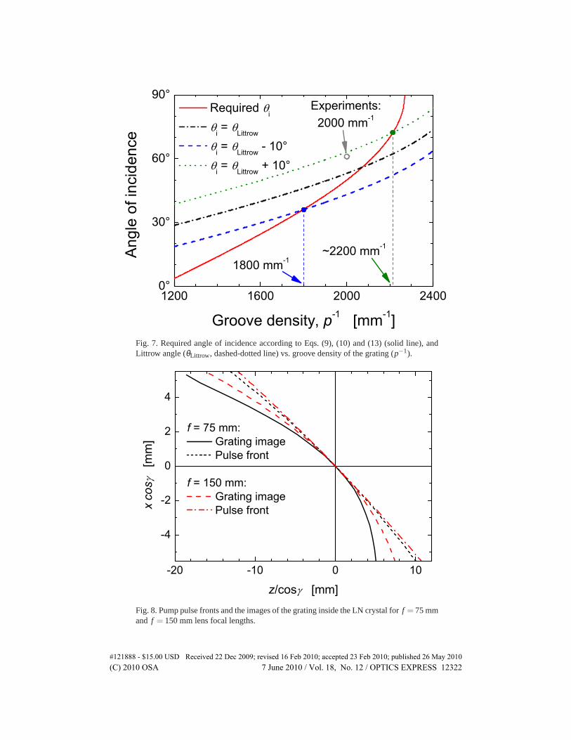
The solid line in Fig. 7 shows the required angle of incidence (θi) vs. the groove density of thegrating (p−1) calculated from Eqs. (9), (10), and (13) for LN,λ0 = 800 nm,Ω0/2π = 1 THz,and f = 75 mm. It is advantageous to use an incidence angle as close to the Littrow-angle,θLittrow = sin−1(λ0/2p), as practically possible, since the diffraction efficiency of a grating isusually maximal in Littrow-geometry (dashed-dotted line in Fig. 7). Hence, the grating periodp can be optimally chosen according toθi = θLittrow + ∆θ . Here,∆θ is a small (positive ornegative) deviation from the Littrow-angle necessary to separate the incident and the diffractedbeams (dashed and dotted lines in Fig. 7). The typical value of∆θ = −10 (+10) gives anoptimal groove density of 1800 mm−1 (2200 mm−1). In recent experiments 2000 mm−1 groovedensity andθi ≈ 60 were used [2, 5], which are not far from optimum (Fig. 7).
The effect of the lens focal lengthf was also investigated in case of the optimized setup, i.e.where the grating’s image coincides with the tilted pump pulse front at the beam center. Pumppulse fronts and images of the grating are compared in Fig. 8 forf = 75 mm, correspondingto the previous case in Fig. 6(a), andf = 150 mm when using the same grating and angle ofincidence. In case of the longer focal length the curvatures of both the pump pulse front andthe grating’s image are reduced. Thus, using longer focus is advantageous for reducing THzdivergence and THz beam asymmetry. We note that in order to further reduce the image-fieldcurvature a corrected flat-field lens can be used.
#121888 - $15.00 USD Received 22 Dec 2009; revised 16 Feb 2010; accepted 23 Feb 2010; published 26 May 2010(C) 2010 OSA 7 June 2010 / Vol. 18, No. 12 / OPTICS EXPRESS 12321
1200 1600 2000 24000°
30°
60°
90°
~2200 mm-1
Required i
i = Littrow
i = Littrow - 10° i = Littrow + 10°
Ang
le o
f inc
iden
ce
Groove density, p-1 [mm-1]
1800 mm-1
Experiments:2000 mm-1
Fig. 7. Required angle of incidence according to Eqs. (9), (10) and (13) (solid line), andLittrow angle(θLittrow , dashed-dotted line) vs. groove density of the grating (p−1).
-20 -10 0 10
-4
-2
0
2
4
f = 75 mm: Grating image Pulse front
f = 150 mm: Grating image Pulse frontx
cos
[m
m]
z/cos [mm]Fig. 8. Pump pulse fronts and the images of the grating inside the LN crystal forf = 75 mmand f = 150 mmlensfocal lengths.
#121888 - $15.00 USD Received 22 Dec 2009; revised 16 Feb 2010; accepted 23 Feb 2010; published 26 May 2010(C) 2010 OSA 7 June 2010 / Vol. 18, No. 12 / OPTICS EXPRESS 12322

6. Selection of the nonlinear material
In the designof a TPFP THz source the selection of the nonlinear material is a key step. Theeffective nonlinear coefficient, THz absorption, and phase matching between pump and THzfields are the most important issues to consider. The effective nonlinear coefficient of LN is oneof the highest among all materials suitable for OR. However, the large pulse front tilt requiredfor phase matching and the large absorption coefficient in the THz range can limit high-energyTHz pulse generation in LN. Therefore, it is of great practical importance to consider alternativematerials.
Some of the materials most suitable for OR are listed in Table 2. The PFT necessary forvelocity matching at 1 THz and the possible lowest order of linear or multiphoton pump ab-sorption are given for three practically important pump wavelengths (800 nm, 1064 nm and1560 nm). In all materials but LN a PFT ofγ ≈ 30 or smaller is sufficient for velocity match-ing, in contrast toγ ≈ 63 in LN. The much smaller angular dispersion, and hence, the reducedvariation of pump pulse duration can allow for longer effective THz generation lengths than inLN (GVD ∝ tan2(γ)). In some cases this can compensate for the smaller nonlinear coefficientof the semiconductor materials (see below). Please note that collinearly phase-matched THzgeneration is possible only in ZnTe near 800 nm pumping. Collinear pumping can eventuallybe used in cases where the PFT is smaller than about 10, such as GaP at∼ 1064 nm pumping[12]. However, for high-energy THz pulse generation with large pump beam diameters exactphase matching provided by TPFP is optimal. Table 2 also shows that in the considered ma-terials, only higher-order multiphoton absorption will be effective if longer pump wavelengthis used. This allows for higher pump intensities and more efficient THz generation, since freecarriers causing strong THz absorption will be generated by the pump only at higher intensities.
Table 2. The PFTγ necessary for velocity matching at 1 THz and the possible lowest orderof linear or multiphoton pump absorption for materials suitable for OR.λ0: pump wave-length; 1PA, 2PA, 3PA, etc.: linear, two-photon, three-photon, etc., absorption, respectively.
Material λ0 = 800 nm λ0 = 1064 nm λ0 = 1560 nmγ Pump absorption γ Pump absorption γ Pump absorption
CdTe – 1PA 9.6 2PA 28.6 2PAGaAs – 1PA – 2PA 6.2 2PAGaP – 2PA 9.3 indirect 2PA 20.0 indirect 3PAZnTe collinear 2PA 22.4 2PA 28.6 3PAGaSe 16.5 2PA 25.9 2PA 30.2 3PALN 62.7 3PA 63.4 4PA 63.8 5PA
In order to compare the performance of various materials, we carried out numerical calcula-tions based onthemodel described in Sec. 2. Figure 9 shows the maximal achievable pump-to-THz energy conversion efficiencies as a function of pump intensity (temporal average at beamcenter) for LN and some of the semiconductors. The TL pump pulse durationτ0 was chosensuch that the highest THz energy is obtained for a given pump fluence. The material lengthwas equal to the effective THz generation lengthLeff. In Fig. 9(a) phase matching was set for1 THz, while in Fig. 9(b) it was 3 THz and 5 THz. The saturation of THz generation appearsfor the semiconductor materials due to FCA caused by multiphoton absorption at the pumpwavelength. In lack of reliable data we have not included multiphoton absorption for LN in thecalculations. Experimentally, Hoffmann et al. [12] observed the saturation of THz generationabove 85 GW/cm2 pump intensity (shaded areas in Fig. 9), which can be attributed to FCA dueto four-photon absorption at 1064 nm pump wavelength. On the basis of this one can expectthat below this intensity level FCA has negligible influence on the THz yield and the numerical
#121888 - $15.00 USD Received 22 Dec 2009; revised 16 Feb 2010; accepted 23 Feb 2010; published 26 May 2010(C) 2010 OSA 7 June 2010 / Vol. 18, No. 12 / OPTICS EXPRESS 12323
0.1 1 10 100
10-4
10-3
10-2
10-1
100
101
3 = 4.2x10⁻² cm3 GW-2
Effi
cien
cy [%
]
Pump intensity [GW cm-2]
LN, 1064 nm GaP, 1064 nm
GaSe, 1064 nm GaSe, 1560 nm ZnTe, 1064 nm ZnTe, 1560 nm, 80 K ZnTe, 1560 nm, 80 K
(a) 0 = 1 THz 3 = 3.99x10⁻⁴ cm3 GW-2
0.0 0.5 1.0 1.5 2.00.0
0.5
1.0 (c) 0 = 1 THz
Nor
mal
ized
inte
nsity
Frequency [THz]
LN, 1064 nm GaP, 1064 nm GaSe, 1064 nm GaSe, 1560 nm ZnTe, 1560 nm,
80 K
3 = 3.99x10⁻⁴ cm3 GW-2
0.1 1 10 100
10-4
10-3
10-2
10-1
100
1010 = 5 THz
GaP, 1064 nm LN, 1064 nm
Effi
cien
cy [%
]
Pump intensity [GW cm-2]
0 = 3 THz GaP, 1064 nm GaAs, 1560 nm GaAs, 1800 nm LN, 1064 nm
(b)
0 1 2 3 4 5 60.0
0.5
1.0
0 = 5 THz LN, 1064 nm GaP, 1064 nm
Nor
mal
ized
inte
nsity
Frequency [THz]
0 = 3 THz LN, 1064 nm GaP, 1064 nm GaAs, 1800 nm
(d)
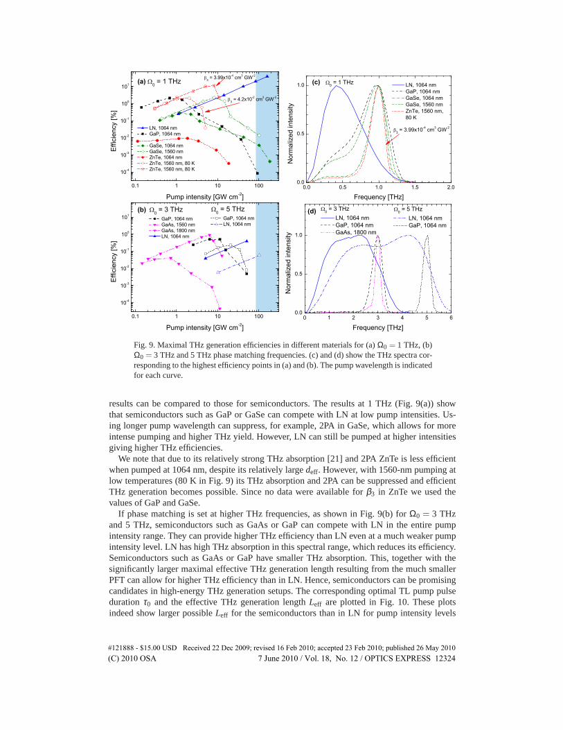
Fig. 9. Maximal THz generation efficiencies in different materials for (a)Ω0 = 1 THz, (b)Ω0 = 3 THz and 5 THz phase matching frequencies. (c) and (d) show the THz spectra cor-responding to the highest efficiency points in (a) and (b). The pump wavelength is indicatedfor each curve.
results can be compared to those for semiconductors. The results at 1 THz (Fig. 9(a)) showthat semiconductors such as GaP or GaSe can compete with LN at low pump intensities. Us-ing longer pump wavelength can suppress, for example, 2PA in GaSe, which allows for moreintense pumping and higher THz yield. However, LN can still be pumped at higher intensitiesgiving higher THz efficiencies.
We note that due to its relatively strong THz absorption [21] and 2PA ZnTe is less efficientwhen pumped at 1064 nm, despite its relatively largedeff. However, with 1560-nm pumping atlow temperatures (80 K in Fig. 9) its THz absorption and 2PA can be suppressed and efficientTHz generation becomes possible. Since no data were available forβ3 in ZnTe we used thevalues of GaP and GaSe.
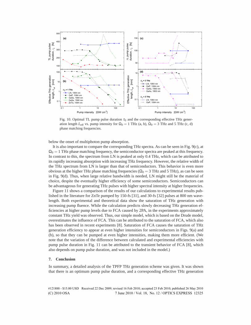
If phase matching is set at higher THz frequencies, as shown in Fig. 9(b) forΩ0 = 3 THzand 5 THz, semiconductors such as GaAs or GaP can compete with LN in the entire pumpintensity range. They can provide higher THz efficiency than LN even at a much weaker pumpintensity level. LN has high THz absorption in this spectral range, which reduces its efficiency.Semiconductors such as GaAs or GaP have smaller THz absorption. This, together with thesignificantly larger maximal effective THz generation length resulting from the much smallerPFT can allow for higher THz efficiency than in LN. Hence, semiconductors can be promisingcandidates in high-energy THz generation setups. The corresponding optimal TL pump pulsedurationτ0 and the effective THz generation lengthLeff are plotted in Fig. 10. These plotsindeed show larger possibleLeff for the semiconductors than in LN for pump intensity levels
#121888 - $15.00 USD Received 22 Dec 2009; revised 16 Feb 2010; accepted 23 Feb 2010; published 26 May 2010(C) 2010 OSA 7 June 2010 / Vol. 18, No. 12 / OPTICS EXPRESS 12324
100
200
300
400
500
TL p
ump
puls
e du
ratio
n,
0 [f
s]
(a)
0.1 1 10 100
0.1
1
10
100
(b)
Effe
ctiv
e TH
z ge
nera
tion
leng
th, L
eff
[mm
]
Pump intensity [GW cm-2]
0 = 1 THz LN, 1064 nm GaP, 1064 nm GaSe, 1064 nm GaSe, 1560 nm ZnTe, 1064 nm
50
100
150
TL p
ump
puls
e du
ratio
n,
0 [f
s]
(c)
0.1 1 10 100
0.1
1
10
0 = 5 THz LN, 1064 nm GaP, 1064 nm
(d)
Effe
ctiv
e TH
z ge
nera
tion
leng
th, L
eff
[mm
]
Pump intensity [GW cm-2]
0 = 3 THz LN, 1064 nm GaP, 1064 nm GaAs, 1560 nm GaAs, 1800 nm
Fig. 10. Optimal TL pump pulse durationτ0 and the corresponding effective THz gener-ation lengthLeff vs. pump intensity forΩ0 = 1 THz (a, b),Ω0 = 3 THz and 5 THz (c, d)phase matching frequencies.
below the onset of multiphoton pump absorption.It is also important to compare the corresponding THz spectra. As can be seen in Fig. 9(c), at
Ω0 = 1 THz phase matching frequency, the semiconductor spectra are peaked at this frequency.In contrast to this, the spectrum from LN is peaked at only 0.4 THz, which can be attributed toits rapidly increasing absorption with increasing THz frequency. However, the relative width ofthe THz spectrum from LN is larger than that of semiconductors. This behavior is even moreobvious at the higher THz phase matching frequencies (Ω0 = 3 THz and 5 THz), as can be seenin Fig. 9(d). Thus, when large relative bandwidth is needed, LN might still be the material ofchoice, despite the eventually higher efficiency of some semiconductors. Semiconductors canbe advantageous for generating THz pulses with higher spectral intensity at higher frequencies.
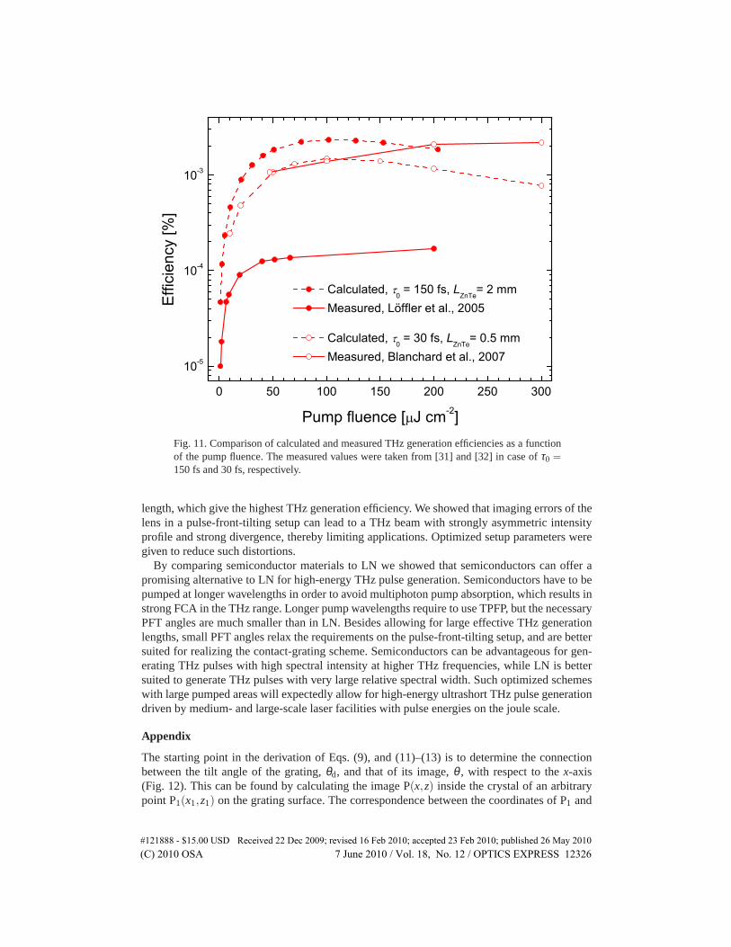
Figure 11 shows a comparison of the results of our calculations to experimental results pub-lished in the literature for ZnTe pumped by 150-fs [31], and 30-fs [32] pulses at 800 nm wave-length. Both experimental and theoretical data show the saturation of THz generation withincreasing pump fluence. While the calculation predicts slowly decreasing THz generation ef-ficiencies at higher pump levels due to FCA caused by 2PA, in the experiments approximatelyconstant THz yield was observed. Thus, our simple model, which is based on the Drude model,overestimates the influence of FCA. This can be attributed to the saturation of FCA, which alsohas been observed in recent experiments [8]. Saturation of FCA causes the saturation of THzgeneration efficiency to appear at even higher intensities for semiconductors in Figs. 9(a) and(b), so that they can be pumped at even higher intensities, making them more efficient. (Wenote that the variation of the difference between calculated and experimental efficiencies withpump pulse duration in Fig. 11 can be attributed to the transient behavior of FCA [8], whichalso depends on pump pulse duration, and was not included in the model.)
7. Conclusion
In summary, a detailed analysis of the TPFP THz generation scheme was given. It was shownthat there is an optimum pump pulse duration, and a corresponding effective THz generation
#121888 - $15.00 USD Received 22 Dec 2009; revised 16 Feb 2010; accepted 23 Feb 2010; published 26 May 2010(C) 2010 OSA 7 June 2010 / Vol. 18, No. 12 / OPTICS EXPRESS 12325
0 50 100 150 200 250 300
10-5
10-4
10-3
Effi
cien
cy [%
]
Pump fluence [ J cm-2]
Calculated, 0 = 150 fs, L
ZnTe= 2 mm
Measured, Löffler et al., 2005
Calculated, 0 = 30 fs, L
ZnTe= 0.5 mm
Measured, Blanchard et al., 2007
Fig. 11. Comparison of calculated and measured THz generation efficiencies as a functionof the pumpfluence.The measured values were taken from [31] and [32] in case ofτ0 =150 fs and 30 fs, respectively.
length, which give the highest THz generation efficiency. We showed that imaging errors of thelens in a pulse-front-tilting setup can lead to a THz beam with strongly asymmetric intensityprofile and strong divergence, thereby limiting applications. Optimized setup parameters weregiven to reduce such distortions.
By comparing semiconductor materials to LN we showed that semiconductors can offer apromising alternative to LN for high-energy THz pulse generation. Semiconductors have to bepumped at longer wavelengths in order to avoid multiphoton pump absorption, which results instrong FCA in the THz range. Longer pump wavelengths require to use TPFP, but the necessaryPFT angles are much smaller than in LN. Besides allowing for large effective THz generationlengths, small PFT angles relax the requirements on the pulse-front-tilting setup, and are bettersuited for realizing the contact-grating scheme. Semiconductors can be advantageous for gen-erating THz pulses with high spectral intensity at higher THz frequencies, while LN is bettersuited to generate THz pulses with very large relative spectral width. Such optimized schemeswith large pumped areas will expectedly allow for high-energy ultrashort THz pulse generationdriven by medium- and large-scale laser facilities with pulse energies on the joule scale.
Appendix
The starting point in the derivation of Eqs. (9), and (11)–(13) is to determine the connectionbetween the tilt angle of the grating,θd, and that of its image,θ , with respect to thex-axis(Fig. 12). This can be found by calculating the image P(x,z) inside the crystal of an arbitrarypoint P1(x1,z1) on the grating surface. The correspondence between the coordinates of P1 and
#121888 - $15.00 USD Received 22 Dec 2009; revised 16 Feb 2010; accepted 23 Feb 2010; published 26 May 2010(C) 2010 OSA 7 June 2010 / Vol. 18, No. 12 / OPTICS EXPRESS 12326
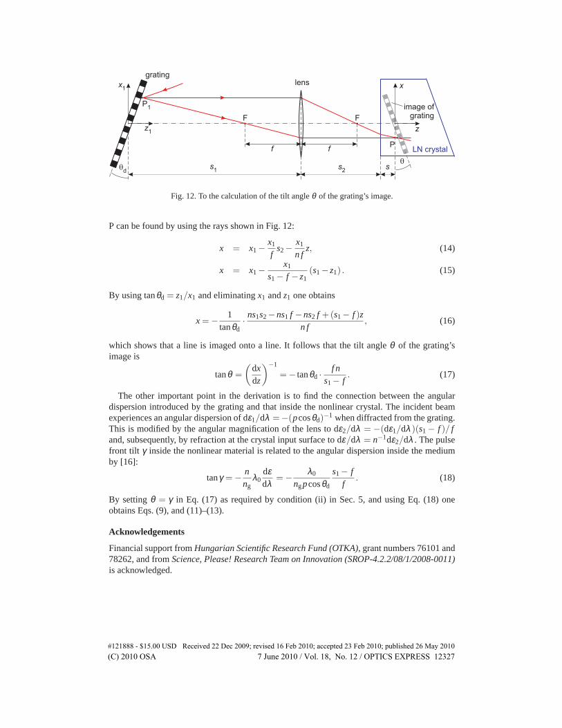
Fig. 12. To the calculation of the tilt angleθ of the grating’s image.
P can be found by using the rays shown in Fig. 12:
x = x1−x1
fs2−
x1
n fz, (14)
x = x1−x1
s1− f −z1(s1−z1) . (15)
By using tanθd = z1/x1 and eliminatingx1 andz1 one obtains
x = −1
tanθd·ns1s2−ns1 f −ns2 f +(s1− f )z
n f, (16)
which showsthat a line is imaged onto a line. It follows that the tilt angleθ of the grating’simage is
tanθ =
(
dxdz
)−1
= − tanθd ·f n
s1− f. (17)
The other importantpoint in the derivation is to find the connection between the angulardispersion introduced by the grating and that inside the nonlinear crystal. The incident beamexperiences an angular dispersion of dε1/dλ =−(pcosθd)
−1 when diffracted from the grating.This is modified by the angular magnification of the lens to dε2/dλ = −(dε1/dλ )(s1− f )/ fand, subsequently, by refraction at the crystal input surface to dε/dλ = n−1dε2/dλ . The pulsefront tilt γ inside the nonlinear material is related to the angular dispersion inside the mediumby [16]:
tanγ = −nng
λ0dεdλ
= −λ0
ngpcosθd
s1− ff
. (18)
By settingθ = γ in Eq. (17) as required by condition (ii) in Sec. 5, and using Eq. (18) oneobtains Eqs. (9), and (11)–(13).
Acknowledgements
Financial support fromHungarian Scientific Research Fund (OTKA), grant numbers 76101 and78262, and fromScience, Please! Research Team on Innovation (SROP-4.2.2/08/1/2008-0011)is acknowledged.
#121888 - $15.00 USD Received 22 Dec 2009; revised 16 Feb 2010; accepted 23 Feb 2010; published 26 May 2010(C) 2010 OSA 7 June 2010 / Vol. 18, No. 12 / OPTICS EXPRESS 12327