design of thermally induced seizure in journal bearings ... · hari shankar vanka assistant...
TRANSCRIPT

Page 1055
Design of Thermally Induced Seizure in Journal Bearings During
Start Up Using Ansys
I.Suresh
M.Tech Student,
Department of Mechanical Engineering,
Visakha Technical Camps.
Hari Shankar Vanka
Assistant Professor,
Department of Mechanical Engineering,
Visakha Technical Campus.
Abstract: Transient thermo-elastic behavior of journal bearing
during seizure is very complex and requires careful
modeling of the interaction of the surface. In this
project work a finite element model is used to describe
the thermo-mechanical interactions of journal bearing
undergoing Thermally Induced Seizure (TIS), two
categories of TIS are studied. The first part deals with
occurrence of seizure during start up period followed
by an investigation of TIS due to the transient flow
disturbance. An extensive set of parametric
simulations are performed to study the effect of
different parameters on TIS such as load, speed, shaft
radius, operating clearance, bearing length, friction
coefficient and thermal expansion coefficient. Good
agreement between empirical results and the results
obtained from this model attests the capability of the
model and its potential for predicting thermally
induced seizure phenomenon.
Introduction:
Thermally Induced Seizure in the journal bearing is a
mode of failure that occurs quite suddenly and end up
causing the catastrophic damage to the system.
Eventhough hydrodynamic bearings are applied in
practical applications over a wide range of speeds,
loads etc. extensive research efforts are still going on
to have better understanding of their behavior. The
relative sliding motion between the two contacting
solids generally results in loss of mechanical energy
due to friction. The power dissipation associated with
friction is manifested in the form of heat generation at
the contacting surfaces and results in an increase in
temperature of sliding bodies. Many widely used
mechanical components, such as bearings, seals,
brakes and clutches are susceptible to frictional
heating. This report investigates the effect of frictional
heating on the operating clearance in a journal
bearing.Operating clearance is one of the important
variables in the performance of journal bearing. The
variation of clearance with time is of significant
practical interest particularly for situations where large
frictional heat is produced as a result of dry contact.
The deformation associated with expansion of the
rotating shaft relative to that of the stationary bearing
may be quite large, to the extent that a complete loss of
clearance may take place with a catastrophic seizure.
This seizure phenomenon commonly occurs during the
startup process when shaft is in direct contact with
bush. Particularly susceptible to seizure are bearings
that have not been used for a relatively long period of
time or when the lubricant supply to the bearing is
blocked thus during the startup process the shaft and
the bush are in direct contact with an associated high
friction coefficient. Under these circumstances one
would like to be able to predict how long it takes
before the seizure may set in. The objective of this
work is to perform a comprehensive study of seizure in
bearings during start up and when a transient flow

Page 1056
disturbance is occurred and alive at seizure time which
is a function of various parameters. The finite element
modeling is done using ANSYS .
A simplified two-dimensional analysis is performed,
the analysis assumes that the contact pressure is
uniform in axial direction and that no crowning or
misalignment is present in the system.
The analysis of a bearing undergoing TIS during
start up consist of the following steps:
1. A 2-D static contact analysis is to be performed to
determine the contact forces and the contact angle.
2. A transient heat transfer analysis is to be performed
to model thermal effects of dry frictional heating on
the journal and the bearing.
3. A transient thermo-elastic analysis is to be
performed to study the interactions of the journal-
bearing pair during bearing start-up. The variation of
radial clearance, contact forces and ovalization of the
bearing are to be studied in this analysis.
Description of problem:
The model consists of a shaft rubbing on the inner
surface of the bushing as shown in Figure 4.1. Under
load frictional heat is generated at the contact between
the rotating shaft and the stationary bearing. A loss of
clearance occurs due to relative thermal expansion, as
can be seen in the Fig.4.1 the initial cold clearance
varies from zero to a maximum. During the thermal
transient, the encroachment is a complex function of
the various parameters, material properties and
boundary conditions.
Figure 4.1 – Schematic of a journal supported on a
pillow block
The total heat generated in the contact region is
partitioned between the journal and bushing. When the
shaft expands relative to the bushing, the increase in
the frictional torque leads to an increase in the
frictional heat generated at the contact. As the
clearance loss progresses, a larger percentage of the
total frictional heat enters the bushing due to increased
area of contact and the contact conductance with the
shaft.
4.1.2 Analysis Model:
The model consists of a shaft rubbing on the inner
surface of the bushing as shown in Figure 4.1. The
contact forces results in the generation of frictional
heat on the entire surface of the shaft and in the area
where it contacts the bushing inner radius. Due to the
rise in temperature, the shaft expands and its
encroachment to the bushing leads to a loss of
clearance. At some point in time, the bearing clearance
reduces to a minimum and shaft starts to encroach the
bearing. Analysis show that typically during TIS, the
following three phenomena occur:

Page 1057
(i) The contact forces increase, increasing the
heat generated.
(ii) The contact angle increases causing a
higher percentage of heat entering
the bush.
(iii) New areas of contacts are established
resulting in a chain reaction of events
leading to a rapid loss in the operating
clearance.
The simulations presented in this work, are
implemented by performing a thermal analysis and a
thermo-elastic analysis in a stepwise linear fashion.
The model utilized for analysis is one-half symmetry
and the heat conduction in the axial direction
neglected. The operating parameters used for this
model are listed below:
Loading:
The loading for the static contact analysis
is applied to act in the negative Y-direction on the
shaft. As the model utilizes the half symmetry, a load
of W/2 is applied.
Figure4.2 Meshing of the shaft
Figure4.3Displacement is constrained in
X- an direction for all starting nodes & in
Y- direction for bottom and top most nodes
Boundary Conditions:
Symmetry boundary conditions in the X direction are
used to model one-half symmetry and to avoid the
rigid body motion in Y direction, we are constraining
two nodes on bushing in X and Y directions so that the
body will not move freely in the space under the
applied loads. The loading and boundary conditions
are shown in Fig.4.3. The contact angle and the contact
forces will be obtained from structural contact
analysis. According to this model, it is calculated that
the contact angle is approximately 17 for one-half
symmetry. The analysis shows that for this contact
angle the contact forces act only at four nodes as
shown in the Figure 4.4.
Load

Page 1058
Fig.4.4 Contact force reactions due to initial static
Step-2: Transient Thermal Finite Element Analysis
Thermal Element:
The thermal analysis is done to determine the
temperature distribution in the journal-bushing pair.
The journal and bushing are modeled as 4-noded solid
thermal elements viz. PLANE55. The PLANE55
element has a single degree of freedom, namely
temperature at each node. It is noted that the elements
at the center of the shaft degenerates to triangles. This
element is compatible with the 4-noded structural solid
element used in the thermo-mechanical analysis. The
results of the thermal analysis can be successfully
exported to perform the thermo-elastic analysis.Two-
node convection link element, designated as LINK34
in ANSYS used to represent the thermal contact
resistance in the annular clearance. The convection
link, shown in Figure 4.5, is a uniaxial element with
the ability to convect heat between at its nodal points.
The element has single degree of freedom,
temperature, at each node point.
Figure 4.5. Convection link between shaft and
bushing.
Material properties and loading:
The material properties required for the thermal solid
elements are Thermal conductivity, k, Density, and
specific heat Cp. Thermal convection LINK element
requires effective heat transfer coefficient (he) as input
at the interface between the shaft and bushing. It
should be noted that in the absence of contact, he is
assumed to be equal to zero, that is no heat flow is
assumed across the clearance. The area of contact is
required for the convection link to calculate heat
entering the bush per unit area. Since link is a line
element, the method used to compute the areas can be
seen in to Fig.4.5. For convection link 1, on the
symmetry plane, if node i1 on the shaft is in contact
with node j1 on the bushing the area of contact is
computed based on one-half the distance to convection
link 2. Likewise, for convection link 2, if node i2 is in
contact with node j2 the area of contact is equal to one-
half the distance to link 1 plus one-half the distance to
convection link 3.
Page 1059
The loading applied to the model consists of the heat
generated due to the frictional contact. The total
frictional heat generated in the contact zone is:
Q=fu∑P--------------------(1)
Where f is the friction coefficient of the rubbing
surfaces,
P is the contact forces and
u is the velocity of rotation.
The heat generated at the interface is conducted both
through the shaft and the bushing. It can be assumed
that the partition of heat between the bodies is
proportional to the contact area and the heat capacities
of the surfaces. Therefore, the heat transferred through
the shaft and bushing is:
Qs=QAs/(As+Ab) --------------------(2)
And
Qb=QAb/(As+Ab)----------------(3)
The heat transferred to the stationary bush occurs over
the contact arc,
Ab=RboL---------------- (4)
While the entire surface of the rotating shaft comes
into contact with the bush,
As=2RsL-----------------(5)
Where
L is the length of the bushing in the axial direction.
Since Rs=Rb it can be seen from Eqs(2)-(5) that
Qb<=Qs. it is only when the bearing and shaft are in
full contact, ie when o=2, that Qb=Qs.
According to M.M. Khonsari and H.J.Kim it is
reasonable to assume that the heat entering the shaft
can be averaged over the entire circumference,
therefore, the heat flux applied to the surface of the
shaft is:
qs=Q/(As+Ab) -----------------(6)
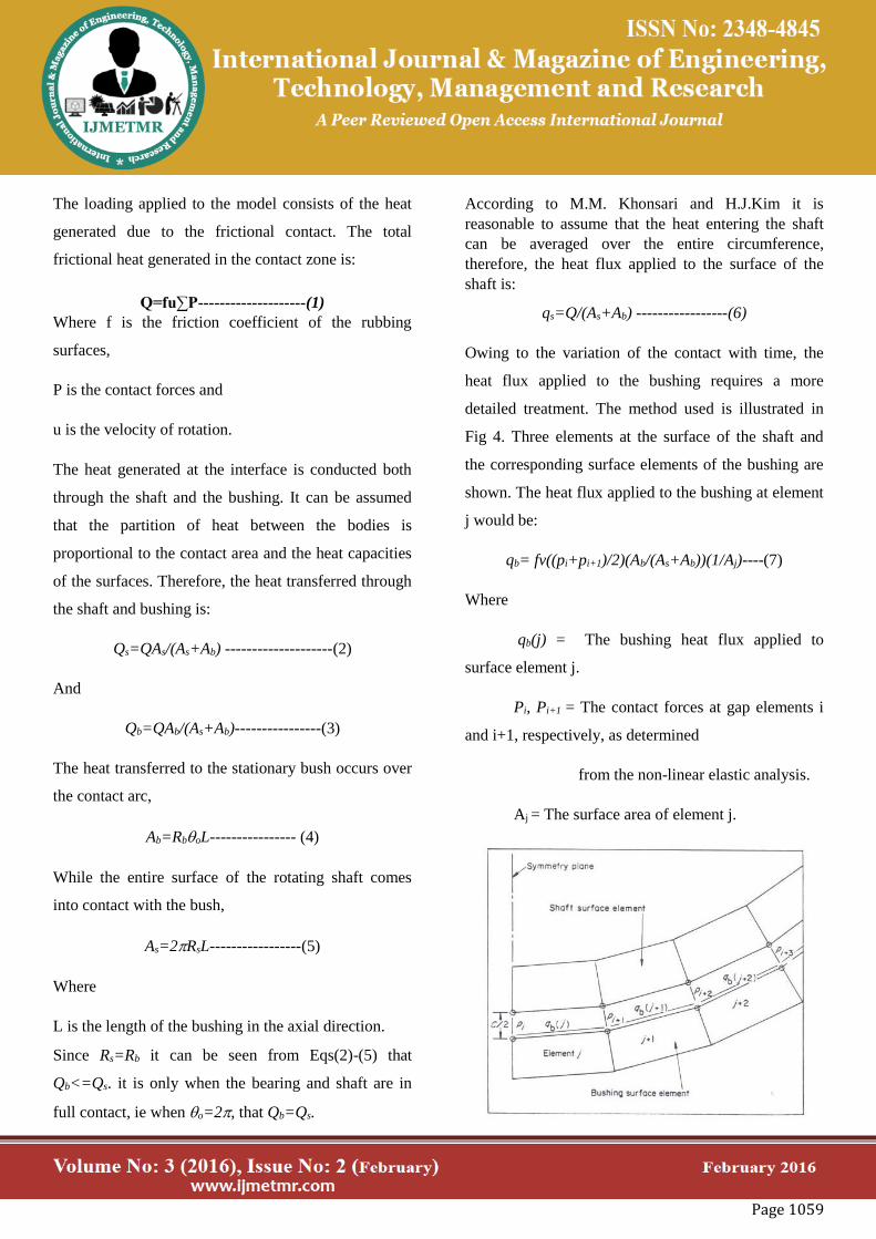
Owing to the variation of the contact with time, the
heat flux applied to the bushing requires a more
detailed treatment. The method used is illustrated in
Fig 4. Three elements at the surface of the shaft and
the corresponding surface elements of the bushing are
shown. The heat flux applied to the bushing at element
j would be:
qb= fv((pi+pi+1)/2)(Ab/(As+Ab))(1/Aj)----(7)
Where
qb(j) = The bushing heat flux applied to
surface element j.
Pi, Pi+1 = The contact forces at gap elements i
and i+1, respectively, as determined
from the non-linear elastic analysis.
Aj = The surface area of element j.

Page 1060
Figure 4.6 Method of applying heat flux to the
bushing
Boundary conditions:
The boundary conditions used in the transient heat
conduction analysis consist of the convective heat
transfer coefficient at the external surfaces. The
rotating shaft is heated periodically as it makes contact
with the bushing. It was shown by Hazlet, that the on-
off frictional heating could be applied as an average
heat flux over the entire shaft surface.
Also, there is dissipation of heat by convective cooling
by the air within the clearance of the journal and the
bushing. In addition to the periodic heating, the shaft
periodically dissipates heat as it comes into contact
with the bushing. To represent the periodic heat
dissipation in the finite element model, the nodes on
the surface of the shaft are coupled. The temperature
on the surface of the journal and the bushing at the
interface is constant and is modeled by coupling the
temperatures at the nodes on the interface. The outer
surface of the bushing is subject to natural convection.
Thermal boundary conditions and thermal loads are
schematically represented in Figure 4.7.
(a) Applying heat flux
(b) Applying convection
(c) Applying bulk temperature
(d) Coupling the temperatures at the nodes on the
interface
Figure 4.7 Boundary conditions and Thermal loads
for transient thermal analysis

Page 1061
Step3: Non-linear Transient Elastic Finite Element
Analysis:
Element type:
Two types of elements are used in the non-linear
elastic model. The shaft and bush utilizes two
dimensional isoperimetric plane stress solid element
designated by PLANE42. The element is defined by
four nodal points having two degrees of freedom at
each node, translation in the nodal X and Y directions.
The theory for the element is based on the formulation,
which includes modified extra displacement shapes.
The radial clearance between the journal and the bush
is modeled using two-noded contact elements, namely
CONTAC12. Contact elements are used to model gap
and they come into effect only when the two nodes
that make the element come into contact.
Material properties and loading:
The material properties required for the solid elements
are Elastic modulus, E, Poisson’s ratio, v, and
Coefficient of thermal expansion, . No material
properties are required for contact elements.
The loading for the non-linear thermo-elastic analysis
consists of the thermal loads applied as nodal
temperatures and the radial force acting on the journal.
The time dependent thermal load is obtained from the
results of the transient thermal analysis. The static
load, W is applied to act in the negative y-direction on
the shaft. As the model utilizes half-symmetry, a load
of W/2 is applied.
Boundary Conditions:
Symmetry boundary conditions are used to model the
one-half symmetry as shown in Fig.4.3 The constraint
of the bearing on its outer surface is modeled by fixing
the bearing at the node under the shaft on the outer
edge of the bearing on the symmetry plane. This
constraint approximates the boundary conditions of the
bottom surface of the bearing support structure as
shown in Figs.4.1 and 4.3.
4.1.3 Seizure Criterion:
Frictional torque is the torque resisting the driving
torque exerted by the motor. When the frictional
torque increases beyond the extent of the driving
torque capability, it can be concluded that the journal
has seized in the bearing. The present model assumes
that TIS is complete when the frictional torque reaches
at least 50 times the driving torque. The contact forces’
acting on the gap elements at any instant of time
determines the frictional torque at any time and is
computed using the following equation
1
2m
s i
i
t f R P t
Where
(t) is the frictional torque,
f is the coefficient of friction,
Rs is the radius of the shaft,
Pi is the contact force at the ith gap element,
and

Page 1062
m is the number of elements in contact.
4.2 Results and Discussion:
The encroachment of the shaft on to the bushing with
concomitant reduction in the clearance continues until
the seizure is complete. The process is a complex,
nonlinear phenomenon. Analysis shows that TIS is
initiated by the ovalization of the bearing combined
with the uniform outward expansion of the shaft
yielding contact between the top of the shaft and the
inner bushing surface. This leads to an increase in the
contact forces and the formation of an extra contact
area. Increase of contact forces raises the frictional
heat flux and sets up a positive feedback that
accelerates the loss of clearance. The increase in the
frictional torque is abrupt once the ovalization of the
bearing causes the shaft to encroach the bushing, as
there is further loss in the operating clearance. The
frictional torque increased to exceedingly large values
within few seconds after the first instance of
establishment of new areas of contact. The reasons for
such an abrupt increase in frictional torque are:
(i) As explained previously, the increase in contact
forces increases the frictional heat generated and the
increase in frictional heat means that the shaft would
expand more increasing the contact forces and
establishing more area of contact. This process leads to
a positive feedback loop and a chain reaction leading
to a rapid failure due to TIS.
(ii) The operating clearance of the bearing just before
seizure is reduced to a significantly
lower value compared to the steady-state operating
clearance. This is due to the thermal expansion of the
journal and the bearing into the operating clearance
area. The available clearance just before the extra
contact occurs has already reduced to an exceedingly
smallvalue.
Seizure time:
When the frictional torque increases beyond the extent
of the driving torque capability, it can be concluded
that the journal has seized in the bearing. The present
model assumes that TIS is complete when the
frictional torque reaches at least 50 times the driving
torque. For the following operating parameters the
frictional and driving torque values for the first 30
seconds are shown in the Table 4.1.
Operating parameters:
W = 4400 N N = 250 rpm
Rs = 25.5 x 10⁻³ m Rb = 51.0 x 10⁻³ m
C = 0.0125 x 10⁻³ m L = 51.0 x 10⁻³ m
Table 4.1
Time Frictional Torque Driving Torque
1 17.011 112.2
2 17.013 112.2
3 17.017 112.2
4 17.02 112.2
5 17.04 112.2
6 17.05 112.2
7 17.08 112.2
8 17.237 112.2
9 17.287 112.2
10 17.917 112.2
11 17.514 112.2
12 18.924 112.2
13 22.479 112.2
14 220.397 112.2

Page 1063
15 613.38 112.2
16 1030.36 112.2
17 1471.072 112.2
18 1935.252 112.2
19 2422.641 112.2
20 2932.984 112.2
21 3466.028 112.2
22 4021.525 112.2
23 4599.231 112.2
24 5198.904 112.2
25 5820.309 112.2
26 6463.213 112.2
27 7127.38 112.2
28 7812.608 112.2
29 8518.654 112.2
30 9245.311 112.2
From the above table at 25 seconds of time the
frictional torque reached 50 times more than the
driving torque. Therefore seizure time for the above
given parameters is 25 seconds.
Temperature distribution, Contact force reactions and
Deformation of shaft at 12 & 25 seconds during the
analysis are shown below in the Figures 4.8 & 4.9.
Contact forces list at 12 & 25 seconds are shown in the
Tables 4.2 & 4.3.
During this, it is observed that temperature rise is the
function of time and those plots illustrate the onset and
completion of seizure for a journal bearing during
start-up.
Table (4.2) Contact forces list at 12 seconds
Table (4.2) Contact forces list at 25 seconds
Node
numbe
r
Contac
t force
Node
numbe
r
Contac
t force
Node
numbe
r
Contac
t force
641 22734 652 23641 663 22528
642 23064 653 23112 664 23138
643 23524 654 22669 665 22990
644 23185 655 23968 666 22474
645 23541 656 23631 667 22447
646 23205 657 23544 668 22851
647 23497 658 22832 669 22448
648 23265 659 22710 670 22725
649 23391 660 23425 671 22478
650 23502 661 22608 672 22619
651 23257 662 23285 673 22537
Node
number
Contact force
641 356.15
644 351.18
646 318.29
648 297.18
650 337.58
652 333.19
654 274.75
656 173.51
657 31.923

Page 1064
4.8 (a) Temperature distribution
4.8 (b) Contact forces reactions
4.8 (c) Deformation of shaft
4.9 (a) Temperature distribution
4.9.(b)Contact forces reactions
4.9 (c) Deformation of shafts
Figures 4.8 & 4.9.Simulated results after 12 & 25
seconds

Page 1065
4.3 Verification and Analysis:
The simulated results are verified for its validity using
some of the results published by Hazlett and Khonsari
[8,9], Wang, Conry and Cusano [10] and Bishop and
Ettles [5]. The comparisons between simulated results
and some of the published results are shown in Table 4
Table (4.4) comparison of results
To gain further insight into the TIS behavior, we plot
the change in the operating clearance as a function of
time based in Dufrane and Kannel's equation (4.1) and
the simulated results in the present study are shown in
Figure 4.10 for two heat partitioning factors (n = 0.5
and 1).ANSYS 7.1 calculates the heat-partitioning
factor based on the thermal mass andmaterial
properties at the contact area such that there is
continuity of temperature and fluxat the contact
interface.
A heat partitioning of 1 is not reasonable as it means
that all the frictional heat generated would be
transmitted into the shaft. The analysis done by
Dufrane and Kannel [6] did not consider the expansion
of the bushing, the thermal expansion of the shaft was
only considered. Also, the bushing was rigidly
constrained. As
the present study has considered the bushing constraint
the outward expansion of the bushing, the seizure
times were larger than the values obtained using
Equation (4.1) used by Dufrane and Kannel. From
Figure 4.10, it can be seen that the present model
compares close to Dufrane and Kannel's model when a
heat-partitioning factor of 0.5 is used in Equation (1).
The seizure time formula developed in this study
predicts the loss of clearance with time is not a linear
process. Whereas Equation (4.1) implies that TIS
occurs regardless of the size of the clearance, the
predicted results here reveal that this is not true for
large clearances. This physically realistic prediction
was first discussed by Khonsari and Kim [18].
Figure4.10 Comparison of seizure time with
Dufrane and Kannel's model and the
Present model. Note: n = heat partition factor
4.4 Thermoelastic behavior of journal bearings
undergoing seizure:
0
0.02
0.04
0.06
0.08
1 4 7101316192225
Cle
ara
nc
e L
oss
TIME
for n=1

Page 1066
Extensive numerical results are presented for the
behavior of journal bearing under going seizure.
Included in the results is a sensitivity study performed
to investigate the influence of various bearing
parameters and operating conditions on the on set of
seizure. It is demonstrated that high shaft speeds could
lead to a very rapid seizure when the bearing is
subjected to dry sliding. The transient thermoelastic
behavior of journal bearing seizure is very complex
and requires careful modeling of the interaction of the
surfaces.
In the above sections the details of a finite element
model and numerical procedure for the analysis of
journal bearings undergoing seizure are presented. In
this section extensive numerical simulations for a
number of test cases are presented. The analysis
involves numerous iterations. Therefore, output from
such an analysis can be voluminous.
In this section concentration was focused on the
following analysis: frictional torque versus time, a
sensitivity study of the seizure time depends upon the
bearing parameters and operating conditions.
(a) Frictional torque versus time:
A plot of the frictional torque versus time is shown in
Figure 4.12. Each point on the plot is determined by
first summing the contact forces at the gap elements.
Prior to encroachment the sum of the contact forces is
equal to half the static shaft load, P. Clearance loss
begins to occur at about 25 s. This is denoted by a rise
in the frictional torque. Dufranel developed an
expression for the clearance change using a simplified
one-dimensional analysis of the problem. Rewriting
this expression and solving for the seizure time yields
the following equation
1
1
2 11
p
ss
sbo s
s bo
C Ct
q R Rn n
R R
For the above given parameters ts is equal to 15
seconds. However, from Figure 4.11, seizure may not
occur until 28seconds into the transient. Therefore, it
can be confirmed that the simplified one-dimensional
analysis provides a conservative estimate of the seizure
time.
Figure 4.11 Variation of frictional torque
w.r.t. time.
(b) Lubricated contact:
The journal bearing seizure analysis has been
performed assuming that dry sliding occurs between
the shaft and bushing. In a typical fluid film bearing
the surface of the shaft and bushing are completely
separated by Film of oil. The major effect of the
lubricant is to provide a low friction coefficient and
increased internal cooling. The friction coefficient for
a lubricated contact is around 0.005 as compared to the
value of 0.15 used for the dry sliding case. The heat
generated at the rubbing surfaces is directly
proportional to the frictional coefficient. Therefore,
when the contact is lubricated, the magnitude of the

Page 1067
clearance loss would be much less than the dry friction
case. In addition, lubricant normally provides some
internal cooling. A plot of the frictional torque versus
time is shown in Fig 4.12 for the different frictional
coefficient values.
Figure 4.12 Effect of Friction coefficient on
Frictional torque
(c) Sensitivity study:
The analysis using the given parameters has shown
that in the absence of lubrication, seizure of the journal
could occur in less than 30 s of operation. The length
of time, for which dry sliding can be tolerated, may
vary significantly from one design to another. To
understand the influence on seizure of the various
parameters, a sensitivity study is performed.
Bushing length:
One of the design parameters of hydrodynamic journal
bearings is the ratio of the bushing length, L, and the
shaft radius, Rs. The value of L/Rs used in the analysis
is 2.0. This parameter appears in a dimensionless form
of the so-called Reynolds. Equations, which describe
the pressure distribution in the fluid film around the
circumferential and axial directions. Normally
bearings with L/2Rs = 1 are called finite bearings in
that both the axial and circumferential pressures are
important. Accordingly, bearings with L/2Rs < 1 and
L/2Rs > 1are classified as short and long bearings,
respectively. Reducing the bushing length results in
greater frictional heat generation and therefore shorter
seizure times. A decrease in L/Rs is shown to result in
a nearly proportional decrease in the seizure times.A
plot for frictional torque versus time is shown in Fig
4.13 for the different lengths of bearing.
Figure 4.13 Effect of bearing Length on
Frictional torque
(ii) Clearance:
Operating clearance is one of the important variables
in the performance of journal bearing. The variation of
clearance with time is of significant practical interest
particularly for situations where large frictional heat is
produced as result of dry contact. The deformation
associated with expansion of the rotating shaft relative
to that of the stationary bearing may be quite large, to
the extent that a complete loss of clearance may takes
place with a catastrophic seizure. Variation of the
frictional torque with respect to time for different
clearance values is shown in Figure 4.14
01000200030004000500060007000
1 6 1116212631364146fric
tio
nal to
rqu
e
seizure time
friction-0.15
friction-0.1
0
2000
4000
6000
8000
1 61116212631364146fric
tio
nal to
rqu
e
seizure time
length0.0255
length0.0375

Page 1068
Figure 4.14 Effect of Clearance on Frictional
torque
(iv) Speed: All the simulation studies are for a shaft
speed, N of 200 rev/min. For many practical
applications much higher speeds can be expected. The
frictional heat is proportional to N, high operating
speeds will have a significant impact on the time to
seizure.
The FEA is run for N = 1800 rev/min. The analysis
shows that increasing the shaft speed by factor of 7.2
can result in over a ten-fold decrease the time it takes
for the shaft to seize. Equation 4.1 derived from the I-
D analysis, indicates that the relationship between
seizure time and shaft speed is linear.
The 2-D analysis points out the importance of
operating the shaft at low speeds during times when
the bearing is most susceptible to dry sliding. The
variation of frictional torque for different speeds are
shown in Figure 4.15
Figure 4.15 Effect of Speed on Frictional torque
(iv) Load:
Frictional torque is greatly influenced by the load.
Load must be depends on the operating parameters.
We must have some limitation to the load for different
operating parameters. For the above given parameters
the variation of frictional torque for the different load
values are shown in the Figure 4.16
Figure 4.16 Effect of Load on frictional torque
Conclusions:
TIS in Journal Bearings During Start Up:
When rotating machinery that is supported on fully
lubricated bearings are started up from rest, the
lubrication flow may not have been established and
there would be metal-to-metal contact. The effect of
the dry sliding during start-up was analyzed by
studying the effect of start-up friction on the bearing
01000200030004000500060007000
1 6 1116212631364146
fric
tio
nal to
rqu
e
seizure time
clearance0.5e-5clearance1025e-5clerance5e-5
0
1000
2000
3000
4000
5000
6000
7000
0 20 40 60
fric
tio
na
l to
rqu
e
seizure time
N-250N-500
0
1000
2000
3000
4000
5000
6000
7000
1 5 9 1317212529
fric
tio
na
l to
rqu
e
seizure time
load2500load5000"Load10000

Page 1069
operating parameters such as clearance loss and
frictional torque by a thermoelastic finite element
model. A series of simulations were performed by
varying the operating parameters to give insight in to
the system. The 1D Equation predicts a linear relation
between the seizure time and the operating clearance.
This means that the bearing will seize even if the
clearance is very large and it gives the conservative
results. This 2D analysis gives detailed finite element
analysis to gain insight into the nature of the contact
forces and encroachment of the mating pair leading to
TIS of a dry bearing during start up. Thermo elastic
behavior of journal bearing undergoing TIS were
studied for the different operating parameters to gain
insight in to the system.
Refernces:
1. Ling F. F. and Saibel E. Thermal aspects of galling
of dry metallic surfaces in sliding contact. Wear, 1958,
1, 80-91.
2. Gecim B. and Winer W. O. Steady State
Temperature in a Rolling Cylinder Subject to Surface
Heating and Convective Cooling. ASME Journal of
Tribology, 1984, 106, 120-127
3. Patula E. H. Steady State temperature Distribution
in a Rotating Roll Subject to Surface Heat Fluxes and
Convective Cooling. ASME Journal of Tribology,
1981, 103, 36-41
4. Ulysee P. and Khonsari M. M. Thermal Response
of Rolling Components Under Mixed Boundary
Conditions: An Analytical Approach, ASME Journal
of Heat Transfer, 1993, 115, 857-865
5. Bishop J.L. and McC. Ettles C.M. The seizure of
journal bearings by thermoelastic mechanisms. Wear,
1982, 79, 37-52
6. Dufrane K. and Kannel J. Thermally induced
seizures of journal bearings. ASME Journal of
Tribology, 1989, 111, 288-92
7. Khonsari M.M. and Kim H.J. On thermally
induced seizure in journal bearings. ASME Journal of
Tribology, 1989, 111, 661-7
8. Hazlett T.L. and Khonsari M.M. Finite element
model of journal bearing undergoing rapid thermally
induced seizure. Tribology International, 1992a, 25,
177-82
9. Hazlett T.L. Thermoelastic behavior of journal
bearing undergoing seizure Tribology International,
1992a, 25,182-87
10. Wang H., Conry T.F. and Cusano C. Effects of
Cone/Axle Rubbing Due to Roller Bearing Seizure on
the Thermomechanical Behavior of a Railroad Axle.
ASME Journal of Tribology, 1996, Vol.118, pp.311-
319
11. Wang Q., Seizure Failure of journal-bearing
conformal contacts. Wear, 1997, 210, pp.8-16.
12. Lacey S. and H. Kawamura H., Bearings for
Aircraft Gas Turbine Engines (Part 1), NSK Technical
Journal – Motion and Control, 1998, 5, pp. 1-8
13. Pascovici M.D., Khonsari M.M. and Jang J.Y.,
On the Modeling of Thermomechanical Seizure.
ASME Journal of Tribology, 1995, 117, 744-7
14. Jang J.Y., Khonsari M.M. and Pascovici M.D.,
Thermohydrodynamic Seizure: Experimental and
Theoretical Analysis. ASME Journal of Tribology,
1998, 120, 8-15

Page 1070
15. Cook R.D., Malkus D.S. and Plesha M. E.,
Concepts and Applications of Finite Element Analysis,
John Wiley and Sons, 1989, Third Edition
16. Incropera F.P. and Dewitt D. P. Fundamentals of
Heat and Mass Transfer, John Wiley and Sons, 1996,
Fourth Edition
17. ANSYS 5.7 Online Users Manual, 2001, ANSYS
Inc
18. Khonsari M.M. and Kim H.J., Discussion on
paper titled "Thermally induced seizures of journal
bearings" by Dufrane K. and Kannel J., ASME Journal
of Tribology, 1989, 111, 292
19. Mills A.F., Heat and Mass Transfer, Richard D
Irwin Inc., 1995
Author’s Details:
Mr.I Suresh is a P.G Student of Mechanical
Department of Visakha Technical Campus. He
Has Done His B.Tech from Gonna Institute of
Information Technology And Sciences (GIITS)
Visakhapatanam .India.
Mr. Hari Sankar Vanka Is Born in Andhra
Pradesh, India. He Has Received M.Tech. [CAD
/CAM] From JNTU, KAKINADA. Ap, India. He
Is Working As Assistant Professor In Mechanical
Engineering Dept, Visakha Technical Campus,
Narava, and Visakhapatnam. India.