design of travelling wave relay for protection of ... · pdf filein this paper, traveling wave...
TRANSCRIPT
International Journal of Research Studies in Electrical and Electronics Engineering (IJRSEEE)
Volume 3, Issue 4, 2017, PP 29-41
ISSN 2454-9436 (Online)
DOI: http://dx.doi.org/10.20431/2454-9436.0304005
www.arcjournals.org
International Journal of Research Studies in Electrical and Electronics Engineering (IJRSEEE) Page | 29
Design of Travelling Wave Relay for Protection of Transmission
Lines
Modawy Adam Ali Abdalla1, Giddani Kalcon
2, Ahmed Mohammed
3
Department of Electrical Engineering, Sudan University of science and Technology, Khartoum, Sudan
1. INTRODUCTION
The rapid and dramatically growth of electric power systems over the past few decades has resulted in
a large increase of the number of lines in operation and their total length. These lines are exposed to
faults as a result of lightning, short circuits, faulty equipment, human errors, overload, and aging.
Severe damage may take place if faults are not eliminated as fast as possible and may leads to total
black-out in the system.
Accurate and proper protection system is very important in order to eliminate the faulty section of the
transmission lines [2]. Devices, called protective relays, are installed at various places in the power
system to detect faults and isolate the faulted part from the remaining system. Nowadays, fast
travelling wave relays is replacing the traditional relays based on static and digital devices in EHV
transmission system. Traveling eave relay reduced the fault clearing time, determine the location of
the fault and reduce the damages and increase safety standard. Traveling wave phenomenon in high
voltage transmission lines constitutes one of the shortest system transients. Traveling waves are
associated with the propagation of electromagnetic waves which result from the short circuits in
transmission lines and the lightning or switching operations in power system.
A sudden and significant change in voltage in at least one place within the high voltage line leads to
the initiation of an electromagnetic wave which propagates from that point in opposite directions.
Electromagnetic wave can be divided into a voltage wave and a current wave associated with the
magnetic field moving along the line with finite speed.
This paper investigates the operation of numeric relay based on travelling wave algorithm. The
travelling wave algorithm is based on impedance calculation, voltage and current measurement. The
study is carried-out in SIMULINK environment.
2. TRAVELING WAVES THEORY
The disturbance of the transmission line at any point is appears as a change in steady state power
equation and propagate travelling wave in both directions of line terminals.
Consider a small section of length dx of transmission line as shown in Figure (1) travelling wave of
the voltage (V) and current (I) are generated when a fault occurs on the transmission line.
Abstract: Travelling wave relay operation is based on propagated forward and backward electromagnetic
waves initiated when short circuit occur in transmission line. The travelling wave’s information’s could be
used to calculate the line impedance and signal the CB in faulty conditions. In this paper, traveling wave
numeric relay based on analog signal processing is proposed to identify and locate the fault by using the
information contained in the waves. The techniques are implemented in MATLABSIMULINK. Some cases of
the fault are discussed in this paper
Keywords: traveling waves, transmission line, High Voltage (HV), tripping signal,
*Corresponding Author: Modawy Adam Ali Abdalla, Department of Electrical Engineering, Sudan
University of science and Technology, Khartoum, Sudan

Design of Travelling Wave Relay for Protection of Transmission Lines
International Journal of Research Studies in Electrical and Electronics Engineering (IJRSEEE) Page | 30
Figure1. Single-phase transmission line
The travelling waves of voltage drop in the positive direction in the magnetic flux crated by the
electromagnetic wave.
𝑑𝑉
𝑑𝑥= 𝑅𝑖 + 𝐿
𝑑𝑖
𝑑𝑡 (1)
The travelling wave of the current through the leakage conductance and capacitance
𝑑𝑖
𝑑𝑥= 𝑉𝐺 + 𝐶
𝑑𝑉
𝑑𝑡 (2)
Taking Laplace transforms with respect to time variable t for equation (1) and (2) and using he
general solution of this equation we found
𝑉𝑥 = 𝑉𝐹 +𝐼𝐹𝑍𝑐
2 𝑒∝𝑥𝑒𝑗 𝜔𝑡+𝛽𝑥 + 𝑉𝐹 −
𝐼𝐹𝑍𝑐
2 𝑒−∝𝑥𝑒−𝑗 𝜔𝑡+𝛽𝑥 (3)
𝐼𝑥=((𝑉𝐹/𝑍𝑐 + 𝐼𝐹)/2) eαx ej(wt +βx) −((𝑉𝐹/𝑍𝑐 − 𝐼𝐹)/2)e−αxe−j(wt +βx) (4)
Equation (3) and (4) it is used to obtained travelling wave at any point on the line at distance from
the fault point. Where
VF And IF it is post fault voltage and current
= attenuation constant
= phase constant
2.1. Forward and Backward of the Travelling Waves
The propagated travelling wave consists of two terms as shown in Figure.2 and equations (3) and (4).
The first one progresses along the line from the sending end toward the receiving end. And the second
term diminishes in magnitude and is retarded in phase from the receiving end toward the sending end.
Figure2. Propagation of electromagnetic wave as a result of fault
The two terms as function of two variables time (t) and distance ( )
Vx=Vf + Vr (5)
Where
𝑉𝑓=((𝑉𝐹 + 𝑍𝑐𝐼𝐹)/2) 𝑒𝛼𝑥 𝑒𝑗 (𝑤𝑡+𝛽𝑥 ) (6) it is called forward travelling voltage wave.
𝑉𝑟=((𝑉𝐹 − 𝑍𝑐𝐼𝐹)/2)𝑒−𝛼𝑥𝑒−𝑗(𝑤𝑡 +𝛽𝑥 ) (7)

Design of Travelling Wave Relay for Protection of Transmission Lines
International Journal of Research Studies in Electrical and Electronics Engineering (IJRSEEE) Page | 31
it is called reflected voltage or reverse travelling voltage wave.
And it is similarly the current travelling wave equation.
𝐼𝑥=𝐼𝑓 − 𝐼𝑟 (8)
Where
𝐼𝑓=((𝑉𝐹/𝑍𝑐 + 𝐼𝐹)/2) 𝑒𝛼𝑥 𝑒𝑗 (𝑤𝑡+𝛽𝑥 ) (9)
it is called forward travelling current wave.
𝐼𝑟=((𝑉𝐹/𝑍𝑐 − 𝐼𝐹)/2)𝑒−𝛼𝑥𝑒−𝑗 (𝑤𝑡+𝛽𝑥 ) (10)
Reflection and Refraction of Traveling Waves
Traveling waves travel along the transmission line and encounter discontinuities, such as buses and
transformers. When traveling waves reach a discontinuity, part of it is reflected back and the
remaining part passes through. The magnitude of the reflected and refracted waves depends on the
characteristic impedance of the transmission line and the impedance beyond the discontinuity. The
amplitude of the reflected and refracted waves is such that the proportionality of the voltage and
current is preserved. The phenomenon of the reflection and refraction of traveling waves is shown in
the Bewley’s Lattice diagram, which is reproduced in Figure 3 This diagram shows the propagation of
traveling waves that originates at a fault location that is 80 km from bus A, on a transmission line of
100 km length.
Figure3. Bewley’s Lattice diagram
At each discontinuity, the total energy of the incident wave is distributed among the reflected and
refracted waves. This process lasts until the traveling waves loose all their energy and their
amplitudes become negligible.
This ratio, called the voltage reflection factor, ρV
, is given by
𝜌𝑉=𝑍𝑡−𝑍0
𝑍𝑡+ 𝑍0 (11)
Similarly, the current reflection factor, ρi , is given by
𝜌𝑖=𝑍0−𝑍𝑡
𝑍0+ 𝑍𝑡 (12)
2.2. Traveling Wave Relays
Several traveling wave relays have been proposed in the past, but all of them use analog technology.
Due to the limitations in detecting high frequency waves, these techniques have not been used in
commercial devices.
The basic concept of previously proposed techniques is presented in this section. A fault on a
transmission line can be replaced by a fictitious source as shown in Figure 4. Let the voltage and
current injected at the fault be Vf and If. These injected signals can be calculated by subtracting the

Design of Travelling Wave Relay for Protection of Transmission Lines
International Journal of Research Studies in Electrical and Electronics Engineering (IJRSEEE) Page | 32
pre-fault voltage and current from the post fault voltage and current. Fault injected components;
therefore, can be expressed in terms of the forward and backward traveling waves as
𝑉𝑓(𝑥, 𝑡)=𝑓+ 𝑡 −𝑥
𝑣 +𝑓− 𝑡 +
𝑥
𝑣 (13)
𝑖𝑓(𝑥, 𝑡)=1
𝑍0 𝑓+ 𝑡 −
𝑥
𝑣 − 𝑓− 𝑡 +
𝑥
𝑣 (14)
Where,
𝑓+ is a function representing the forward traveling wave.
𝑓− is a function representing the backward traveling wave.
𝑣 is velocity of propagation of traveling waves.
𝑍0 is surge impedance of the transmission line, and
𝑥 is the distance traveled by the traveling waves.
Rearranging Equations 13 and 14 provides,
2𝑓+ 𝑡 −𝑥
𝑣 =𝑉𝑓(𝑥, 𝑡)+𝑍0𝑖𝑓(𝑥, 𝑡) (15)
2𝑓− 𝑡 +𝑥
𝑣 =𝑉𝑓(𝑥, 𝑡) − 𝑍0𝑖𝑓(𝑥, 𝑡) (16)
Figure4. Voltage and current components injected by the fictitious source at the fault
3. DESIGN OF NUMERIC TRAVELLING WAVES RELAY
Numerical protection relays operate on the basis of sampling inputs and controlling outputs to protect
or control the monitored system. System currents and/or voltages, for example, are not monitored on a
continuous basis but, like all other quantities, are sampled one at a time. After acquiring samples of
the input waveforms, calculations are performed to convert the incremental sampled values into a
final value that represents the associated input quantity based on a defined algorithm. Once the final
value of an input quantity can be established, the appropriate comparison to a setting, or reference
value, or some other action, can be taken as necessary by the protection relay. Depending upon the
algorithm used, and other system design or protection requirements, the final value may be calculated
many times within a single sampling cycle, or only once over many cycles.
4. DESIGN OF TRAVELLING WAVE RELAY
The numeric travelling wave relays include hardware and software components.
4.1. Hardware Components
The Hardware component used in travelling wave relay it is consist from group of element voltage
transformer (VT) and current transformer (CT) as isolated transformer, All the signals passed through
filter , Sample and Hold S&H, Analogue to digital convertor A/D, analogue multiplexer, algorithm
implemented in travelling wave equation, and Decision.
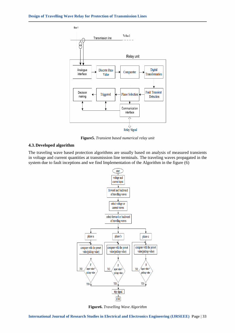
4.2. Proposed Protection Scheme
the decision making process in proposed transient based protection scheme and overall functionality
of the numerical relay model used in such scheme are explained. The model for a transient based
numerical relay unit installed at each terminal of the transmission line is proposed in Figure 5.
Design of Travelling Wave Relay for Protection of Transmission Lines
International Journal of Research Studies in Electrical and Electronics Engineering (IJRSEEE) Page | 33
Figure5. Transient based numerical relay unit
4.3. Developed algorithm
The traveling wave based protection algorithms are usually based on analysis of measured transients
in voltage and current quantities at transmission line terminals. The traveling waves propagated in the
system due to fault inceptions and we find Implementation of the Algorithm in the figure (6)
Figure6. Travelling Wave Algorithm
Design of Travelling Wave Relay for Protection of Transmission Lines
International Journal of Research Studies in Electrical and Electronics Engineering (IJRSEEE) Page | 34
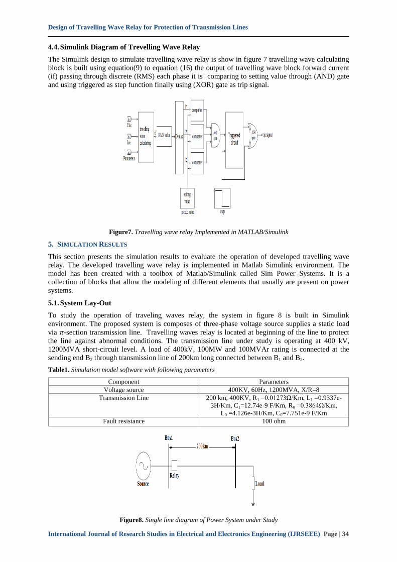
4.4. Simulink Diagram of Trevelling Wave Relay
The Simulink design to simulate travelling wave relay is show in figure 7 travelling wave calculating
block is built using equation(9) to equation (16) the output of travelling wave block forward current
(if) passing through discrete (RMS) each phase it is comparing to setting value through (AND) gate
and using triggered as step function finally using (XOR) gate as trip signal.
Figure7. Travelling wave relay Implemented in MATLAB/Simulink
5. SIMULATION RESULTS
This section presents the simulation results to evaluate the operation of developed travelling wave
relay. The developed travelling wave relay is implemented in Matlab Simulink environment. The
model has been created with a toolbox of Matlab/Simulink called Sim Power Systems. It is a
collection of blocks that allow the modeling of different elements that usually are present on power
systems.
5.1. System Lay-Out
To study the operation of traveling waves relay, the system in figure 8 is built in Simulink
environment. The proposed system is composes of three-phase voltage source supplies a static load
via 𝜋-section transmission line. Travelling waves relay is located at beginning of the line to protect
the line against abnormal conditions. The transmission line under study is operating at 400 kV,
1200MVA short-circuit level. A load of 400kV, 100MW and 100MVAr rating is connected at the
sending end B2 through transmission line of 200km long connected between B1 and B2.
Table1. Simulation model software with following parameters
Component Parameters
Voltage source 400KV, 60Hz, 1200MVA, X/R=8
Transmission Line 200 km, 400KV, R1 =0.01273Ω/Km, L1 =0.9337e-
3H/Km, C1=12.74e-9 F/Km, R0 =0.3864Ω/Km,
L0 =4.126e-3H/Km, C0=7.751e-9 F/Km
Fault resistance 100 ohm
Figure8. Single line diagram of Power System under Study

Design of Travelling Wave Relay for Protection of Transmission Lines
International Journal of Research Studies in Electrical and Electronics Engineering (IJRSEEE) Page | 35
5.2. Simulation Cases Results
The investigation of the travelling waves relay is carried out using Matlab Simulink environment.
The system in Fig.4.1 is modeled and simulated in the matlab software with the parameters given in
table 4.1.
The operational scenarios for traveling wave relay investigation include:
a) Operational during normal condition
b) Operational when symmetrical fault occur in the mid of transmission line
c) Operational when unsymmetrical fault occur in the mid of transmission line
5.2.1. Investigations during normal operation
The system in Figure 8 is operated in normal operation condition without any disturbance for period
of 0.2s. The results obtained simulation is shown in figure 9. As shown in figure 9a and figure 9b the
waveforms of the voltages and current are uniform during simulation period without any disturbances.
Also, the travelling wave components (forward and backward currents) calculated by the travelling
wave relay are uniform during simulation period as shown in figure 9c and figure 9d. The relay signal
sent to circuit break in this case is 1 which mean the breakers should close its contacts to allow the
current to flow in the system and supplies the static load.
Figure9a. System voltage wave during normal operation
Figure9b. System current wave during normal operation
Figure9c. Forward travelling wave during normal operation

Design of Travelling Wave Relay for Protection of Transmission Lines
International Journal of Research Studies in Electrical and Electronics Engineering (IJRSEEE) Page | 36
Figure9d. Backward travelling wave during normal operation
Figure9e. Relay signal during normal operation
5.2.2. Investigations during symmetrical fault
To demonstrate the ability of travelling wave relay during abnormal conditions, the system in figure 8
is subjected to three phase symmetrical fault in the middle of transmission line for duration of 0.1sec.
The results obtained during the simulation are shown in figure 10. As shown in figure 10a and figure
10b the waveforms of the voltages and current observe increases in current and decrease in voltage
when the fault occur and recover again when fault is cleared. The system is subjected to 6 times the
rated current for duration of 0.1s and this may destroy the entire system. If travelling wave relay is
used for protection of the line than the system is subjected to high current for duration of just 0.01 s
until the breaker eliminate the fault as shown in figure 10d. The travelling wave components (forward
and backward currents) calculated by the relay are ununiformed during simulation period as shown in
figure 10c and figure 10d which indicate occurring of abnormal condition and initiate the relay to
send trip signal to the breaker just after appearance of the fault as shown in figure 10e. The relay
signal to circuit break in this case is change from 1 to 0 at 0.05s which mean the breakers should open
its contact and clear the fault. Fig4.3f and Fig4.3g showed the voltage and current waveform after
operation of breaker. The voltage is subjected to transient decrease but recover to nominal values
while the current is fall to zero because the breakers are open.
Figure10a. System voltage wave during symmetrical fault

Design of Travelling Wave Relay for Protection of Transmission Lines
International Journal of Research Studies in Electrical and Electronics Engineering (IJRSEEE) Page | 37
Figure10b. System current wave during symmetrical fault
Figure10c. Forward travelling wave during symmetrical fault
Figure10d. Backward travelling wave during symmetrical fault
Figure10e. Relay signal during symmetrical fault clearing

Design of Travelling Wave Relay for Protection of Transmission Lines
International Journal of Research Studies in Electrical and Electronics Engineering (IJRSEEE) Page | 38
Figure10f. System voltage wave during symmetrical fault clearing
Figure10g. System current wave during symmetrical fault clearing
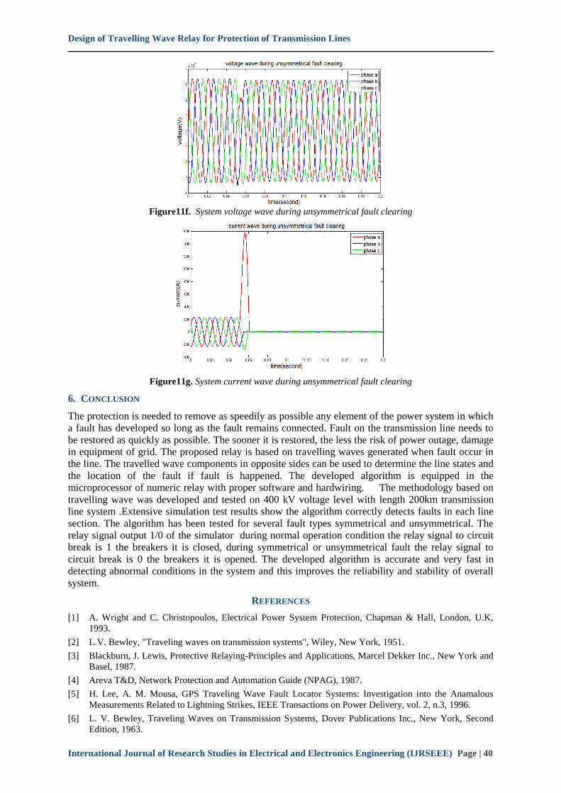
5.2.3. Investigations During Unsymmetrical Fault
The system in figure 8 is subjected to phase to ground unsymmetrical fault in the middle of
transmission line for duration of 0.1 sec. figure 11 show the simulation result during occurring of
phase to ground fault. As shown in figure 11a the voltage of phase a is decrease during fault period
and recover again when the fault is eliminated. Also phase a current is increase dramatically to about
6 times the rated value and this will destroy the system components if no proper protection is used as
shown in figure 11b. Again if travelling wave relay is used for protection of the line than the system is
subjected to high current for duration of just 0.01 s until the breaker eliminate the fault as shown in
figure 11g. The travelling wave components regarding phase a (forward and backward currents)
calculated by the relay are ununiformed during simulation period as shown in figure 11c and figure
11d which indicate occurring of abnormal condition and initiate the relay to send trip signal to the
breaker just after appearance of the fault as shown in figure 11e. The relay signal to circuit break in
this case is change from 1 to 0 at 0.05s which mean the breakers should open its contact and clear the
fault.
figure 11f and figure 11g showed the voltage and current waveform after operation of breaker. The
voltage is subjected to transient decrease but recover to nominal values while the current is fall to zero
because the breakers are open.
Figure11a. System voltage wave during unsymmetrical fault

Design of Travelling Wave Relay for Protection of Transmission Lines
International Journal of Research Studies in Electrical and Electronics Engineering (IJRSEEE) Page | 39
Figure11b. System current wave during unsymmetrical fault
Figure11c. Forward travelling wave during unsymmetrical fault
Figure11d. Backward travelling wave during unsymmetrical fault
Figure11e. Relay signal during unsymmetrical fault clearing
Design of Travelling Wave Relay for Protection of Transmission Lines
International Journal of Research Studies in Electrical and Electronics Engineering (IJRSEEE) Page | 40
Figure11f. System voltage wave during unsymmetrical fault clearing
Figure11g. System current wave during unsymmetrical fault clearing
6. CONCLUSION
The protection is needed to remove as speedily as possible any element of the power system in which
a fault has developed so long as the fault remains connected. Fault on the transmission line needs to
be restored as quickly as possible. The sooner it is restored, the less the risk of power outage, damage
in equipment of grid. The proposed relay is based on travelling waves generated when fault occur in
the line. The travelled wave components in opposite sides can be used to determine the line states and
the location of the fault if fault is happened. The developed algorithm is equipped in the
microprocessor of numeric relay with proper software and hardwiring. The methodology based on
travelling wave was developed and tested on 400 kV voltage level with length 200km transmission
line system .Extensive simulation test results show the algorithm correctly detects faults in each line
section. The algorithm has been tested for several fault types symmetrical and unsymmetrical. The
relay signal output 1/0 of the simulator during normal operation condition the relay signal to circuit
break is 1 the breakers it is closed, during symmetrical or unsymmetrical fault the relay signal to
circuit break is 0 the breakers it is opened. The developed algorithm is accurate and very fast in
detecting abnormal conditions in the system and this improves the reliability and stability of overall
system.
REFERENCES
[1] A. Wright and C. Christopoulos, Electrical Power System Protection, Chapman & Hall, London, U.K,
1993.
[2] L.V. Bewley, "Traveling waves on transmission systems", Wiley, New York, 1951.
[3] Blackburn, J. Lewis, Protective Relaying-Principles and Applications, Marcel Dekker Inc., New York and
Basel, 1987.
[4] Areva T&D, Network Protection and Automation Guide (NPAG), 1987.
[5] H. Lee, A. M. Mousa, GPS Traveling Wave Fault Locator Systems: Investigation into the Anamalous
Measurements Related to Lightning Strikes, IEEE Transactions on Power Delivery, vol. 2, n.3, 1996.
[6] L. V. Bewley, Traveling Waves on Transmission Systems, Dover Publications Inc., New York, Second
Edition, 1963.

Design of Travelling Wave Relay for Protection of Transmission Lines
International Journal of Research Studies in Electrical and Electronics Engineering (IJRSEEE) Page | 41
[7] M. Chamia and S. Liberman, Ultra High Speed Relay for EHV/UHV Transmission Lines - Development,
Design and Application, IEEE Transactions on Power Apparatus and Systems, Vol. PAS-97, No. 6,
Nov/Dec 1978, pp. 2104- 2112.
[8] M. S. Sachdev (Coordinator), IEEE Tutorial Course Text: Computer Relaying, Publication No. 79
EH0148-7-PWR, 1979.
[9] M. S. Sachdev (Coordinator), IEEE Tutorial Course: Advancements in Microprocessor Based Protection
and Communication, IEEE Power Engineering Society, NJ, 1997.
[10] P.A. Crossley and P.G. McLaren, Distance Protection Based on Traveling Waves, IEEE Transactions on
Power Apparatus and Systems, Vol. PAS-102, No. 9, September 1983, pp. 2971-2978.
[11] Juan M.Gers, Edward J.Holmes -Protection of Electricity Distribution Networks-2nd Edition -Institution
of Engineering and Technology-2005
[12] Gerhard Ziegler, Numerical Distance Protection, Public is Corporate Publishing, Erlangen, Siemens,
second edition, 2006, ISBN389578 266 1.
[13] Michael Faraday House- Six Hills Way, Stevenage Power System Protection -Institution of Electrical
Engineers-2005
[14] J. Duncan Glover, Mulukutlas. Sarma, Thomas J.Overbye- Power System Analysis And Design-Fifth
Edition- Publisher, Global Engineering-2012,2008 Cengage Learning
AUTHOR’S BIOGRAPHY
Modawy Adam Ali Abdalla, born in Elfasher-Sudan in 1987. Obtained his BSc. in
Electrical and Electronic Engineering (Power) at Nyala University. He Received his
MSc. in Electrical Engineering (Power) from Sudan University of Science and
Technology. Lecturer and head Department of Electrical and Electronic Engineering,
Faculty of Engineering Sciences, Nyala University. His field interest is in Renewable
Energy, Power System Protection, and Machines and Devices.
Citation: Modawy Adam Ali Abdalla et al.(2017). Design of Travelling Wave Relay for Protection of
Transmission Lines, International Journal of Research Studies in Electrical and Electronics Engineering
(IJRSEEE), 3(4), pp.29-41, DOI: http://dx.doi.org/10.20431/2454-9436.0304005.
Copyright: © 2017 Modawy Adam Ali Abdalla et al. This is an open-access article distributed under the
terms of the Creative Commons Attribution License, which permits unrestricted use, distribution, and
reproduction in any medium, provided the original author and source are credited