design standards - taurangaecontent.tauranga.govt.nz/data/idc/04_design_standards/04_design... ·...
TRANSCRIPT

DESIGN STANDARDS
IN THIS SECTION
§ DS-1 General Provisions§ DS-2 Streetscape§ DS-3 Reserves§ DS-4 Transportation Network§ DS-5 Stormwater§ DS-6 Wastewater§ DS-7 Water Supply§ DS-8 Public Lighting§ DS-9 Network Utilities§ DS-10 Natural Hazards and Earthworks§ DS-11 Road Zone Occupancy
DESIGN STANDARDSDS-1 GENERAL PROVISIONS
TABLE OF CONTENTS
DS-1.1 General ..............................................................................................................1
DS-1.2 Minimum Requirements ......................................................................................1
DS-1.3 Alternative Design ..............................................................................................1
DS-1.4 Sustainable Development ...................................................................................5
DS-1.5 Tauranga Waterfront and CBD Specific Design ................................................23
DS-1 GENERAL PROVISIONS
Updated 01/07/2014 Page 1
DS-1.1 General
Council is committed to providing quality streetscape, reserves and infrastructure whilebalancing operational and maintenance costs at a level of expenditure aligned with agreedcommunity affordability. In order to provide this, as well as consistency and certainty withinthe industry for design procedures, Council has outlined minimum design standards requiredfor streetscape, reserve and other infrastructure design.
Council encourages innovative design solutions that result in increased infrastructure quality,amenity value, maintenance and whole of life cost benefits.
DS-1.2 Minimum Requirements
a) Designs shall conform with the City Plan and IDC.
b) Designers shall use the design standards within the IDC as the minimum standard fordesigning and specifying streetscape, reserves or infrastructure for either:
i) The Council capital and operational works contracts or professional servicesagreements.
ii) Development works related to a Resource Consent regardless whether theinfrastructure will be vested in Council or remain in private ownership.
iii) Any other form of infrastructure development that will connect to Councils existinginfrastructure network.
c) Where designs relating to capital or operational works are not specifically covered by theIDC, then those designs shall be specific to the project or project element and follow therequirements of DS-1.3 Alternative Design.
d) Designers shall ensure that the latest operative version of the IDC is used. Designstandards may be added or deleted from the IDC through the review processes of theIDC. This information will be available online and Council will make all efforts to ensurethe lists are kept up to date.
e) The design standards shall be read in conjunction with all other sections of the IDC i.e.associated standards, statutes, bylaws, reference documents as referenced within theIDC. The designer shall also take into account any additional requirements made byCouncil to meet the specific needs of the development, catchment area or individualinfrastructure asset being considered.
f) Where designers find any error in the design standards or wish to have a new designstandards component added to the IDC, they shall advise the Manager: Asset andInfrastructure Planning who will process any such requests on behalf of Council.
g) All Resource Consent applications for subdivision or land use consent for developmentshall compile and submit to Council a Development Evaluation Report.
DS-1.3 Alternative Design
Council recognises the need to provide for consideration of innovative/alternative designs tomeet circumstances that are either:
a) Site specific constrained.

DS-1 GENERAL PROVISIONS
Page 2 Updated 01/07/2014
b) Within an existing built environment where design needs must take into consideration abuilt environment.
c) An innovative design or new technology.
d) In a circumstance where a comprehensive land use activity is being proposed andconsideration of a comprehensive planning, urban design and infrastructuredevelopment solution is required.
DS-1.3.1 Alternative Design Approval Proposals and Procedures
Application for alternative designs will be considered in the following manner:
a) DS-1.3.1.1 Brownfield Development.
b) DS-1.3.1.2 Greenfield Development.c) DS-1.3.1.3 Comprehensive Land Use.
DS-1.3.1.1 Brownfield Development
Council acknowledges that works designed within an existing BrownfieldDevelopment environment or specific design environments (Capital and OperationalWorks) may be unable (in some cases) to meet all design standards requirementsdue to existing urban development and servicing constraints or are not specificallycovered by the IDC. These designs, in the main, relate solely to development ofinfrastructure via Council's capital or operational works.
For these types of design, a designer shall identify the issues that limit the ability ofthe design to meet the minimum design standards and ensure the following mattersare considered:
a) The City Plan infrastructure performance standards.
b) The alternative design is undertaken in accordance with sound industry and riskmanagement practice.
c) The alternative design will develop infrastructure that delivers Council’sinfrastructure design life.
d) The alternative design will develop infrastructure that will not exceed currentlevels of service or whole of life costs. Where this is not possible, informationon the effects of this shall be supplied to Council.
e) Council’s Approved Material lists and Approved Drawings.
Brownfield Development or Specific Designs Procedures shall receive the agreementof the relevant asset manager for the alternative design.
DS-1.3.1.2 Greenfield Development
The nature of Greenfield Development sites means they do not possess the sameconstraints from a built environment that are present in the Brownfield Developmentenvironment. Therefore Greenfield Development is expected to be undertaken usingthe standard design basis with departure from the standard design occurring throughsite specific constraint, new technology or innovative design.

DS-1 GENERAL PROVISIONS
Updated 01/07/2014 Page 3
For these types of design, a designer shall identify the issues that limit the ability ofthe design to meet the standard design criteria and ensure the following matters areconsidered:
a) Display how the alternative design departs from the requirements of the CityPlan infrastructure performance standards and what is the effect of thedeparture.
b) The alternative design is undertaken in accordance with sound industry and riskmanagement practice.
c) The alternative design will develop infrastructure that will deliver Council’sagreed levels of service and infrastructure design life. Where this is not possible,information on the effects of this shall be supplied to Council.
d) The alternative design will develop infrastructure that will not exceed currentlevels of service or whole of life costs.
e) Council’s Approved Material lists and Approved Drawings.
Consultation with Council shall be undertaken prior to a full alternative design beingundertaken to ensure that the alternative design is one that Council considers willmeet its asset management and service delivery requirements.
Greenfield Development Alternative Designs Procedure
f) Application for approval of an alternative design is to be undertaken whenapplying for Development Works Approval or when applying for an amendmentto an existing Development Works Approval.
g) The alternative design application shall be appended to the application forDevelopment Works Approval and address the following:
i) An outline of the alternative design supported bydocumentation/calculations and drawings.
ii) How the alternative design addresses the matters listed in DS-1.3.1.2 a-e.
iii) The approval for the alternative design will be issued with theDevelopment Works Approval or amendment to the Development WorksApproval.
iv) Approval of an alternative design applies only to the development worksthe alternative design proposal covers. It does not approve the alternativefor general use on other development sites.
DS-1.3.1.3 Comprehensive Land Use
Changing demographics, market demand and affordability means that somedevelopments will require comprehensive design solutions incorporatinginfrastructure and landform development, urban design principles, land tenure needsetc.
For alternative comprehensive land use designs the designer shall, as a minimum,ensure the following matters are considered:
a) Identification of the infrastructure design elements proposed to be modified.

DS-1 GENERAL PROVISIONS
Page 4 Updated 01/07/2014
b) Delivery of the City Plan infrastructure performance standards.
c) Delivery of infrastructure to Council’s agreed levels of service, design life andwhole of life costs. Where this is not possible, information on the effects of thisshall be supplied to Council.
d) Provision of a concept master plan and design statement for the completedevelopment incorporating the following for discussion with Council:
i) Neighbourhood context.
ii) Site analysis.
iii) Preliminary site layout showing proposed lot boundaries, access ways forpedestrians, cycles and vehicles, private and communal open space,access points onto individual lots and potential building platforms.
iv) Landscape concept plan.
v) Consideration of efficient use of solar energy and other resources.
vi) Relationship to neighbourhood context.
vii) Density considerations.
viii) Development affordability.
ix) Housing typology.
x) Staging of development.
xi) Council’s approved material lists and approved drawings.
e) Comprehensive Land Use Designs Procedure
f) Comprehensive land use developments will be considered in the followingmanner:
i) The applicant will contact the Manager: Environmental Planning who willassign an Environmental Planner to manage the pre-applicationconsultation and Resource Consent process. A development engineer willalso be assigned to the proposal at the same time as the EnvironmentalPlanner to coordinate the infrastructure development portions of thedevelopment.
ii) The Environmental Planner will convene pre-application consultationmeetings between the applicant and Council staff (asset managers,development engineers, urban designers, policy planners etc). Theapplicant shall, at the meetings present information relating to theproposed comprehensive development including, as a minimum, thematters referenced in DS-1.3.1.3 a-d.
iii) Once all issues relating to the comprehensive development have beenworked through and agreed, the applicant shall complete any final designamendments and incorporate them into the application for ResourceConsent for the comprehensive development.
iv) The applicant will apply for Resource Consent based on the agreementsreached in the pre-application consultation. The application for ResourceConsent will include how the matters in DS-1.3.1.3 a-d have been met, aspat of the assessment of environmental effects.

DS-1 GENERAL PROVISIONS
Updated 01/07/2014 Page 5
v) The Resource Consent conditions will reflect the agreed developmentoutcomes which in turn will be reflected in the Development WorksApproval application.
The issuing of the Resource Consent for the comprehensive development is seen asapproval of the alternative design proposal. Thereafter existing business process willbe utilised.
DS-1.4 Sustainable Development
Our community is now aware that the management and development of our environmentneeds to utilise the best practices to ensure the long term well being of our environment.
Good resource management requires that the environment is managed, developed andoccupied, in a sustainable manner that ensures social, cultural, economic and environmentalinheritance of future generations.
Sustainability is defined as ‘development that meets the needs of the present generationwithout compromising the ability of future generations to meet their own needs’.
This is well reflected in the purpose of Local Government as set out in the Local GovernmentAct 2002, ‘to promote the social, economic, environmental, and cultural well-being ofcommunities, in the present and for the future’. It is also translated into other legislationwhich Council operates under including the Resource Management Act, Building Act, LandTransport Act etc.
Council adopted an approach to sustainability in October 2008. This requires all staff toconsider sustainability opportunities in work programmes across the organisation in anintegrated and coordinated way.
Sustainable development of Tauranga can be achieved through following the principles ofgood urban design, which considers the social, economic, environmental and culturalwell-being of communities.
DS-1.4.1 Development by Urban Design
Urban Design is the process of shaping urban settings. Urban Design is about urbanstructure, the relationship between spaces, roads and the density and range of activities.It involves the design of the public realm, the places and spaces between buildings,streets, parks and reserves to create the best possible public amenity in the mostsustainable way. Urban design is not just concerned with the physical environment butthe social, economic and cultural impact of that design. It requires input from manydifferent sectors and professions and includes the process of decision making as well asthe outcomes.
High quality urban environments are achieved through a comprehensive design process.Urban design considers the building blocks of development holistically to create the besturban form practicable. Traditional approaches to land development have emphasisedlot yield, engineering, and surveying requirements. These elements are important but theprimary objective of planning and urban design is to create liveable communities that aresafe, sustainable and rich in amenities for all users. New subdivisions must be designed

DS-1 GENERAL PROVISIONS
Page 6 Updated 01/07/2014
to meet today’s needs but also robust and adaptable enough to accommodate the needsof future generations.
DS-1.4.2 Core Design Principles
Key issues that influence quality of the built environment include:
a) Rationale underpins all good design. A clear design process that addresses all theinherent issues will produce a better subdivision than a solution based oncompliance with statutory requirements.
b) Context in which the subdivision is located, including the existing urban, landscapeand social setting. Context provides the parameters of the design
c) Layout should contribute to the local identity by acknowledging and reinforcing sitecharacteristics, surrounding environment, notable features, views, and identifiedregion-wide strategic initiatives.
d) Integrate subdivision with surrounding neighbourhoods, through the vehicle, cycleand pedestrian links and connected open space networks.
e) Connect vehicle, cycle and pedestrian routes to provide accessibility and choice inthe local area, to reduce travel distances, vehicle emissions, and support publictransport.
f) Access to public parks, open space, bus stops and community facilities needs to beconvenient, preferably within 400 -800m walk.
g) Reinforce existing local focal points and provide new nodes and focal points logicallyon the movement network.
h) Safe developments have lots fronting the road and public open spaces, allowinginformal surveillance of the public realm from dwellings.
i) Vary lot sizes and allow compatible uses to encourage a diverse community.
j) Open public spaces need to be safe, legible and cost effective to maintain andprovide for a variety of recreation uses.
k) Low impact approaches to managing the effects of development such as stormwaterrun-off helps maintain and protect the long-term environmental quality.
l) Protect and enhance ecological and heritage features to add value and uniquenessto the subdivision.
m) Consult stakeholders and affected parties throughout the design process beinginitiated. In particular in discussion with Tangata Whenua cultural landscape valuesshould be recognised and applied.
n) Strategic planning sets the framework for Tauranga City and thus parameters for anysubdivision.
DS-1.4.3 Neighbourhood Context and Site Analysis
In depth neighbourhood context and site analysis informs the design process. It isimportant to identify the opportunities available and any likely constraints on the siteearly. There will be an overriding rationale for every subdivision scheme, particularlywhere appropriate sustainable outcomes are identified. Involve the Council as early aspossible to help identify, provide information and refine this rationale to clarify objectives

DS-1 GENERAL PROVISIONS
Updated 01/07/2014 Page 7
and avoid misunderstandings and differences at later stages in the application process.Refer to DS-1.4.3 - Figure 1: Neighbourhood Context and Site Analysis.
Figure 1: Neighbourhood Context Analysis
DS-1.4.3.1 Neighbourhood Context Analysis
For thorough context analysis, research and record existing circumstances andpotential constraints and opportunities, the designer shall identify the following:
a) DS-1.4.3.2 Notable Features of the Neighbourhood.
b) DS-1.4.3.3 The Pattern of Development in the Neighbourhood.
c) DS-1.4.3.4 The Built Form, Scale, Amenities and Character of the SurroundingNeighbourhood.
d) DS-1.4.3.5 Site Analysis.

DS-1 GENERAL PROVISIONS
Page 8 Updated 01/07/2014
DS-1.4.3.2 Notable Features of the Neighbourhood
The following shall be considered during the design process:
a) Landform features such as promontories, dunes, wetlands, streams, rivers.
b) Significant views and aspect.
DS-1.4.3.3 The Pattern of Development in the Neighbourhood
The following shall be considered during the design process:
a) Movement networks for pedestrians, cyclists, drivers, public transport users.
b) Hierarchy of roads and connection to major routes.
c) Streetscape.
d) Distances to community facilities such as shops, schools, parks – 200m, 400mand 800m walkable routes.
e) Type of and facilities in open spaces and parks and linkages.
DS-1.4.3.4 The Built Form, Scale, Amenities and Character of theSurrounding Neighbourhood
The following shall be considered during the design process:
a) Existing and planned local centres, community facilities, public transport.
b) Existing and planned residential areas, housing types, parks and networks.
c) Surrounding subdivision lot size and street frontage dimension.
d) Existing housing types, scale and character.
e) Existing infrastructure and reticulated services (including overhead power lines),available connections and capacity.
DS-1.4.3.5 Site Analysis
A detailed analysis of the site helps determine the appropriate design of thesubdivision. The site analysis should be discussed with Tangata Whenua,neighbours, interested groups and Council staff to identify all of the relevant issues.
The following shall be considered during the design process:
a) Appropriate points of access onto the site.
b) Topography and natural features.
c) Soil type and stability.
d) Flora and fauna.
e) Access to sun on daily and yearly cycle.

DS-1 GENERAL PROVISIONS
Updated 01/07/2014 Page 9
f) Surface water and overland flow paths, waterways including ephemeral streamsand flooding risks.
g) Prevailing wind.
h) View shafts to natural and cultural features and other opportunities for outlook.
i) Previous and existing land use in regards to potential contamination.
j) Existing buildings and structures.
k) Heritage and cultural sites and features.l) Potential street connections to neighbouring sites.
m) Existing or potential cycle and pedestrian links.
n) Local sources of noise, dust, odour, vibration, light glare.o) Location and condition of on site infrastructure.
Access to and capacity of existing off-site services for new connections – power,water supply, sewerage, stormwater. Refer to DS-1.2.3.5 Figure 2: Site Analysis.
Figure 2: Site Analysis
DS-1 GENERAL PROVISIONS
Page 10 Updated 01/07/2014
DS-1.4.4 Design with the Environment
In the past development has often involved large scale earthworks removing naturalfeatures and piping water courses. With increasing community interest in environmentalsustainability, subdivisions are now being designed to take advantage of natural featureswithin a site to create a unique identity.
Public access to the coast and harbour is very important to the people living inTauranga. Development can significantly affect such environments through thedisturbance of natural erosion and accretion processes, loss of sand dunes, disturbanceof bird nesting areas and such like.
DS-1.4.4.1 Design Elements
The following shall be considered during the design process:
a) Preservation of dune systems, other coastal features and habitats.
b) Restoration of areas of degraded coast and harbour through suitable indigenousplantings, and, where necessary, protective fences.
c) Provision of public roads on the boundary with beaches, dune systems andharbour to maintain public access to them.
d) Incorporating public parks with any esplanade reserves to increase the amenityand utility of these spaces.
e) Provision of car parking and public amenities for visitors.
f) The use of restrictive covenants or other techniques that can prohibit pets insensitive habitat areas.
g) Incorporate streams and vegetation into the design of subdivisions through theprovision of open spaces where they can contribute recreational networksand/or maintain ecological values.
h) Connection of publicly accessible open spaces with streets, ensuring thesespaces are visible from adjacent sites and dwellings. This allows adjacent sitesand subdivision to capture some of the value of this open space.
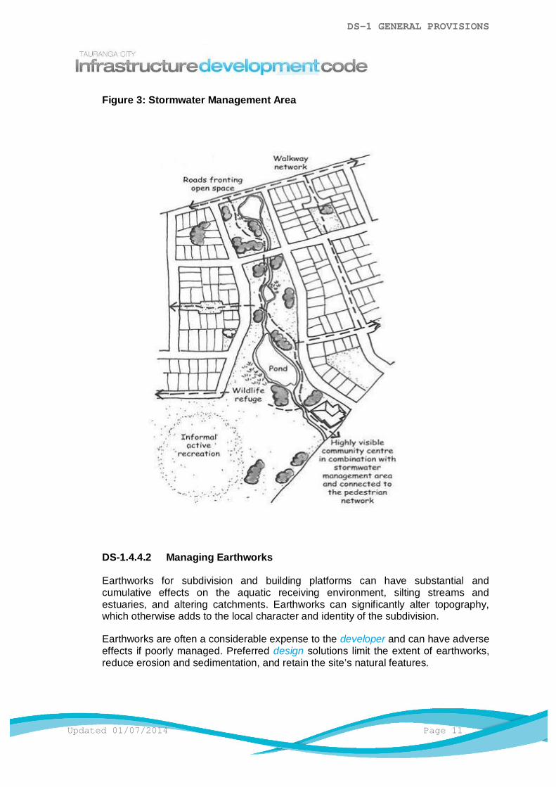
i) Retention and restoration of stream networks by planting banks in suitableindigenous species. Seek the assistance of an ecologist or talk with theCouncil to identify the most appropriate method to restore a stream. Refer toDS-1.4.4.1 Figure 3: Stormwater Management Area.
DS-1 GENERAL PROVISIONS
Updated 01/07/2014 Page 11
Figure 3: Stormwater Management Area
DS-1.4.4.2 Managing Earthworks
Earthworks for subdivision and building platforms can have substantial andcumulative effects on the aquatic receiving environment, silting streams andestuaries, and altering catchments. Earthworks can significantly alter topography,which otherwise adds to the local character and identity of the subdivision.
Earthworks are often a considerable expense to the developer and can have adverseeffects if poorly managed. Preferred design solutions limit the extent of earthworks,reduce erosion and sedimentation, and retain the site’s natural features.

DS-1 GENERAL PROVISIONS
Page 12 Updated 01/07/2014
DS-1.4.4.2.1 Design Elements
The following shall be considered during the design process:
a) Limiting the earthworks (volume and area). Avoid disturbing the naturallandform and steep slopes and thus adverse effects on aquaticenvironments. Excavate only the areas required for building platforms andaccess.
b) Designing the layout of roads and lots to work with the natural form of thesite.
c) Retaining the site’s topsoil, allowing the landscape to develop with newdwellings and avoiding the need to dispose large volumes of spoil.
DS-1.4.5 Movement and Access
As road networks can not be easily moved, changed, or removed, they are a majorinfluence on the success of the urban form. Movement networks impact on safety,community, and social contact, privacy, and areas of intensity that will support localshops or amenities.
DS-1.4.5.1 Connected Roads
A connected network of roads, lanes, and paths as opposed to a series or hierarchyof unconnected cul-de-sacs, increases accessibility for residents, allows for safer,more efficient movement of vehicular and non-vehicular traffic and enables moreefficient infrastructure provision. A hierarchy of an interconnected road system allowsan intuitive understanding of the area over the longer term, it also delays the need forsubstantial arterial route widening to manage poorly distributed peak traffic flows.
While subdivision applications are submitted on a site by site basis, there needs tobe consideration of future connections to ensure the neighbourhood and futuredevelopments are integrated and accessible. This includes the provision of roads,footpaths, and cycleways, open space links and community facilities.
DS-1.4.5.1.1 Design Elements
The following shall be considered during the design process:
a) Provision of a road layout (including cycleways and walkways) with as manylinks to adjacent sites and surrounding roads to create a choice of routes andtransport modes. Collaborate with adjacent landowners.
b) Design a road, cycle and pedestrian way which links bus stops, shops,schools, employment, parks and other amenities in the way people logicallyseek to move through a space.
c) Connection of roads forming urban blocks, less than 150m in length and onlytwo sites deep, are better than a large number of cul-de sacs and fewthrough roads.
d) Cul-de-sacs are only appropriate when they are short, or where thetopography is too steep to allow a safe connection. Provide pedestrian/cycle
DS-1 GENERAL PROVISIONS
Updated 01/07/2014 Page 13
links, at least 6.0m wide, from the cul-de-sac head to an adjacent road orpark.
e) Private right-of-ways should only be used to reach small pockets of land thatare inaccessible from a road.
DS-1.4.5.2 Road, Block and Lot Design
The layout of urban blocks, their size and length is important in maintaining awalkable neighbourhood. Blocks that are too deep or long limit the number ofconnected routes within a neighbourhood and increase the distances residents needto travel to services and amenities. This lowers the feasibility of walking to places,and can add unnecessary vehicle kilometres travelled.
The orientation of roads and blocks should also ensure that lots receive adequatesunlight in a manner that will allow dwellings and other uses to provide a public ‘front’to the road and a private ‘back’ for amenity.
Orientate lots to capitalise on views, take advantage of solar access and minimisethe discomfort of prevailing winds. The layout of lots should provide for a mix ofhousing types through varying lot sizes and densities. Smaller lots at higher densitiesshould be close to centres, public transport and facilities.
People wish to live in an environment where they feel safe and secure. Subdivisionsshould be carefully designed and managed so that the fear of crime and the actualincidence of crime are reduced. A conventional response has been the gatedsuburbs and solid high fences which can reduce safety through the isolation andscreening of crime targets.
Passive surveillance of public spaces is one effective deterrent. Achieving thisrequires careful consideration of subdivision layout, and elements of residentialenvironment such as lighting, fences, planting and the relationship of houses to theroad and public spaces.
DS-1.4.5.2.1 Design Elements
The following shall be considered during the design process:
a) Aligning roads north/south and lots east/west wherever possible to maximisesunlight to sites.
b) Providing lots with sufficient area and dimensions to meet user needs. Ideallylots should be rectangular in shape.
c) Arranging lots along the road fronts. Avoid developing rear lots within a block.
d) Designing urban blocks for lots to have fronts facing fronts and backs facingbacks.
e) Locating lots to ensure sheltered microclimates can be delivered.
f) Allow south facing lots north facing backyards for outdoor living.

DS-1 GENERAL PROVISIONS
Page 14 Updated 01/07/2014
g) Make north facing residential lots wider to allow private outdoor living to theside of the dwelling, without conflicting with the need for passive surveillanceof the street.
h) Limit the size and length of urban blocks to increase the choice of routes, andallowing for increases in residential density close to town centres.
i) Avoid rear lots as they generate public/private conflict along the sides of frontand adjacent lots, and don’t provide connection to the road, community, oramenities.
j) Ensure a variety of different sized lots.
k) Incorporate the principles of Crime Prevention through Environmental Design(CPTED) in the development of subdivisions. Refer to DS-1.4.5.2.1 Figure 4:Lot Orientation.
Figure 4: Lot Orientation
DS-1.4.5.3 Road Design
Carriageways, berms, cycleways, footpaths, car-parks, and sometimes stormwaterinfrastructure all need to share the road reserve. Road widths, cycleways, footpathstyles and materials, berm location and width, in combination with tree planting canall be used creatively to deliver variety, interest and identity into neighbourhoods.
In residential areas well designed, connected local roads can provide slow traffic andsafety for children playing near the road - whilst promoting accessibility. Road
DS-1 GENERAL PROVISIONS
Updated 01/07/2014 Page 15
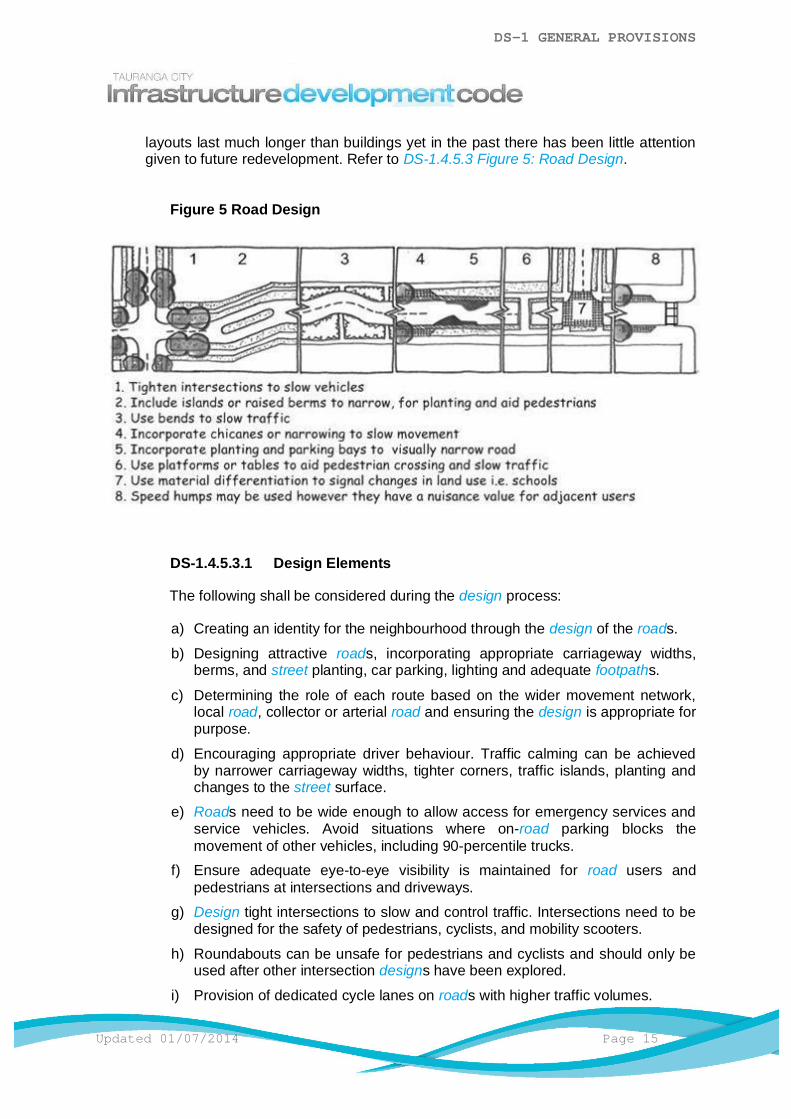
layouts last much longer than buildings yet in the past there has been little attentiongiven to future redevelopment. Refer to DS-1.4.5.3 Figure 5: Road Design.
Figure 5 Road Design
DS-1.4.5.3.1 Design Elements
The following shall be considered during the design process:
a) Creating an identity for the neighbourhood through the design of the roads.
b) Designing attractive roads, incorporating appropriate carriageway widths,berms, and street planting, car parking, lighting and adequate footpaths.
c) Determining the role of each route based on the wider movement network,local road, collector or arterial road and ensuring the design is appropriate forpurpose.
d) Encouraging appropriate driver behaviour. Traffic calming can be achievedby narrower carriageway widths, tighter corners, traffic islands, planting andchanges to the street surface.
e) Roads need to be wide enough to allow access for emergency services andservice vehicles. Avoid situations where on-road parking blocks themovement of other vehicles, including 90-percentile trucks.
f) Ensure adequate eye-to-eye visibility is maintained for road users andpedestrians at intersections and driveways.
g) Design tight intersections to slow and control traffic. Intersections need to bedesigned for the safety of pedestrians, cyclists, and mobility scooters.
h) Roundabouts can be unsafe for pedestrians and cyclists and should only beused after other intersection designs have been explored.
i) Provision of dedicated cycle lanes on roads with higher traffic volumes.
DS-1 GENERAL PROVISIONS
Page 16 Updated 01/07/2014
j) Footpaths should be provided on both sides of the road unless a clear caseto the contrary exists.
k) Provision of providing rear lanes or slip lanes for vehicle access and parkingadjacent to heavy traffic routes, avoiding multiple driveways compromisingthe road’s function.
l) Provision of bus-stops on public transport routes and ensure that these stopsare overlooked by adjacent housing and other activities. Ensure that every lotis within 10 minutes walk of a bus stop and adjust the road network to providedirect routes.
m) Avoid private ways, rights of ways, or common access ways as they do notprovide the same amenity or privacy as roads.
DS-1.4.5.4 Traffic Calming
The efficient through movement of traffic needs to be reconciled with the need toprovide safe, high-amenity settings for residential areas.
DS-1.4.5.4.1 Design Elements
The following shall be considered during the design process:
a) Creation of safer streets. Mark different mode space with different materials.Use colour and material to make vehicular carriageway, footpaths and cycleways, parking bays and manoeuvring areas clearly visible.
b) Tighten intersection corners to ensure slower vehicle movements.
c) Road islands and extended berms aid pedestrian crossing, slow vehicles andcan be planted.
d) Avoid long straight local residential roads by using the road reservation widthfor shifts in the carriageway to slow traffic.
e) Incorporate chicanes or ‘chokers’ at key points to slow movement. Mountablekerbs can allow wider radii for large and emergency service vehicles.
f) Incorporate planting in parking bays to help make the carriageway seempsychologically narrower to drivers.
g) Use tables i.e. large, flat speed humps, to aid pedestrian crossing withoutrelying on formal crossing points.
h) Raise intersections in a different material to make more prominent and slowvehicles.
i) Speed bumps (up to 1.0m wide) or humps (essentially a long speed bump upto 4.Om + wide) can manage vehicle speeds. However due to the nuisancethey can create for adjacent users they should be considered as the leastdesirable form of intervention.
DS-1.4.5.5 On Road Car Parking
On road parking needs to be provided in a manner that maintains the amenity of thestreet.
DS-1 GENERAL PROVISIONS
Updated 01/07/2014 Page 17
DS-1.4.5.5.1 Design Elements
The following shall be considered during the design process:
a) Parallel kerbside parking evenly distributed throughout the subdivision isgood for visitor and resident parking.
b) Parking can be concentrated alongside parks to promote public use arid torelieve parking in nearby residential roads.
c) Use different parking bay materials to contrast with traffic lanes and make thestreetscape more appealing (as well as reducing vehicle speeds).
d) Driveways need to avoid parking bays.
e) Be aware of facilities that may have parking congestion issues at particulartimes.
f) Ensure street-trees have sufficient area to grow.
DS-1.4.6 Access to Community Services and Facilities
Residents require access to community facilities in order to meet their daily needs, andto participate in community activities. New subdivisions should provide clear direct linksto existing community services and facilities such as shops, schools, libraries, and healthfacilities. Facilities within walking distance can encourage residents to walk and use thecar less. This also allows non-drivers (children, the elderly, and those with disabilities) toindependently access community facilities.
Opportunities for residents to work locally will minimise travel distances and avoidcreating dormitory suburbs, as well as strengthen the economic and general vitality oftown centres.
DS-1.4.6.1 Design Elements
The following shall be considered during the design process:
a) Taking advantage of strategic locations adjacent to collector roads andintersections to develop local centres containing retail, services, employment,education, and community facilities.
b) Look to stimulate the provision of new facilities if none exist in the localenvironment.
DS-1.4.6.2 Open Spaces
Parks and open spaces are important elements of a neighbourhood. They providespace for activity and social contact, and are a contrast to the urban built form.
Parks provide a protected outlook for surrounding sites that if marketed well can addvalue through their guarantee of never being built out.
DS-1 GENERAL PROVISIONS
Page 18 Updated 01/07/2014
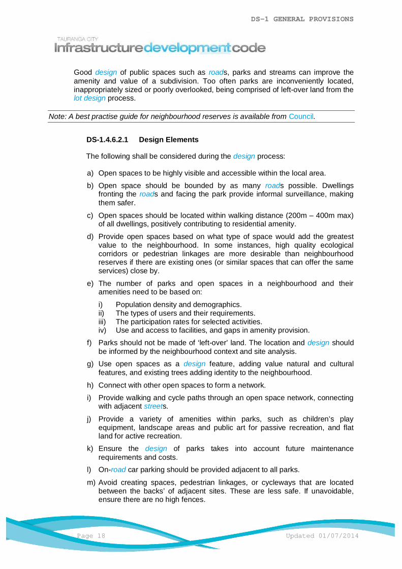
Good design of public spaces such as roads, parks and streams can improve theamenity and value of a subdivision. Too often parks are inconveniently located,inappropriately sized or poorly overlooked, being comprised of left-over land from thelot design process.
Note: A best practise guide for neighbourhood reserves is available from Council.
DS-1.4.6.2.1 Design Elements
The following shall be considered during the design process:
a) Open spaces to be highly visible and accessible within the local area.
b) Open space should be bounded by as many roads possible. Dwellingsfronting the roads and facing the park provide informal surveillance, makingthem safer.
c) Open spaces should be located within walking distance (200m – 400m max)of all dwellings, positively contributing to residential amenity.
d) Provide open spaces based on what type of space would add the greatestvalue to the neighbourhood. In some instances, high quality ecologicalcorridors or pedestrian linkages are more desirable than neighbourhoodreserves if there are existing ones (or similar spaces that can offer the sameservices) close by.
e) The number of parks and open spaces in a neighbourhood and theiramenities need to be based on:
i) Population density and demographics.ii) The types of users and their requirements.iii) The participation rates for selected activities.iv) Use and access to facilities, and gaps in amenity provision.
f) Parks should not be made of ‘left-over’ land. The location and design shouldbe informed by the neighbourhood context and site analysis.
g) Use open spaces as a design feature, adding value natural and culturalfeatures, and existing trees adding identity to the neighbourhood.
h) Connect with other open spaces to form a network.
i) Provide walking and cycle paths through an open space network, connectingwith adjacent streets.
j) Provide a variety of amenities within parks, such as children’s playequipment, landscape areas and public art for passive recreation, and flatland for active recreation.
k) Ensure the design of parks takes into account future maintenancerequirements and costs.
l) On-road car parking should be provided adjacent to all parks.
m) Avoid creating spaces, pedestrian linkages, or cycleways that are locatedbetween the backs’ of adjacent sites. These are less safe. If unavoidable,ensure there are no high fences.

DS-1 GENERAL PROVISIONS
Updated 01/07/2014 Page 19
DS-1.4.6.3 Streetscape
The standard and appearance of street trees, plantings, paving, walls, fences, seatsand other structures play an important role in establishing the identity, quality,amenity, visual interest and character of a subdivision.
DS-1.4.6.3.1 Design Elements
The following shall be considered during the design process:
a) The streetscape should reflect the functions and characteristics of the roadtype in the network.
b) Incorporate existing significant vegetation where possible.
c) Ensure that the streetscape is sensitive to the character of theneighbourhood and preserves important views and vistas.
d) Provision of street trees. Avoid locating trees where they are likely to interferewith services, driveways and parking bays or be removed at a future date.
e) Take advantage of opportunities for groups of trees in appropriately-sizedpockets, and in corners created by the layout of lots.
f) Provide adequate grass berms or tree-pits to allow the trees to grow tomaturity. This may mean locating the street tree adjacent to a lot boundary.
g) Ensure the species is well suited to local conditions, being tolerant of wind,frosts, droughts, wet conditions and salt spray, and are easily maintained.
h) Select tree species that will grow to an appropriate height and canopy for thelocation, width of street, and for ongoing maintenance. On wider streets, uselarger trees, either in lines or groves. Avoid shrub species that blocksightlines of pedestrians and vehicles.
i) Use locally sourced indigenous trees to enhance biodiversity.
j) Hard-landscape (paving areas etc.) to be robust and designed such that itdoes not place an onerous long-term maintenance liability on the Council.
k) Coordinate planting works with seasonal preferences for plant establishment,and subdivision development completion.
l) Council parks staff, landscape architect and arborists are available to provideinformation and guidance on streetscape opportunities during design.
DS-1.4.7 Public Transport Network - Bus Routes
Bus route planning for new or extended bus services will require sub-regional ordevelopment area planning. Tauranga City Council, Western Bay of Plenty DistrictCouncil and Bay of Plenty Regional Council will assist developers to incorporate widerbus networks into their proposals.
DS-1.4.7.1 Design Elements
The following shall be considered during the design process:

DS-1 GENERAL PROVISIONS
Page 20 Updated 01/07/2014
a) Most bus routes should be located on arterial or collector roads.
b) 90% of dwellings should be located within 500m safe walking distance of anexisting or potential bus route.
c) Avoid ‘dead running’ within or between subdivisions where there are nodwellings nor patronage generating uses fronting the bus route.
d) All intersections should accommodate bus turning movements.
e) Where development could cause significant congestion delays, bus prioritymeasures such as traffic signal priority and bus lanes should be implemented,particularly on routes receiving heavy bus flow.
f) Bus routes should access major activity centres from several direction. Refer toDS-1.4.7.1 Figure 6: Bus Stop - Typical Bus Route Layout.
Figure 6: Bus Stop - Typical Bus Route Layout
DS-1.4.7.2 Bus Stop Location - Design Elements
The following shall be considered during the design process:
a) Spacing between stops should be at a maximum of 400 - 500 m along the route,dependent on proximity of side roads or pedestrian links.
b) Locate adjacent to major trip generators such as hospitals, schools commercialcentres and elderly persons housing.
c) Locate with regard to pedestrian routes, subways, bridges, school crossingdesire lines etc. to maximise bus stop catchments.
d) Do not locate stops on crests of hills or on the inside of curves due to poor sightlines.
e) Avoid stops at the bottom of hills because of the hazards associated with heavybraking.
f) Bus stop facilities should not be located where they will unreasonably preventaccess to adjacent land with frontage to the road.
DS-1 GENERAL PROVISIONS
Updated 01/07/2014 Page 21
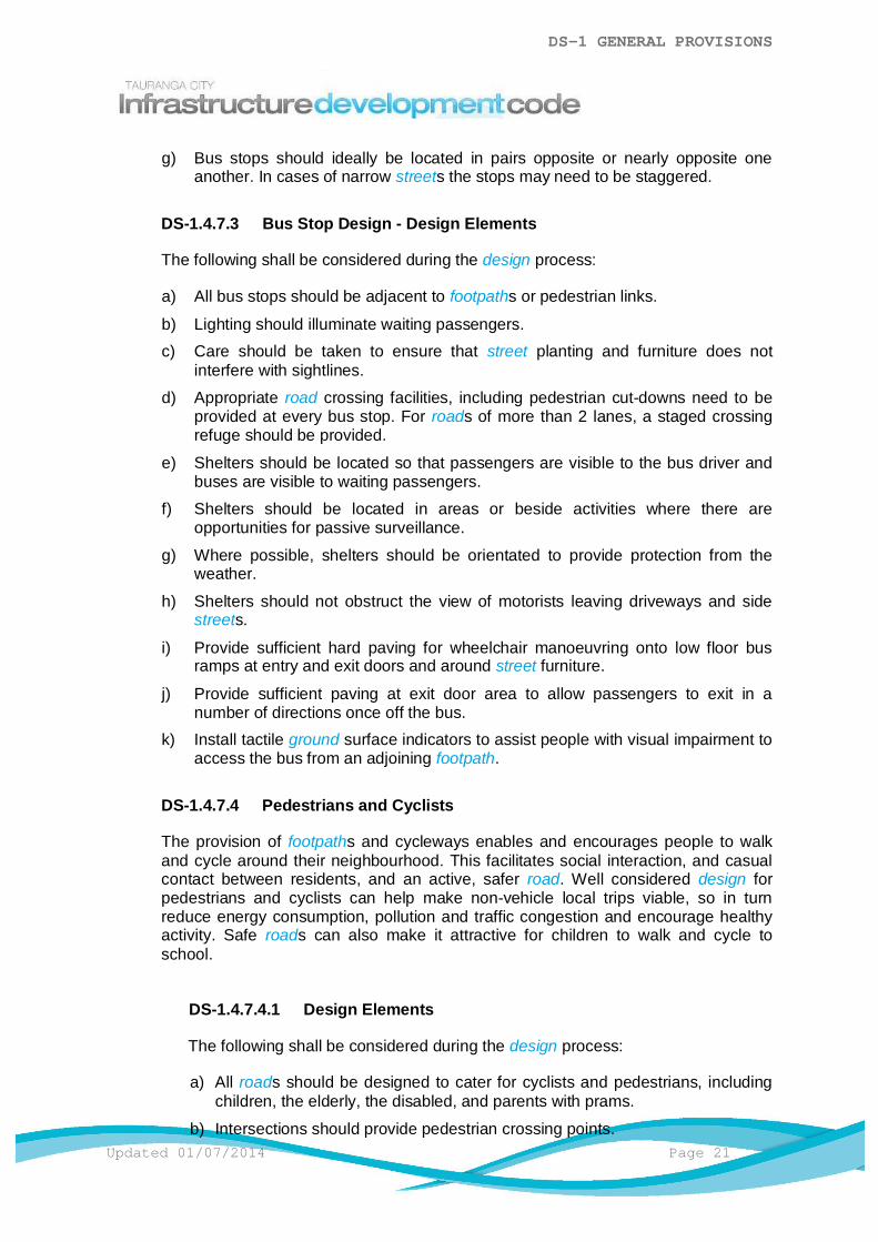
g) Bus stops should ideally be located in pairs opposite or nearly opposite oneanother. In cases of narrow streets the stops may need to be staggered.
DS-1.4.7.3 Bus Stop Design - Design Elements
The following shall be considered during the design process:
a) All bus stops should be adjacent to footpaths or pedestrian links.
b) Lighting should illuminate waiting passengers.c) Care should be taken to ensure that street planting and furniture does not
interfere with sightlines.
d) Appropriate road crossing facilities, including pedestrian cut-downs need to beprovided at every bus stop. For roads of more than 2 lanes, a staged crossingrefuge should be provided.
e) Shelters should be located so that passengers are visible to the bus driver andbuses are visible to waiting passengers.
f) Shelters should be located in areas or beside activities where there areopportunities for passive surveillance.
g) Where possible, shelters should be orientated to provide protection from theweather.
h) Shelters should not obstruct the view of motorists leaving driveways and sidestreets.
i) Provide sufficient hard paving for wheelchair manoeuvring onto low floor busramps at entry and exit doors and around street furniture.
j) Provide sufficient paving at exit door area to allow passengers to exit in anumber of directions once off the bus.
k) Install tactile ground surface indicators to assist people with visual impairment toaccess the bus from an adjoining footpath.
DS-1.4.7.4 Pedestrians and Cyclists
The provision of footpaths and cycleways enables and encourages people to walkand cycle around their neighbourhood. This facilitates social interaction, and casualcontact between residents, and an active, safer road. Well considered design forpedestrians and cyclists can help make non-vehicle local trips viable, so in turnreduce energy consumption, pollution and traffic congestion and encourage healthyactivity. Safe roads can also make it attractive for children to walk and cycle toschool.
DS-1.4.7.4.1 Design Elements
The following shall be considered during the design process:
a) All roads should be designed to cater for cyclists and pedestrians, includingchildren, the elderly, the disabled, and parents with prams.
b) Intersections should provide pedestrian crossing points.
DS-1 GENERAL PROVISIONS
Page 22 Updated 01/07/2014
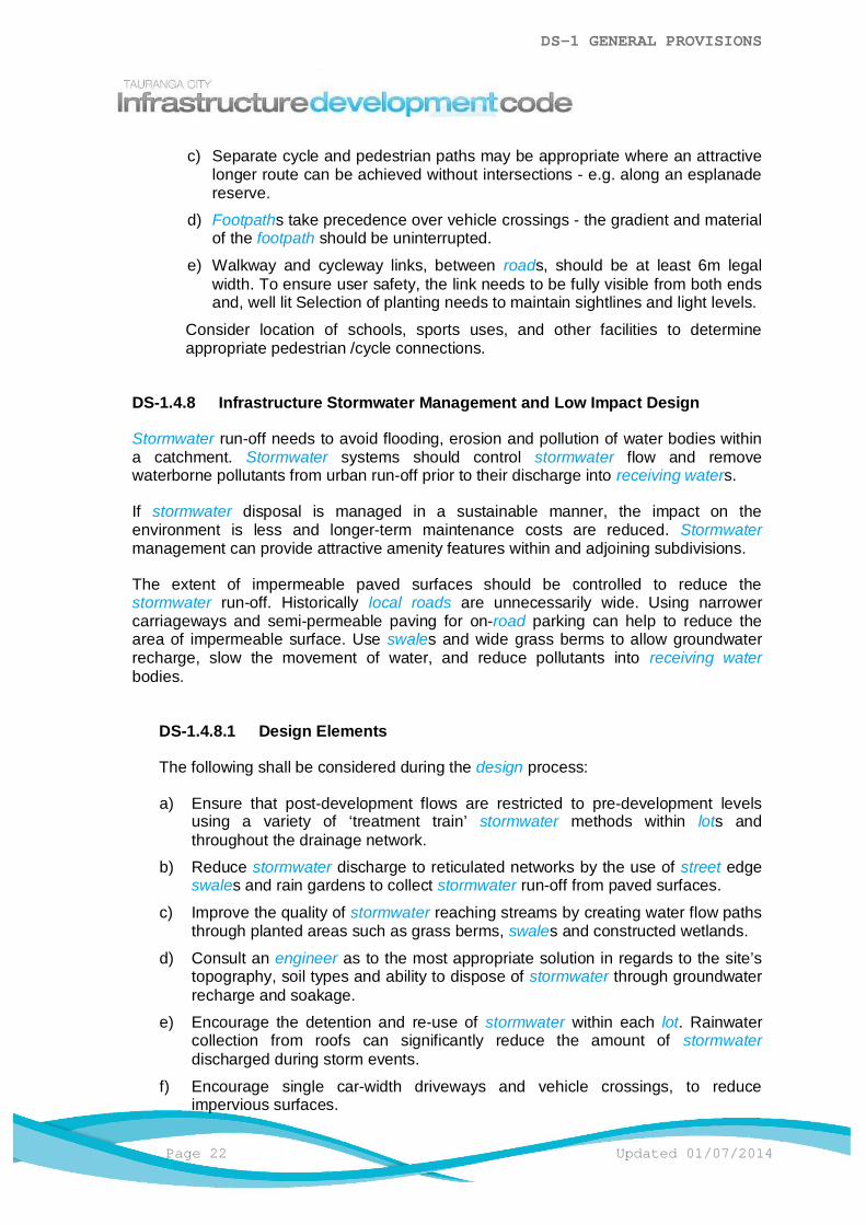
c) Separate cycle and pedestrian paths may be appropriate where an attractivelonger route can be achieved without intersections - e.g. along an esplanadereserve.
d) Footpaths take precedence over vehicle crossings - the gradient and materialof the footpath should be uninterrupted.
e) Walkway and cycleway links, between roads, should be at least 6m legalwidth. To ensure user safety, the link needs to be fully visible from both endsand, well lit Selection of planting needs to maintain sightlines and light levels.
Consider location of schools, sports uses, and other facilities to determineappropriate pedestrian /cycle connections.
DS-1.4.8 Infrastructure Stormwater Management and Low Impact Design
Stormwater run-off needs to avoid flooding, erosion and pollution of water bodies withina catchment. Stormwater systems should control stormwater flow and removewaterborne pollutants from urban run-off prior to their discharge into receiving waters.
If stormwater disposal is managed in a sustainable manner, the impact on theenvironment is less and longer-term maintenance costs are reduced. Stormwatermanagement can provide attractive amenity features within and adjoining subdivisions.
The extent of impermeable paved surfaces should be controlled to reduce thestormwater run-off. Historically local roads are unnecessarily wide. Using narrowercarriageways and semi-permeable paving for on-road parking can help to reduce thearea of impermeable surface. Use swales and wide grass berms to allow groundwaterrecharge, slow the movement of water, and reduce pollutants into receiving waterbodies.
DS-1.4.8.1 Design Elements
The following shall be considered during the design process:
a) Ensure that post-development flows are restricted to pre-development levelsusing a variety of ‘treatment train’ stormwater methods within lots andthroughout the drainage network.
b) Reduce stormwater discharge to reticulated networks by the use of street edgeswales and rain gardens to collect stormwater run-off from paved surfaces.
c) Improve the quality of stormwater reaching streams by creating water flow pathsthrough planted areas such as grass berms, swales and constructed wetlands.
d) Consult an engineer as to the most appropriate solution in regards to the site’stopography, soil types and ability to dispose of stormwater through groundwaterrecharge and soakage.
e) Encourage the detention and re-use of stormwater within each lot. Rainwatercollection from roofs can significantly reduce the amount of stormwaterdischarged during storm events.
f) Encourage single car-width driveways and vehicle crossings, to reduceimpervious surfaces.

DS-1 GENERAL PROVISIONS
Updated 01/07/2014 Page 23
g) Design wetlands and ponds to avoid water quality problems. Select vegetationto avoid choking choke waterways.
h) Use permeable hard surfaces wherever possible.
DS-1.4.9 Putting it all Together
For each subdivision there will be different parameters for the design rationale based ona range of variables such as the context, climatic conditions, site opportunities andconstraints. As such the weighting of the core design principles will also vary. Theintention of this section is to ensure that each principle is considered as part of thedesign rationale and that any subdivision design reflects the best combination of theseas appropriate to the site and its location, irrespective of the conventional developmentparadigm.
DS-1.5 Tauranga Waterfront and CBD Specific Design
The Tauranga City Waterfront is an increasingly important part of Tauranga City's openspace. The most recent master plan of the Waterfront was developed in 2008 to provide anoverall framework for the scale of development and to identify the types of facilities andactivities that can be accommodated.
The Master Plan identifies four different character precincts in the Waterfront and CBD area.These are outlined as an appendix to Council's City Centre Strategy. Each precinct has adifferent character generated from the localised mix of history, commence, art andrecreation. The creation of distinct, local variations within the different precincts will create alevel of diversity and richness in the city.
DS-1.5.1 Character Precincts
The Waterfront and CBD have been divided into the following four character precincts:
a) Historic Precinct.
b) Dive Crescent Precinct.
c) Recreational Precinct.
d) City Precinct.
These can be found in SD-1 Apx A.2 Tauranga Central Business District (CBD series).
DS-1.5.2 Infrastructural Components
To reinforce the distinct character of each of the precincts, streetscape elements havebeen developed as a related suite in terms of design, proportion, materials and finish tocreate a seamless fit between the different precincts and to provide a coherent andconsistent identity for Tauranga. These elements have also been selected with regardto the existing distinctive paving and suite of furniture used in the developed areas of thecity centre. These elements are to be found in the IDC.
The intention is that these urban elements will:
DS-1 GENERAL PROVISIONS
Page 24 Updated 01/07/2014
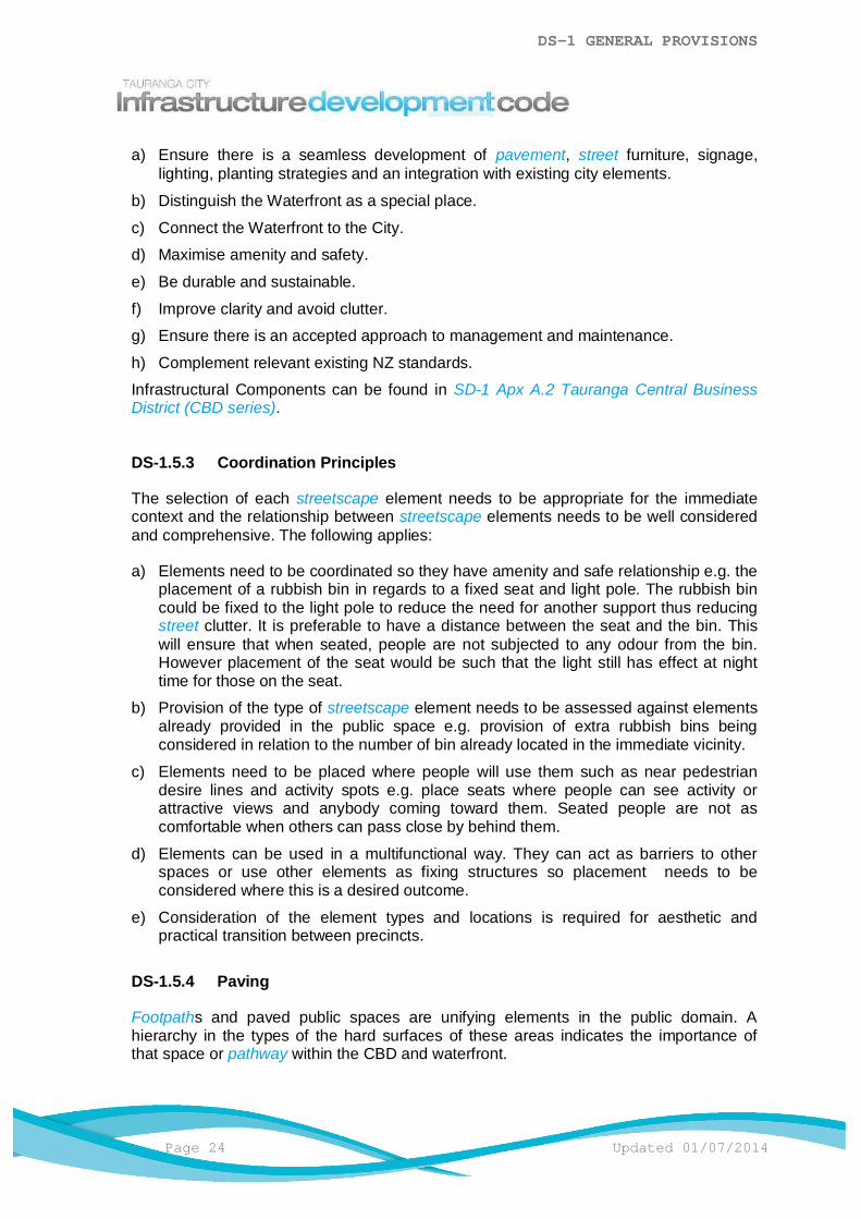
a) Ensure there is a seamless development of pavement, street furniture, signage,lighting, planting strategies and an integration with existing city elements.
b) Distinguish the Waterfront as a special place.
c) Connect the Waterfront to the City.
d) Maximise amenity and safety.
e) Be durable and sustainable.
f) Improve clarity and avoid clutter.
g) Ensure there is an accepted approach to management and maintenance.
h) Complement relevant existing NZ standards.
Infrastructural Components can be found in SD-1 Apx A.2 Tauranga Central BusinessDistrict (CBD series).
DS-1.5.3 Coordination Principles
The selection of each streetscape element needs to be appropriate for the immediatecontext and the relationship between streetscape elements needs to be well consideredand comprehensive. The following applies:
a) Elements need to be coordinated so they have amenity and safe relationship e.g. theplacement of a rubbish bin in regards to a fixed seat and light pole. The rubbish bincould be fixed to the light pole to reduce the need for another support thus reducingstreet clutter. It is preferable to have a distance between the seat and the bin. Thiswill ensure that when seated, people are not subjected to any odour from the bin.However placement of the seat would be such that the light still has effect at nighttime for those on the seat.
b) Provision of the type of streetscape element needs to be assessed against elementsalready provided in the public space e.g. provision of extra rubbish bins beingconsidered in relation to the number of bin already located in the immediate vicinity.
c) Elements need to be placed where people will use them such as near pedestriandesire lines and activity spots e.g. place seats where people can see activity orattractive views and anybody coming toward them. Seated people are not ascomfortable when others can pass close by behind them.
d) Elements can be used in a multifunctional way. They can act as barriers to otherspaces or use other elements as fixing structures so placement needs to beconsidered where this is a desired outcome.
e) Consideration of the element types and locations is required for aesthetic andpractical transition between precincts.
DS-1.5.4 Paving
Footpaths and paved public spaces are unifying elements in the public domain. Ahierarchy in the types of the hard surfaces of these areas indicates the importance ofthat space or pathway within the CBD and waterfront.
DS-1 GENERAL PROVISIONS
Updated 01/07/2014 Page 25
Pedestrian pathways need to take precedence over vehicle crossings at pedestriancrossings to prioritise people in the city environment. Footpaths need to be comfortable,wide and suitable for universal use.
Paving needs to be unified by a harmonious colour and texture palette. It also needs tobe easily maintained and strong enough for a maintenance vehicle. Where it coversunderground services, paving needs to be removable. Where it is near trees, pavingneeds to be permeable.
Ensure no streetscape elements project into accessible routes or pedestrian pathways.
DS-1.5.4.1 Paving Selection
At the waters edge, use large pieces of large sized hardwood in reference to themaritime setting. Further inland, use insitu concrete in the recreation areas and largeformat pavers in streetscapes. Both give a sense of scale and simplicity.
In special areas and event spaces on the waterfront, unbound aggregates such aslime chip gravel and grassed areas may be considered as suitable soft surfaces.Between existing and new surfaces, the transition zones can incorporate a simplemix of materials such as hotmix in a paved border.
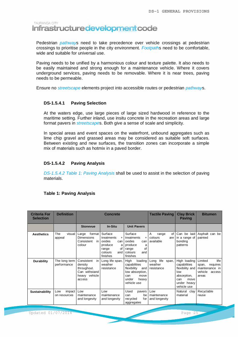
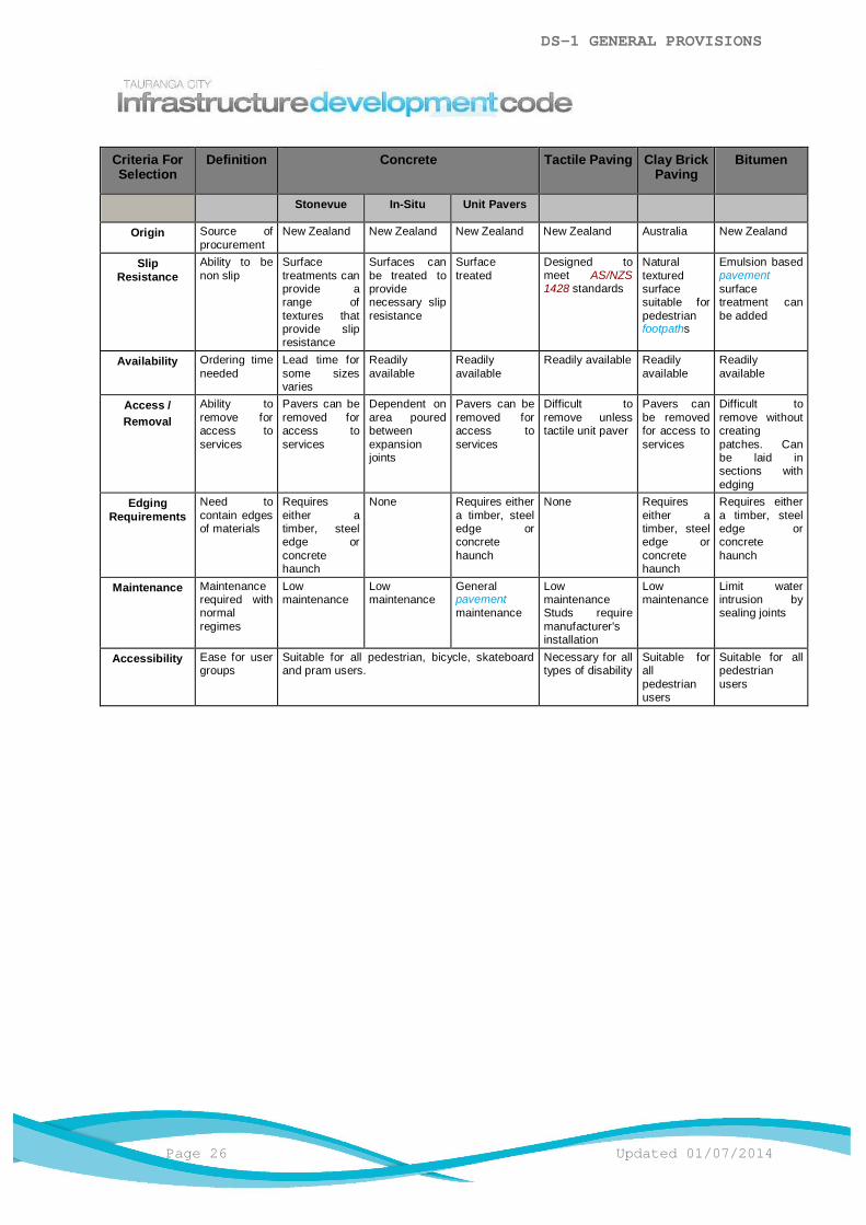
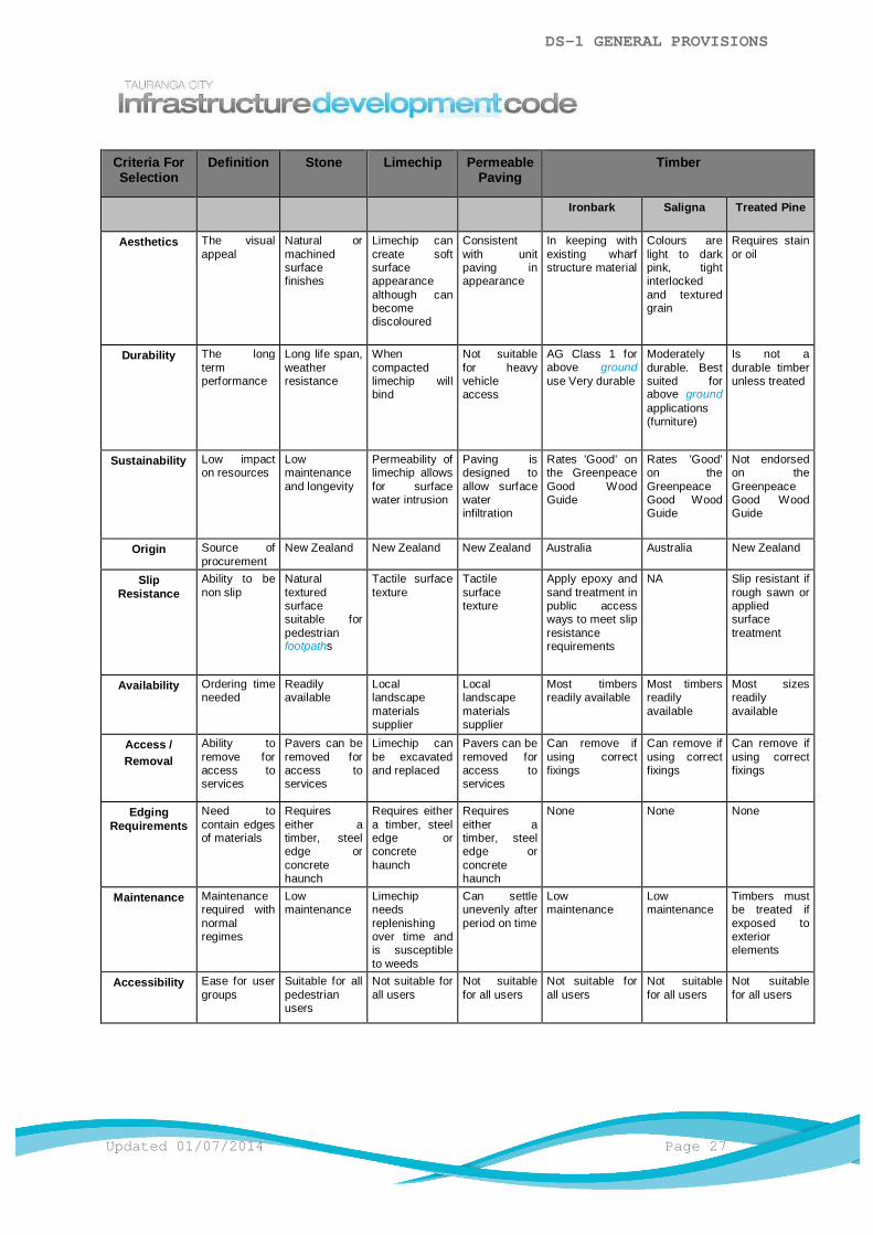
DS-1.5.4.2 Paving Analysis
DS-1.5.4.2 Table 1: Paving Analysis shall be used to assist in the selection of pavingmaterials.
Table 1: Paving Analysis
Criteria ForSelection
Definition Concrete Tactile Paving Clay BrickPaving
Bitumen
Stonevue In-Situ Unit Pavers
Aesthetics The visualappeal
Large formatDimensionsConsistent incolour
Surfacetreatments +oxides canproduce arange ofcolours andfinishes
Surfacetreatments +oxides canproduce arange ofcolours andfinishes
A range ofcolours areavailable
Can be laidin a range ofbondingpatterns
Asphalt can bepainted
Durability The long termperformance
Consistent indensitythroughout.Can withstandheavy vehicleaccess
Long life span,weatherresistance
High loadingcapabilitiesflexibility andlow absorption,can moveunder heavyvehicle use
Long life span,weatherresistance
High loadingcapabilitiesflexibility andlowabsorption,can moveunder heavyvehicle use
Limited lifespan, requiresmaintenance invehicle accessareas
Sustainability Low impacton resources
Lowmaintenanceand longevity
Lowmaintenanceand longevity
Used paverscan berecycled foraggregates
Lowmaintenanceand longevity
Natural claymaterial
Recyclablereuse
DS-1 GENERAL PROVISIONS
Page 26 Updated 01/07/2014
Criteria ForSelection
Definition Concrete Tactile Paving Clay BrickPaving
Bitumen
Stonevue In-Situ Unit Pavers
Origin Source ofprocurement
New Zealand New Zealand New Zealand New Zealand Australia New Zealand
SlipResistance
Ability to benon slip
Surfacetreatments canprovide arange oftextures thatprovide slipresistance
Surfaces canbe treated toprovidenecessary slipresistance
Surfacetreated
Designed tomeet AS/NZS1428 standards
Naturaltexturedsurfacesuitable forpedestrianfootpaths
Emulsion basedpavementsurfacetreatment canbe added
Availability Ordering timeneeded
Lead time forsome sizesvaries
Readilyavailable
Readilyavailable
Readily available Readilyavailable
Readilyavailable
Access /Removal
Ability toremove foraccess toservices
Pavers can beremoved foraccess toservices
Dependent onarea pouredbetweenexpansionjoints
Pavers can beremoved foraccess toservices
Difficult toremove unlesstactile unit paver
Pavers canbe removedfor access toservices
Difficult toremove withoutcreatingpatches. Canbe laid insections withedging
EdgingRequirements
Need tocontain edgesof materials
Requireseither atimber, steeledge orconcretehaunch
None Requires eithera timber, steeledge orconcretehaunch
None Requireseither atimber, steeledge orconcretehaunch
Requires eithera timber, steeledge orconcretehaunch
Maintenance Maintenancerequired withnormalregimes
Lowmaintenance
Lowmaintenance
Generalpavementmaintenance
LowmaintenanceStuds requiremanufacturer'sinstallation
Lowmaintenance
Limit waterintrusion bysealing joints
Accessibility Ease for usergroups
Suitable for all pedestrian, bicycle, skateboardand pram users.
Necessary for alltypes of disability
Suitable forallpedestrianusers
Suitable for allpedestrianusers
DS-1 GENERAL PROVISIONS
Updated 01/07/2014 Page 27
Criteria ForSelection
Definition Stone Limechip PermeablePaving
Timber
Ironbark Saligna Treated Pine
Aesthetics The visualappeal
Natural ormachinedsurfacefinishes
Limechip cancreate softsurfaceappearancealthough canbecomediscoloured
Consistentwith unitpaving inappearance
In keeping withexisting wharfstructure material
Colours arelight to darkpink, tightinterlockedand texturedgrain
Requires stainor oil
Durability The longtermperformance
Long life span,weatherresistance
Whencompactedlimechip willbind
Not suitablefor heavyvehicleaccess
AG Class 1 forabove grounduse Very durable
Moderatelydurable. Bestsuited forabove groundapplications(furniture)
Is not adurable timberunless treated
Sustainability Low impacton resources
Lowmaintenanceand longevity
Permeability oflimechip allowsfor surfacewater intrusion
Paving isdesigned toallow surfacewaterinfiltration
Rates 'Good' onthe GreenpeaceGood WoodGuide
Rates 'Good'on theGreenpeaceGood WoodGuide
Not endorsedon theGreenpeaceGood WoodGuide
Origin Source ofprocurement
New Zealand New Zealand New Zealand Australia Australia New Zealand
SlipResistance
Ability to benon slip
Naturaltexturedsurfacesuitable forpedestrianfootpaths
Tactile surfacetexture
Tactilesurfacetexture
Apply epoxy andsand treatment inpublic accessways to meet slipresistancerequirements
NA Slip resistant ifrough sawn orappliedsurfacetreatment
Availability Ordering timeneeded
Readilyavailable
Locallandscapematerialssupplier
Locallandscapematerialssupplier
Most timbersreadily available
Most timbersreadilyavailable
Most sizesreadilyavailable
Access /Removal
Ability toremove foraccess toservices
Pavers can beremoved foraccess toservices
Limechip canbe excavatedand replaced
Pavers can beremoved foraccess toservices
Can remove ifusing correctfixings
Can remove ifusing correctfixings
Can remove ifusing correctfixings
EdgingRequirements
Need tocontain edgesof materials
Requireseither atimber, steeledge orconcretehaunch
Requires eithera timber, steeledge orconcretehaunch
Requireseither atimber, steeledge orconcretehaunch
None None None
Maintenance Maintenancerequired withnormalregimes
Lowmaintenance
Limechipneedsreplenishingover time andis susceptibleto weeds
Can settleunevenly afterperiod on time
Lowmaintenance
Lowmaintenance
Timbers mustbe treated ifexposed toexteriorelements
Accessibility Ease for usergroups
Suitable for allpedestrianusers
Not suitable forall users
Not suitablefor all users
Not suitable forall users
Not suitablefor all users
Not suitablefor all users

DS-1 GENERAL PROVISIONS
Page 28 Updated 01/07/2014
DS-1 - Appendix AAssociated Standards
DS-1 - Appendix A.1 General
The latest revision or operative version of the following standards shall be used inconjunction with the Infrastructure Development Code:
a) Council documentation:
i) City Plan.
ii) Urban Design Strategy.
iii) Open Space Strategy.
iv) Best Practice Guide for Open Space.
v) Development Guide.
vi) City Centre Strategy
vii) Other Council documents as listed in the appropriate Design StandardAppendix A for each asset.
b) New Zealand / Australian / British Standards:
i) These are listed in the appropriate Design Standard Appendix A for eachasset.
c) Other reference material:i) Resource Management Act 1991.
ii) New Zealand Building Act.
iii) New Zealand Health and Safety in Employment Act 1992.
iv) New Zealand Historic Places Act.
v) Kapiti Coast District Council Best Practice Subdivision Guide.
vi) Other reference documents as listed in the appropriate Design StandardAppendix A for each asset.
Council acknowledges the kind permission of other sources to use information or links totheir documentation as listed in the Design Standards Appendices for use in conjunctionwith the IDC.

DESIGN STANDARDDS-2 STREETSCAPE
TABLE OF CONTENTS
DS-2.1 General ..............................................................................................................1
DS-2.2 Minimum Requirements ......................................................................................1
DS-2.3 Regional Council Requirements .........................................................................1
DS-2.4 Design ................................................................................................................1
DS-2.5 Topsoil and Grassing..........................................................................................3
DS-2.6 Street Gardens ...................................................................................................4
DS-2.7 Street Trees .......................................................................................................6
DS-2.8 Street Tree Location ...........................................................................................6
DS-2.9 Species Selection ...............................................................................................7
DS-2.10 Quality Control..................................................................................................7
DS-2.11 Open Space Furniture and Structures ..............................................................7
DS-2.12 Irrigation ...........................................................................................................8
DS-2.13 Incomplete Works Bond ...................................................................................8
DS-2 STREETSCAPE
Updated 01/07/2014 Page 1
DS-2.1 General
This section applies to the design of structures, grassed areas and street plantings within theRoad Zone.
The streetscape is the backbone of a high-quality urban environment. The standard andappearance of street trees, plantings, paving, walls, fences, seats and other structures playan important role in establishing the identity, quality, safety, amenity, visual interest andecological contribution of a development.
As housing densities and/or commercial/industrial development increases there is morereliance on the streetscape to provide public open space and amenity which also contributesto the natural environment, therefore the quality and design of the street is very important inthe overall context of development.
In a rural environment the landscape elements are primarily located in private spacealongside the road or the public space tends toward a more natural character and low keyenvironment. The rural character shall be reflected through the simplicity of the design and aless structured approach.
DS-2.2 Minimum Requirements
Designs shall provide for a streetscape that:
a) Complies with the operative City Plan and Infrastructure Development Code (IDC).
b) Is designed to acceptable urban design, landscaping and engineering methods.
c) Minimises, isolates or eliminates health and safety hazard during both its constructionand its use.
d) Minimise, isolates or eliminates any adverse ecological and environmental effects.
DS-2.3 Regional Council Requirements
The designer shall not use any plant/s that are listed by Bay of Plenty Regional Council asplant pest/s.
DS-2.4 Design
Unless otherwise approved by Council, the design of the streetscape shall be in accordancewith the IDC and may be supplemented by the documents noted in DS–2 Apx A.1 General.
Opportunities for streetscaping are diverse, ranging from specimen tree planting within thestandard road berm, to planting associated with traffic calming devices and specificlandscape features within the development. The designer shall provide a streetscape that:
a) Presents a "softer" environment to promote a "clean and green" image.b) Is to be considered as part of the design of every development and street
redevelopment.
DS-2 STREETSCAPE
Page 2 Updated 01/07/2014
c) Acknowledges the preservation and incorporation of land form, existing vegetation(where this is characteristic of the area), topsoil and features of heritage, ecological andgeological significance.
d) Provides maximum long term benefit with minimum ongoing maintenance requirementsfor Council.
e) Does not compromise the safe use of the Road Zone or affect its structural integrity.
Detailed design shall be required at the time of Development Works Approval. Where noDevelopment Works Approval is required, Council approval shall be obtained at a timerequired by Council and before construction.
DS-2.4.1 Design Criteria
The following design parameters shall be considered when undertaking streetscapedesign:
a) Aesthetic
i) Frames views.
ii) Emphasises landforms and landscape features.
iii) Provides visual unity in the environment.
iv) Reduces the visual impact of the roadway.
v) Softens hard surfaces and bleak areas.
vi) Provides colour, form and texture.
vii) Provides visual links within and between areas.
viii) Provides identity and a pleasant environment.
b) Functional
i) Defines space.
ii) Provides public shade and shelter.
iii) Avoids shade nuisance to housing and commercial premises.
iv) Screens unsightly outlooks.
v) Reduces noise and pollution.vi) Assists driver recognition of road bends, junctions and road hierarchy.
vii) Reduces glare and reflection.
viii) Assists in erosion control.
ix) Creates physical barriers.
x) Avoids unnecessary cover for antisocial behaviour.
xi) Provides for recreation and amenity.c) Crime Prevention Through Environmental Design (CPTED) principals shall also be
considered.
DS-2 STREETSCAPE
Updated 01/07/2014 Page 3
d) Where a Resource Consent Condition or Development Works Approval allows for noplanting of trees or shrubs, all non-paved areas within the Road Zone shall betopsoiled and grassed as a minimum.
e) Where it is proposed to provide an increased level of tree planting, this shall bepermitted where the whole of life costs for the planting is acceptable to Council. Inestablishing the whole of life cost consideration to any agreements in place withCouncil in terms of maintenance and/or targeted regimes are relevant.
DS-2.4.2 Streetscape Layout
The following shall apply:
a) Trees and garden plantings shall be located so as not to compromise the integrityand efficient operation of above ground and below ground infrastructural servicesand shall have strong regard to ongoing maintenance costs and safety ofmaintenance Contractors.
b) Where trees, gardens or street furniture are located within the Road Zone they shallnot interfere with sight lines required for safe pedestrian, cycle and vehiclemovements.
c) The minimum separation and sight distances referred to in the Standard Drawingsshall be observed for tree planting. These distances are guidelines only and mayhave to be varied depending on the road geometry.
d) Areas which are prone to erosion or where stability problems may occur shall berequired to be planted or hydro-seeded as specified by the Council.
e) Alternative location and design proposals shall be considered, such as the provisionof trees in a dedicated "non-services" berm either side of a footpath.
f) No planting shall begin until on-site Development Works Approval is received fromCouncil.
g) The road corridor not covered by the carriageway or footpath network, shall becompleted with a grassed surface, except where provided for elsewhere in the IDC.
DS-2.5 Topsoil and Grassing
The timing of grass sewing shall be considered when the grass type is selected as there aretwo types of grasses, warm season grasses i.e. Couch and Kikuyu and cold season grassesi.e. Rye and Fescue.
Warm Season grasses grow actively over summer and are far more tolerant of coastalconditions however can not be established from seed.
Cold season grasses do not tolerate extreme dry or hot temperature and grow actively overwinter/cooler months and are easily established from seed.
With the exception of the New Zealand Browntop component, all seed shall be certified andless than 12 months old at the time of sowing. A ryegrass component to be certified ashaving greater than 80% live endophyte content. Seed that has deteriorated because ofwetting, fertiliser-burning, etc shall not be used.
Seed mixture is to be either:
DS-2 STREETSCAPE
Page 4 Updated 01/07/2014
NZ BrowntopHigh endophyte Turf Rye
(50 kg/ha)(200 kg/ha)
or a mix containing:
No less than 80% High Endophyte Turf Rye (200 kg/ha) with the balance 20% made up ofNZ Browntop and/or NZ fescues
All new grass areas shall be built on a subgrade prepared to a California Bearing Ratio(CBR) of not less than 5 and no greater than 7.
A 100mm (minimum) deep layer of clean, friable peat loam or sandy loam topsoil free of allperennial weeds, stones and rubbish shall be placed on the subgrade.
Consistent watering is required to ensure adequate turf establishment.
Other grassing techniques are subject to Council approval.
Refer to CS-23 Grassing and Turfing and AM-2 Streetscape for topsoil, grass and fertilisermixes.
DS-2.6 Street Gardens
T211, CBD203
The following shall apply:
a) Street gardens shall be designed to be integral with the overall subdivisional streetscapeand traffic management.
b) A minimum 500mm deep layer of clean, friable peat loam or sandy loam topsoil free of allperennial weeds, stones and rubbish shall be placed on the subgrade.
c) One or more street gardens shall be provided in the Road Zone where it can be visiblyseen at the junction of all new roads.
d) Plantings shall not exceed 450mm in height in the sight triangles of intersections andvehicle accessways. Street gardens shall be provided at intersections only wherecollector or arterial roads are also present.
e) Street gardens located within the carriageway shall be specifically designed andsubmitted for approval.
DS-2.6.1 Street Garden Location
The following shall apply:
a) All street gardens shall be adjacent to a sub-collector, collector or arterial road.
b) Within each development, street gardens will be installed:
i) At junctions between two arterial roads, or beside arterials roads.
ii) Between arterial and collector roads.
DS-2 STREETSCAPE
Updated 01/07/2014 Page 5
iii) At junctions between two collector roads or beside collector roads.
iv) At junctions between collector and local roads.
c) In choosing the location of any garden consideration must be given to practicalmaintenance. The design and location of the garden shall be such that it shall beeasily and safely accessed and maintained without the gardener coming into directconflict with vehicular traffic during the maintenance period.
d) Street gardens placed in private roads or lanes will not be maintained by Council.
DS-2.6.2 Street Gardens on Roundabouts
T204,T205,T211,CBD203
Roundabouts of less than 10.0m in diameter may have one single-trunked specimen treewhich shall be centrally located and underplanted with grass or low planting.
Roundabouts over 10.0m in diameter shall comply with Council Vegetation ManagementStrategy.
DS-2.6.3 Garden Size
T211,CBD203
The following shall apply:
a) The mature size of any tree or garden planting shall be:
i) Assessed for each planting location.
ii) In scale with the permitted or anticipated adjacent environment.
b) Tree planting shall provide for a clear trunk to a high canopy. In all cases plantingshall not interfere with motorists’ sight lines.
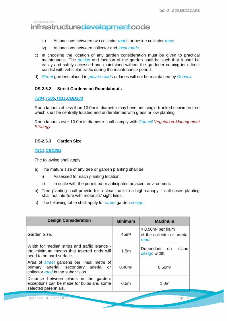
c) The following table shall apply for street garden design:
Design Consideration Minimum Maximum
Garden Size. 45m²≤ 0.50m² per lin.mof the collector or arterialroad.
Width for median strips and traffic islands -the minimum means that tapered ends willneed to be hard surface.
1.5m Dependant on islanddesign width.
Area of street gardens per lineal metre ofprimary arterial, secondary arterial orcollector road in the subdivision.
0.40m² 0.50m²
Distance between plants in the garden:exceptions can be made for bulbs and someselected perennials.
0.5m 1.0m

DS-2 STREETSCAPE
Page 6 Updated 01/07/2014
DS-2.7 Street Trees
T203,T204,T205,CBD203,CBD204,CBD205
The following shall apply:
a) Street trees shall be selected to integrate with the overall streetscape and trafficmanagement.
b) A specifically designed layer of clean, friable peat loam or sandy loam topsoil free of allperennial weeds, stones and rubbish shall be placed on the subgrade to a depth relativeto the species being used and ground conditions.
DS-2.8 Street Tree Location
Minimum planting standards for new roads shall be:
Principal RoadFunction
PrimaryLand Use
TreeSize
MinimumNumber
Location of planting /Comment
Motorway Specific design.
Expressway Specific design.
Primary Arterial Specific design.
Secondary Arterial Specific design.
Collector Residential Pb95 1 tree/lot withroad frontage
Evenly spaced alongthe Road Zoneavoiding logicallocations for the vehiclecrossings.
Commercial Pb150 1 cluster/100m of road
Clusters of no fewerthan 3 trees.
Industrial Pb150 1 cluster/100m of road
Clusters of no fewerthan 3 trees.
Local Residential Pb95 1 tree/lot withroad frontage
Evenly spaced alongthe Road Zoneavoiding logicallocations for the vehiclecrossings.
Note: Determining the layout of a cluster shall include that no detrimental effects areintroduced to any street furniture or utility.
DS-2.8.1 Street Trees on Roundabouts
Refer to DS-2.6.2 Street Gardens on Roundabouts.
DS-2 STREETSCAPE
Updated 01/07/2014 Page 7
DS-2.9 Species Selection
The following shall apply:
a) Species are to be selected with regard to overall composition, low maintenance andlongevity and shall comply with Council’s Vegetation Management Strategy, plantingpolicies and the current Plant Pest Management Strategy.
b) A list of inappropriate species has been included in DS-3 Apx B.1 Inappropriate Tree andPlant Species List. There may be species other than those listed that may be acceptableto Council. Designers are encouraged to consult with the Council regarding acceptabletree and plant species before submission of streetscape plans.
c) No plant shall be used which is identified as a National Surveillance Plant Pest or is listedby Bay of Plenty Regional Council as a plant pest.
d) The number of species used shall be consistent to ensure a unified result. The specieschoice in street gardens shall compliment the street planting, the environment and thescale of the surroundings.
e) The following matters are to be considered in species selection:
i) Environmental conditions e.g. ground moisture, wind, etc.
ii) Tolerance to amenity situation.iii) Effect of leaf debris on drainage systems.
iv) Pest and disease resistance.
v) Non-suckering habit.
vi) Longevity.
vii) Shading issues.
viii) Minimum maintenance requirements.
ix) Invasive root systems.
x) Effect of berries on paved surfaces.
f) Before planting, all species are to be quality inspected and approved by Council.
DS-2.10 Quality Control
Generally only species adapted to the site conditions shall be planted. All plant material shallbe sound, healthy, vigorous and free of any defects which may be detrimental to plantgrowth and development.
These defects are listed in CS-24 Vegetation, Planting and Gardens.
DS-2.11 Open Space Furniture and Structures
T215,T216,CBD215,CBD216,CBD340,CBD341,CBD342,CBD343,CBD350,
CBD351
The following shall apply:

DS-2 STREETSCAPE
Page 8 Updated 01/07/2014
a) Open space structures include (but are not limited to) street furniture, sculptures, walls,fences, screens, bollards, entranceways, posts, etc. and may be of materials such asconcrete, brick, stone, rock and timber. Durability and maintenance requirements shallbe considered.
b) Where street furniture (rubbish bins, seating, etc.) is proposed as part of a development itshall have a design life of no less than 15 years.
c) Structures shall not obstruct signs, sight lines at intersections and pedestrian crossings.Separation distances must be considered together with trees and other landscapingfeatures.
d) Structures shall be designed to safely withstand appropriate loadings and must notcreate a hazard.
e) Entrance features shall be located on private lots and the certificate of title shall include alegal mechanism setting out the maintenance requirements to be undertaken by the lotowner.
f) Any proposed furniture or structure shall be:
i) Robust, low maintenance, able to be safely used by the public and treated withapproved graffiti guard.
ii) Fully constructed and complete before hand over to Council.
DS-2.12 Irrigation
The following shall apply:
a) Irrigation of street gardens is generally not permitted because:
i) Plants shall be of a type that require minimum maintenance.
ii) Of the ongoing maintenance of the irrigation system.
b) Provision for irrigation during the establishment of plants is acceptable. This water useshall be metered and the cost borne by the developer.
c) Council approval is required before the installation of any semi-permanent irrigationsystem. If this is approved the Designer shall apply and pay for a metered waterconnection for irrigation purposes which shall be bonded for removal/disconnection atthe end of the landscape maintenance period.
d) Permanent irrigation shall be dealt with on a case by case basis.
DS-2.13 Incomplete Works Bond
Refer to ID-1.13 Bonds.

DS-2 STREETSCAPE
Updated 01/07/2014 Page 9
DS-2 - Appendix AAssociated Standards
DS-2 - Appendix A.1 General
The latest revision or operative version of the following standards shall be used inconjunction with the IDC:
a) Council documentation:
i) City Plan.
ii) TCC Vegetation Management Strategy.
iii) TCC Urban Design Strategy.
iv) TCC Open Space Strategy.
v) TCC Best Practice Guide for Open Space.
vi) TCC Integrated Transportation Strategy.
vii) TCC Track and Walkway – Development and Maintenance Manual.
viii) TCC Signs Policy and Manual.
ix) TCC Cycle Design Guidelines
x) TCC Plant Pest Management Strategy.
xi) TCC Best Practice Guide to Neighbourhood Reserves.
xii) TCC Planting Guide - Street Trees.
xiii) TCC Planting Guide - Street and Reserve Gardens.
xiv) TCC Development Guide.
b) New Zealand / Australian / British Standards:i) NZS 3104:2003 Specification for Concrete Production.
c) Other reference material:
i) Resource Management Act 1991.
ii) New Zealand Building Act.
iii) New Zealand Health and Safety in Employment Act 1992.
iv) New Zealand Historic Places Act.
v) New Zealand Reserves Act 1977.
vi) Modern Arboriculture by Alex Shigo.
vii) The Sunset Pruning Handbook.

DESIGN STANDARDDS-3 RESERVES
TABLE OF CONTENTS
DS-3.1 General ..............................................................................................................1
DS-3.2 Minimum Requirements ......................................................................................1
DS-3.3 Regional Council Requirements .........................................................................1
DS-3.4 Design ................................................................................................................1
DS-3.5 Further Considerations .......................................................................................4

DS-3 RESERVES
Updated 01/07/2014 Page 1
DS-3.1 General
This section sets out the requirements for the design of a reserve whether as part of asubdivision development or as part of Council’s annual work programme.
Reserves, parks and open spaces are important elements of a neighbourhood. They provideopportunities for recreation and social contact and their spaciousness can contrast with thebuilt environment of urban areas. They provide public access and recreation value toharbours, rivers and other important natural and cultural features and opportunities.
DS-3.2 Minimum Requirements
Designs shall provide for Reserves that:
a) Comply with the operative City Plan and Infrastructure Development Code (IDC).
b) Minimises, isolates or eliminates health and safety hazards during both its constructionand its uses.
c) Minimises, isolates or eliminates any adverse ecological and environmental effect.
DS-3.3 Regional Council Requirements
The Designer shall comply with all Regional Council requirements.
DS-3.4 Design
The following shall apply:
a) Unless otherwise approved by Council, the design of a Reserve shall be in accordancewith the IDC and may be supplemented by the documents listed in DS-3 Apx A –Appendix A: Associated Standards.
b) The Consent Holder may enter into an agreement with Council to allow development ofreserve land to vest. Such development work shall be in accordance with detailed plans,costings and specifications that have been approved by Council.
c) The design of a reserve shall conform with the planned future use of the reserve asdetermined by Council.
d) Earthworks may be carried out on a reserve to remove such items as tree stumps,buildings and foundations, farm tracks, cattle yards, roading aggregate etc. and toprovide maximum finished gradients.
e) A safety audit shall be carried out and all potential hazards eliminated, isolated orminimised in accordance with the requirements of the Health and Safety in EmploymentAct 1992 and its amendments.
f) Reserves shall be free from noxious & invasive weeds, tree stumps, old shelterbelts,buildings & foundations, aggregates, & any other material/s that inhibits the reservesintended use.
g) Refer to DS-2.5 Topsoil and Grassing for topsoil and grassing requirements.
DS-3 RESERVES
Page 2 Updated 01/07/2014
DS-3.4.1 Landform and Contours
The following shall apply:
a) The landform for the reserve shall be designed to be appropriate for its use and, asfar as possible, align with the adjoining landform.
b) Existing natural features shall be retained unless they do not fit with the proposeduse of the reserve as determined by the Council.
c) Refer to City Plan Reserves Performance Standards for slope details. Except wheredictated by a natural feature (e.g. an open watercourse) no batter shall be greaterthan specified to allow for mowing by tractor mounted equipment.
d) Reserve areas shall allow for adequate drainage with no ponding under normalconditions.
DS-3.4.2 Existing Trees
All existing trees that are affected by the proposed works shall be shown onInfrastructure Development Plans. This includes any intrusion within the dripline and/orroot system, access to site or other potential risks to a tree by nature of the worksoccurring.
Suitable healthy trees shall be retained where practicable. Discussion and agreementwith a Council Arborist shall take place prior to lodging Infrastructure DevelopmentPlans.
DS-3.4.3 Drainage of Reserves
The following shall apply:
a) Drainage shall be provided to and within the reserve so as to ensure that no part ofthe reserve has any excessive ponding in the event of a 5 year return period stormevent (20%AEP).
b) Internal drainage shall be connected to the main area drainage system inaccordance with the overall catchment plan for the area.
c) Internal reserve drainage may be provided by dry swales. Where a significantupstream catchment drains into and through the reserve it may be piped orchannelled through an open-drain, depending on the use of the reserve. For designmethods refer to DS-5 Stormwater.
d) Where stormwater services cross or are located within a reserve they shall beprotected by a drainage easement pursuant to the Reserves Act 1977http://www.legislation.govt.nz/act/public/1977/0066/latest/DLM444305.html.
e) Where part or all of the reserve is to be used as playing fields for active recreation, a"herring-bone" drainage system may be required to ensure adequate drainage of thefield. This system will be subject to specific design to suit local conditions andachieve the desired outcome.
Note: This section excludes drainage reserve design. Refer to DS-5 Stormwater forinformation on this.

DS-3 RESERVES
Updated 01/07/2014 Page 3
DS-3.4.4 Planting of Reserves
Reserves shall be planted in accordance with DS-3 Appendix A - Associated Standards.
DS-3.4.5 Open Space Furniture and Structures
T315, T316, T317, T330, T335, T340, T350, CBD215, CBD216, CBD340, CBD341,CBD342, CBD343, CBD350, CBD351
The following shall apply:
a) Open space structures include (but are not limited to) sculptures, walls, fences,screens, bollards, entranceways, posts, etc and may be of materials such asconcrete, brick, stone, rock and timber. Durability and maintenance requirementsshall be considered.
b) Where furniture (rubbish bins, seating, etc) are proposed as part of a reservedevelopment it shall have a design life of no less than 15 years.
c) Structures shall be located so as to not obstruct signs, sight lines at intersections andpedestrian access. Separation distances must be considered together with trees andother landscaping features.
d) Structures shall be clearly visible and safe for people to use.
e) Structures shall be designed to safely withstand appropriate loadings.
f) Entrance features shall be located within the reserve.
g) Any proposed park furniture or structures shall:
i) Be shown on the reserve development plan and submitted for approval.
ii) Be robust, low maintenance, able to be safely used by the public and treatedwith approved graffiti guard.
iii) Be fully constructed and complete before hand over to Council.
h) Should Council require the Consent Holder to undertake any reserve developmentworks associated with the construction of walkways (excluding local purposeaccessways), playgrounds, structures or park furniture, then these works will be atCouncil’s cost in accordance with an agreed level of service.
i) The Consent Holder will be responsible for obtaining all necessary approvals prior toworks beginning. Playground equipment shall comply with NZS 5828 PlaygroundEquipment and Surfacing and the New Zealand Playground Safety Manual.
DS-3.4.6 Walkways
Walkways shall be:
a) Constructed in accordance with the TCC Track and Walkway – Development andMaintenance Manual and NZS 8630 Boardwalk New Zealand Standard Outdoor andVisitor Structures.
b) Direct, as short as possible and have good sight-lines to allow casual surveillance.
c) Fenced on both sides (for all local purpose accessways).

DS-3 RESERVES
Page 4 Updated 01/07/2014
DS-3.4.6.1 Accessway Fencing
Fencing along accessways shall be one of the following:
Fence Type Maximum HeightSolid fence 1.2mPermeable fence 1.8mCombination solid and permeablefence
1.2m solidTop 0.6m permeable
Permeable fencing shall be at least 50% visually permeable.
DS-3.5 Further Considerations
The following shall also be considered as part of the design process:
a) DS-3.5.1 Landscaping
b) DS-3.5.2 Fencing
c) DS-3.5.3 Historic Places Requirements
d) DS-3.5.4 Easementse) DS-3.5.5 Incomplete Works Bond
DS-3.5.1 Landscaping
The following shall apply:
a) Generally the reserve shall be sown in grass where it is practical to be mown exceptwhere playgrounds or gardens are proposed.
b) Any land that is too steep to be safely mown or is immediately adjacent to theriparian margin shall be planted in native plants, using plant species common to thearea and appropriate to the location.
c) For further information refer to DS-2 Streetscape Design Standards and CS-23Grassing and Turfing and CS-24 Vegetation Planting and Gardens.
DS-3.5.2 Fencing
T320, T321, CBD215, CBD216, CBD220
The permanent fencing of common boundaries of any reserve including esplanade andaccessway reserves may be required as a condition of a Resource Consent orDevelopment Works Approval.
Council may specify that one or more of the following options apply:
a) A fencing covenant be registered against all titles of properties with a commonboundary to reserve land, indemnifying Council against all costs for the constructionand maintenance of fences on common boundaries.
DS-3 RESERVES
Updated 01/07/2014 Page 5
b) A fence be erected in accordance with the Standard Drawings.
c) A fence be constructed in accordance with specific site details where these occur inthe City Plan.
d) Any proposal using minimum fencing standards that does not meet the IDCrequirements will require clear justification and approval from Council for its use.
DS-3.5.3 Historic Places Requirements
All issues relating to Historic Places Act requirements shall be resolved before vesting inCouncil.
DS-3.5.4 Easements
Any assets e.g. water, network utilities etc. that have alignment through reserve landwhich is or is to be vested in Council shall require an easement in gross over that asset.The only exception to this is for stormwater assets on a drainage reserve.
DS-3.5.4.1 Land Classification
It is important that reserve land is classed correctly. It is strongly advised thatdiscussions are held with Council at an early stage of design to clarify reserve landclassification.
DS-3.5.5 Incomplete Works Bond
Refer to ID-1.13 Bonds.
DS-3 RESERVES
Page 6 Updated 01/07/2014
DS-3 - Appendix AAssociated Standards
DS-3 - Appendix A.1 General
The latest revision or operative version of the following standards shall be used inconjunction with the Infrastructure Development Code:
a) Council documentation:
i) City Plan.
ii) TCC Vegetation Management Strategy.
iii) TCC Urban Design Strategy.
iv) TCC Open Space Strategy.
v) TCC Best Practice Guide for Open Space.
vi) TCC Integrated Transportation Strategy.
vii) TCC Track and Walkway – Development and Maintenance Manual.
viii) TCC Signs Policy and Manual.
ix) TCC Plant Pest Management Strategy.
x) TCC Best Practice Guide to Neighbourhood Reserves.
xi) TCC Planting Guide - Street and Reserve Gardens.
xii) TCC Development Guide.
b) New Zealand / Australian / British Standards:
i) NZS 5828 Specifications for Playgrounds.
ii) NZS 3104:2003 Specification for Concrete Production.
c) Other reference material:
i) Resource Management Act 1991.
ii) New Zealand Building Act.
iii) New Zealand Health and Safety in Employment Act 1992.
iv) New Zealand Historic Places Act.
v) New Zealand Reserves Act 1977.
vi) Modern Arboriculture by Alex Shigo.
vii) The Sunset Pruning Handbook.
viii) New Zealand Playground Safety Manual.
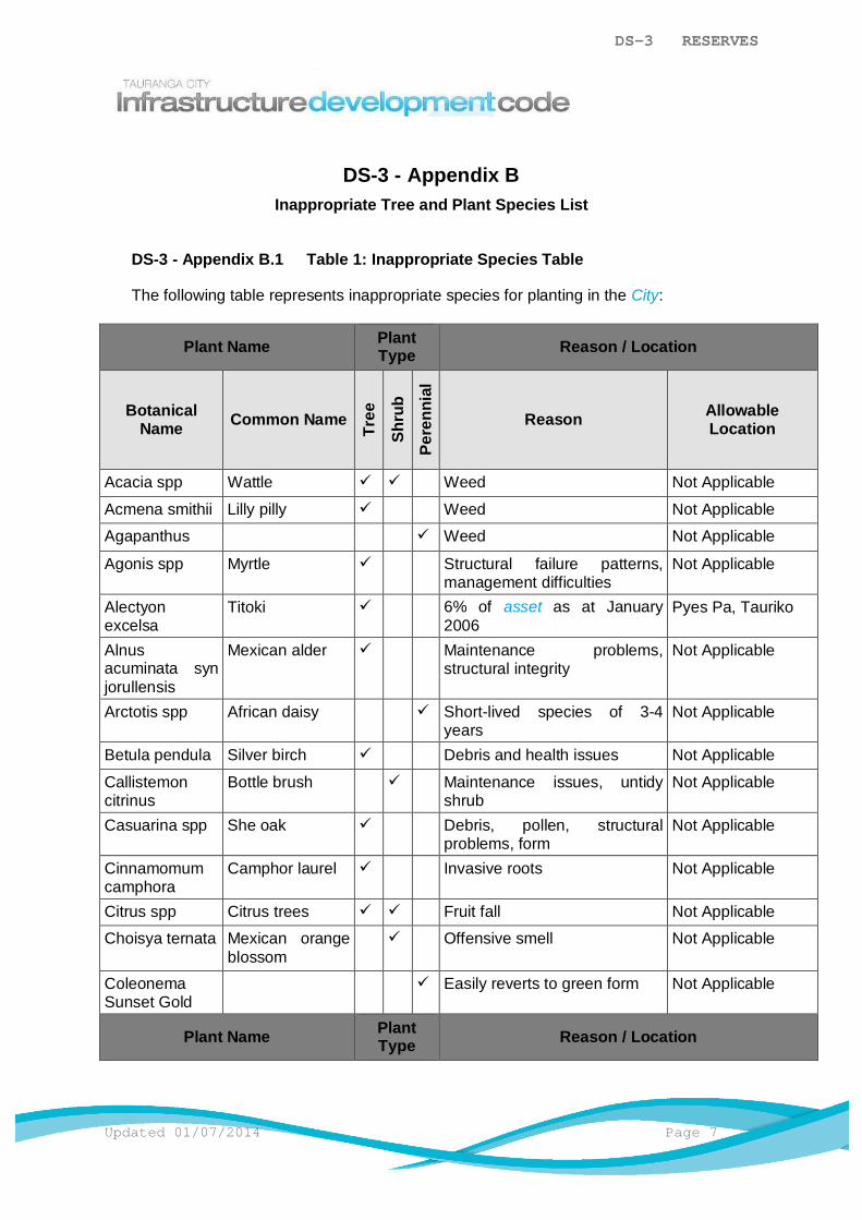
DS-3 RESERVES
Updated 01/07/2014 Page 7
DS-3 - Appendix BInappropriate Tree and Plant Species List
DS-3 - Appendix B.1 Table 1: Inappropriate Species Table
The following table represents inappropriate species for planting in the City:
Plant Name PlantType Reason / Location
BotanicalName Common Name
Tree
Shru
bPe
renn
ial
Reason AllowableLocation
Acacia spp Wattle ü ü Weed Not Applicable
Acmena smithii Lilly pilly ü Weed Not Applicable
Agapanthus ü Weed Not Applicable
Agonis spp Myrtle ü Structural failure patterns,management difficulties
Not Applicable
Alectyonexcelsa
Titoki ü 6% of asset as at January2006
Pyes Pa, Tauriko
Alnusacuminata synjorullensis
Mexican alder ü Maintenance problems,structural integrity
Not Applicable
Arctotis spp African daisy ü Short-lived species of 3-4years
Not Applicable
Betula pendula Silver birch ü Debris and health issues Not Applicable
Callistemoncitrinus
Bottle brush ü Maintenance issues, untidyshrub
Not Applicable
Casuarina spp She oak ü Debris, pollen, structuralproblems, form
Not Applicable
Cinnamomumcamphora
Camphor laurel ü Invasive roots Not Applicable
Citrus spp Citrus trees ü ü Fruit fall Not Applicable
Choisya ternata Mexican orangeblossom
ü Offensive smell Not Applicable
ColeonemaSunset Gold
ü Easily reverts to green form Not Applicable
Plant Name PlantType Reason / Location
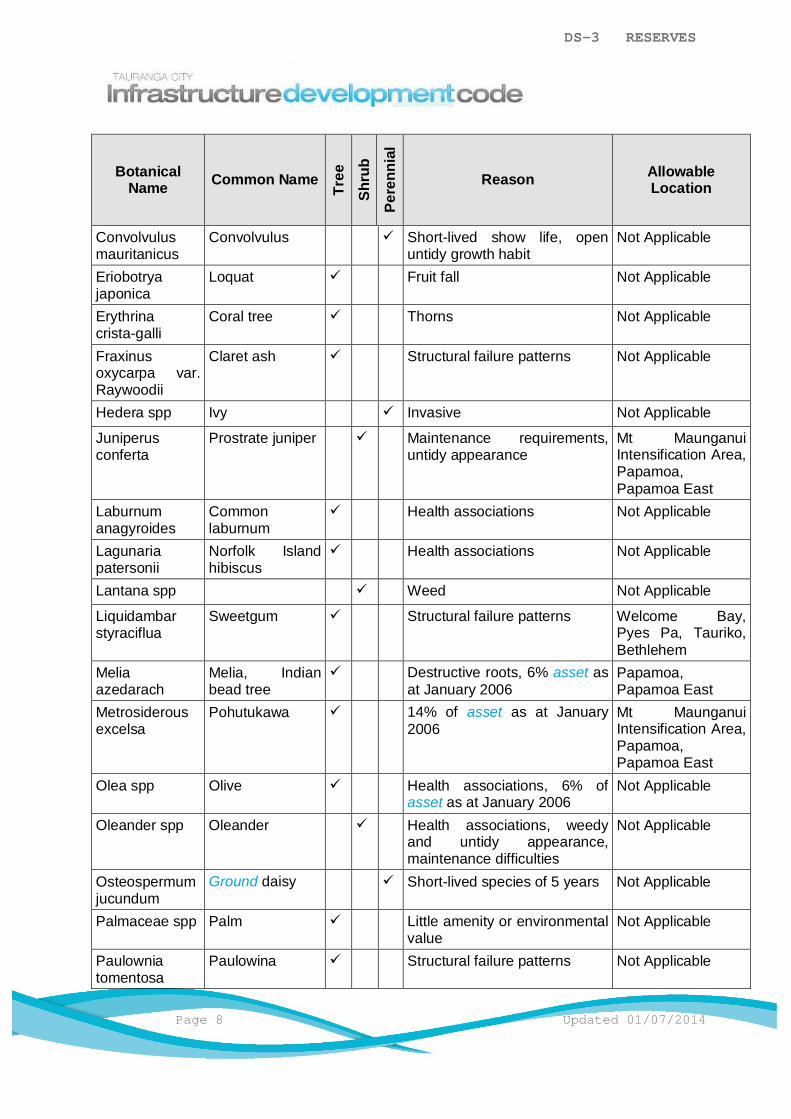
DS-3 RESERVES
Page 8 Updated 01/07/2014
BotanicalName Common Name
Tree
Shru
b
Pere
nnia
l
Reason AllowableLocation
Convolvulusmauritanicus
Convolvulus ü Short-lived show life, openuntidy growth habit
Not Applicable
Eriobotryajaponica
Loquat ü Fruit fall Not Applicable
Erythrinacrista-galli
Coral tree ü Thorns Not Applicable
Fraxinusoxycarpa var.Raywoodii
Claret ash ü Structural failure patterns Not Applicable
Hedera spp Ivy ü Invasive Not Applicable
Juniperusconferta
Prostrate juniper ü Maintenance requirements,untidy appearance
Mt MaunganuiIntensification Area,Papamoa,Papamoa East
Laburnumanagyroides
Commonlaburnum
ü Health associations Not Applicable
Lagunariapatersonii
Norfolk Islandhibiscus
ü Health associations Not Applicable
Lantana spp ü Weed Not Applicable
Liquidambarstyraciflua
Sweetgum ü Structural failure patterns Welcome Bay,Pyes Pa, Tauriko,Bethlehem
Meliaazedarach
Melia, Indianbead tree
ü Destructive roots, 6% asset asat January 2006
Papamoa,Papamoa East
Metrosiderousexcelsa
Pohutukawa ü 14% of asset as at January2006
Mt MaunganuiIntensification Area,Papamoa,Papamoa East
Olea spp Olive ü Health associations, 6% ofasset as at January 2006
Not Applicable
Oleander spp Oleander ü Health associations, weedyand untidy appearance,maintenance difficulties
Not Applicable
Osteospermumjucundum
Ground daisy ü Short-lived species of 5 years Not Applicable
Palmaceae spp Palm ü Little amenity or environmentalvalue
Not Applicable
Paulowniatomentosa
Paulowina ü Structural failure patterns Not Applicable
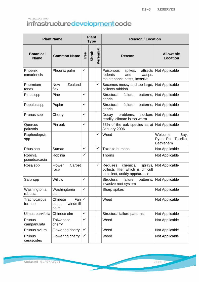
DS-3 RESERVES
Updated 01/07/2014 Page 9
Plant Name PlantType Reason / Location
BotanicalName Common Name
Tree
Shru
bPe
renn
ial
Reason AllowableLocation
Phoenixcanariensis
Phoenix palm ü Poisonous spikes, attractsrodents and wasps,maintenance costs, invasive
Not Applicable
Phormiumtenax
New Zealandflax
ü Becomes messy and too large,collects rubbish
Not Applicable
Pinus spp Pine ü Structural failure patterns,debris
Not Applicable
Populus spp Poplar ü Structural failure patterns,debris
Not Applicable
Prunus spp Cherry ü Decay problems, suckersreadily, climate is too warm
Not Applicable
Quercuspalustris
Pin oak ü 53% of the oak species as atJanuary 2006
Not Applicable
Rapheolepsisspp
ü Weed Welcome Bay,Pyes Pa, Tauriko,Bethlehem
Rhus spp Sumac ü ü Toxic to humans Not Applicable
Robiniapseudoacacia
Robinia ü Thorns Not Applicable
Rosa spp Flower Carpetrose
ü Requires chemical sprays,collects litter which is difficultto collect, untidy appearance
Not Applicable
Salix spp Willow ü Structural failure patterns,invasive root system
Not Applicable
Washingtoniarobusta
Washingtoniapalm
ü Sharp spikes Not Applicable
Trachycarpusfortunei
Chinese Fanpalm, windmillpalm
ü Weed Not Applicable
Ulmus parvifolia Chinese elm ü Structural failure patterns Not Applicable
Prunuscampanulata
Taiwanesecherry
ü Weed Not Applicable
Prunus avium Flowering cherry ü Weed Not Applicable
Prunuscerasoides
Flowering cherry ü Weed Not Applicable
DESIGN STANDARDDS-4 TRANSPORTATION NETWORK
TABLE OF CONTENTS
DS-4.1 General ..............................................................................................................1
DS-4.2 Minimum Requirements ......................................................................................1
DS-4.3 Regional Council Requirements .........................................................................1
DS-4.4 Design ................................................................................................................1
DS-4.5 Conveyance .......................................................................................................3
DS-4.6 Marking and Signs ............................................................................................15
DS-4.7 Connection .......................................................................................................15
DS-4.8 Berm Features..................................................................................................18
DS-4.9 Further Considerations .....................................................................................22
DS-4 TRANSPORTATION NETWORK
Updated 01/07/2014 Page 1
DS-4.1 General
This section looks at the way in which a transportation network is laid out and the elementsthat contribute to them. Transportation networks are not easily modified, therefore carefulconsideration shall be given to the street layout, block size, street orientation, level ofconnectivity and width of the Road Zone or connection. It is essential that the network is wellconnected and designed to ensure safety, comfort, efficiency, reduced energy use andamenity for a range of users.
Other considerations to be made when designing transportation networks include:
a) Underground and above-ground network utilities.
b) Streetscape elements.
c) Street furniture.
d) Low impact design methods.
DS-4.2 Minimum Requirements
Designs shall provide a transportation network that:
a) Complies with the operative City Plan and Infrastructure Development Code (IDC).
b) Is designed to acceptable engineering methods and standards.c) Incorporates the needs of all Road Zone users including pedestrians, cyclists, mobility
vehicles etc.
d) Minimises, isolates or eliminates health and safety hazards during both construction andits use.
e) Minimises, isolates or eliminates any adverse ecological and environmental effects.
DS-4.3 Regional Council Requirements
Installation of bridges or culverts on natural watercourses are generally subject to a Bay ofPlenty Regional Council Resource Consent or in some cases the works may be covered bya Permitted Activity status. Design and construction of these shall comply with allrequirements of the Resource Consent or Permitted Activity criteria.
The advice of the Bay of Plenty Regional Council shall be sought at an early stage in thedesign process.
DS-4.4 Design
T400
The following shall apply:
DS-4 TRANSPORTATION NETWORK
Page 2 Updated 01/07/2014
a) Unless otherwise approved by Council, the design of the transportation network shall bein accordance with the IDC but may be supplemented by the documents noted in DS-4Apx A.1 General. Consideration shall be given to pedestrian/cycle use in the design ofany road.
b) A transportation network computer modelling system approved by Council may also beused.
c) Low impact design tools and techniques for transportation design, where appropriate, willbe considered by Council. Such methods, in addition to those mentioned below mayinclude features and techniques such as reduction in impermeable surfaces, permeablepaving and filter strips. Concept approval is required from Council before undertakinglow impact design.
d) In all cases the designer shall confirm with Council the classification of roads in thevicinity of the proposed infrastructure development and ensure that the roading designconforms to the correct road hierarchy. The road hierarchy within Tauranga City isshown on the hierarchy map in the Standard Drawings.
e) All arterial and collector roads shall be designed to cater for public transportrequirements.
f) A safety audit report may be required. Refer to DS-4 Apx D Safety Audits and Table1-Design Requirements for Various Road Classifications for all safety auditingrequirements.Detailed design shall be required at the time of Infrastructure Development WorksApproval. Where no Infrastructure Development Works Approval is required, Councilapproval shall be obtained at a time required by Council and before the construction ofthe system.
DS-4.4.1 Urban Roads
Where not otherwise covered by the IDC all urban roads shall be designed inaccordance with the widths and gradients detailed on DS-4.5.1.1Table 1: DesignRequirements for Various Road Classifications and the Austroads publicationsGuidelines to Traffic Engineering Practice and Guidelines for Urban Road DesignAPGE9/2.
Attention is drawn to the requirements of New Zealand Standard specifications,standards and guidelines to be met as appropriate to good practice for the design ofurban roads.
In the case of urban roads intersecting or joining State Highways, early consultation shallbe made with the New Zealand Transport Agency with regard to appropriate standards.
DS-4.4.2 Rural Roads
Where not otherwise covered by the IDC all rural roads shall also be designed inaccordance with Austroads Rural Road Guide The Geometric Design of Rural Roads.
DS-4 TRANSPORTATION NETWORK
Updated 01/07/2014 Page 3
DS-4.5 Conveyance
DS-4.5.1 Widths, Lengths and Grades
T400, T405
The following shall apply:
a) Only Road Zones with a minimum width of 12m shall be accepted for vesting inCouncil.
b) Road Zones with widths narrower than 12m will be private ways. Maintenance shallbe the responsibility of the owners of the lots that are served by the private way.
DS-4.5.1.1 Urban Roads
DS-4.5.1.1 Table 1: Design Requirements for Various Road Classifications applies tourban roads and private ways.
The following shall also apply:
a) Carriageway widths shall be measured between kerb faces.b) The minimum Road Zone and carriageway widths shown in the table make no
allowance for additional intersection requirements, batters, embankments orroad widening for horizontal curves. Specific design is required for everyintersection before Infrastructure Development Works Approval. This shalldetermine final boundary locations in order to provide acceptable sightdistances.
c) Carriageway width may be determined taking account of:
i) Public transportation requirements.
ii) The likelihood of opposing traffic.
iii) The likelihood of continuous parking on both sides of the road.
iv) The likelihood of vehicles turning into driveways.
v) Carriageway space for cyclists as covered in Austroads Guide to TrafficManagement, Austroads Guide to Road Design and Austroads Guide toRoad Safety.
d) Where the stated requirements for private ways are not met, the applicant shallstate in detail the arrangements to be made for:
i) Access for fire appliances.
ii) Refuse collection.
iii) Directions for emergency services.
iv) Postal delivery.v) Stormwater runoff control.
e) Cycleway design shall, as a minimum, comply with the New ZealandSupplement to the Austroads Guide to Traffic Engineering Practice, Part 14:Bicycles.

DS-4 TRANSPORTATION NETWORK
Page 4 Updated 01/07/2014
f) The minimum gradient for all roads with kerb and channel shall be 0.50%(1:200) on both sides of the road other than on transitions to super elevations.
g) The gradient within 30m of an intersection on urban streets shall not exceedplus or minus 10% longitudinally and shall preferably be less than +/- 3%crossfall.
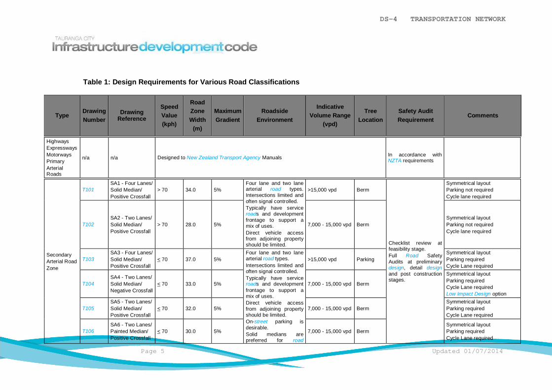
DS-4 TRANSPORTATION NETWORK
Page 5 Updated 01/07/2014
Table 1: Design Requirements for Various Road Classifications
TypeDrawingNumber
DrawingReference
SpeedValue(kph)
RoadZoneWidth
(m)
MaximumGradient
RoadsideEnvironment
IndicativeVolume Range
(vpd)
TreeLocation
Safety AuditRequirement
Comments
HighwaysExpresswaysMotorwaysPrimaryArterialRoads
n/a n/a Designed to New Zealand Transport Agency Manuals In accordance withNZTA requirements
SecondaryArterial RoadZone
T101SA1 - Four Lanes/Solid Median/Positive Crossfall
> 70 34.0 5%Four lane and two lanearterial road types.Intersections limited andoften signal controlled.Typically have serviceroads and developmentfrontage to support amix of uses.Direct vehicle accessfrom adjoining propertyshould be limited.
>15,000 vpd Berm
Checklist review atfeasibility stage.Full Road SafetyAudits at preliminarydesign, detail designand post constructionstages.
Symmetrical layoutParking not requiredCycle lane required
T102SA2 - Two Lanes/Solid Median/Positive Crossfall
> 70 28.0 5% 7,000 - 15,000 vpd BermSymmetrical layoutParking not requiredCycle lane required
T103SA3 - Four Lanes/Solid Median/Positive Crossfall
< 70 37.0 5%Four lane and two lanearterial road types.Intersections limited andoften signal controlled.Typically have serviceroads and developmentfrontage to support amix of uses.Direct vehicle accessfrom adjoining propertyshould be limited.On-street parking isdesirable.Solid medians arepreferred for road
>15,000 vpd ParkingSymmetrical layoutParking requiredCycle Lane required
T104SA4 - Two Lanes/Solid Median/Negative Crossfall
< 70 33.0 5% 7,000 - 15,000 vpd Berm
Symmetrical layoutParking requiredCycle Lane requiredLow Impact Design option
T105SA5 - Two Lanes/Solid Median/Positive Crossfall
< 70 32.0 5% 7,000 - 15,000 vpd BermSymmetrical layoutParking requiredCycle Lane required
T106SA6 - Two Lanes/Painted Median/Positive Crossfall
< 70 30.0 5% 7,000 - 15,000 vpd BermSymmetrical layoutParking requiredCycle Lane required

DS-4 TRANSPORTATION NETWORK
Page 6 Updated 01/07/2014
sections with highdemand for crosspedestrian movements.
CollectorRoadZone
T107CR1 - Four LanesMedian/Positive Crossfall
50 31.0 8.33%
Typically have serviceroads and developmentfrontage to support amix of uses.Direct vehicle accessfrom adjoining propertyshould be limited.On-street parking couldbe considered insideactivity centres and thiswould increase the RoadZone by 4.5m.
>15,000 vpd Berm
Checklist review atpreliminary designstage.Full Road SafetyAudits at detail designand post constructionstages.
Symmetrical layoutParking may be required.Cycle Lane required
T108CR2 - Two Lanes/Solid Median/Negative Crossfall
50 30.0 8.33% Mostly residentialfrontage that linksneighbourhoods withtown centres. A twolane undivided road forhigher volumecollectors.Typically canaccommodate busesand separate on-streetcycle lanes. These areoften ‘special roads’ andtheir design needs tohave particular regard tocontext, function andadjacent land use.
7,000 – 15,000vpd Berm
Symmetrical layoutParking requiredCycle Lane requiredLow impact design option
T109CR3 - Two Lanes/Solid Median/Positive Crossfall
50 29.0 8.33% 7,000 – 15,000vpd Berm
Symmetrical layoutParking requiredCycle Lane required
T110CR4 - Two Lanes/Painted Median/Positive Crossfall
50 25.5 8.33% 5,000 – 12,000vpd Parking
Symmetrical layoutParking requiredCycle Lane requiredPainted median may bereduced to 2.0m and RoadReserve reduced to 25.0m ifthere is a low proportion ofheavy vehicles
T111CR5 - Two Lanes/No Median/Positive Crossfall
50 23.0 8.33% 3,000 – 5,500 vpd ParkingSymmetrical layoutParking requiredCycle Lane required
IndustrialRoad Zone
T112CI1 - Two Lanes/No Median/Positive Crossfall
50 23.0 5%
For use in industrialzones. Highpercentage of trucksexpected.
<5,000 vpd Berm
Checklist review atpreliminary designstage.Full Road SafetyAudits at detail designand post constructionstages.
Symmetrical layoutParking requiredCycle Lane not required
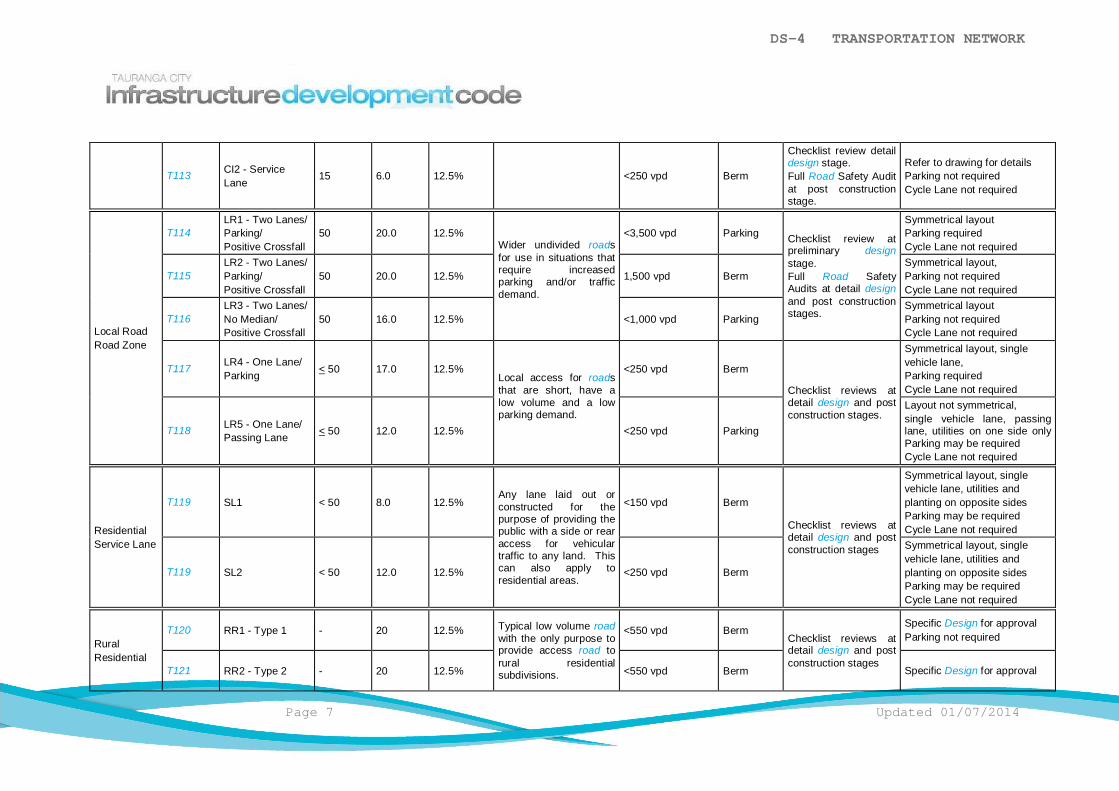
DS-4 TRANSPORTATION NETWORK
Page 7 Updated 01/07/2014
T113 CI2 - ServiceLane
15 6.0 12.5% <250 vpd Berm
Checklist review detaildesign stage.Full Road Safety Auditat post constructionstage.
Refer to drawing for detailsParking not requiredCycle Lane not required
Local RoadRoad Zone
T114LR1 - Two Lanes/Parking/Positive Crossfall
50 20.0 12.5%Wider undivided roadsfor use in situations thatrequire increasedparking and/or trafficdemand.
<3,500 vpd Parking Checklist review atpreliminary designstage.Full Road SafetyAudits at detail designand post constructionstages.
Symmetrical layoutParking requiredCycle Lane not required
T115LR2 - Two Lanes/Parking/Positive Crossfall
50 20.0 12.5% 1,500 vpd BermSymmetrical layout,Parking not requiredCycle Lane not required
T116LR3 - Two Lanes/No Median/Positive Crossfall
50 16.0 12.5% <1,000 vpd ParkingSymmetrical layoutParking not requiredCycle Lane not required
T117 LR4 - One Lane/Parking < 50 17.0 12.5%
Local access for roadsthat are short, have alow volume and a lowparking demand.
<250 vpd Berm
Checklist reviews atdetail design and postconstruction stages.
Symmetrical layout, singlevehicle lane,Parking requiredCycle Lane not required
T118 LR5 - One Lane/Passing Lane < 50 12.0 12.5% <250 vpd Parking
Layout not symmetrical,single vehicle lane, passinglane, utilities on one side onlyParking may be requiredCycle Lane not required
ResidentialService Lane
T119 SL1 < 50 8.0 12.5%Any lane laid out orconstructed for thepurpose of providing thepublic with a side or rearaccess for vehiculartraffic to any land. Thiscan also apply toresidential areas.
<150 vpd Berm
Checklist reviews atdetail design and postconstruction stages
Symmetrical layout, singlevehicle lane, utilities andplanting on opposite sidesParking may be requiredCycle Lane not required
T119 SL2 < 50 12.0 12.5% <250 vpd Berm
Symmetrical layout, singlevehicle lane, utilities andplanting on opposite sidesParking may be requiredCycle Lane not required
RuralResidential
T120 RR1 - Type 1 - 20 12.5% Typical low volume roadwith the only purpose toprovide access road torural residentialsubdivisions.
<550 vpd BermChecklist reviews atdetail design and postconstruction stages
Specific Design for approvalParking not required
T121 RR2 - Type 2 - 20 12.5% <550 vpd Berm Specific Design for approval
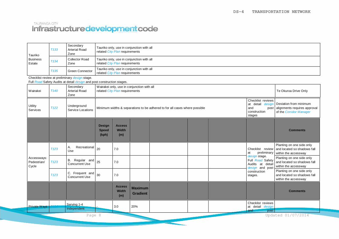
DS-4 TRANSPORTATION NETWORK
Page 8 Updated 01/07/2014
TaurikoBusinessEstate
T133SecondaryArterial RoadZone
Tauriko only, use in conjunction with allrelated City Plan requirements
T134 Collector RoadZone
Tauriko only, use in conjunction with allrelated City Plan requirements
T135 Green Connector Tauriko only, use in conjunction with allrelated City Plan requirements
Checklist review at preliminary design stage.Full Road Safety Audits at detail design and post construction stages.
Wairakei T140SecondaryArterial RoadZone
Wairakei only, use in conjunction with allrelated City Plan requirements Te Okuroa Drive Only
UtilityServices
T122 UndergroundService Locations Minimum widths & separations to be adhered to for all cases where possible
Checklist reviewsat detail designand postconstructionstages
Deviation from minimumalignments requires approvalof the Corridor Manager
DesignSpeed(kph)
AccessWidth
(m)Comments
Accessways:Pedestrian/Cycle
T123 A. RecreationalUse 20 7.0 Checklist review
at preliminarydesign stage.Full Road SafetyAudits at detaildesign and postconstructionstages.
Planting on one side onlyand located so shadows fallwithin the accessway
T123 B. Regular andConcurrent Use 25 7.0
Planting on one side onlyand located so shadows fallwithin the accessway
T123 C. Frequent andConcurrent Use 30 7.0
Planting on one side onlyand located so shadows fallwithin the accessway
AccessWidth
(m)
MaximumGradient
Comments
Private Ways T124 Serving 1-4Independent - 3.0 20%
Checklist reviewsat detail designand post
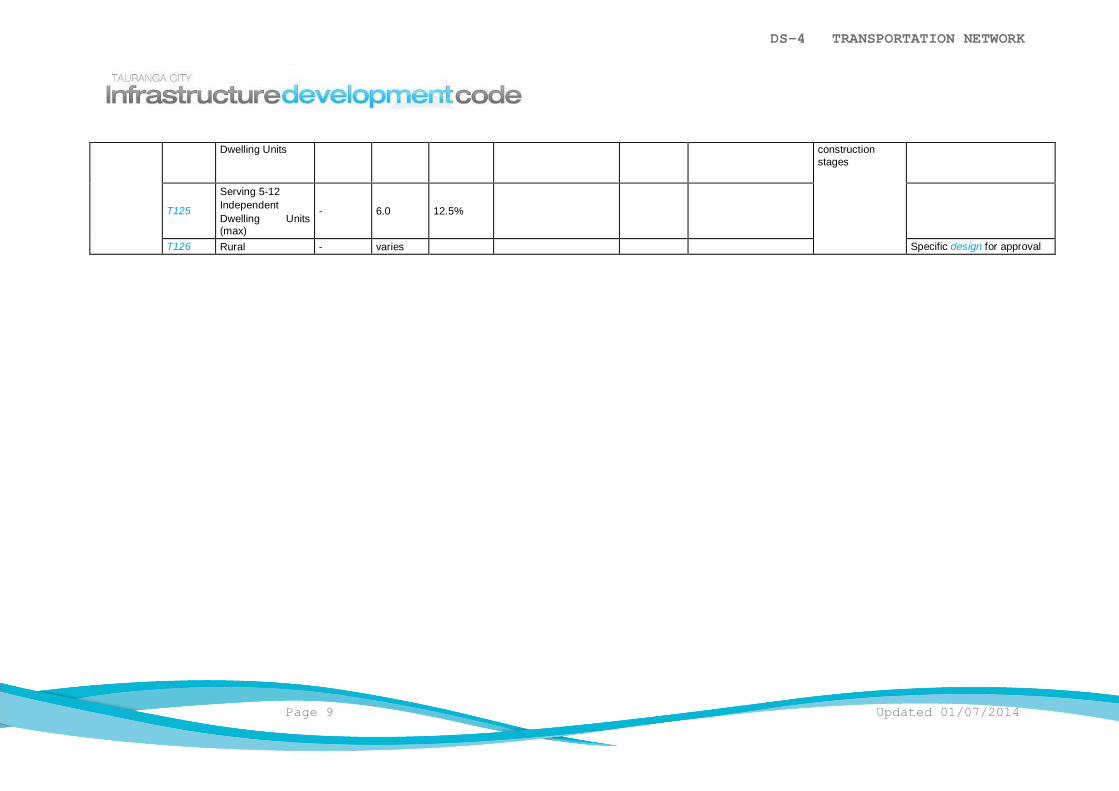
DS-4 TRANSPORTATION NETWORK
Page 9 Updated 01/07/2014
Dwelling Units constructionstages
T125
Serving 5-12IndependentDwelling Units(max)
- 6.0 12.5%
T126 Rural - varies Specific design for approval

DS-4 TRANSPORTATION NETWORK
Updated 01/07/2014 Page 1
DS-4.5.1.2 Rural Roads
The following shall apply:
a) The minimum required carriageway and Road Zone width for rural roads isdetermined by calculating the average daily traffic volume (ADT) and thenreferring to DS-4.5.1.2 Table 2: Requirements for Carriageway and Road ZoneWidths for Different Classifications of Rural Roads. The calculation of ADT takesaccount of the terrain and the predicted percentage of heavy commercialvehicles by applying factors to a formula as below:
i) Traffic volume – shall be assessed on the following basis:
Lots of 4ha or greater in area
Lots less than 4ha in area
15 vehicle movements/day/lot
10 vehicle movements/day/lot
ii) Factors for percentage Heavy Commercial Vehicles (HCVs):
Cars
HCVs
90%
10%
iii) Factors for types of terrain:
Cars Level 1.0 Rolling 1.0 Mountainous 1.0
Trucks Level 2.2 Rolling 5.0 Mountainous 10.0
Buses Level 2.0 Rolling 3.4 Mountainous 6.0
iv) Calculation
Multiply the traffic generation from each lot by the percentage composition forcars and HCVs and then multiply by the factor for the type of terrain.
Example: Lot area = 20ha
Terrain is Rolling - Total vpd = 15
ADT Calculation:
Cars
HCVs
Total ADT
= 15 x 90% x 1.0 = 13.5
= 15 x 10% x 5.0 = 7.5
= 21.0
b) DS-4.5.1.2 Table 2: Requirements for Carriageway and Road Zone Widths forDifferent Classifications of Rural Roads sets out the requirements forcarriageway and Road Zone widths for different classifications of "Rural" roads.
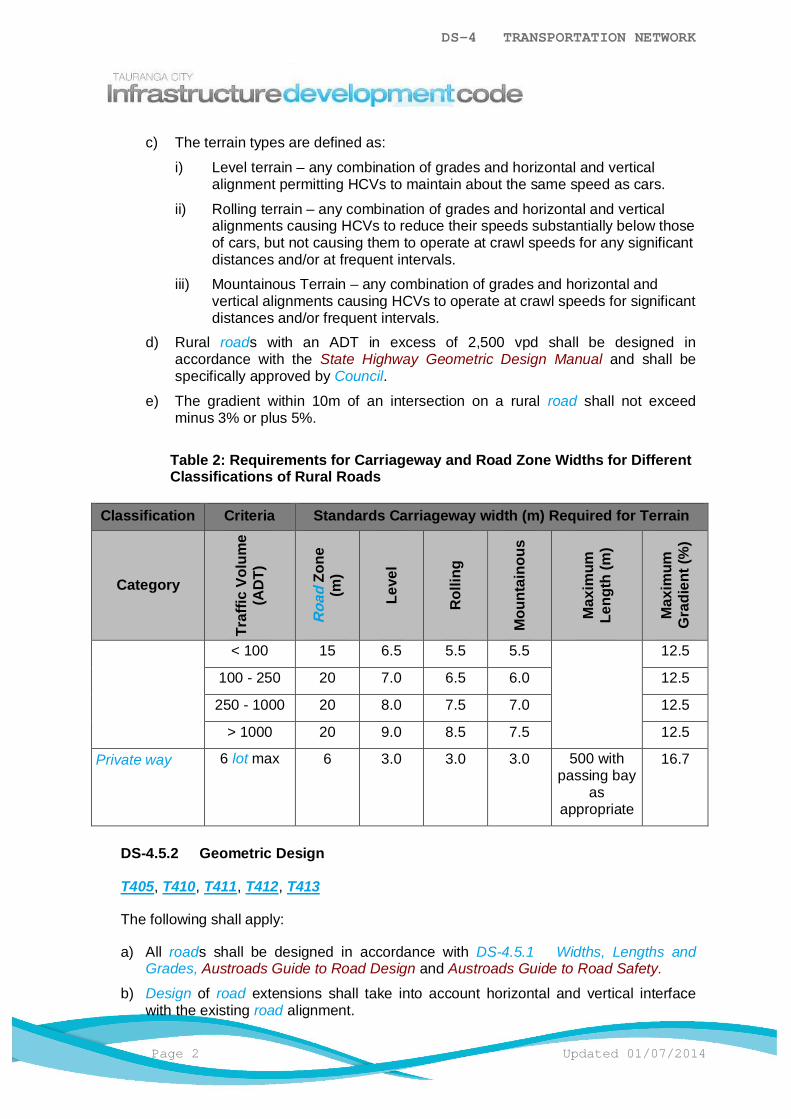
DS-4 TRANSPORTATION NETWORK
Page 2 Updated 01/07/2014
c) The terrain types are defined as:
i) Level terrain – any combination of grades and horizontal and verticalalignment permitting HCVs to maintain about the same speed as cars.
ii) Rolling terrain – any combination of grades and horizontal and verticalalignments causing HCVs to reduce their speeds substantially below thoseof cars, but not causing them to operate at crawl speeds for any significantdistances and/or at frequent intervals.
iii) Mountainous Terrain – any combination of grades and horizontal andvertical alignments causing HCVs to operate at crawl speeds for significantdistances and/or frequent intervals.
d) Rural roads with an ADT in excess of 2,500 vpd shall be designed inaccordance with the State Highway Geometric Design Manual and shall bespecifically approved by Council.
e) The gradient within 10m of an intersection on a rural road shall not exceedminus 3% or plus 5%.
Table 2: Requirements for Carriageway and Road Zone Widths for DifferentClassifications of Rural Roads
Classification Criteria Standards Carriageway width (m) Required for Terrain
Category
Traf
ficVo
lum
e(A
DT)
Road
Zone
(m)
Leve
l
Rol
ling
Mou
ntai
nous
Max
imum
Leng
th(m
)
Max
imum
Gra
dien
t(%
)
< 100 15 6.5 5.5 5.5 12.5
100 - 250 20 7.0 6.5 6.0 12.5
250 - 1000 20 8.0 7.5 7.0 12.5
> 1000 20 9.0 8.5 7.5 12.5
Private way 6 lot max 6 3.0 3.0 3.0 500 withpassing bay
asappropriate
16.7
DS-4.5.2 Geometric Design
T405, T410, T411, T412, T413
The following shall apply:
a) All roads shall be designed in accordance with DS-4.5.1 Widths, Lengths andGrades, Austroads Guide to Road Design and Austroads Guide to Road Safety.
b) Design of road extensions shall take into account horizontal and vertical interfacewith the existing road alignment.
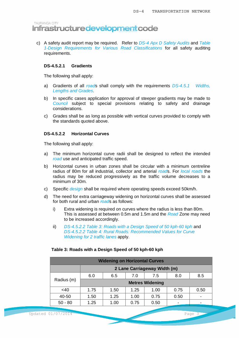
DS-4 TRANSPORTATION NETWORK
Updated 01/07/2014 Page 3
c) A safety audit report may be required. Refer to DS-4 Apx D Safety Audits and Table1-Design Requirements for Various Road Classifications for all safety auditingrequirements.
DS-4.5.2.1 Gradients
The following shall apply:
a) Gradients of all roads shall comply with the requirements DS-4.5.1 Widths,Lengths and Grades.
b) In specific cases application for approval of steeper gradients may be made toCouncil subject to special provisions relating to safety and drainageconsiderations.
c) Grades shall be as long as possible with vertical curves provided to comply withthe standards quoted above.
DS-4.5.2.2 Horizontal Curves
The following shall apply:
a) The minimum horizontal curve radii shall be designed to reflect the intendedroad use and anticipated traffic speed.
b) Horizontal curves in urban zones shall be circular with a minimum centrelineradius of 80m for all industrial, collector and arterial roads. For local roads theradius may be reduced progressively as the traffic volume decreases to aminimum of 30m.
c) Specific design shall be required where operating speeds exceed 50km/h.
d) The need for extra carriageway widening on horizontal curves shall be assessedfor both rural and urban roads as follows:
i) Extra widening is required on curves where the radius is less than 80m.This is assessed at between 0.5m and 1.5m and the Road Zone may needto be increased accordingly.
ii) DS-4.5.2.2 Table 3: Roads with a Design Speed of 50 kph-60 kph andDS-4.5.2.2 Table 4: Rural Roads: Recommended Values for CurveWidening for 2 traffic lanes apply.
Table 3: Roads with a Design Speed of 50 kph-60 kph
Widening on Horizontal Curves2 Lane Carriageway Width (m)
Radius (m)6.0 6.5 7.0 7.5 8.0 8.5
Metres Widening<40 1.75 1.50 1.25 1.00 0.75 0.50
40-50 1.50 1.25 1.00 0.75 0.50 -50 - 80 1.25 1.00 0.75 0.50 - -
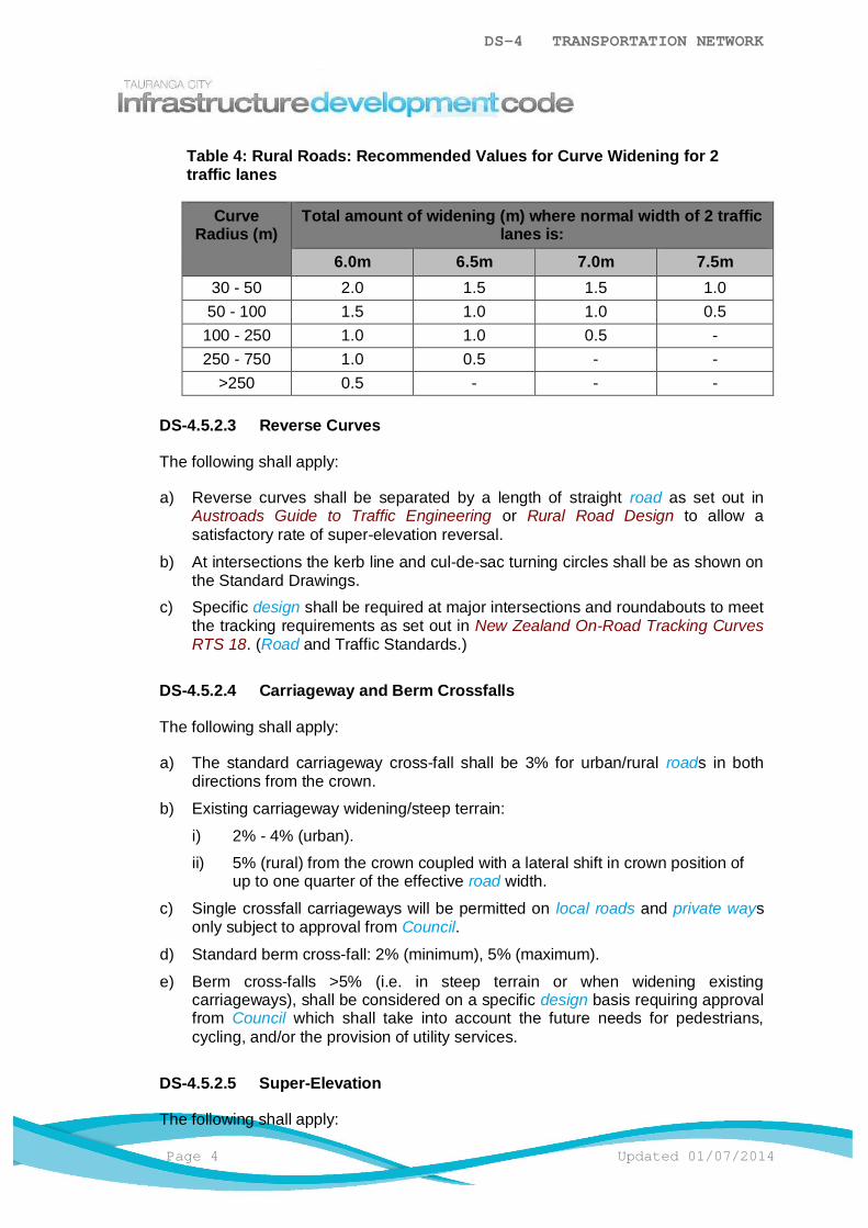
DS-4 TRANSPORTATION NETWORK
Page 4 Updated 01/07/2014
Table 4: Rural Roads: Recommended Values for Curve Widening for 2traffic lanes
CurveRadius (m)
Total amount of widening (m) where normal width of 2 trafficlanes is:
6.0m 6.5m 7.0m 7.5m30 - 50 2.0 1.5 1.5 1.050 - 100 1.5 1.0 1.0 0.5
100 - 250 1.0 1.0 0.5 -250 - 750 1.0 0.5 - -
>250 0.5 - - -
DS-4.5.2.3 Reverse Curves
The following shall apply:
a) Reverse curves shall be separated by a length of straight road as set out inAustroads Guide to Traffic Engineering or Rural Road Design to allow asatisfactory rate of super-elevation reversal.
b) At intersections the kerb line and cul-de-sac turning circles shall be as shown onthe Standard Drawings.
c) Specific design shall be required at major intersections and roundabouts to meetthe tracking requirements as set out in New Zealand On-Road Tracking CurvesRTS 18. (Road and Traffic Standards.)
DS-4.5.2.4 Carriageway and Berm Crossfalls
The following shall apply:
a) The standard carriageway cross-fall shall be 3% for urban/rural roads in bothdirections from the crown.
b) Existing carriageway widening/steep terrain:
i) 2% - 4% (urban).
ii) 5% (rural) from the crown coupled with a lateral shift in crown position ofup to one quarter of the effective road width.
c) Single crossfall carriageways will be permitted on local roads and private waysonly subject to approval from Council.
d) Standard berm cross-fall: 2% (minimum), 5% (maximum).
e) Berm cross-falls >5% (i.e. in steep terrain or when widening existingcarriageways), shall be considered on a specific design basis requiring approvalfrom Council which shall take into account the future needs for pedestrians,cycling, and/or the provision of utility services.
DS-4.5.2.5 Super-Elevation
The following shall apply:

DS-4 TRANSPORTATION NETWORK
Updated 01/07/2014 Page 5
a) For urban roads super-elevation shall be applied to curves on all roads wherethe speed environment exceeds 70kph and to approved arterial roads inaccordance with Austroads Urban Road Design, Guide to the Geometric Designof Major Urban Roads.
b) For rural roads refer to the Austroads Rural Road Design Guide to theGeometric Design of Rural Roads.
DS-4.5.2.6 Cut / Fill Batters
The following shall apply:
a) Urban Roads
i) Cut and fill batters for roads shall be constructed within the Road Zonewith a maximum grade of 20% (1:5) starting at the road boundary. Thereshall be provision for forming a vehicular entrance into each lot at agradient not steeper than 20% from the back of the footpath and allowancemade for the retention of stormwater runoff in the road channel.
ii) Where circumstances dictate a steeper grade is necessary, a geotechnicalassessment of the slope shall be provided together with specific accessdesign.
iii) Road batters for cuttings and embankments shall normally be constructedoutside the Road Zone and any batters encroaching the street boundarymay only be allowed only at the discretion of Council. Provided suchdispensation is permitted, the face of the batter shall be protected asdirected by the Council.
iv) Any retaining wall designed to support the road or footpath shall beconstructed within the Road Zone and may require a building consent.
v) Where in the opinion of Council the stability of any planned embankment isin doubt, the Consent Holder may be required to provide a stabilityanalysis of the slope under saturated conditions.
b) Rural Roads
i) Rural batters for cuttings and embankments shall usually be constructedinside the Road Zone.
ii) Batters less than 750mm high shall be cut at 1:4 and shall be topsoiledand grassed.
iii) Batters 750mm high and above shall be cut at 2H:1V and shall beprotected from face erosion by hydro-seeding or similar.
iv) Batters 4.5m high and above shall be assessed by a Geo-Professional.In undertaking this check the Geo-Professional shall take into account:
a) The type of soils present in the cutting.
b) The degree of possible erosion and its effect on long term stability andthe safety of road users and adjacent property owners.
c) A stability check based on effective stress analyses and appropriategroundwater conditions.
DS-4 TRANSPORTATION NETWORK
Page 6 Updated 01/07/2014
v) Stormwater disposal from cut or fill batter benches shall be by pipe, flumeor other approved structure.
DS-4.5.2.7 Intersection Design
T410, T411, T412, T413, T414, T415, T416
The following shall apply:
a) Intersections involving Collector, Arterial Roads, Expressways or Motorwaysrequire specific design.
b) All intersections shall be designed according with Austroads Guideline for TrafficEngineering Practice Part 5 – Intersections at Grade.
c) The separation between any two roads intersecting a collector road or higherclassification shall be a minimum distance of 150m centreline to centreline. Twominor access roads intersecting a local road shall be offset at least 60mcentreline to centreline.
d) All urban intersections shall have splitter islands to maintain lane widths.
e) All rural intersections with an 8.0m carriageway and above shall include kerband channel.
f) All rural intersections with an existing or calculated ADT greater than 250vpdrequire splitter islands.
g) Rural Intersections may have a minimum kerb radius of 9.0m. Specific designwill be required at major intersections and roundabouts to meet the trackingcurve requirements as set out in New Zealand On-Road Tracking Curves RTS18. (Road and Traffic Standards.)
h) Sight distance criteria at intersections as well as for stopping, overtaking, curvesand obstructions shall be applied in accordance with Austroads Guide to TrafficEngineering Practice Part 5: Intersections and Part 6: Roundabouts.
DS-4.5.2.8 Roundabouts
T421, T422
Design of roundabouts shall comply with the Austroads Guide to Traffic EngineeringPractice Part 6: Roundabouts (as amended for New Zealand conditions) and NZTAManual of Traffic Signs and Marking Part 2.
DS-4.5.2.9 Cul-de-sac Design
T405, T421, T422
The following shall apply:
a) The design of cul-de-sac turning areas shall be in accordance with the StandardDrawings except that for commercial and industrial areas the minimum radiusshall be 15m.
DS-4 TRANSPORTATION NETWORK
Updated 01/07/2014 Page 7
b) All urban roads shall have kerb and channel with associated stormwatercollection and disposal systems provided on all cul-de-sac heads to the tangentpoint.
c) For rural roads Council may require kerb and channel with associatedstormwater collection and disposal systems to be provided on cul-de-sac headswhere conventional shoulder/berm surface runoff is unable to be achieved toCouncil’s satisfaction.
DS-4.5.2.10 Parking Bays
T450
The following shall apply:
a) Parking bays shall be constructed and designed in accordance with AS2890.1.
b) Parking bay pavements shall be constructed to the same structural standard asthe adjacent road pavement.
c) It is recommended that the surface of a parking bay be treated differently fromthat of a carriageway to differentiate its use.
d) A reinforced concrete dish channel constructed as shown in the StandardDrawings shall be used where a parking bay falls to the carriageway.
DS-4.5.2.11 Provision for Bus Service
a) Any proposed bus priority measures shall be designed in conjunction withCouncil and Bay of Plenty Regional Council transportation staff.
b) Refer to Council Guideline Provision For Bus Service for design andconstruction information.
DS-4.5.3 Construction Layer Profiles
The following shall apply:
a) In all cases the crown shall be confined to a quarter width of the lip to lip dimensionwith a uniform grade to the channel lip or to another point as shown on the drawings.
b) Where the crown is required to be off-centre or the crossfall is not to be 3%, then thecrown above the lip of channel, shall be specifically designed to show that themaximum and minimum crossfalls have been achieved.
DS-4.5.4 Structural Design of Pavements
The following shall apply:
a) All roads shall be designed for structural pavements to have a minimum performancelife of 25 years before major pavement reconstruction may be necessary. It isrecognised that as a result of wear and tear, loading and natural occurrences,resurfacing to maintain the pavement condition may be required within the designlife.
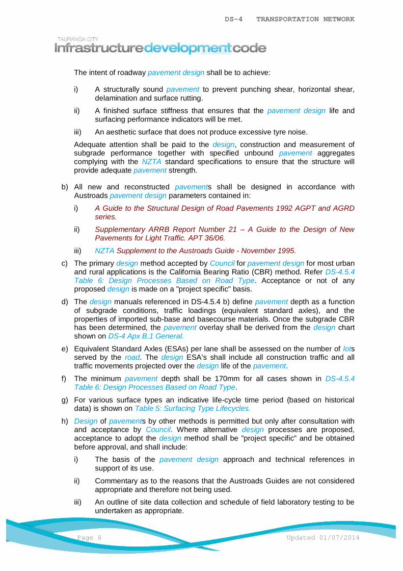
DS-4 TRANSPORTATION NETWORK
Page 8 Updated 01/07/2014
The intent of roadway pavement design shall be to achieve:
i) A structurally sound pavement to prevent punching shear, horizontal shear,delamination and surface rutting.
ii) A finished surface stiffness that ensures that the pavement design life andsurfacing performance indicators will be met.
iii) An aesthetic surface that does not produce excessive tyre noise.
Adequate attention shall be paid to the design, construction and measurement ofsubgrade performance together with specified unbound pavement aggregatescomplying with the NZTA standard specifications to ensure that the structure willprovide adequate pavement strength.
b) All new and reconstructed pavements shall be designed in accordance withAustroads pavement design parameters contained in:
i) A Guide to the Structural Design of Road Pavements 1992 AGPT and AGRDseries.
ii) Supplementary ARRB Report Number 21 – A Guide to the Design of NewPavements for Light Traffic. APT 36/06.
iii) NZTA Supplement to the Austroads Guide - November 1995.
c) The primary design method accepted by Council for pavement design for most urbanand rural applications is the California Bearing Ratio (CBR) method. Refer DS-4.5.4Table 6: Design Processes Based on Road Type. Acceptance or not of anyproposed design is made on a "project specific" basis.
d) The design manuals referenced in DS-4.5.4 b) define pavement depth as a functionof subgrade conditions, traffic loadings (equivalent standard axles), and theproperties of imported sub-base and basecourse materials. Once the subgrade CBRhas been determined, the pavement overlay shall be derived from the design chartshown on DS-4 Apx B.1 General.
e) Equivalent Standard Axles (ESAs) per lane shall be assessed on the number of lotsserved by the road. The design ESA’s shall include all construction traffic and alltraffic movements projected over the design life of the pavement.
f) The minimum pavement depth shall be 170mm for all cases shown in DS-4.5.4Table 6: Design Processes Based on Road Type.
g) For various surface types an indicative life-cycle time period (based on historicaldata) is shown on Table 5: Surfacing Type Lifecycles.
h) Design of pavements by other methods is permitted but only after consultation withand acceptance by Council. Where alternative design processes are proposed,acceptance to adopt the design method shall be "project specific" and be obtainedbefore approval, and shall include:i) The basis of the pavement design approach and technical references in
support of its use.
ii) Commentary as to the reasons that the Austroads Guides are not consideredappropriate and therefore not being used.
iii) An outline of site data collection and schedule of field laboratory testing to beundertaken as appropriate.
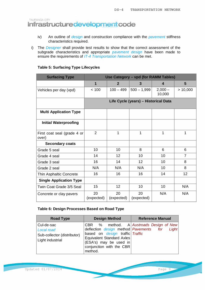
DS-4 TRANSPORTATION NETWORK
Updated 01/07/2014 Page 9
iv) An outline of design and construction compliance with the pavement stiffnesscharacteristics required.
i) The Designer shall provide test results to show that the correct assessment of thesubgrade characteristics and appropriate pavement design have been made toensure the requirements of IT-4 Transportation Network can be met.
Table 5: Surfacing Type Lifecycles
Surfacing Type Use Category – vpd (for RAMM Tables)1 2 3 4 5
Vehicles per day (vpd) < 100 100 – 499 500 – 1,999 2,000 –10,000
> 10,000
Life Cycle (years) – Historical Data
Multi Application Type
Initial Waterproofing
First coat seal (grade 4 orover)
2 1 1 1 1
Secondary coatsGrade 5 seal 10 10 8 6 6
Grade 4 seal 14 12 10 10 7
Grade 3 seal 16 14 12 10 8
Grade 2 seal N/A N/A N/A 10 8
Thin Asphaltic Concrete 16 16 16 14 12
Single Application TypeTwin Coat Grade 3/5 Seal 15 12 10 10 N/A
Concrete or clay pavers 20(expected)
20(expected)
20(expected)
N/A N/A
Table 6: Design Processes Based on Road Type
Road Type Design Method Reference ManualCul-de-sacLocal roadSub-collector (distributor)Light industrial
CBR % method. Adeflection design methodbased on design trafficEquivalent Standard Axles(ESA's) may be used inconjunction with the CBRmethod.
Austroads Design of NewPavements for LightTraffic

DS-4 TRANSPORTATION NETWORK
Page 10 Updated 01/07/2014
Heavy industrial/commercial roadPrincipal/collectorarterial road
Interlayer strain analysisby CIRCLY
Austroads 1962 –Structural Design of RoadPavements
DS-4.5.4.1 Determination of Subgrade Characteristics
The following shall apply:
a) For pavement design purposes the subgrade is defined as the block of soilpresent directly below the sub-base or basecourse layers to a depth of 500mm.
b) Subgrade characteristics for pavement design are not determined until landformearthworks have been undertaken and completed. For the purposes of approval,assumed values can be applied based on judgement and experience, on thebasis that confirmation tests and/or assessments are made to confirm thedesign when the pavement subgrade is exposed. Council shall be notified whenthe subgrade testing/assessments are to be made.
c) There are 3 predominant soil types in the City area which will comprise mostsubgrades:
i) Sands.
ii) Volcanic ash (being pumiceous sands, silts and clays).
iii) Peat or estuarine deposits (compressible soils).
d) Designers must be fully conversant with the sensitive nature of the volcanic ashsoils when subjected to traffic loading and shall take full account of thesecharacteristics in designing pavement thickness.
Important factors are:
i) The site soil/fill soil subgrade will be subjected to intensive constructiontraffic loading.
ii) Volcanic ash soils remould, lose shear strength and become more flexiblewith repeated traffic loading.
iii) Volcanic ash soils have an ability to substantially regain shear strengthand stiffness where, after remoulding, they are left in an un-traffickedstate. The time durations to achieve this vary according to the nature ofthe ash, its water content and permeability. The effect on the subgrade(which is negated in time) is due to the drainage of water used forbasecourse preparation into the subgrade.
iv) Measurement of the subgrade soil characteristics shall reflect thedisturbed remoulded characteristic.
v) Having subdivided the roadway into sections which are deemedhomogenous with respect to subgrade type, topography and drainage, adesign subgrade CBR value shall be determined by Insitu CBR tests usingthe tests required by IT- 4.2.1 Subgrade Testing Carriageways.
Note: The Scala Penetration Test that derives CBR parameters by reference to ad-hocrelationships between these properties is not acceptable for pavement design.
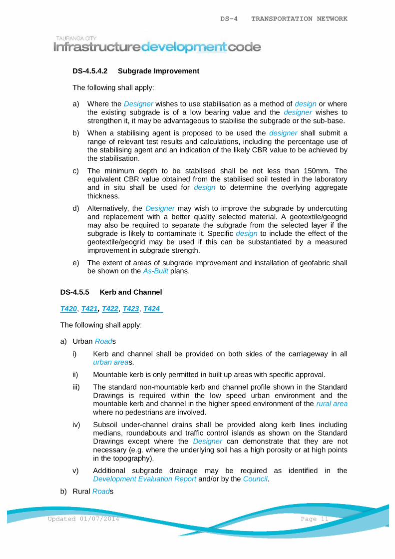
DS-4 TRANSPORTATION NETWORK
Updated 01/07/2014 Page 11
DS-4.5.4.2 Subgrade Improvement
The following shall apply:
a) Where the Designer wishes to use stabilisation as a method of design or wherethe existing subgrade is of a low bearing value and the designer wishes tostrengthen it, it may be advantageous to stabilise the subgrade or the sub-base.
b) When a stabilising agent is proposed to be used the designer shall submit arange of relevant test results and calculations, including the percentage use ofthe stabilising agent and an indication of the likely CBR value to be achieved bythe stabilisation.
c) The minimum depth to be stabilised shall be not less than 150mm. Theequivalent CBR value obtained from the stabilised soil tested in the laboratoryand in situ shall be used for design to determine the overlying aggregatethickness.
d) Alternatively, the Designer may wish to improve the subgrade by undercuttingand replacement with a better quality selected material. A geotextile/geogridmay also be required to separate the subgrade from the selected layer if thesubgrade is likely to contaminate it. Specific design to include the effect of thegeotextile/geogrid may be used if this can be substantiated by a measuredimprovement in subgrade strength.
e) The extent of areas of subgrade improvement and installation of geofabric shallbe shown on the As-Built plans.
DS-4.5.5 Kerb and Channel
T420, T421, T422, T423, T424
The following shall apply:
a) Urban Roads
i) Kerb and channel shall be provided on both sides of the carriageway in allurban areas.
ii) Mountable kerb is only permitted in built up areas with specific approval.
iii) The standard non-mountable kerb and channel profile shown in the StandardDrawings is required within the low speed urban environment and themountable kerb and channel in the higher speed environment of the rural areawhere no pedestrians are involved.
iv) Subsoil under-channel drains shall be provided along kerb lines includingmedians, roundabouts and traffic control islands as shown on the StandardDrawings except where the Designer can demonstrate that they are notnecessary (e.g. where the underlying soil has a high porosity or at high pointsin the topography).
v) Additional subgrade drainage may be required as identified in theDevelopment Evaluation Report and/or by the Council.
b) Rural Roads
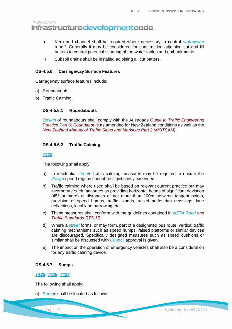
DS-4 TRANSPORTATION NETWORK
Page 12 Updated 01/07/2014
i) Kerb and channel shall be required where necessary to control stormwaterrunoff. Generally it may be considered for construction adjoining cut and fillbatters to control potential scouring of the water tables and embankments.
ii) Subsoil drains shall be installed adjoining all cut batters.
DS-4.5.6 Carriageway Surface Features
Carriageway surface features include:
a) Roundabouts.
b) Traffic Calming.
DS-4.5.6.1 Roundabouts
Design of roundabouts shall comply with the Austroads Guide to Traffic EngineeringPractice Part 6: Roundabouts as amended for New Zealand conditions as well as theNew Zealand Manual of Traffic Signs and Markings Part 2 (MOTSAM).
DS-4.5.6.2 Traffic Calming
T422
The following shall apply:
a) In residential streets traffic calming measures may be required to ensure thedesign speed regime cannot be significantly exceeded.
b) Traffic calming where used shall be based on relevant current practice but mayincorporate such measures as providing horizontal bends of significant deviation(45° or more) at distances of not more than 100m between tangent points,provision of speed humps, traffic islands, raised pedestrian crossings, lanedeflections, local lane narrowing etc.
c) These measures shall conform with the guidelines contained in NZTA Road andTraffic Standards RTS 15.
d) Where a street forms, or may form, part of a designated bus route, vertical trafficcalming mechanisms such as speed humps, raised platforms or similar devicesare discouraged. Specifically designed measures such as speed cushions orsimilar shall be discussed with Council approval is given.
e) The impact on the operation of emergency vehicles shall also be a considerationfor any traffic calming device.
DS-4.5.7 Sumps
T425, T426, T427
The following shall apply:
a) Sumps shall be located as follows:
DS-4 TRANSPORTATION NETWORK
Updated 01/07/2014 Page 13
i) On roads having a carriageway up to and including 11m wide and a maximumchannel run of 100m.
ii) On all roads with a carriageway greater than 11m wide and a maximumchannel run of 80m.
iii) On the high side of intersections located at the kerb line tangent point.
iv) At changes of gradient or direction in the channel where there could be atendency for water to leave the channel.
v) A double sump shall be installed to minimise the risk of ponding at cul-de-sacheads where there is a low point and at the lowest point in a sag vertical curvewhere the gradient exceeds 12%.
vi) Where longitudinal gradients of a carriageway exceed 12%, sumps shall belocated at a maximum of 80m intervals for carriageways up to and including10m wide and 65m intervals on wider carriageways and in all cases shall be ahigh capacity sump.
vii) Sumps shall not be located at the apex of a bend.
b) Where kerb and channel is utilised, sumps shall be recessed as shown in theStandard Drawings.
c) High Capacity Sumps (please refer to AM-4.14.5) are required in circumstanceswhere additional capacity is required to direct and manage stormwater, whereexcessive debris may be an issue or where the carriageway longitudinal gradient isvery steep (e.g. ≥12%) or very flat 0-3%).
d) Roads without kerb and channel shall have a specifically designed stormwatercatchment system subject to Council approval.
e) All sumps shall be connected to the primary stormwater system by a 300mmØminimum connection to an adjacent manhole.
f) If the adjacent stormwater system is larger than 600mmØ and the manhole is notconveniently located, the sump lead may be saddled directly to the pipe. Thisconnection shall be a minimum of 300mmØ.
g) Individual sumps or interconnected double sumps shall be connected separately to amanhole and not through a second sump system.
h) At all points where sump blockage or under-capacity could lead to overflow intoprivate property, the provision of designed secondary flowpaths protected by publicownership or easements shall be made. Refer to DS-5 Stormwater for details.
i) The following shall be considered when designing for sumps:
i) Stormwater flow characteristics
ii) Berm, Kerb, Channel and Carriageway Crossfall
iii) Safety
iv) Access for cleaning
v) Other environmental factors specific to the site that may influencefunctionality
a) Unless specific capacity of a sump is known or derived from first principles, thedesign capacity of a single back entry sump with standard grating shall belimited to 28 L/s.

DS-4 TRANSPORTATION NETWORK
Page 14 Updated 01/07/2014
j) The type, specification and selection criteria for each sump shall be submitted toCouncil for approval.
k) Sumps shall be constructed to ensure optimal functionality e.g sump grates andbackdrops match the kerb and carriageway gradients.
DS-4.5.8 Carriageway Surfacing
Carriageways shall be surfaced with bituminous seal unless otherwise approved byCouncil.
DS-4.5.8.1 Hot-laid Asphaltic Concrete (asphalt)
The following shall apply:
a) All arterial and collector roads, including cul-de-sac heads, turning areas,roundabouts, approaches and industrial intersections shall be surfaced withasphaltic concrete unless otherwise approved by Council.
b) As asphaltic concrete is not in itself completely waterproof, a first coat seal orsimilar shall be required to provide an initial waterproofing layer.
c) When a membrane seal is used, a minimum of 1.0 L/m² of residual penetrationgrade bitumen shall be required. The manufacturers recommended time shallelapse between the first coat seal and the laying of asphaltic concrete to ensureadequate curing of the binder.
d) When using NZTA Specification M10 compliant mixes on roads with an ADTgreater than 100vpd, NZTA guidelines on skid resistance and surface textureshall be incorporated in the mix design.
e) Non-structural asphalt layers are not considered to be part of the structuralpavement design.
DS-4.5.8.2 Two Coat Seal (First Coat with Wet Locking Coat)
The following shall apply:
a) Except where otherwise approved by Council, basic carriageway surfacing shallbe a first coat chip seal, followed by a second coat chip seal after 12 months.
b) Generally, the first coat shall use Grade 3 chip and the second coat shall use achip size between Grade 4 and Grade 5 as appropriate to the location.
c) A two coat seal as a first coat does not remove the need for a second coat seal.
Refer to the NZTA Manual Chipsealing in New Zealand for further chipsealdesign parameters.
DS-4.5.8.3 Interlocking Concrete Block Paving
In general, block paving shall not be permitted as a carriageway surfacing materialunless otherwise approved by Council.
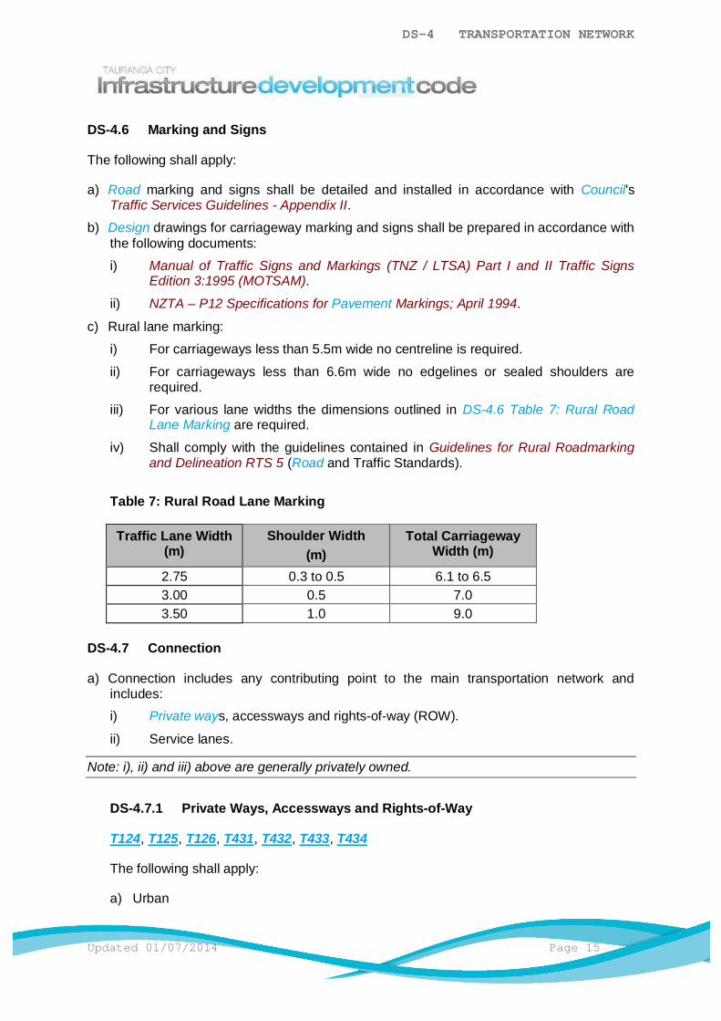
DS-4 TRANSPORTATION NETWORK
Updated 01/07/2014 Page 15
DS-4.6 Marking and Signs
The following shall apply:
a) Road marking and signs shall be detailed and installed in accordance with Council'sTraffic Services Guidelines - Appendix II.
b) Design drawings for carriageway marking and signs shall be prepared in accordance withthe following documents:
i) Manual of Traffic Signs and Markings (TNZ / LTSA) Part I and II Traffic SignsEdition 3:1995 (MOTSAM).
ii) NZTA – P12 Specifications for Pavement Markings; April 1994.
c) Rural lane marking:
i) For carriageways less than 5.5m wide no centreline is required.
ii) For carriageways less than 6.6m wide no edgelines or sealed shoulders arerequired.
iii) For various lane widths the dimensions outlined in DS-4.6 Table 7: Rural RoadLane Marking are required.
iv) Shall comply with the guidelines contained in Guidelines for Rural Roadmarkingand Delineation RTS 5 (Road and Traffic Standards).
Table 7: Rural Road Lane Marking
Traffic Lane Width(m)
Shoulder Width(m)
Total CarriagewayWidth (m)
2.75 0.3 to 0.5 6.1 to 6.53.00 0.5 7.03.50 1.0 9.0
DS-4.7 Connection
a) Connection includes any contributing point to the main transportation network andincludes:i) Private ways, accessways and rights-of-way (ROW).
ii) Service lanes.
Note: i), ii) and iii) above are generally privately owned.
DS-4.7.1 Private Ways, Accessways and Rights-of-Way
T124, T125, T126, T431, T432, T433, T434
The following shall apply:
a) Urban
DS-4 TRANSPORTATION NETWORK
Page 16 Updated 01/07/2014
i) Shall be constructed in accordance with the Standard Drawings unlessotherwise approved by Council.
ii) Shall have a properly formed and sealed carriageway as per the StandardDrawings and shall be surfaced with asphaltic concrete, 2 Coat Chip Seal,concrete block paving or cast insitu concrete.
iii) Coloured concrete, exposed aggregate and decorative aggregate surfacesmay be acceptable upon approval by Council.
iv) Stamped and imprinted concrete is not acceptable for accessways orright-of-ways.
v) For private ways serving up to three dwellings vehicular access may beprovided by concrete strips. Two concrete strips 750mm wide by 130mm thickwith a 750mm central space between are acceptable.
vi) Kerbs may be mountable but provision shall be made to control and dispose ofstormwater. This may require non-mountable kerbs or raised berms to controloverland flow between adjacent lots.
vii) A standard urban vehicle crossing shall be provided.
viii) Stormwater drainage shall be provided by use of 450mm x 450mm sump orsimilar as approved by Council and 225mmØ discharge so that the maximum"run of water" does not exceed 90m and/or the area served by each sumpshall not exceed 300m².
ix) Specific design for stormwater drainage shall be required if the longitudinalgradient exceeds 12%.
x) The maximum gradient shall be 20% (1V:5H). Restrictions exist on the lengthsand widths of urban privateways as in DS-4.5.1.1 Table 1: DesignRequirements for Various Road Classifications.
b) Rural
i) Shall be constructed in accordance with the Standard Drawings unlessotherwise approved by Council.
ii) Shall have a properly formed and sealed carriageway as per the StandardDrawings and shall be surfaced with asphaltic concrete, 2 Coat Chip Seal,concrete block paving or cast insitu concrete.
iii) Coloured concrete, exposed aggregate and decorative aggregate surfacesmay be acceptable upon approval by Council.
iv) Stamped and imprinted concrete is not acceptable for accessways orright-of-ways.
v) Where the City Plan permits and subject to appropriate approval from otherusers and adjacent property owners the carriageway surface may be formedfrom compacted basecourse.
vi) Where new privateways are created, cut or fill batters shall be outside theprivateway boundary. For the formation of privateways in existing easements,the formation shall occur through the centre of the reserve and all cut or fillbatters steeper than 1V:4H shall be contained outside the existing easement.Culverts may be included within the privateway width where possible.
vii) A standard rural vehicle crossing shall be provided for each rural private way.
DS-4 TRANSPORTATION NETWORK
Updated 01/07/2014 Page 17
viii) For private ways serving up to three dwellings vehicular access may beprovided by concrete strips. Two concrete strips 750mm wide by 130mm thickwith a 750mm central space between are acceptable.
ix) Passing bays shall be formed at not more than 150m intervals and shallprovide practical access for one 90 percentile car to park while another vehiclepasses. These shall logically be located at one of the following:
a) Entrances off the private way.
b) At bends where sight distances allow.
c) At widened sections of the carriageway to the dimensions shown on theStandard Drawings.
d) Within the reserve width available.
x) Passing bays shall be finished with the same surface as the right-of-waysurface. The surface crossfall from the passing bay shall be a continuation ofthe crossfall on the private way surface.
DS-4.7.2 Commercial Service Lanes
T113
The following shall apply:
a) Where a commercial development is to be provided with access by means of aservice lane it shall consist of a minimum carriageway width of 5.5m with kerb andchannel both sides.
b) Consideration may be given in special circumstances (dictated by topography) toproviding kerb and channel on one side only. Kerb and channel may be mountablewith provision for sumps for stormwater removal.
c) A minimum compacted depth of basecourse of 150mm shall be constructed on asubgrade with a minimum CBR of 7 or more and a minimum of asphaltic concreteseal is required.
d) For swept path design criteria refer to New Zealand on Road Tracking Curvespublished by LTSA (August 2007) as RTS 18.
DS-4.7.3 Industrial Service Lanes
T113
The following shall apply:
a) Where a service lane serves properties on one side only the carriageway surfacemay have a single cross-fall with kerb and channel on the lower side and a concreteedging strip flush with the surface on the high side. Otherwise the service lane shallbe constructed with a central crown and with kerb and channel both sides.
b) A minimum compacted depth of basecourse of 250mm shall be constructed on asubgrade with a minimum CBR of 7 or more. A minimum of asphaltic concrete seal isrequired.
DS-4 TRANSPORTATION NETWORK
Page 18 Updated 01/07/2014
c) Specific requirements may also call for the provision of passing bays and/or turningcircles.
d) Grades shall not be less than 0.5% (1:200) or exceed 12.5% (1:8).
e) For swept path design refer to New Zealand on Road Tracking Curves published byLTSA (August 2007) as RTS 18.
DS-4.8 Berm Features
The berm is the width of land located between the edge of the carriageway and the propertyboundary.
Berm features include:
a) DS-4.8.1 Vehicle Crossings and Entrances.
b) DS-4.8.2 Footpaths.
c) DS-4.8.3 Cycle Paths.
d) DS-4.8.4 Pedestrian Accessways.
DS-4.8.1 Vehicle Crossings and Entrances
T124, T125, T126, T431, T432, T433, T434
The following shall apply:
a) Urban
i) A vehicle crossing shall be provided between the kerb and the boundary for alllots, private ways and service lanes.
ii) The vehicle crossing shall be located at the entrance to all entrance strips torear lots where the location of this is known.
iii) Vehicle crossings shall be designed to ensure the safety of pedestrians and allroad users. Designs shall ensure that no damage occurs to vehicles, thecarriageway, the vehicle crossing/footpath or the driveway/privateway.
Designs shall be submitted to Council for approval and include:
a) The proposed location and dimensions of the vehicle crossing.
b) The location of all existing infrastructure services.
c) The location of known future infrastructure services.
d) Tree locations and other above ground sight obstructions.
e) Vertical profiles from the centreline of the road to the boundary where thecarriageway crossfall "rolls over" i.e. is not at a consistent grade, and/or isgreater than 3%.
f) Vertical profiles from the centreline of the road to the parking platform wherethe parking platform is accessed at a grade above 1 in 4 from the boundary(upslope or downslope) or where the existing profile is such that therequirements of Council's Standard Drawings can not be met.
DS-4 TRANSPORTATION NETWORK
Updated 01/07/2014 Page 19
g) Horizontal profiles for a 90% Car shall be provided for all vehicle crossingsconstructed on a Collector Road and any road of higher hierarchy. Thedesign shall be to ensure that vehicles exiting the property can do so "frontfirst". Reversing from properties onto these roads is not permitted for safetyreasons.
iv) Vehicle crossings shall be constructed as per the Standard Drawings andcomply with standard sight distance requirements contained in the AustroadGuides.
v) Any existing vehicle crossings located on unformed roads shall be constructedat the existing location and grades in accordance with Council’s standardspecification when the road is formed unless specific agreement for relocatingthose vehicle entrances has been negotiated between the developer and theexisting landowner.
vi) An alternative crossing construction using stamped, coloured or stencilledconcrete, asphalt or interlocking concrete block may be used between thefootpath and boundary.
vii) Vehicle crossings provided in areas where there is no kerb and channel shallconform with the Standard Drawing for rural entrances.
b) Rural
i) Vehicle crossings provided on rural areas shall be constructed as per theStandard Drawings.
ii) Any further design requirements shall be as detailed in the latest operativerevision of the Western Bay of Plenty District Council’s Development Code ofPractice upon agreement with Tauranga City Council.
DS-4.8.2 Footpaths
The following shall apply:
a) Where the carriageway is less than 9m wide a footpath shall be required on one sideof the carriageway only.
b) Where the carriageway is more than 9m wide a footpath shall be required on bothsides of the carriageway.
c) The footpath shall be located as shown on the Standard Drawings.
d) Additional width may be required where angle parking adjacent to the footpath isanticipated.
e) Footpaths shall be clear of all obstructions, i.e., streetlights, street and traffic signs.Extra widening may be required at the request of Council.
f) A footpath shall generally be concrete, 1.5m wide with a minimum 28-day strength of17.5MPa and with a minimum thickness of 100mm on a compacted subgrade.
g) Footpaths shall be constructed as a continuous concrete pathway across privatedriveways and formed vehicle crossings with a depth of 125mm in residential areas.
h) Alternative surfacing materials may be used for footpaths only where approved byCouncil. This may include concrete pavers and asphaltic concrete to a minimumthickness of 25mm. Any alternative surfacing material must be demonstrated to beappropriate to the surrounding environment.

DS-4 TRANSPORTATION NETWORK
Page 20 Updated 01/07/2014
i) All areas between the kerb line and the boundary that are not paved shall have aminimum cross-fall of 2% (maximum 5%) falling towards the kerb and shall befinished with topsoil and sown with grass in accordance with:
i) DS-2 – Streetscape.
ii) CS-23 Grassing and Turfing.
DS-4.8.2.1 Industrial and Commercial Footpaths
The following shall apply:
a) Footpaths in industrial and commercial areas shall be constructed of concrete to125mm thickness by Council after the building development has taken place. Tofacilitate this, the Consent Holder shall pay to the Council a sum of money asmay be determined by Council to cover the cost of providing the concretefootpath as required.
b) Footpaths shall be constructed as a continuous concrete pathway across privatedriveways and formed vehicle crossings with a depth of 150mm in industrial andcommercial areas.
DS-4.8.2.2 Pathway Kerb Crossings
T440
The following shall apply:
a) A mobility crossing (pram crossing) shall be provided at all road intersectionsand such other locations to provide for logical and safe movements ofpedestrians.
b) The maximum gradient of any mobility crossing shall be 1:12 in accordance withSNZ 8630:2004 to provide for access for disabled people.
c) All mobility crossings and associated infrastructure shall comply with NZTARoad and Traffic Standards RTS 14, Guidelines for Facilities for Blind andVision Impaired Pedestrians.
DS-4.8.2.3 Tactile Paving
CBD442
The following shall apply:
a) Colour of paving is Yellow. Alternative colours maybe considered subject toCouncil approval. The colour shall be consistent throughout each adjoiningpaver for each installation i.e. the same exact match of colour, not a mix ofcolours.
b) Concrete Paver thickness of 60mm or alternative tactile studs may be saw cut ordrilled in place.
c) Friction coefficient shall be a minimum of 70 using the Wet Pendulum SlipResistance Test HSE UK.
DS-4 TRANSPORTATION NETWORK
Updated 01/07/2014 Page 21
d) The requirements of NZS 4121:2001 Design for Access and Mobility - Buildingsand associated facilities, NZTA Pedestrian Planning and Design Guide andRoad and Traffic Guidelines RTS 14, Guidelines for Facilities for Blind andVision Impaired Pedestrians shall be followed where not superseded by the IDC.
e) All installations shall carry a 2 year installation Warranty
f) Suppliers shall provide evidence in the form of a report on the following for eachinstallation:
i) Coefficient of Friction
ii) UV Resistance & Colour Fastness
iii) Abrasion Resistance
iv) Resistance to Hydrolysis and Microbial Attack
DS-4.8.3 Cycle Paths
T123, T440, T442
The following shall apply:
a) Where required, off-carriageway paths for cycle use shall be provided as sharedpedestrian/cyclist facilities and shall be to standards specified for footpaths.
b) Width requirements shall be as shown on the Standard Drawings.
c) The shared path shall be at a maximum gradient of 12.5% and have a minimumlateral clearance of 700mm and a minimum overhead clearance of 2.5m from anyfixed object (including trees). Extra widening may be required at the request ofCouncil.
d) Stormwater disposal, fencing, handrails and lighting shall be provided as appropriateto each specific situation.
e) The design shall also comply with Austroads Guide to Engineering Practice Part 14Bicycles and the New Zealand supplement current at the time of design.
f) Alternative surfacing materials may be used for cycle paths only where approved byCouncil. Alternative materials may include concrete pavers and asphaltic concrete toa minimum thickness of 25mm. Any alternative surfacing material must bedemonstrated to be appropriate to the surrounding environment.
g) When planning and designing routes for cycle paths approval shall be obtained fromCouncil before the application for Resource Consent.
DS-4.8.4 Pedestrian Accessways
T123
The following shall apply:
DS-4 TRANSPORTATION NETWORK
Page 22 Updated 01/07/2014
a) Pedestrian accessways shall be as short as possible with a clear line of sight throughtheir length and be generally constructed in accordance with the Standard Drawingswhich represents a minimum standard. Alternative specific designs for both the pathand fencing are encouraged to enhance the visual amenity values of theaccessways.
b) The topography of the land and Crime Prevention Through Environmental Design(CPTED) principles shall also be considered during design.
c) Provision shall be made for disposal of stormwater flowing down the length of theaccessway to prevent discharge across the road footpath.
d) Pedestrian accessways shall not be steeper than 12.5%. Where the ruling gradient issteeper, steps and combinations of steps and a graded path may be necessary.
e) Where a significant amount of surface water will be concentrated by the footpath in apedestrian accessway (where the length of footpath exceeds 10m), it shall becollected by a dished channel and disposed of through a 450mm x 450mm sump(s)or an approved alternative with a maximum run of 60m.
DS-4.8.5 Alternative Method – Interlocking Paving Blocks
The following shall apply:
a) Interlocking concrete block paving will only be considered on a case by case basisonly as approved by Council.
b) The paving shall be specifically designed and laid generally in accordance with NZS3116 for concrete segmental paving.
c) Manufacture, testing, acceptance and supplies of concrete segmental pavers shallcomply with AS/NZS 4455 and AS/NZS 4456. Paving units shall have in-builtseparators.
d) Periodic additional sanding/filling of joints and attention to excessive settlement ormovement may be required during the 12 month defects liability period.
e) When using paving stones particular attention shall be given to subsoil drainage andretaining a dry subgrade.
f) The minimum length of block paving shall be 20m. Narrow bands of block paving atthresholds or roundabout approaches are not permitted.
g) The materials shall be consistent with adjacent roads and conform to localstreetscape themes.
h) Paving construction shall be undertaken by a Council approved paver.
DS-4.9 Further Considerations
The following shall also be considered as part of the design process:
a) DS-4.9.1 Bridges.
b) DS-4.9.2 Culverts.c) DS-4.9.3 Urban Roadside Barriers and Guardrail Design.d) DS-4.9.4 Streetscaping.
DS-4 TRANSPORTATION NETWORK
Updated 01/07/2014 Page 23
e) DS-4.9.6 Network Utilities.f) DS-4.9.7 Road Zone Occupancy.
DS-4.9.1 Bridges
The following shall apply:
a) Concept approval is required from Council before undertaking bridge design.
b) Detailed design shall be required at the time of Development Works Approval. Whereno Development Works Approval is required as part of a Resource Consent, thenCouncil approval shall be obtained at a time required by Council and beforeconstruction of the system.
c) Bridge design shall conform with the technical requirements of NZTA Bridge DesignManual and be undertaken by an appropriately qualified Chartered ProfessionalEngineer. Reference shall also be made to the Austroad Guides AGBT series forbridge technology.
d) The width between kerbs and wheel guards shall be in accordance with the NZTABridge Design Manual.
e) All bridges, box culverts and other culverts over 1.0mØ may be subject to a buildingconsent under the Building Act.
f) Bridges shall be designed to:
i) Be capable of carrying a design loading of HN-HO-72 (public road bridges).
ii) Be capable of carrying a design loading of 0.85 (HN-72) (private road bridges)and as shown in the TNZ Bridge Manual: Appendix D :Lightly Trafficked RuralBridges, June 2003.
iii) Have bridge clearances to waterways that shall be approved by Bay of PlentyRegional Council but shall provide not less than 600mm freeboard for a 1%AEP flood event.
iv) Provide full clearance for the passage of all vehicles permitted to operate onpublic roads under the Transport Act 1962, when bridges are provided abovetraffic lanes.
v) Provide safe passage of all pedestrians and cyclists.
g) Where bridges exist along private way/ROW alignments that are to be upgraded forprivate ways approved as a condition of Resource Consent, the bridge shall beexamined by a Chartered Professional Engineer who shall determine:
i) The capability of the bridge structure and foundations to support the designloadings (or restricted loadings).
ii) The serviceability of the structure and what measures may be required toupgrade the bridge to last another 50 years.
iii) Appropriate signs to advise of loading and speed limitations.h) In some circumstances on private ways an alternative crossing such as a ford may
be required for vehicles which exceed width or loading limitations.
DS-4 TRANSPORTATION NETWORK
Page 24 Updated 01/07/2014
i) For a culvert, the design shall allow for the passage of a 10 year flood event withoutheading up, and for a 100-year flood by heading up to a maximum level 0.5m belowthe road surface as per the NZTA Bridge Manual.
j) For roads with a use of less than 750vpd as a minimum, the design shall allow forthe passage of a 10 year flood and heading up to a maximum level of 0.5m belowthe road surfaces and for a 100 year flood by overtopping the embankment to amaximum depth of 0.2m. Where the road crosses a defined flood plain andovertopping is to be provided for, specific design shall be provided to the satisfactionof Council. If the heading up condition is considered, the design shall ensureembankment stability under flood conditions and adequate protection to safeguardagainst piping. This clause includes accessways and rights of\- way. Heading upshall be considered in all cases where fallen trees are able to enter the water course.
k) In all cases where heading up or overtopping is a design feature, attention shall begiven to back water effects upstream to ensure that adjoining land is not adverselyaffected by flooding.
l) Culverts beneath carriageways shall not be less than 300mmØ.
m) Installation of bridges or culverts on natural watercourses are generally subject to aBay of Plenty Regional Council Resource Consent or, in some cases, the works maybe covered as a Permitted Activity. Design and construction of these shall complywith all requirements of the Resource Consent or permitted activity criteria.
The advice of Bay of Plenty Regional Council shall be sought at an early stage in thedesign process.
n) For roads to be vested in Council, existing bridges or culverts not meeting thisstandard shall be upgraded to the standard or replaced with structures complyingwith the standard.
DS-4.9.2 Culverts
T443
The following shall apply:
a) Culverts shall cross the road as directly as possible and in no case at less than 60°to the road centreline.
b) The inlet and outlet of the culvert shall be at least 1.5m beyond the feather edge andpreferably further to reduce the traffic hazard and provide adequate support to theroad shoulder.
c) Culverts shall be reinforced concrete. Where alternate materials are being proposed,this will require specific approval from Council.
d) Care shall be taken to prevent scour in channels downstream of culvert outfalls andthe construction of stormwater fluming may be necessary. Where culvert or road cutout discharges are to occur into private land, the written approval of the privatelandowner shall be obtained before construction and evidence of this provided toCouncil.

DS-4 TRANSPORTATION NETWORK
Updated 01/07/2014 Page 25
e) If necessary a stormwater treatment device designed and installed in accordancewith the Auckland Regional Council Technical Publication 10 Design Guidelines forStormwater Treatment Devices or other accepted design procedures may benecessary until the upstream catchment road works have stabilised.
DS-4.9.3 Urban Roadside Barriers and Guardrail Design
The following shall apply:
a) NZTA Road and Traffic Standards RTS 11 – Urban Roadside Barriers andAlternative Treatments shall be the basis for urban guardrail design.
b) Guardrails shall be designed by an experienced Chartered Professional Engineer inaccordance with the current NZTA Specification M23 and the current State HighwayGeometric Design Manual. The end assembly shall comply with NZHRP 350 TL-3unless specifically approved by the Council.
c) Where roads, private ways or other vehicular or pedestrian access, whether public orprivate, run parallel with land which drops on one or both sides, the sides shall beprovided with safety barriers to protect pedestrian or vehicular traffic.
d) Safety barriers for pedestrian access shall comply with the design requirements ofthe Approved Document D1 of the New Zealand Building Code as referred to in NZS4404.
e) All signage shall comply with the Traffic Control Devices Rule 54002.
DS-4.9.4 Streetscaping
Refer to:
a) DS-2 Streetscape.
DS-4.9.5 Streetlighting and Traffic Signals
The following shall apply:
a) The design of traffic signals for local roads shall follow the requirements of theCouncil Traffic Systems Design and Implementation Guidelines. Where not specifieda recognised design standard and/or design method approved by Council shall beutilised.
b) For traffic signals on state highways, discussion shall be held with NZTA and theirrequirements met.
DS-4.9.6 Network Utilities
Refer to:
a) DS-9 Network Utilities.

DS-4 TRANSPORTATION NETWORK
Page 26 Updated 01/07/2014
DS-4.9.7 Road Zone Occupancy
All works within an existing Road Zone are subject to the requirements of:
a) DS-11 Road Zone Occupancy.
DS-4 TRANSPORTATION NETWORK
Updated 01/07/2014 Page 27
DS-4 - Appendix AAssociated Standards
DS-4 - Appendix A.1 General
The latest revision or operative version of the following standards shall be used inconjunction with the IDC:
a) Council documentation:
i) City Plan.
ii) TCC Transportation Guidelines.
iii) TCC Cycle Design Guidelines.
iv) TCC Traffic Systems Design and Implementation Guidelines
Note: Special consideration shall be given to the Streetscape, Stormwater and RoadZone Occupancy sections of the IDC.
b) New Zealand Transport Agency (NZTA) Standards:
i) Austroads Design Guides.
ii) Basecourse:
B/02NZTASpecificationB/02 NotesB/5B/5 NotesB/5 Changes
Construction of Unbound Granular Pavement Layers.Construction of Unbound Granular Pavement Layers.Specification for In-situ Stabilisation of Modified Pavement Layers.Notes to Specification for In-situ Stabilisation of Modified PavementLayers.Changes to B/5 Specification for In-situ Stabilisation of ModifiedPavement Layers.
20052005200820082008
iii) Formation:
F/1 Earthworks Construction. 1997F/1 Notes Earthworks Construction. 1997F/2 Pipe Subsoil Drain Construction. 2000F/2 Notes Pipe Subsoil Drain Construction. 2000F/3 Pipe Culvert Construction. 2000F/3 Notes Pipe Culvert Construction. 2000F/4 Notes Fence Construction May. 1975F/5 Corrugated Plastic Pipe Subsoil Drain Construction. 2000F/5 Notes Corrugated Plastic Pipe Subsoil Drain Construction. 2000F/6 Fabric Wrapped Aggregate Subsoil Drain Construction. 2003F/6 Notes Fabric Wrapped Aggregate Subsoil Drain Construction. 2003F/7 Geotextiles. 2003F/7 Notes Geotextiles. 2003

DS-4 TRANSPORTATION NETWORK
Page 28 Updated 01/07/2014
iv) Paving and Surfacing and Construction:
P/3 First Coat Sealing. 1995P/3 Notes First Coat Sealing. 1989P/4 Resealing. 1995P/4 Notes Resealing. 1989P/5P Rubber Latex in Reseal Binders. 1985P/5P Notes Rubber Latex in Reseal Binders. 1985P/9 Construction of Asphaltic Concrete Paving. June 1975P/9P (Auckland) Construction of Asphaltic Concrete Paving. Nov 1992P/11 Open Graded Porous Asphalt. 2007P/11 Notes Open Graded Porous Asphalt. 2007P/11 Changes Changes to Open Graded Porous Asphalt. 2007P/12 Pavement Marking. 2000P/12 Notes Pavement Marking. 1998P/14 Installation of Raised Pavement Markers. 1995P/14 Notes Installation of Raised Pavement Markers. 1995P/16 Installation of Edge Marker Posts. 1993P/16 Notes Installation of Edge Marker Posts 1992P/17 Performance Based Specification for Bituminous Reseals 2002P/17 Notes Performance Based Specification for Bituminous Reseals 2002P/21 Performance Based Specification for Edge Marker Posts 2003P/21 Notes Notes for the Performance Based Specification for Edge Marker Posts 2003P/22 Reflectorised Pavement Marking 2006P/23 Performance Based Specification for Hotmix Asphalt Wearing Course
Surfacing2005
P/23 Notes Notes to the Performance Based Specification for Hotmix AsphaltWearing Course Surfacing.
2005
P/24 Performance Based Specification for Traffic Signs. 2008P/24 Notes Notes for the Performance Based Specification for Traffic Signs. 2008P/26 Improvement of Pavement Macrotexture by use of High Pressure Water
and Grooving.2003
P/26 Notes Improvement of Pavement Macrotexture by use of High Pressure Waterand Grooving.
2003
P/28 Maintenance and Installation of Inductive Loops at Traffic MonitoringSites.
Nov 2006
P/30 High Performance Roadmarking. Jan 2009P/30 Notes High Performance Roadmarking. Jan 2009
v) Quality Assurance:
QG Notes Guideline on Roles in Quality Assurance. 1996Q/1 Chipsealing. 1995
DS-4 TRANSPORTATION NETWORK
Updated 01/07/2014 Page 29
Q/2 Hot Mix Asphalt. 1995Q/1 Notes andQ/2 Notes
Chipsealing and Hot Mix Asphalt. June 1995
Q/3 Normal QA Level Contracts. 1995Q/4 High QA Level Contracts. 1995Q/3 and Q/4Notes
Normal and High QA Level Contracts. 1995
vi) Standards:
S/5P Concrete Weigh Pit. 1987S/5P Notes Concrete Weigh Pit. 1987S6 Bridge and other Structures Inspection Policy. 2009
vii) Testing:
T/1 Benkelman Beam Deflection Measurements. June 1977
T/3 Measurement of Texture by the Sand Circle Method. 1981T/4 Description of Test Locations on Highways. 1981T/5 Size, Shape and Grading of Grades 1-4 Sealing Chips. 1987T/6 Pore Size Distributions of Filter Fabric. 1986T/7 Permeability of Filter Fabrics. 1983T/8 Roadmarking Paint Applicator Testing September. 2008T/8 Changes Changes to Roadmarking Paint Applicator Testing. Sept 2008T/9 Procedure for the Estimation of the Kerosene Content. 2003T/10 Skid Resistance Deficiency Investigation and Treatment Selection. 2002T/10 Notes Notes Skid Resistance Deficiency Investigation and Treatment
Selection.2002
T/11 Determination of the Permeability of Hot Mix Asphalt Pavements. 2003T/12 Long-Life Pavement Marking Material Applicator Testing. 2003T/12 Notes Long-Life Pavement Marking Material Applicator Testing. 2003
viii) Maintenance:
C Series toSOMAC
Changes. 2006
C Series toSOMAC
List and Disclaimer. 2006
C1 General Maintenance. 1995C1 AddendumNo 1
1997 to the Specification for General Maintenance. 1997
C1 Notes General Maintenance. 1995C3 Repair Potholes.
Replaced 2006.1993
C3 Notes Repair Potholes. 1993C3 Repair Potholes Replacement. 2006

DS-4 TRANSPORTATION NETWORK
Page 30 Updated 01/07/2014
ReplacementC4 Digout Repairs in Flexible Pavements.
Replaced 2006.1995
C4 Notes Digout Repairs in Flexible Pavements. 1993C4Replacement
Digout Repairs in Flexible Pavements Replacement. 2006
C5 Repair of Surface Openings and Minor Surface Levelling.Replaced 2006.
1993
C5 Notes Repair of Surface Openings and Minor Surface Levelling. 1992C5Replacement
Repair of Surface Openings and Minor Surface Levelling Replacement. 2006
C6 Repair of Surface Defects.Replaced 2006.
1995
C6 Notes Repair of Surface Defects 1992C6Replacement
Replacement Repair of Surface Defects Replacement. 2006
C7 Repair of Edge Break.Replaced 2006.
1995
C7 Notes Repair of Edge Break. 1992C7Replacement
Repair of Edge Break Replacement. 2006
C8 Adjusting Surface Boxes.Replaced 2006.
1992
C8 Notes Adjusting Service Corners. 1992C8Replacement
Adjusting Surface Boxes Replacement. 2006
C9 Emergency Work.Replaced 2006.
1995
C9 Notes Emergency Work. 1992C9Replacement
Emergency Work Replacement. 2006
C10 Maintenance of Unsealed Shoulders.Replaced 2006.
1995
C10 Notes Maintenance of Unsealed Shoulders. 1992C10Replacement
Maintenance of Unsealed Shoulders Replacement. 2006
C15 Removal of Surface Detritus.Replaced 2006.
1993
C15 Notes Removal of Surface Detritus. 1992C15Replacement
Removal of Surface Detritus Replacement. 2006
C16 Maintenance of Stormwater Structures. 1992
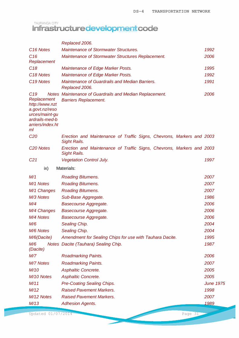
DS-4 TRANSPORTATION NETWORK
Updated 01/07/2014 Page 31
Replaced 2006.C16 Notes Maintenance of Stormwater Structures. 1992C16Replacement
Maintenance of Stormwater Structures Replacement. 2006
C18 Maintenance of Edge Marker Posts. 1995C18 Notes Maintenance of Edge Marker Posts. 1992C19 Notes Maintenance of Guardrails and Median Barriers.
Replaced 2006.1991
C19 NotesReplacementhttp://www.nzta.govt.nz/resources/maint-guardrails-med-barriers/index.html
Maintenance of Guardrails and Median Replacement.Barriers Replacement.
2006
C20 Erection and Maintenance of Traffic Signs, Chevrons, Markers andSight Rails.
2003
C20 Notes Erection and Maintenance of Traffic Signs, Chevrons, Markers andSight Rails.
2003
C21 Vegetation Control July. 1997
ix) Materials:
M/1 Roading Bitumens. 2007M/1 Notes Roading Bitumens. 2007M/1 Changes Roading Bitumens. 2007M/3 Notes Sub-Base Aggregate. 1986M/4 Basecourse Aggregate. 2006M/4 Changes Basecourse Aggregate. 2006M/4 Notes Basecourse Aggregate. 2006M/6 Sealing Chip. 2004M/6 Notes Sealing Chip. 2004M/6(Dacite) Amendment for Sealing Chips for use with Tauhara Dacite. 1995M/6 Notes(Dacite)
Dacite (Tauhara) Sealing Chip. 1987
M/7 Roadmarking Paints. 2006M/7 Notes Roadmarking Paints. 2007M/10 Asphaltic Concrete. 2005M/10 Notes Asphaltic Concrete. 2005M/11 Pre-Coating Sealing Chips. June 1975M/12 Raised Pavement Markers. 1998M/12 Notes Raised Pavement Markers. 2007M/13 Adhesion Agents. 1989
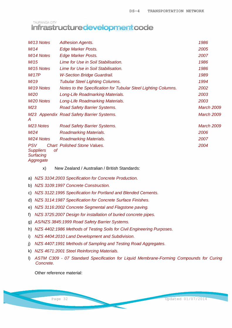
DS-4 TRANSPORTATION NETWORK
Page 32 Updated 01/07/2014
M/13 Notes Adhesion Agents. 1986M/14 Edge Marker Posts. 2005M/14 Notes Edge Marker Posts. 2007M/15 Lime for Use in Soil Stabilisation. 1986M/15 Notes Lime for Use in Soil Stabilisation. 1986M/17P W-Section Bridge Guardrail. 1989M/19 Tubular Steel Lighting Columns. 1994M/19 Notes Notes to the Specification for Tubular Steel Lighting Columns. 2002M/20 Long-Life Roadmarking Materials. 2003M/20 Notes Long-Life Roadmarking Materials. 2003M23 Road Safety Barrier Systems. March 2009M23 AppendixA
Road Safety Barrier Systems. March 2009
M23 Notes Road Safety Barrier Systems. March 2009M/24 Roadmarking Materials. 2006M/24 Notes Roadmarking Materials. 2007PSV ChartSuppliers ofSurfacingAggregate
Polished Stone Values. 2004
x) New Zealand / Australian / British Standards:
a) NZS 3104:2003 Specification for Concrete Production.
b) NZS 3109:1997 Concrete Construction.
c) NZS 3122:1995 Specification for Portland and Blended Cements.
d) NZS 3114:1987 Specification for Concrete Surface Finishes.
e) NZS 3116:2002 Concrete Segmental and Flagstone paving.
f) NZS 3725:2007 Design for installation of buried concrete pipes.
g) AS/NZS 3845:1999 Road Safety Barrier Systems.
h) NZS 4402:1986 Methods of Testing Soils for Civil Engineering Purposes.
i) NZS 4404:2010 Land Development and Subdivision.
j) NZS 4407:1991 Methods of Sampling and Testing Road Aggregates.
k) NZS 4671:2001 Steel Reinforcing Materials.
l) ASTM C309 - 07 Standard Specification for Liquid Membrane-Forming Compounds for CuringConcrete.
Other reference material:

DS-4 TRANSPORTATION NETWORK
Updated 01/07/2014 Page 33
a) Resource Management Act 1991.
b) New Zealand Building Act.
c) New Zealand Health and Safety in Employment Act 1992.
d) New Zealand Weights And Measures Act 1987.

DS-4 TRANSPORTATION NETWORK
Page 34 Updated 01/07/2014
DS-4 - Appendix BFlexible Pavement Design Chart
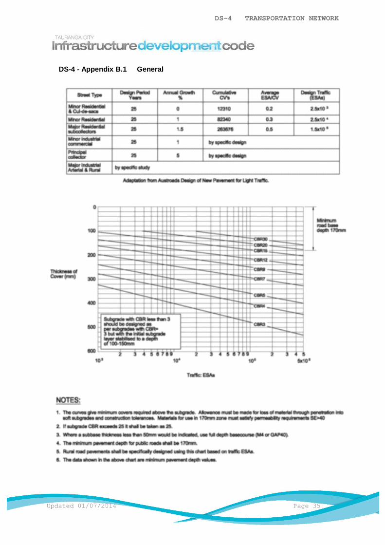
DS-4 TRANSPORTATION NETWORK
Updated 01/07/2014 Page 35
DS-4 - Appendix B.1 General
DS-4 TRANSPORTATION NETWORK
Page 36 Updated 01/07/2014
DS-4 - Appendix CStreet Naming and Sign Standard
DS-4 - Appendix C.1 Application for a Street Name
The Consent Holder shall submit 3 proposed street names for every new streetconstructed that is not currently named (or has a street name allocated to it already), atthe time of Infrastructure Development Works Approval. The size, number and positionof the signs shall also be shown at this time.
The suggested names will be checked against, Tauranga City Council, Western Bay ofPlenty District Council and New Zealand Fire Service records to ensure that streetnames in the region are not similar which can cause confusion for the public andemergency services. Iwi and other interest groups shall also be consulted whereapplicable.
DS-4 - Appendix C.2 Costs of Street Signage
The Consent Holder's Representative shall be responsible for all costs associated withapproval, construction and erection of street name signs.
DS-4 - Appendix C.3 Erection of Street Signs
All street sign installation shall be in accordance with the Manual of Traffic Signs andMarkings (MOTSAM) standards.
DS-4 - Appendix C.4 Street Sign Standards
Where not covered below, standards for street name blades provided by the NewZealand Transport Agency (NZTA) shall apply:
a) Street Name Blades:
i) Blades: 200mm depth.
ii) Font: Transport medium Upper and lower case with no compression.
iii) Height: 117mm Caps using upper and lower case.
iv) Text: VIP (WOA).
v) Background: Blue Electronic Cuttable Film.
vi) Border: None.
vii) Materials: 2.5mm Aluminium.
viii) Shape: Rectangle.
ix) Arrowhead: Chevron pointing in direction of street as practical.

DS-4 TRANSPORTATION NETWORK
Updated 01/07/2014 Page 37
x) Mounting: Attach to existing utility pole if practical. Sign must not protrude overthe kerb or edge of seal. Minimum height to underside of lowest sign shall be3.0m. Use white steel round section with a 300mm³ minimum concrete baseand rod to prevent twisting.
xi) Fixing: Must accommodate abnormal loads from vandalism.
xii) Location: Refer NZTA Roads and Traffic Standards (Guidelines for StreetName Signs) for locations. Some sites will have specific requirements i.e. lineof sight, intersection geometry.
xiii) Intersection: Small urban roundabouts and channelled intersections shall haveStreet Names in the IDS locations (in place of Chevron Boards) with 150mmtext no compression therefore the blade size increases and a white roundedborder and arrowhead.
b) Supplementary Street Name Blades:
A separate supplementary sign similar to specifications to Street Name Blades shall beattached below the Street Name Blade. These signs include No exit, Street numbers,Private etc.
i) Blade: 150mm depth.
ii) Height: 80mm Caps using upper and lower case.
For situations not covered by the above, the Consent Holder's Representative shallconsult Council for guidance and approval.
DS-4 TRANSPORTATION NETWORK
Page 38 Updated 01/07/2014
DS-4 - Appendix DSafety Audits
DS-4 - Appendix D.1 General
Road safety audits or reviews shall be undertaken for all Council transportation relatedprojects. They are also recommended for subdivisional developments but are notmandatory. Where undertaken, a formal road safety audit or informal review may berequired at one or several stages of a project. The stages and levels of review to beundertaken shall be in accordance with Table 1 – Design Requirements for VariousRoad Classifications and need to be considered at the early stages of any project toidentify which stages of audit or review will be required and to budget for them.
DS-4 - Appendix D.2 Road Safety Audit
A road safety audit is an independent review of a project to identify road or traffic safetyconcerns for all road users and to ensure that all measures to eliminate or mitigate theconcerns identified are considered fully.
Road safety audits must:
a) Be carried out by people independent of the Designer, Developer, Contractor andCouncil who have appropriate experience and training.
b) Address only the road safety concerns of a project and be a formally documentedprocess.
A road safety audit is not a design check, peer review or a judgement on the quality of aproject.
DS-4 - Appendix D.3 Road Safety Reviews
Road safety reviews are recommended for smaller scale projects where undertaking aformal road safety audit would be considered onerous. The road safety review shall becarried out by a Council traffic engineer or his delegate.
Road safety reviews involve checking a design or the constructed project against therelevant sections of the checklists provided in Appendix 2 of NZTA document RoadSafety Audit Procedures for Projects which can be found online at the following link:
http://www.nzta.govt.nz/resources/road-safety-audit-procedures/docs/tfm9-appendix-2.doc
DS-4 - Appendix D.4 Road Safety Audit process
Formal road safety audits shall be undertaken in accordance with the NZTA documentRoad Safety Audit Procedures for Projects.
DS-4 TRANSPORTATION NETWORK
Updated 01/07/2014 Page 39
In brief, the procedure is:
a) The Developer and Council jointly select an appropriately qualified and independentsafety audit team.
b) The Designer provides plans and other project information appropriate to the auditstage to the safety audit team. A briefing meeting can be undertaken at this stage formore complex projects to outline design philosophy and decisions and identify anydesign issues.
c) The safety audit team carries out site inspections and desktop analysis of plans andany other information provided.
d) The safety audit team produce a formal report identifying any potential safetyproblems and measures appropriate to the scale of the project that should beconsidered to mitigate the problems. The report will include a "decision trackingform" which will allow responses and decisions on the audit findings to be recorded.
e) The Designer and Developer use the decision tracking form to comment on auditfindings. They can agree or disagree with audit findings and or recommendationsand make alternative proposals if desired
f) Council consider the audit report and Designer / Developer response and decide onwhether any changes to the project are required and what they should be. An exitmeeting can be held at this stage to discuss and agree problems and potentialsolutions
DS-4 - Appendix D.5 Reconciliation of Unresolved Issues
In the event that Council requires a change that is not acceptable to the developer, thetwo parties shall meet to resolve the issues. The safety audit team shall be present atthe meeting to assist in understanding the issues and the scale of any potential safetyrisks.
DESIGN STANDARDDS-5 STORMWATER
TABLE OF CONTENTS
DS-5.1 General ..............................................................................................................1
DS-5.2 Minimum Requirements ......................................................................................1
DS-5.3 Regional Council Requirements .........................................................................1
DS-5.4 Design ................................................................................................................2
DS-5.5 Conveyance - Primary and Secondary Systems .................................................5
DS-5.6 Stormwater Treatment / Detention ....................................................................15
DS-5.7 Stormwater Discharge ......................................................................................19
DS-5.8 Collection .........................................................................................................21
DS-5.9 Further Considerations .....................................................................................27

DS-5 STORMWATER
Updated 01/07/2014 Page 1
DS-5.1 General
Many developments will change the natural existing drainage pattern so stormwater systemsare typically designed and constructed to manage this change and any potential adverseeffects which may include flood damage, erosion, sedimentation, water pollution anddamage to ecosystems.
The primary goals of a stormwater drainage system are to collect, convey and treat surfacerunoff to minimise flood damage and adverse effects on the environment. There are severalways this can be done. Low Impact Design features such as planted swales, rain gardens,larger grass verges and detention ponds can allow groundwater recharge, slow themovement of water and reduce the amount of pollutants in receiving water bodies. Theseareas may also be used to enhance a development, contributing to the wider environmentalquality of an area.
Understanding the impact of site development, such as the extent of site coverage (includingpaved surfaces), is important and options such as narrower carriageways andsemi-permeable paving for on-road parking can help to reduce runoff.
Stormwater systems may also integrate with the natural drainage system and this can helpmitigate environmental effects, as well as enhance amenity and ecological values.
DS-5.2 Minimum Requirements
Designs shall provide for a stormwater management system that:
a) Complies with the operative City Plan and Infrastructure Development Code (IDC).
b) Is designed to acceptable urban design, landscaping and engineering methods.
c) Minimises, isolates or eliminates health and safety hazards during both its constructionand its use.
d) Minimises, isolates or eliminates any adverse ecological and environmental effects.
e) The stormwater management system shall be located in areas that are geotechnicallysuitable for the system proposed.
Note: Where confirmation of this requirement is not clear a certification statement from aCategory 1 Geo-Professional may be required.
DS-5.3 Regional Council Requirements
The discharge of stormwater, the diversion of natural water during construction, thepermanent diversion of natural water as a consequence of development, activities in the bedor on the banks of a natural waterway and damming of waterways generally requireResource Consents from Bay of Plenty Regional Council unless authorised as a permittedactivity in the Regional Water and Land Plan.

DS-5 STORMWATER
Page 2 Updated 01/07/2014
DS-5.3.1 Vesting of Assets and Transferring of Consents
If it is the intention of the developer to transfer any Stormwater Resource Consent fromBay of Plenty Regional Council to Council, a copy of the draft conditions shall beforwarded to Council for comment on receipt by the Consent Holder.
Council will not accept a transfer of a Bay of Plenty Regional Council issued ResourceConsent unless the assets pertaining to that Resource Consent have been constructedin accordance with the Resource Consent conditions and comply with the IDC. Intentionto vest ownership of any asset and/or transfer of any Resource Consent shall bediscussed with Council at an early stage of planning. Council reserves the right not toaccept any asset and/or accept a transfer of any Resource Consent.
DS-5.4 Design
The following shall apply:
a) Unless otherwise approved by Council, the design of the stormwater system shall be inaccordance with the IDC and may be supplemented by the documents noted in DS-5Apx A.1 General.
b) For catchment areas less than 50ha, surface water run-off using the Rational Method willgenerally be accepted. For larger catchments or where significant storage elements e.g.Ponds are incorporated, surface water run-off shall be determined using an appropriatehydrological or hydraulic model.
c) Low Impact Design for stormwater management is the preferred approach whereappropriate. Well-designed and well-maintained systems which replicate the naturalpre-development hydrological regime can not only mitigate adverse environmentaleffects but can also enhance local amenity and ecological values. Low Impact Designmethods typically include swales, ponds, rain gardens, rain tanks, a reduction inimpermeable surfaces, permeable paving, filter strips, green roofs and constructedwetlands. The use of Low Impact Design methods shall be discussed with Council at anearly stage.Detailed design is required at the time of Infrastructure Development Works Approval.Where no Infrastructure Development Works Approval is required, Council approval shallbe obtained at a time required by Council and before construction of the system.
DS-5.4.1 Alternative Design
Refer to DS-1.3 Alternative Design.
DS-5.4.2 Stormwater Management Systems
The following shall apply:
a) The stormwater management system is an overall system that manages thecollection, conveyance, treatment and discharge of stormwater. The overallstormwater management system shall provide a minimum standard of floodprotection for the community and mitigate any adverse environmental effects.

DS-5 STORMWATER
Updated 01/07/2014 Page 3
b) The overall system shall accommodate flows from a 50 year return period stormevent (2% AEP) unless otherwise stated in a comprehensive stormwater dischargeconsent. The post development run off rates shall be no greater than predevelopment run off rates. Ponding areas shall be provided for only on public roadsand public land.
c) Stormwater designs shall consider the system as a whole, ensure the upstreamcatchment is provided for, ensure the downstream receiving network has thecapacity to cater for the design condition and be appropriately engineered to suit thesite-specific requirements. An appropriate mix of solutions comprising Low ImpactDesign and conventional solutions shall be considered as well as short and long termmaintenance responsibilities/requirements and the whole of life cost implications (i.e.cost of construction, maintenance, renewal or replacement). The overall system alsoneeds to provide for a range of storm events.
d) A subset of the overall system is the primary system. The primary system shallaccommodate flows from a 10 year return period storm event (10%AEP). When theprimary system overloads by either blockage, malfunction or rainfall events in excessof the design capacity then the part of the overall system that compliments theprimary system is known as the secondary system.
e) Water Quality considerations are required to control potential for damagingenvironmental effects to our waterways, habour and aquatic life. Water quality shallbe included in design where required by:
i) Bay of Plenty Regional Council Water and Land Plan requirements.
ii) Bay of Plenty Regional Council resource consent conditions.
iii) Council's Comprehensive Catchment Consent Conditions and associatedManagement Plans as approved by Bay of Plenty Regional Council.
The 90% rainfall storm shall be used as this is the maximised point of runoff volumecapture. The 90% rainfall for Tauranga is 33mm for a 2 year / 1 hour storm.
DS-5.4.3 Hydraulic Design
The following shall apply:
a) The hydraulic design of stormwater pipelines shall be based on tables for thehydraulic design of stormwater drains and pipelines or on graphs or otherrepresentation of the same methods based on the Colebrook White or Manning'sFormula.
b) The pipe roughness coefficient Ks used in the design shall be as shown in NZS4404Table 4.2.
DS-5.4.4 Rainfall Intensity
The following shall apply:
a) Designers shall use the Design Rainfall Tables located in DS-5 - Appendix B.1General.
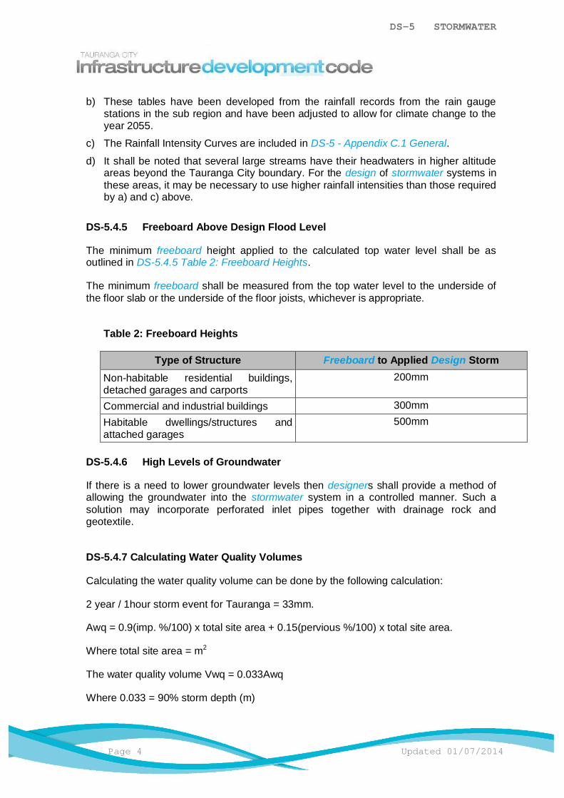
DS-5 STORMWATER
Page 4 Updated 01/07/2014
b) These tables have been developed from the rainfall records from the rain gaugestations in the sub region and have been adjusted to allow for climate change to theyear 2055.
c) The Rainfall Intensity Curves are included in DS-5 - Appendix C.1 General.
d) It shall be noted that several large streams have their headwaters in higher altitudeareas beyond the Tauranga City boundary. For the design of stormwater systems inthese areas, it may be necessary to use higher rainfall intensities than those requiredby a) and c) above.
DS-5.4.5 Freeboard Above Design Flood Level
The minimum freeboard height applied to the calculated top water level shall be asoutlined in DS-5.4.5 Table 2: Freeboard Heights.
The minimum freeboard shall be measured from the top water level to the underside ofthe floor slab or the underside of the floor joists, whichever is appropriate.
Table 2: Freeboard Heights
Type of Structure Freeboard to Applied Design StormNon-habitable residential buildings,detached garages and carports
200mm
Commercial and industrial buildings 300mmHabitable dwellings/structures andattached garages
500mm
DS-5.4.6 High Levels of Groundwater
If there is a need to lower groundwater levels then designers shall provide a method ofallowing the groundwater into the stormwater system in a controlled manner. Such asolution may incorporate perforated inlet pipes together with drainage rock andgeotextile.
DS-5.4.7 Calculating Water Quality Volumes
Calculating the water quality volume can be done by the following calculation:
2 year / 1hour storm event for Tauranga = 33mm.
Awq = 0.9(imp. %/100) x total site area + 0.15(pervious %/100) x total site area.
Where total site area = m2
The water quality volume Vwq = 0.033Awq
Where 0.033 = 90% storm depth (m)
DS-5 STORMWATER
Updated 01/07/2014 Page 5
Examples of this method can be found via case studies provided within the StormwaterManagement Guidelines.
DS-5.5 Conveyance - Primary and Secondary Systems
A primary stormwater system may typically include:
a) Pipe reticulation.
b) Ground soakage systems.
c) Channels and open water courses.
d) Swales and rain gardens.
Mechanical systems such as pumping systems are generally not permitted.
The secondary system comprises a network of overland flowpaths and storage areasdesigned to safely convey and/or store stormwater that exceeds the capacity of the primarysystem.
DS-5.5.1 Selection of a Primary Stormwater System
The type of primary system installed will be dependent on factors such as water quantity,water quality, aquatic resource protection, topography, soil type, location and areaconstraints.
DS-5.5.2 Piped Reticulation
The primary piped reticulation shall be designed to the following minimum requirements:
a) The minimum pipe size other than for connections shall be:
Main receiving property connections only: 200mmØ internal diameterAll other mains and sump leads: 300mmØ internal diameter
b) Manholes are required at each:
i) Intersection of pipes (except for junctions between mains and laterals).
ii) Change of grade.
iii) Change of direction.
iv) Change of pipe size.
v) Change of material (except for repair/maintenance locations).
vi) Permanent or temporary end of a pipe system.
c) Shall provide for the design flow without surcharge.
d) Shall provide for a minimum full bore velocity of 0.6m/s at a flow of half the 50% AEPdesign flow.
e) Where the pipe full velocity is less than 1.3m/s the reticulation design shall allow forsilt collection.

DS-5 STORMWATER
Page 6 Updated 01/07/2014
f) Each branch line (excluding connections) shall join the main line at a manholejunction except for mains ≤50% of the size of the main being connected to may besaddled onto 600mmØ pipes or larger provided that:
i) A manhole is supplied on the branch line within 50m of the saddle.
ii) The saddle is created using a 300mm pipe stub epoxied onto the 600mmØ orlarger main and is inspected prior to laying the first pipe from the stub.
iii) Council approval has been obtained.
g) Pipes shall be designed so that the pipes are laid soffit to soffit. Where this is notpossible or in potentially unstable ground or where special protection is required, thepipeline shall be specifically designed including the choice of materials.
DS-5.5.3 Reticulation Layout
The following shall apply:
a) The alignment of stormwater reticulation shall be laid out to follow the road patternand either:
i) Be located clear of the carriageway.
ii) Be located clear of wheel tracks if within the carriageway.
b) Where a) above is not possible or practical the main may be located:
i) On public land with approval from Council.
ii) Within private property parallel to and located between 1m and 1.5m from thefront, rear and/or side boundaries provided it avoids affecting futuredevelopment options available within the lot.
iii) On the low side of lots that have a cross-fall of more than 1.5m.
DS-5.5.3.1 Close Proximity Rules
T553 T554
The following shall apply:
a) Buildings or structures to be constructed close to a main or lateral/connectionshall comply with the requirements of T553 and T554. Where dispensation hasbeen granted for a building or structure to be built over a main orlateral/connection, foundations shall be designed by a Chartered ProfessionalEngineer.
b) No enclosed building or structure shall be sited over a manhole or closer than500mm from the outside wall of the manhole structure.
c) No building or concrete slab shall be constructed over a connection point to amain.
d) No buildings shall be constructed over a main if there is a connection closerthan 1.0m to the building unless the connection is relocated to the satisfaction ofCouncil.

DS-5 STORMWATER
Updated 01/07/2014 Page 7
e) Encroachment of removable, non-permanent structures e.g. carports, decks,fences may be approved by Council when the structure is designed and builtsuch that it can be dismantled easily in sections. The removal and re-erection ofthese structures shall be at no cost to Council. Council approval is required in allinstances. Council will assess each application on a case by case basis as thevariables at each site will not always be the same e.g. pipe size, trench detailsetc. Council may add a record to the property file of any such approval to ensurethat future property owners are aware of the approval and Council’s right tohave the structure removed at any time for the purposes of maintenance work,emergency work or upgrade work.
DS-5.5.4 Steep Grades
Anti-scour blocks and trench stop configuration shall be detailed on the design drawingsand shall be in accordance with the Standard Drawings. Spacing of anti-scour blocksshall be in accordance with DS-5.5.4. Table 3: Anti-Scour Block Spacing.
Table 3: Anti-Scour Block Spacing
Grade(%)
Requirement Spacing (S)(m)
15–35 Concrete bulkhead S = 100/Grade (%)
>35 Special design Refer to Council
Note: Where scour is a problem on grades flatter than the above, sandbags are often used to stabilise the trench backfill.
Where the natural transfer of water from the trench into thesurrounding ground will not provide sufficient drainage, trenchdrainage shall be provided to divert the water.
DS-5.5.5 Cover Over Pipelines
The following shall apply:
a) In private property:
i) The minimum cover shall be 600mm.
ii) If the cover exceed 3m, specific design and approval is required.
iii) The design of cover shall avoid affecting the future development optionsavailable within the lot.
iv) Where the reticulation lines are located in the front yards of lots, the invertlevel shall be deep enough so as not to interfere with any future drivewayconstruction.
b) In Road Zones:
i) The minimum cover shall be 900mm.

DS-5 STORMWATER
Page 8 Updated 01/07/2014
ii) Sump leads shall achieve 700mm of cover and be a class 4 (Z) rubber ringjointed concrete pipe or equivalent.
c) Where minimum cover cannot be achieved, specific design of pipe and cover isrequired.
DS-5.5.6 Loads on Pipes
The following shall apply:
a) All pipelines shall be designed to withstand all the likely loads to which they will besubject to.
b) In the first instance, load parameters shall be designed to support an 8.2 tonnedesign axle load. Following this:
i) AS/NZS 3725 and AS2566 shall be used as design guides as applicable.
ii) Any loads relating to backfill techniques, construction traffic, temporarystorage of materials and the like shall be incorporated into design parametersand construction methodology.
DS-5.5.7 Concrete Capping of Pipelines
Where minimum cover cannot be achieved, concrete capping may be used taking intoaccount pipe protection and road integrity requirements. Approval from Council isrequired for the use of concrete capping.
DS-5.5.8 Pipe Materials
Refer to AM-5 Stormwater.
DS-5.5.9 Pipe Joints
All pipelines shall be fully sealed by use of rubber joint rings or welding as appropriateunless otherwise approved by Council.
DS-5.5.10 Pipe Bedding and Backfill
T551
The following shall apply:
a) Pipe bedding and backfill shall be specifically designed, shown on the detaileddesign drawings and submitted to Council for approval.
b) The design shall also include the compaction criteria to be used to certify the backfillhas been compacted to the required compaction standard.
c) All trench backfill under carriageways shall be designed and constructed to achievefor the required pavement layers strengths for the class of road it is beneath.
DS-5 STORMWATER
Updated 01/07/2014 Page 9
DS-5.5.11 Piped Reticulation Structures
This section describes the requirements for structures that may be present in conveyingstormwater through a reticulated system. Theses are categorised as:
a) Manholes.
b) Rodding Eyes.
c) Alternative structures as specifically designed.
The selection of a suitable location for these structures may influence the pipealignment. Generally a minimum clearance of 1.0m shall be provided clear of theopening around any structure that may allow entry for maintenance and rescueequipment. Council may determine other specific requirements subject to the individualsite characteristics.
DS-5.5.11.1 Manholes
T501, T502, T503, T504, T505, T506, T507
The following shall apply:
a) Manhole spacings shall not exceed 100m for pipe lines up to 900mmØ withoutspecific approval from Council. Greater spacing may be approved for largerdiameter pipes.
b) The entire manhole structure shall be located clear of all boundaries.
c) Manholes shall be located within Council property or Road Zones whereverpossible.
d) Manholes deeper than 5.0m to the pipe invert and shallow manholes may beused in certain circumstances subject to the approval of Council. Where amanhole is more than 5.0m deep it shall:
i) Be specifically designed.
ii) Have access steps installed.
iii) Incorporate clear warning that it is deep.
iv) Have a secure entrance.
v) Require larger diameter chambers and covers.
e) Standard 1050mmØ manhole risers are not suitable where the pipes are eitherlarger than 675mmØ or where multiple pipes enter a manhole causing loss ofthe manhole wall. Manholes shall be designed to maintain wall integrity inthese circumstances.
f) Manholes shall not be located within the road carriageway unless approved bythe Council. Where approved for installation within the road carriageway theyshall be located clear of vehicle wheel tracks.
g) All manholes shall have an entry safety grill fitted.
h) All standard manholes shall be constructed as detailed on the StandardDrawings.

DS-5 STORMWATER
Page 10 Updated 01/07/2014
DS-5.5.11.2 Manhole Sizing
The following shall apply:
a) The standard internal diameter of circular manholes shall be 1050mmØ. Othernominal internal diameters that may be used for larger pipe sizes or situationsare 1200mmØ, 1500mmØ and 1800mmØ.
b) When considering the appropriate manhole diameter consideration shall begiven by the designer to the base layout to ensure hydraulic efficiency andadequate working space in the chamber.
c) Where there are several inlets, consultation with Council on the layout of thechamber is recommended.
DS-5.5.11.3 Benching
The following shall apply:
a) Benching shall be provided in the base of each manhole that provides a safeplace to stand for maintenance purposes.
b) Benching shall be close to flat with a cross fall (6H:1V) into the manhole pipesystem for drainage purposes.
c) Channels shall have a minimum inside radius of 300mm.
DS-5.5.11.4 Internal Falls Through Manholes
The fall through a manhole shall be the greater of either of the following:
a) The invert of the outlet pipe from a manhole shall be 20mm lower plus 0.5mmper degree of horizontal angle change between the two lines lower than thelowest incoming pipeline invert.
b) The soffit of the outlet pipe shall be level with or below the soffit of the lowestincoming pipeline.
c) The extension of the grade of the steepest pipe across the width of the manhole.
DS-5.5.11.5 Flotation
In areas of high water table all manholes shall be designed to provide a factor ofsafety against flotation of 1.25.
DS-5.5.11.6 Access Steps
T503
Manhole steps shall comply with the Standard Drawings and AM-5 Stormwater.Stormwater manhole steps shall not be located above any inlet or outlet pipes.
DS-5 STORMWATER
Updated 01/07/2014 Page 11
DS-5.5.11.7 Covers
T504, T505, T506, T507
The following shall apply:
a) Manhole covers with a minimum clear opening of 600mm in diameter shall beused.
b) Non-Rock covers shall be used on all Level 2 (or primary arterial) roads.
c) Refer to AM-5 Stormwater for manhole cover type.
d) All covers shall be painted with New Zealand Transport Agency (NZTA)Standard approved "blue" road marking paint.
DS-5.5.12 Rodding Eyes
T520, T521
The following shall apply:
a) A rodding eye is required to be constructed at the ends of some lateral pipes that areinstalled between a property connection point and the stormwater main.
b) PVC-U bends up to 45° are acceptable.
c) A standard manhole frame and cover shall be installed over the entry point when notlocated in a hardstand area. A fire hydrant base and rodding eye cover shall be usedin hardstand areas.
d) All covers must be painted with New Zealand Transport Agency (NZTA) Standardapproved "blue" road marking paint.
e) All standard rodding eyes shall be constructed as detailed on the StandardDrawings.
DS-5.5.13 Ground Soakage Systems
Refer to DS-5.7.2 Ground Soakage Discharge.
DS-5.5.14 Channels and Open Watercourses
Where natural open stream systems or formed channels are to be incorporated in thestormwater drainage system they shall generally be located within a drainage reserve ofsufficient width to contain the overall system design storm flow. The following shall apply:
a) It must be demonstrated that the open drain system:
i) Can be used where it is in keeping with the existing drainage network.
ii) Provides adequate capacity.
iii) Has a maximum velocity in an unlined open drain of 0.5m/sec where ash orclay soils are present. Where this can not occur, an appropriate channel liningwill be required.

DS-5 STORMWATER
Page 12 Updated 01/07/2014
b) Drainage reserves shall have maximum and minimum slopes of 1:5 and 1:50respectively and when access for maintenance is required, shall also include:
i) A 4m wide access that is accessible by a 8.2 tonne axle weight vehicle for itsentire length as per NZ On-Road Tracking Curves RTS 18.
ii) Access from public carriageways.
c) To encourage the best use of the open stream systems the drainage reserve shall,where possible, be linked with other reserves and open spaces to accommodate offroad pedestrian and cycle access. Access points for public use and maintenanceshall be provided at regular intervals along the system together with footpath andpedestrian bridges as may be defined in the Resource Consent.
d) The flow characteristics of natural open stream systems shall:
i) Be based on the likely long term stream condition in terms of density ofvegetation.
ii) Be cleared of all unsuitable plant growth and replanted to a landscape designapproved by Council.
iii) Take account of the possibility of blockage under all peak flood conditions.
iv) Include protection of the low flow channel against scour and erosion of thestream bed where necessary.
v) Not be adversely affected by the discharge of stormwater resulting fromdevelopment or a new discharge to the stream.
vi) Be designed to avoid erosion of the stream banks.
e) Catchment or detention factors that may lead to an increase in the temperature ofthe stormwater (e.g. large sealed areas) shall be mitigated.
DS-5.5.15 Vegetated Swales
Vegetated swales are stormwater channels that are often located alongside roads or inreserves. While their primary function is conveyance, filtration through the vegetation canreduce peak flows and provide water quality treatment. They can be used in place ofkerbs, gutters or piped networks to treat and transport stormwater runoff and can beaesthetically pleasing and contribute to the overall urban design of an area.
Types of swale include:
a) Dry Swale (including an underdrain) – generally grassed
b) Infiltration Swale (No underdrain) – generally grassed
c) Bioretention Swale (Planted with low lying native wetland plants and permanentlywet)
The type of swale chosen depends on physical site conditions and quality treatmentrequirements.
DS-5.5.15.1 Minimum Requirements
It must be demonstrated that a swale system complies with the following:

DS-5 STORMWATER
Updated 01/07/2014 Page 13
a) A maximum catchment area not greater than 4 hectares.
b) Appropriate functionality and adequate capacity.
c) Capacity for a 10% AEP storm event.
d) A longitudinal slope of between 1 and 5%. For longitudinal slopes that aregreater than 5% or where velocity is greater than 1.5m/s in a 10% AEP stormevent, erosion protection or check dams to reduce effective gradient may berequired.
e) Minimum hydraulic residence time of 9 minutes.
f) Maximum side slope of 5H:1V for maintenance access.
g) Level spreaders shall be provided where piped flows enter the swale in order forflows to be dispersed.
h) Planted with grass or other low lying plants in a permeable soil with the purposeof reducing flow velocities and protecting against erosion. Grass shall have adesign vegetation height between 50-150mm. A planting plan shall be submittedto Council for approval.
i) Achieves all other relevant performance standards for the primary system
The designer shall refer to Councils Stormwater Management Guidelines for moreinformation regarding designs of this type.
DS-5.5.16 Vegetated filter Strips
Vegetated Filter Strips are used to manage stormwater runoff from impervious surfacesby slowing runoff velocities, providing treatment and promoting infiltration. They often actas pre-treatment for other stormwater devices or receiving systems.
Vegetated Filter Strips receive stormwater runoff as sheet flow whereas swales acceptmore concentrated flow. Filter strip performance relies on even distribution of flowacross vegetated areas as well as residence time.
DS-5.5.16.1 Minimum Requirements
It must be demonstrated that a filter strip system complies with the following:
a) A maximum catchment area not greater than 2 hectares.
b) Appropriate functionality and adequate capacity.c) Capacity for a 10% AEP storm event.
d) A slope less than 5% unless terracing or level spreaders are provided mid slope.
e) Minimum hydraulic residence time of 9 minutes.
f) Velocity no greater than 1.5 m/s in a 10% AEP storm event unless erosionprotection is provided.
g) Grass shall have a design vegetation height 50-150mm.
h) Achieves all other relevant performance standards for the primary system.
DS-5 STORMWATER
Page 14 Updated 01/07/2014
The designer shall refer to Councils Stormwater Management Guidelines for moreinformation regarding designs of this type.
DS-5.5.17 Rain Gardens
Rain Gardens are engineered bioretention systems designed to use the natural ability offlora and fauna to reduce stormwater volumes, peak flows and contaminant loads. Theycan be designed for either infiltration to groundwater or discharge to the downstreamnetwork. Rain Gardens can be used in place of conventional landscape areas andcontribute an attractive urban design feature as well as having an ecological value.
DS-5.5.17.1 Minimum Requirements
It must be demonstrated that a Rain Garden complies with the following:
a) Capacity for a 10% AEP storm event without significant scour or erosion.
b) Appropriate functionality and adequate capacity.
c) Size is calculated to achieve water quality volume.
d) Entry and overflow positions to restrict short circuiting.
e) Appropriately planted (for wet and dry conditions) with native plant species(preferred) and incorporating a mulch, pebble or rock surface layer. A plantingplan shall be submitted to Council for approval.
f) Ponding area with a maximum ponded water depth of 300mm.
g) An overflow bypass system shall be provided for when the Rain Garden pond isfull.
h) Filtration layers shall comprise of the following:
i) Filtration soil media layer: 400-600mm deep.
j) Transition coarse sand layer: 100mm deep.
k) Final drainage layer of 2-5mm washed gravel: 50mm deep (minimum).
l) Filtration soil media shall be sandy loam or loamy sand, free of rubbish, plantsand weeds.
m) An underdrain shall be provided if piping to the downstream network. This shallhave a minimum 50mm gravel cover.
n) Includes geotextile on the side walls.
o) Achieves all other relevant performance standards for the primary system.
p) Provides access for maintenance.
q) Where Rain Gardens are to be provided on individual lots, covenants on eachlot title are to be created to require owners to maintain the Rain Gardens. Anoperation and maintenance plan shall be submitted to Council for approval.
The designer shall refer to Councils Stormwater Management Guidelines for moreinformation regarding designs of this type.
DS-5 STORMWATER
Updated 01/07/2014 Page 15
DS-5.5.18 Other Alternative Design Methods
Refer to DS-1.3 Alternative Design.
DS-5.5.19 Secondary System
No buildings or structures shall be located within secondary overland flow paths.
DS-5.5.19.1 Secondary System Options
Secondary system options may include:
a) Preferred Options:
i) Temporary ponding on local and collector roads.
ii) Temporary flow along local and collector roads.
iii) Temporary flow on public land such as accessways, parks and reserves.
b) Least Preferred Options:
i) Flow across private land (the least desirable option). Such flows must bein a defined channel or swale, clear of existing or future building sites andprotected by an easement in favour of Council as well as a ResourceConsent notice which prohibits ground reshaping and the erection of anybarriers to the secondary flows.
ii) Stormwater pumping systems are not permitted.
iii) Piped secondary systems are not permitted.
DS-5.6 Stormwater Treatment / Detention
Stormwater ponds are an accepted method of improving stormwater quality, reducingdownstream flood potential and peak downstream flow rates. Council is not in favour ofencouraging a proliferation of small stormwater ponds but prefers a totalcatchment/treatment train approach.
DS-5.6.1 Permanent Pond Type
Council accepts the use of dry and wet ponds as a part of an engineered solution and/ortreatment train. However, the selection and design criteria (short term as well as longterm functionality, maintenance, ownership) must be approved by Council beforeconstruction. Access from public carriageways shall be provided for maintenance.
DS-5.6.1.1 Regional Council Resource Consent
The following shall apply:
DS-5 STORMWATER
Page 16 Updated 01/07/2014
a) Permanent ponds may require Resource Consent from Bay of Plenty RegionalCouncil as part of an earthworks and/or stormwater discharge ResourceConsent. Refer to DS-5.3 Regional Council Requirements and contact Bay ofPlenty Regional Council for more information.
b) Temporary ponds may require Resource Consent from Bay of Plenty RegionalCouncil as part of the earthworks Consent and/or discharge Resource Consent.Refer to DS-5.3 Regional Council Requirements and contact Bay of PlentyRegional Council for more information.
c) Pollutants and contamination issues shall be identified and managed to thesatisfaction of Council and any Resource Consent conditions related to thepond.
DS-5.6.1.2 Permanent Pond Ownership and Location
a) If acceptance of ownership of a pond is agreed by Council all stormwater pondsshall be located on land either:
i) Owned by Council.
ii) Proposed to be vested in Council at completion of the development.
iii) Covered by appropriate easements approved by Council relating toaccess, serviceability, storage and replacement or repair of the pond.
b) Ponds that are not proposed to be vested in Council shall be discussed withCouncil prior to application for Resource Consent or, if no Resource Consent isrequired, prior to construction of the pond to ensure the pond construction hasminimal or no impact on Council’s existing stormwater system.
DS-5.6.1.3 Detention Pond Design
The following shall apply:
a) Detention Ponds shall be designed to the following minimum requirements:
i) Compliance with DS-1 - Apx A.1 General.
ii) Stormwater ponds shall be designed to ensure that retention andtreatment to achieves removal of 75% of total suspended sediment smallerthan 120µm diameter on a long term average basis.
iii) Any pond shall be designed to ensure any discharge has a suspendedsolids concentration no higher than 150 g/m³.
b) Specific matters to consider in pond design:
i) Side slopes with safety considerations - maximum 1:5 slope above andbelow water level.
ii) Ease of access for and of maintenance including mowing and silt removaland disposal and access to public roads.
iii) Shape and contour for amenity value.
iv) Effectiveness of inlet and outlet structure/s.
v) Overflow design and scour protection.
vi) Pest control (rats, mosquitoes etc.) and wind blown debris.
DS-5 STORMWATER
Updated 01/07/2014 Page 17
vii) Sustainability of aquatic life.
viii) Depth of water.
ix) Use in treatment of stormwater.
x) Minimise dead zones and short-circuiting to improve the treatmentperformance of the pond.
Note: Dependent on catchment water quality, local ground conditions and soil properties,Council may require, (in exceptional cases), that ponds shall be lined.
The designer shall refer to Councils Stormwater Management Guidelines for moreinformation regarding designs of this type.
DS-5.6.1.4 Pond Location
The following shall apply:
a) If acceptance of ownership of a pond is agreed by Council all stormwater pondsshall be located on land either:
i) Owned by Council.
ii) Proposed to be vested in Council at completion of the development.
iii) Covered by appropriate easements approved by Council relating toaccess, serviceability, storage and replacement or repair of the pond.
b) Ponds that are not proposed to be vested in Council shall be discussed withCouncil prior to application for Resource Consent or, if no Resource Consent isrequired, prior to construction of the pond to ensure the pond construction hasminimal or no impact on Council's existing stormwater management network.
DS-5.6.2 Constructed Wetlands
Constructed wetlands are large shallow planted ponds which are designed to providestormwater quality improvement, reduce downstream flood potential and peakdownstream flow.
They differ from Detention Ponds in that they can be shallower, provide greatercontaminant removal (including nutrients) and support a wider variety of aquatic plantsand wildlife. They can also be more attractive and designed to provide greater amenity,ecological and safety benefits.
It must be demonstrated that a constructed wetland complies with the following:
a) A catchment area greater than 1 hectare.
b) Size is calculated to achieve water quality volume.
c) Includes a littoral and main wetland area at a depth not exceeding 1.0m.
d) Shall be appropriately planted.
e) Includes inlet pipework with appropriate erosion control.
f) Includes an emergency overflow.
DS-5 STORMWATER
Page 18 Updated 01/07/2014
g) Designed for a controlled discharge rate that allows for continuous flow through awetland to prevent stagnation.
h) Provides access for maintenance.
Council approval shall be obtained prior to design and construction of any wetland. AllResource Consent, location, functionality, maintenance and ownership issues shall beconfirmed prior to any detailed design commencing.
The designer shall refer to Councils Stormwater Management Guidelines for moreinformation regarding designs of this type.
DS-5.6.3 Permeable Pavements
Permeable Pavements are hard surface paving systems that reduce stormwater runoffflows and improve runoff water quality. Their porous surface allows stormwater to soakthrough them before slowly draining away.
The 3 main types that exist are:
a) Open cell grid of concrete or plastic with sand/gravel or grass cover.
b) Solid interlocking blocks with drainage gaps.
c) Porous interlocking blocks.Permeable Pavements shall only be used in low traffic areas such as carparks,driveways and footpaths.
Council approval shall be obtained prior to design and construction of PermeablePavement.
The designer shall refer to Council's Stormwater Management Guidelines for moreinformation regarding designs of this type.
DS-5.6.4 Bio-Retention Tree Pits
Bio-Retention Tree Pits collect stormwater from small car park areas or roads. They canreduce stormwater runoff flow velocity, improve runoff water quality and contribute to theoverall urban design and aesthetics of an area.
It must be demonstrated that a Tree Pit complies with the following:
a) Appropriate functionality and adequate capacity.
b) Has a ponding area at a level which sits below surrounding land and a maximumponded water depth of 300mm deep.
c) Filtration layers shall comprise of the following:
i) Filtration soil media layer: 400-600mm deep.
ii) Final drainage layer of 2-5mm washed gravel: 300mm deep.
d) Filtration soil media shall be sandy loam or loamy sand, free of rubbish, plants andweeds with a minimum permeability of 0.3m/day.

DS-5 STORMWATER
Updated 01/07/2014 Page 19
e) Ponding area should drain completely within 24 hours.
f) An underdrain shall be provided in the final drainage layer with a minimum cover of50mm.
g) An overflow bypass system shall be provided which sits below the surroundingground surface.
h) Achieves all other relevant performance standards for the primary system.
i) Provides access for maintenance.Council approval shall be obtained prior to construction of Bio-Retention Tree Pits.
The designer shall refer to Councils Stormwater Management Guidelines for moreinformation regarding designs of this type.
DS-5.7 Stormwater Discharge
This section describes the requirements for structures or methods for discharge ofstormwater runoff. These are categorised as:
a) Discharge structures.
b) Ground soakage discharge.
c) Open watercourses.
d) Public roadside kerb and channel connection.
e) Road or bubble-up sumps.
f) Discharge Quality.
The selection of a suitable location for these structures may influence the pipe alignment.Generally a minimum clearance of 1.0m shall be provided clear of the opening around anystructure that may allow entry for maintenance and rescue equipment. Council maydetermine other specific requirements subject to individual site characteristics.
DS-5.7.1 Discharge Structures
The following shall apply:
a) Discharge structures shall be installed at the outlets of pipelines to the detail shownon Standard Drawings.
b) There shall be a single point of discharge from any one structure.
c) Shall be designed to minimise the effect of erosion on the receiving environment andinclude an energy dissipation device where required. (Submitted designs mustclearly illustrate this requirement).
d) No grill shall be constructed on outlet structures. A hazard warning sign shall beplaced on all outlet structures 500mmØ or larger as defined on the StandardDrawings.
e) Where a pipe is to be installed in a swale or open drain to allow for access over thedrain, an outlet structure may be required to be installed to prevent erosion aroundthe pipe exit.

DS-5 STORMWATER
Page 20 Updated 01/07/2014
DS-5.7.2 Ground Soakage Discharge
Disposal of stormwater by ground soakage or ground water recharge is only suitable insome areas of Tauranga (i.e. parts not located near relic slips or plateau edges) andmost areas of the Mount Maunganui and Papamoa portions of Tauranga City. Thefollowing applies to ground water soakage methods:
a) Concept approval is required from Council before undertaking detailed design for anyuse of Ground Soakage. The detailed design is then subject to InfrastructureDevelopment Plan Approval.
b) Where no Development Works Approval is required as part of a Resource Consent,then Council approval shall be obtained at either application for Resource Consent oranother time specified by Council and before construction of the system
c) All soakage systems shall be specifically designed to meet the performance criteriarequired by the New Zealand Building Code Handbook and Approved Documentssection E1 - Surface Water and include the design parameters outlined in thissection of the IDC.
d) Testing determines that the soil, geotechnical and groundwater characteristics aresuitable.
e) The rate of soakage is determined by an assessment conducted by an appropriatelyqualified and experienced Chartered Professional Engineer. (In some cases aCategory 1 or 2 Geo-Professional will be required.
f) A soakage rate reduction factor of 0.5 is applied to ensure that the system isdesigned for what can be expected in its operating environment.
g) Confirmation that use of the soakage system will not have an adverse effect on otherland, property and structures including land stability, seepage or overland flowperspectives. i.e. that adjoining slopes, basements, retained and unretained battersare identified and the possible effects on these features quantified.
h) Confirmation of the expected overland flowpath/s where the soakage systemoverflows and how this will be managed.
i) Confirmation that the specifically designed soakage system can service the"maximum potential impermeable area" of the site to cater for future development.
j) It includes areas clear of a flood event up to the 50 year return period storm event(2%AEP).
k) The system contains the volume of storage required where the rate of inflow exceedsthe rate of soakage for the design storm.
l) The method of storage is approved.
m) Details of how the soakage system will be constructed, accessed and what the longterm maintenance regime for the system is.
n) All stormwater entering the storage/soakage portion of the system enters does so viaa silt entrapment device to ensure the long term serviceability of the system.
o) Soakholes, soakpits or entry points shall be located to allow for adequate and safeaccess for maintenance.
p) Each soakhole, soakpit or entry point pit shall be fitted with a removable lid for easeof access and maintenance.

DS-5 STORMWATER
Updated 01/07/2014 Page 21
q) Location of soakholes, soakpits or entry points shall be submitted for Council recordsbefore issue of building Code of Compliance certificates.
r) Stormwater entry to soakholes, soakpits or other soakage mechanism from externalhardstand areas shall be through a yard sump (as shown on the Standard Drawings)or other such similar structure so minimal sediment enters the soakage environment,ensuring the long term serviceability of the system.
s) The entire soakhole, soakpit or soakage mechanism shall be located above the staticgroundwater level in heavy rain conditions.
t) Areas of soakage suitability, specific design and soakhole decommissioning areasare displayed in Council’s GIS system. This is available for viewing at the CustomerService Centre at the main Council offices. Also refer to DS-5 - Apx D – Appendix D:Disposal of Stormwater by Ground Soakage.
DS-5.7.3 Open Watercourse
This is generally permitted but only where an existing open public watercourse isavailable. This method may require a Resource Consent for discharge from Bay ofPlenty Regional Council.
DS-5.7.4 Public Roadside Kerb and Channel Connection
T535
Kerb connections can be made only to vertical kerb and channel and service 1independent dwelling unit per connection. This option will be approved by Council onlyproviding the kerb connection can be shown not to cause or increase flooding in thedownstream catchment for the street and no other reasonable options are available.
DS-5.7.5 Road or Bubble-up Sumps
T425, T426, T427, T525
This option is not a preferred solution. A connection to a road sump or construction of abubble up sump shall occur only with approval from Council. Subsoil drainagereticulating groundwater seepage or under channel drains may be connected to roadsumps.
DS-5.7.6 Discharge Quality
If the discharge is a permitted activity the quality shall meet the discharge standard asspecified in the Bay of Plenty Regional Council Regional Water & Land Plan.
DS-5.8 Collection
This section describes the requirements for structures or methods for collection ofstormwater run off. These are categorised as:

DS-5 STORMWATER
Page 22 Updated 01/07/2014
a) Inlet structures (e.g. wingwalls).
b) Sumps.
c) Property service connections.
d) Alternative collection methods.
The selection of a suitable location for these structures may influence the pipe alignment.Generally a minimum clearance of 1.0m shall be provided clear of the opening around anystructure that may allow entry for maintenance and rescue equipment. Council maydetermine other specific requirements subject to individual site characteristics.
DS-5.8.1 Inlet Structures
T523, T524
The following shall apply:
a) Inlet structures (such as wingwalls) shall be provided at the inlets of pipelines to thedetail shown on Standard Drawings.
b) A grill shall be installed on all inlet structures of 500mmØ or larger. This grate shallbe specifically designed and submitted to Council for approval.
c) Where the consequences of a grating blockage are likely to be severe, a backupoverflow system that allows runoff to enter the pipe or a clearly defined secondaryflowpath shall be provided.
d) Where a pipe is to be installed in a swale or open drain to allow for access over thedrain, an inlet structure may be required to prevent erosion around the pipe entry.
DS-5.8.2 Sumps
T425, T426, T427, T525
The following shall apply:
a) Yard sumps shall be provided as a means of capturing run-off from private land,swales and any other grassed areas where applicable. These shall be constructedas per the Standard Drawings.
b) For road and right-of-way sumps refer to DS-4 Transportation Network.
DS-5.8.3 Property Service Connections
The point of connection is the junction between a property’s private drain and the publicstormwater network. Private drainage generally extends through to the propertyboundary at which point Council accepts responsibility for the downstream pipelines.
DS-5.8.4 Minimum Requirements
Property service connections shall be designed to the following minimum requirements:

DS-5 STORMWATER
Updated 01/07/2014 Page 23
a) Each lot shall have one service connection (except where internal ground soakage isprovided and appropriate).
b) All lots shall be connected to a piped reticulation system or a specifically designedstormwater mechanism (including soakage devices if appropriate).
c) Specific Council approval is required to connect to the following:
i) An open drain.
ii) A public roadside kerb & channel connection.iii) A road or bubble up sump.
d) Any individual lot/property connection shall be designed and located to suit theexisting and future development scenarios and where possible sized, located anddesigned to service the whole property (land parcel), but as a minimum, to servicethe building platform and impermeable area.
e) Any connections shall be located to service the lowest practical building platform onthe property.
f) The design shall specify the requirements for the property connections including planlocation, lot contours and invert level at property boundary or junction with the mainas applicable.
DS-5.8.5 Private Drainage
Generally all stormwater pipes installed between a building and the point of connectionto Council’s stormwater network are private assets. The Building Act requires that aBuilding Consent shall be obtained for their installation or alteration and that this workmust be carried out only by a registered drainlayer.
The following shall apply:
a) Further approval must also be obtained from Council before these drains may beconnected to the stormwater network. Application for this shall be on Council's WaterSupply / Drainage / Vehicle Crossing Connection Application Form.
b) All connections to Council infrastructure can be carried out only by a CouncilLicensed Contractor.
DS-5.8.6 Connection Locations
Connections shall be:
a) Clear of obstructions, e.g. tree, tree roots, paved areas.
b) Easily accessible for future maintenance.
c) Clear of any known future developments e.g. swimming pools or driveways.
DS-5.8.7 Connection Depth
T530, T531
The following shall apply:

DS-5 STORMWATER
Page 24 Updated 01/07/2014
a) Connection depths shall be set to drain the whole serviced area recognising thefollowing factors:
i) Any connection points shall have a minimum cover of 600mm and be nodeeper than 1.5m. (Deeper connections may be installed in somecircumstances but only with the prior approval of Council).
ii) Surface level at plumbing fixtures of buildings (existing or proposed).
iii) Depth to the invert of pipe at plumbing fixture or intermediate points.
iv) Invert of the public main at junction point.
v) Allowance for crossing other services.
vi) Allowance for minimum gradients of laterals and private drainage.
vii) Lateral junctions installed at minimum of 45° (vertical) to main.
b) The designed invert level at the connection shall be no higher than the lowestcalculated level consistent with these factors.
DS-5.8.8 Installation of Connections
T530, T531, T532, T533, T534, T535, T536
The following shall apply:
a) The end of each connection pipe shall be sealed with a solvent welded cap paintedblue if the connection does not occur immediately.
b) Where the inspection is to a property servicing multiple residential units then asurface accessible inspection chamber such as a manhole, rodding eye or otherCouncil approved structure shall be installed.
c) Each connection point shall be marked with a 50mm x 50mm timber stake paintedblue which shall extend from the invert to a minimum of 300mm above finishedground level. A blue PVC marker tape shall be attached to the connection pipe,brought up and tied to the top of the stake.
d) Where larger sized capping is required or a factory supplied cap is not available,specific design of these shall be required for approval.
DS-5.8.9 Connection Destinations
Where practicable and where connection is to be within 5m of a manhole, the connectionshall be to the manhole.
DS-5.8.10 Lateral Configurations
T537, T538, T539, T540, T541,T542
To provide a service connection to each lot, a minimum 100mmØ line shall be extendedfrom the main reticulation system to terminate within the property boundary at aminimum distance of 1.0m from the front and side boundaries whether created bycross-lease, unit title or fee-simple subdivision.
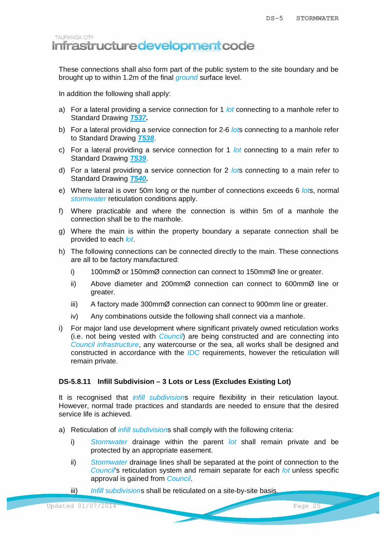
DS-5 STORMWATER
Updated 01/07/2014 Page 25
These connections shall also form part of the public system to the site boundary and bebrought up to within 1.2m of the final ground surface level.
In addition the following shall apply:
a) For a lateral providing a service connection for 1 lot connecting to a manhole refer toStandard Drawing T537.
b) For a lateral providing a service connection for 2-6 lots connecting to a manhole referto Standard Drawing T538.
c) For a lateral providing a service connection for 1 lot connecting to a main refer toStandard Drawing T539.
d) For a lateral providing a service connection for 2 lots connecting to a main refer toStandard Drawing T540.
e) Where lateral is over 50m long or the number of connections exceeds 6 lots, normalstormwater reticulation conditions apply.
f) Where practicable and where the connection is within 5m of a manhole theconnection shall be to the manhole.
g) Where the main is within the property boundary a separate connection shall beprovided to each lot.
h) The following connections can be connected directly to the main. These connectionsare all to be factory manufactured:
i) 100mmØ or 150mmØ connection can connect to 150mmØ line or greater.
ii) Above diameter and 200mmØ connection can connect to 600mmØ line orgreater.
iii) A factory made 300mmØ connection can connect to 900mm line or greater.
iv) Any combinations outside the following shall connect via a manhole.
i) For major land use development where significant privately owned reticulation works(i.e. not being vested with Council) are being constructed and are connecting intoCouncil infrastructure, any watercourse or the sea, all works shall be designed andconstructed in accordance with the IDC requirements, however the reticulation willremain private.
DS-5.8.11 Infill Subdivision – 3 Lots or Less (Excludes Existing Lot)
It is recognised that infill subdivisions require flexibility in their reticulation layout.However, normal trade practices and standards are needed to ensure that the desiredservice life is achieved.
a) Reticulation of infill subdivisions shall comply with the following criteria:
i) Stormwater drainage within the parent lot shall remain private and beprotected by an appropriate easement.
ii) Stormwater drainage lines shall be separated at the point of connection to theCouncil’s reticulation system and remain separate for each lot unless specificapproval is gained from Council.
iii) Infill subdivisions shall be reticulated on a site-by-site basis.

DS-5 STORMWATER
Page 26 Updated 01/07/2014
iv) For minor infill subdivision type works, all private Stormwater works shall beconstructed in accordance with the NZ Building Code regulations.
b) Infill subdivisions shall be reticulated on a site by site basis to the approval ofCouncil.
c) Lateral connections shall be constructed or upgraded in accordance with the IDC.This lateral can be vested in Council and provide each lot with the same standard ofindividual connection as new ‘greenfields’ lots.
d) Where this is considered impractical or unnecessary, the Consent Holder may makeapplication to Council for the lateral to remain private within an appropriateeasement. However common private reticulation is not encouraged so as toalleviate the friction that sometimes occurs between neighbours when sharedservices are involved.
e) Lateral connections shall be separated at the point of connection to Council’sreticulation system and remain separate for each lot unless specific approval isgranted by Council. Where the main is within a neighbour's property, the newjunction may be installed immediately within the property being subdivided.
DS-5.8.12 Multi-Unit Properties (Such as Apartment Buildings and BodyCorporate Developments)
For multiple occupancies (unit title, cross lease or company lease) service of the wholeproperty shall be achieved by providing a single point of connection to the stormwatersystem. Connection of the individual units is by joint service pipes owned and maintainedby the body corporate, tenants in common or the company as the case may be. In thisinstance the whole of the multiple occupancy shall be regarded as a single lot. Alldrainage within the development boundary would be private.
Alternatively, if authorised by Council, developers may have the option of providingdrainage facilities to individual titles or tenements in new developments by extending thepublic line into the lot and providing a separate lateral/connection to each unit. In suchcases all internal drainage shall be in accordance with the IDC. Easements shall becreated at Council's discretion and to Council standards.
DS-5.8.13 Commercial and Industrial Connections
The following shall apply:
a) All commercial and industrial lots shall be provided with a stormwater connection.
b) The connection and accepting reticulation mains shall be sized to cater for themaximum potential impermeable area of the site. All paved areas shall be reticulatedfor piped stormwater disposal.
c) Pollutants and contamination issues shall be identified and managed to thesatisfaction of Council though the Building Consent Process.

DS-5 STORMWATER
Updated 01/07/2014 Page 27
DS-5.8.14 Connection to Existing Council Reticulation
Approval shall be obtained from Council before connection can be made to thestormwater network. Application for this shall be on Council's Water Supply / Drainage /Vehicle Crossing Connection Application Form.
All connections to Council infrastructure shall be carried out only by a Council LicensedContractor.
DS-5.9 Further Considerations
The following shall also be considered as part of the design process:
a) DS-5.9.1 Trenchless Technology.
b) DS-5.9.2 Access Requirement.
c) DS-5.9.3 Fencing.d) DS-5.9.4 Easements.
e) DS-5.9.5 Rural and Rural-Residential Zones.
DS-5.9.1 Trenchless Technology
Trenchless technology may be preferred or required for alignments passing through orunder:
a) Environmentally sensitive areas.
b) Built-up or congested areas to minimise disruption and reinstatement.
c) Railway and major road crossings.
d) Significant vegetation.
e) Vehicular crossings.
Refer to CS-5.8 Trenchless Technology for information on trenchless technologyinstallation.
DS-5.9.2 Access Requirement
Where any assets are being created as part of a stormwater management system that isto be maintained by Council, legal and practical access shall be provided formaintenance. For the purpose of this standard provision legal and practical access shallbe a minimum of a 4.0m wide access path constructed to an all weather standard able toaccommodate an 8.2 tonne design axle load.
DS-5.9.3 Fencing
T320, T321
The following shall apply:
DS-5 STORMWATER
Page 28 Updated 01/07/2014
a) The fencing of open watercourses and ponds is not required unless the watercoursehas vertical or near vertical sides. In this case the provisions of the Building Actapply.
b) Fencing may be a condition of easements for constructed waterways or drainagestructures. A permeable fence (i.e. that can be seen through, rather than a solidconstruction), is recommended.
c) Fences shall not significantly impede flood flows.
d) Fencing shall not be permitted across overland flowpaths unless approved byCouncil.
DS-5.9.4 Easements
Discussion with Council regarding easements is recommended early in the designphase.
An easement in gross will be required where a structure, pipe or other asset that formspart of the wastewater / stormwater / water supply system is to be vested in ormaintained by Council and is located within land not vested in Council or a Reserve.
An easement in gross may not be required where the structure, pipe or other asset islocated within 1.5m of a property boundary.
All easements shall allow for right of access for practical maintenance.
DS-5.9.5 Rural and Rural-Residential Zones
Rural-residential zone stormwater systems shall be designed in accordance with theIDC. Flexibility may be considered where the risk factors are less significant for ruralzone stormwater system design. These designs shall be subject to Council approval.
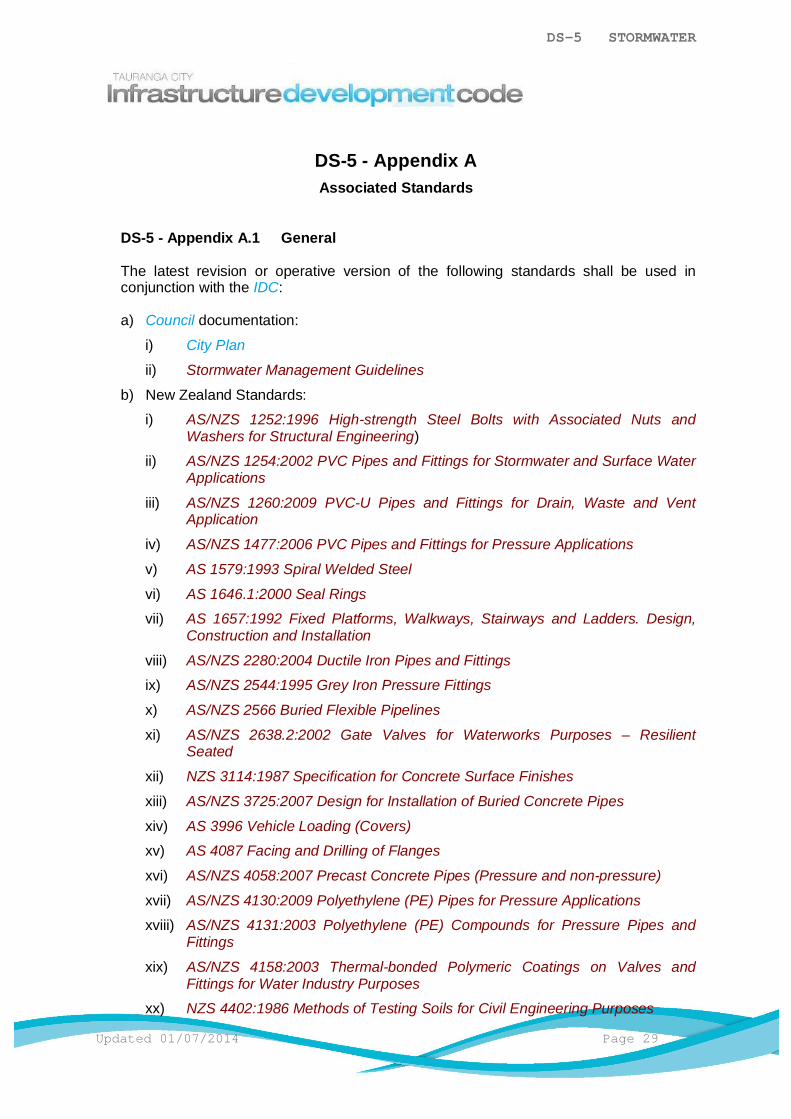
DS-5 STORMWATER
Updated 01/07/2014 Page 29
DS-5 - Appendix AAssociated Standards
DS-5 - Appendix A.1 General
The latest revision or operative version of the following standards shall be used inconjunction with the IDC:
a) Council documentation:
i) City Plan
ii) Stormwater Management Guidelines
b) New Zealand Standards:
i) AS/NZS 1252:1996 High-strength Steel Bolts with Associated Nuts andWashers for Structural Engineering)
ii) AS/NZS 1254:2002 PVC Pipes and Fittings for Stormwater and Surface WaterApplications
iii) AS/NZS 1260:2009 PVC-U Pipes and Fittings for Drain, Waste and VentApplication
iv) AS/NZS 1477:2006 PVC Pipes and Fittings for Pressure Applications
v) AS 1579:1993 Spiral Welded Steel
vi) AS 1646.1:2000 Seal Rings
vii) AS 1657:1992 Fixed Platforms, Walkways, Stairways and Ladders. Design,Construction and Installation
viii) AS/NZS 2280:2004 Ductile Iron Pipes and Fittings
ix) AS/NZS 2544:1995 Grey Iron Pressure Fittings
x) AS/NZS 2566 Buried Flexible Pipelines
xi) AS/NZS 2638.2:2002 Gate Valves for Waterworks Purposes – ResilientSeated
xii) NZS 3114:1987 Specification for Concrete Surface Finishes
xiii) AS/NZS 3725:2007 Design for Installation of Buried Concrete Pipes
xiv) AS 3996 Vehicle Loading (Covers)
xv) AS 4087 Facing and Drilling of Flanges
xvi) AS/NZS 4058:2007 Precast Concrete Pipes (Pressure and non-pressure)
xvii) AS/NZS 4130:2009 Polyethylene (PE) Pipes for Pressure Applications
xviii) AS/NZS 4131:2003 Polyethylene (PE) Compounds for Pressure Pipes andFittings
xix) AS/NZS 4158:2003 Thermal-bonded Polymeric Coatings on Valves andFittings for Water Industry Purposes
xx) NZS 4402:1986 Methods of Testing Soils for Civil Engineering Purposes

DS-5 STORMWATER
Page 30 Updated 01/07/2014
xxi) NZS 4404:2010 Land Development and Subdivision Infrastructure
xxii) AS/NZS 4441:2008 Oriented PVC (PVC-O) Pipes for Pressure Applications
xxiii) NZS 4442:1988 Welded Steel Pipes and Fittings for water, sewage andmedium pressure gas
xxiv) AS/NZS 4765:2007 Modified PVC (PVC-M) Pipes for Pressure Applications
xxv) AS/NZS 5065:2005 Polyethylene and Polypropylene and Fittings for Drainageand Sewerage Applications
xxvi) NZS/BS 5163:1986 Specification for Predominantly Key-Operated Cast IronGate Valves for Waterworks Purposes
xxvii) BS EN 124 Vehicle Loading (Covers)
xxviii) NZTA M/7 Roadmarking Paints
c) Other reference material:
i) Resource Management Act 1991
ii) New Zealand Building Act
iii) New Zealand Health and Safety in Employment Act 1992
iv) IPENZ Procedure for Hydrological Design of Urban Stormwater Systems,December 1980
v) New Zealand Building Code Handbook and Approved Documents section E1 -Surface Water
vi) Auckland Regional Council - TP10 Stormwater Management Devices, DesignGuidelines Manual)
vii) Auckland Regional Council - TP124 Low Impact Design Manual
viii) Christchurch City Council - Waterways, Wetlands and Drainage Guide
ix) Part B, North Shore City Council – Bioretention Guidelines 2008.
x) New Zealand Ministry for the Environment Climate Change Effects andImpacts Assessment Publication 2008.
xi) New Zealand Department of Labour Approved Code of Practice for Safety inExcavation and Shafts for Foundations – April 2000

DS-5 STORMWATER
Updated 01/07/2014 Page 31
DS-5 - Appendix BDesign Rainfall Tables
DS-5 - Appendix B.1 General
The Table A Climate-Adjusted Design Rainfall Depth Estimate and Table BClimate-Adjusted Design Rainfall Intensity Estimate are applicable to the Tauranga Cityarea.
Table A: Climate-Adjusted Design Rainfall Depth Estimate (2055) in mm
Return DURATION
Period(years)
10minutes
20minutes
30minutes 1 hour 2 hours 6 hours
12hours
24hours
48hours
X2.33 13 20 25 33 45 71 91 115 1305 18 26 35 49 69 102 128 150 172
10 21 33 44 65 90 131 158 183 21220 24 40 52 80 112 159 189 219 25550 30 48 64 100 141 197 230 273 320
100 33 56 72 115 163 225 259 320 377
Note: For 2.33 years read annual.
Table B: Climate-Adjusted Design Rainfall Intensity Estimates (2055) inmm/hour
Return DURATIONPeriod(Years)
10minutes
20minutes
30minutes 1 hour 2 hours 6 hours
X2.33 78 60 50 33 23 125 108 78 70 49 35 17
10 126 99 88 65 45 2220 144 120 104 80 56 2750 180 144 128 100 71 33
100 198 168 144 115 82 38
Note: For 2.33 years read annual. For intermediate durations refer to DS-5 Appendix C.1General.
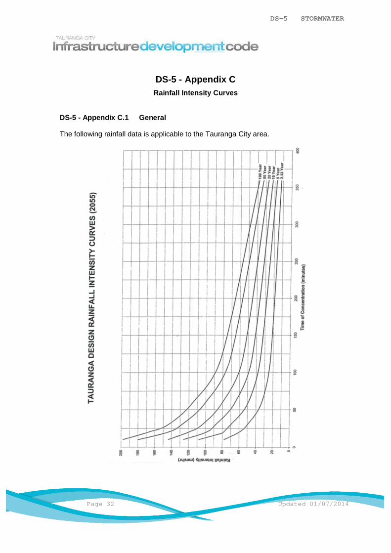
DS-5 STORMWATER
Page 32 Updated 01/07/2014
DS-5 - Appendix CRainfall Intensity Curves
DS-5 - Appendix C.1 General
The following rainfall data is applicable to the Tauranga City area.

DS-5 STORMWATER
Updated 01/07/2014 Page 33
DS-5 - Appendix DDisposal Of Stormwater By Ground Soakage
DS-5 - Appendix D.1 General
The disposal of stormwater from roofs, parking access and manoeuvring areas hashistorically been successfully undertaken by discharging the stormwater to drilledsoakholes or soakpits on private property.
However, such disposal methods have contributed to land instability and the creation ofnuisance due to groundwater seepage in elevated urban areas on the edge of TaurangaHarbour.
The degree of success and long-term serviceability of such soakage systems is alsodependent on the presence of permeable sub-soils (and their permeability), theconstruction of the soakage system and the amount of maintenance undertaken.
The soils present in the Tauranga City area vary, with the more permeable soils likely toexist adjacent to Tauranga Harbour, on elevated ground at Te Puke, along the coastalmargins where sand-derivative soils are present, at Pukehina, and on most elevatedrural areas (generally east of Te Puke).
Some areas of Tauranga City are suitable for on-site disposal of stormwater by groundsoakage. Traditionally, building at Mount Maunganui and Papamoa has used soakpitsconstructed from porous concrete liners, while in elevated areas adjacent to TaurangaHarbour holes were augered down through the Rotoehu Ash (soakage) layer and into anunderlying marker bed, the Hamilton Ash (“chocolate”) layer, to achieve adequatesoakage.
For Mount Maunganui and Papamoa the stormwater disposed of by soakage helpsrecharge the groundwater and prevent salt-water intrusion into the water table. InTauranga the stormwater is disposed of into a porous ash layer within the soil profile. Asboth communities developed stormwater infrastructure was sized, in general, to cater forstormwater generated on roads and not from residential lots.
With the intensification of development, the ability of the land to deal with the increasingvolumes of stormwater generated has, in some cases, become compromised with theresults affecting both the subject property and adjacent properties.
In Mount Maunganui these off-site effects have mainly been overland flows into adjacentproperties and in some cases inundation of buildings during significant rainfall. InTauranga off-site effects have resulted in elevated groundwater levels with surface“breakout” in some areas, overland flows when the soakhole capacity has beenexceeded and, in some cases, slope failure due to erosion from overland flows and/orelevated pore pressures within the soil profile.
Accordingly, the use of ground soakage for the disposal of stormwater is no longerappropriate in some areas.
DESIGN STANDARDDS-6 WASTEWATER
TABLE OF CONTENTS
DS-6.1 General ..............................................................................................................1
DS-6.2 Minimum Requirements ......................................................................................1
DS-6.3 Regional Council Requirements .........................................................................1
DS-6.4 Design ................................................................................................................1
DS-6.5 Conveyance - Wastewater System .....................................................................3
DS-6.6 Collection .........................................................................................................12
DS-6.7 Further Considerations .....................................................................................17
DS-6.8 Wastewater Treatment Design .........................................................................18
DS-6.9 Wastewater Pump Stations ..............................................................................18
DS-6.10 Private Pump Stations ....................................................................................21
DS-6.11 Receiving Reticulation ....................................................................................22
DS-6.12 Rising Mains ...................................................................................................22
DS-6.13 Pump Station Layout ......................................................................................23
DS-6.14 Fittings and Materials .....................................................................................23
DS-6.15 Pump Station Services ...................................................................................23

DS-6 WASTEWATER
Updated 01/07/2014 Page 1
DS-6.1 General
The primary goal of a wastewater drainage system is to convey wastewater from urbanareas to the Council wastewater treatment plants. The management of wastewater has afunctional role in the urban and rural environments and also has important cultural,ecological and environmental implications. The core design principals of a wastewatersystem must be carefully managed in order to avoid problems relating to public health andpollution of water bodies. If the wastewater system is managed in this way, the impact on thesafety of the public and the environment is less.
Understanding the implications of the future land use and its design elements, such as theextent of effluent disposal is important and shall be taken into account.
DS-6.2 Minimum Requirements
Designs shall provide for a wastewater system that:
a) Complies with the operative City Plan and Infrastructure Development Code (IDC).
b) Is designed to acceptable urban design, landscaping and engineering standards.
c) Minimises, isolate or eliminates health and safety hazards during both its constructionand its use.
d) Minimises, isolates or eliminates any adverse ecological and environmental effects.
e) The wastewater system shall be located in areas that are geotechnically suitable for thesystem proposed.
Note: Where confirmation of this requirement is not clear a certification statement from aCategory 1 Geo-Professional may be required.
DS-6.3 Regional Council Requirements
Areas not served by a Council owned piped reticulation system (rural and mostrural/residential areas) shall comply with the Bay of Plenty Regional Council On Site EffluentTreatment Regional Plan either as a permitted or discretionary activity. Other factors such asodour and air pollution shall also be considered.
Internal reticulation to sewage treatment and effluent disposal systems shall be installed inaccordance with the New Zealand Building Code and the Bay of Plenty Regional CouncilRegional Plan for On Site Effluent Treatment.
Soakholes for the disposal of septic tank effluent are not a permitted activity in terms of theBay of Plenty Regional Council Regional Plan.
Contact the Bay of Plenty Regional Council for more information.
DS-6.4 Design
The following shall apply:
DS-6 WASTEWATER
Page 2 Updated 01/07/2014
a) Unless otherwise approved by Council, the design of the wastewater system shall be inaccordance with the IDC but may be supplemented by the documents noted in DS-6 ApxA.1 General.
b) A computer modelling system approved by Council may also be utilised.
Detailed design shall be required at the time of Development Works Approval. Where noDevelopment Works Approval is required, Council approval shall be obtained at a timerequired by Council and before the construction of the system.
DS-6.4.1 Calculation of Flows
The following shall apply:
a) Wastewater flows are a function of water consumption, infiltration and direct entry ofstormwater, which in turn are a function of the age of the system and the quality ofmaintenance. The wastewater system shall be designed to eliminate intrusion ofstormwater & groundwater.
b) Where part or all of the catchment is serviced or will be serviced by a trunk main tobe constructed at a later date, Council may agree to this area being excluded fromthe calculation. The flow from all portions of the upper catchment within theTauranga City boundary shall be calculated assuming full development to the zonespotential.
c) In residential areas, the wastewater system shall be designed and constructed usingthe following parameters:
i) Population density of 50 people/ha.
ii) Average dry weather flow of 210L/person/day and a dry weather diurnal peakfactor of 2.5.
iii) Dilution/infiltration factor of 2 for wet weather.
iv) Peak hourly flow 0.61 L/sec/ha.
d) For design populations of 1000 people or more, a reduced peaking factor may bediscussed and agreed with Council.
e) In industrial or commercial areas, the wastewater system shall be designed using adischarge rate of 0.7 L/sec/hectare.
Note: These figures include both normal wastewater and trade wastes and include apeaking factor of 5 times average daily water flow (ADWF).
i) Notwithstanding the above, provision for trade waste shall be made byarrangement with the Council and shall be subject to the provisions of theappropriate Trade Waste Bylaw.
The industry type will not necessarily coincide with the zoning classificationshown in the City Plan, but the zoning, particularly where effluent discharge isa performance standard, may be used to indicate the minimum design flowwhere more detailed information is not available.
ii) It may be desirable to provide additional capacity if the developer wishes towiden the range of industries to be located in a development area. Howeverthe capacity of the existing receiving facility may be a controlling factor and thefinal decision will rest with Council.

DS-6 WASTEWATER
Updated 01/07/2014 Page 3
iii) The design of wastewater disposal systems for "wet" industries (very heavywater users) shall be based on the specific requirements for that industry.
f) For commercial flows refer to DS-1 - Apx A.1 General.
DS-6.4.2 Hydraulic Design
The following shall apply:
a) The hydraulic design of the system shall be designed such that maximum designflows can be accommodated without surcharging the pipe network.
b) The hydraulic design of wastewater pipelines shall be based on tables for thehydraulic design of sewers and pipelines or on graphs or other representation of thesame methods based on the Colebrook White or Manning's Formulae.
c) The pipe roughness coefficient Ks used in the design shall be as shown in NZS4404Table 5.2.
Table 1: Wastewater Pipe Roughness Coefficients
Material Colebrook Whiteco-efficient
Mannings Roughnessco-efficient
PVC-U 0.6 0.011PE 0.6 0.011GRP 0.6 0.011Cement Lining 1.5 0.012PE or Epoxy Lining 0.6 0.011
DS-6.4.3 Maximum Velocity
Maximum velocity flow shall be 3.0m/sec (peak wet weather flow pipe full).
Where a steep grade that will cause a velocity greater than that specified is unavoidable,refer to the Water Services Association of Australia : Sewerage Code of Australia : WSA02 – 2002 for precautions and design procedures.
DS-6.5 Conveyance - Wastewater System
The wastewater system shall be a piped reticulation system.
DS-6.5.1 Piped Reticulation
The piped reticulation system shall be designed to the following minimum requirements:
a) It must comply with DS-1 - Appendix A.1 General.
b) Reticulation mains shall be no smaller than 150mmØ.
c) Trunk mains shall be ³ 225mmØ.

DS-6 WASTEWATER
Page 4 Updated 01/07/2014
d) The minimum pipe size for connections or laterals shall be as follows:
1 or 2 independent dwelling unitsMore than 2 independent dwelling unitsCommercial and industrial lotsReticulation servicing residential lotsCarriageway crossings
– 100mmØ– 150mmØ– 150mmØ– 150mmØ– 150mmØ
e) Under no circumstances shall the pipe size be reduced on any downstream section.
f) Manholes are required at each:
i) Intersection of pipes (except for junctions between mains and laterals).
ii) Change of grade (except where vertical curves are used).
iii) Change of direction (except where horizontal curves are used).
iv) Combination of changes of pipe direction and grade (except where compoundcurves are used).
v) Change of pipe size.
vi) Change of invert level.
vii) Change of material (except for repair/maintenance locations).
viii) Discharge of a pressure main into a gravity system.
ix) Permanent or temporary end of a pipe system.
g) Each branch line (excluding connections) shall join the main line at a manholejunction.
h) In potentially unstable ground or where special protection is required, the pipelineshall be specifically designed including the choice of materials.
DS-6.5.2 Reticulation Layout
The following shall apply:
a) The alignment of wastewater reticulation shall be laid out to follow the road patternand either:
i) Be located clear of the carriageway.
ii) Be located clear of wheel tracks if within the carriageway.
b) Where this is not possible or practical, the main may be located:
i) On public land with approval from Council.
ii) Within private property parallel to and located between 1m and 1.5m from thefront, rear and/or side boundaries provided it avoids affecting futuredevelopment options available within the lot.
iii) On the low side of lots that have a cross-fall of more than 1.5m.
iv) Drainage reserves outside the 50 year return period storm event (2%AEP)area.

DS-6 WASTEWATER
Updated 01/07/2014 Page 5
c) Where the only option for location of reticulation is within the carriageway, thereticulation shall be located in the centre of the driving lane & designed to support an8.2 tonne design axle load.
d) Horizontal curved pipes shall only be used only where approved by Council. Designstandards for curved pipes can be found in Water Services Association of Australia :Sewerage Code of Australia : WSA 02 - 2002.
e) Vertical curves may be specified where circumstances provide a significant saving orwhere maintenance structures would be unsuitable or inconvenient. The curvaturelimitations for vertical curves can be found in the Water Services Association ofAustralia : Sewerage Code of Australia : WSA 02 - 2002.
f) Where an existing reticulation system exists, provision must be made for connectioninto this.
g) Where the reticulation is within a private way, right-of-way, or joint-owned access lotthe reticulation shall be located outside the logical wheel track alignment.
DS-6.5.2.1 Close Proximity Rules
T653 T654
The following shall apply:
a) Buildings or structures to be constructed close to a main or lateral/connectionshall comply with the requirements of T653 and T654. Where dispensation hasbeen granted for a building or structure to be built over a main orlateral/connection, foundations shall be designed by a Chartered ProfessionalEngineer.
b) No enclosed building or structure shall be sited over a manhole or closer than500mm from the outside wall of the manhole structure.
c) No building or concrete slab shall be constructed over a connection point to amain.
d) No buildings shall be constructed over a main if there is a connection closerthan 1.0m to the building unless the connection is relocated to the satisfaction ofCouncil.
e) Encroachment of removable, non-permanent structures e.g. carports, decks,fences may be approved by Council when the structure is designed and builtsuch that it can be dismantled easily in sections. The removal and re-erection ofthese structures shall be at no cost to Council. Council approval is required in allinstances. Council will assess each application on a case by case basis as thevariables at each site will not always be the same e.g. pipe size, trench detailsetc. Council may add a record to the property file of any such approval to ensurethat future property owners are aware of the approval and Council’s right tohave the structure removed at any time for the purposes of maintenance work,emergency work or upgrade work.
DS-6.5.3 Minimum Grades for Self-Cleaning
The following shall apply:

DS-6 WASTEWATER
Page 6 Updated 01/07/2014
a) The reticulation pipes within the wastewater management system shall be designedand constructed to at least the following minimum grades to achieve self cleansingas shown in DS-6.5.3 Table 2: Minimum Grades for Self-Cleaning.
b) Where the normal velocity and gradient limits cannot possibly be met, Council mayrequire certain additional works to ensure satisfactory operation of the system.
Table 2: Minimum Grades for Self-Cleaning
Trunk or Reticulation MainPipe Size (Ø) Minimum Grade (%)
150mm 0.55225mm 0.33300mm 0.25
Lateral ConnectionPipe Size ( Ø ) Minimum Grade (%)
100mm 1.65150mm 1.2
> 150mm 1.0
DS-6.5.4 Steep Grades
Scour blocks and trench stop configuration shall be detailed on the design drawings andshall be in accordance with the Standard Drawings. Spacing of scour blocks shall be inaccordance with DS-6.5.4 Table 3: Spacing of Scour Blocks.
Table 3: Spacing of Scour Blocks
Grade % Requirement Spacing (S) (m)15 – 35 Concrete bulkhead S = 100/Grade (%)
>35 Special design Refer to Council
Note: On flat grades where scour is a problem, sand bags are oftenused to stabilise the trench backfill.
Where the natural transfer of water from the trench into the surroundingground will not provide sufficient drainage, trench drainage shall beprovided to divert the water.
DS-6.5.5 Cover Over Pipelines
The following shall apply:
a) In private property:
i) The minimum cover shall be 600mm.ii) If the cover exceed 3m, specific design and approval is required.
DS-6 WASTEWATER
Updated 01/07/2014 Page 7
iii) The design of cover shall avoid affecting the future development optionsavailable within the lot.
iv) Where the reticulation lines are located in the front yards of lots, the invertlevel shall be deep enough so as not to interfere with any future drivewayconstruction.
b) In Road Zones:
i) Pipelines shall achieve 900mm of cover and be designed to support an 8.2tonne design axle load.
c) Where minimum cover cannot be achieved, specific design of pipe and cover isrequired.
DS-6.5.6 Loads on Pipes
The following shall apply:
a) All pipelines shall be designed to withstand all the likely loads that they may besubject to.
b) In the first instance, load parameters shall be designed to support an 8.2 tonnedesign axle load. Following this:
i) AS/NZS 3725 and AS 2566 shall be used as design guides as applicable.
ii) Any loads relating to backfill techniques, construction traffic, temporarystorage of materials and the like shall be incorporated into design parametersand construction methodology.
DS-6.5.7 Concrete Capping of Pipelines
Where minimum cover cannot be achieved, concrete capping may be used taking intoaccount pipe protection and road integrity requirements. Approval from Council isrequired for the use of concrete capping.
DS-6.5.8 Pipe Materials
Refer to AM-6 Wastewater.
DS-6.5.9 Pipe Joints
All pipelines shall be fully sealed by use of rubber joint rings or welding as appropriateunless otherwise approved by Council.
DS-6.5.10 Pipe Bedding and Backfill
T651
The following shall apply:
DS-6 WASTEWATER
Page 8 Updated 01/07/2014
a) Pipe bedding and backfill shall be specifically designed, shown on the detaileddesign drawings and submitted to Council for approval.
b) The design shall also include the compaction criteria to be used to certify the backfillhas been compacted to the required compaction standard.
c) All trench backfill under carriageways shall be designed and constructed to achievefor the required pavement layers strengths for the class of road it is beneath.
DS-6.5.11 Venting
The following shall apply:
a) The wastewater management system shall be ventilated to minimise the likelihood offoul gases accumulating in the drainage system.
b) In urban developments pipes will normally be adequately ventilated within privateproperty drainage via terminal vent stacks. However there are some situations whereadditional vent stacks may be required. These are:
i) Pumping stations.
ii) Manholes where pumping station rising mains discharge to a gravity pipe.
c) Vents and pump stations shall be located to avoid being a noise or odour nuisance tooccupants of buildings or likely building sites.
DS-6.5.12 Piped Reticulation Structures
The following shall apply:
a) This section describes the requirements for structures that may be needed inconveying wastewater through a reticulated system. These are:
i) Manholes.
ii) Rodding Eyes.
iii) Alternative structures as specifically designed.
b) The selection of a suitable location for these structures may influence the pipealignment. Generally a minimum clearance of 1.0m shall be provided clear of theopening around any structure that may allow entry for maintenance or rescueequipment. Council may determine other specific requirements subject to theindividual site’s characteristics.
DS-6.5.12.1 Manholes
T601, T602, T603, T604, T605, T606, T607, T608, T609, T610, T611, T612, T613
The following shall apply:
a) Manhole spacings shall not exceed 100m. The entire manhole structure shall belocated clear of all boundaries and at the end of all public reticulation mains.
b) The entire manhole structure shall be located clear of all boundaries.

DS-6 WASTEWATER
Updated 01/07/2014 Page 9
c) Manholes shall be located within Council property or Road Zones as often aspossible. They shall be clear of floodways, stormwater detention areas,stormwater secondary flowpaths and inter-tidal regions.
d) Manholes deeper than 5.0m to the pipe invert and shallow manholes may beused in certain circumstances subject to the approval of Council. Where amanhole is more than 5.0m deep it shall:
i) Be specifically designed.
ii) Have access steps installed.
iii) Incorporate clear warning that it is deep.
iv) Have a secure entrance.
v) Require larger diameter chambers and covers.
e) Standard 1050mmØ manhole risers are not suitable where the pipes are eitherlarger than 675mmØ or where multiple pipes enter a manhole causing loss ofthe manhole wall. Manholes shall be designed to maintain wall integrity in thesecircumstances.
f) Manholes shall not be located within the road carriageway unless approved byCouncil.
g) All manholes shall have an entry safety grill fitted.
h) All standard manholes shall be constructed as detailed on the StandardDrawings.
DS-6.5.12.2 Manhole Sizing
The following shall apply:
a) The standard internal diameter of circular manholes is 1050mmØ and thepreferred nominal internal diameters are 1050mmØ, 1200mmØ and 1500mmØ.
b) When considering the appropriate manhole diameter consideration shall begiven by the Designer to the base layout to ensure hydraulic efficiency andadequate working space in the chamber.
c) Where the effective working space is reduced by internal drop pipes, a largerdiameter may be required.
d) Where there are several inlets, consultation with Council on the layout of thechamber is recommended.
DS-6.5.12.3 Benching
The following shall apply:
a) Benching shall be provided in the base of each manhole that provides a safeplace to stand for maintenance purposes.
b) Benching shall be close to flat with a cross fall (3H:1V upslope failure zone) intothe manhole pipe system for drainage purposes.
c) Channels shall have a minimum inside radius of 300mm.

DS-6 WASTEWATER
Page 10 Updated 01/07/2014
DS-6.5.12.4 Internal Falls through Manholes
The following shall apply:
a) Reticulation pipes:
i) The minimum internal fall through a reticulation channel in a manhole shallbe as outlined in DS-6.5.12.4 Table 4: Minimum Internal Fall Through aManhole.
ii) The maximum benched fall through a manhole shall be 600mm.
iii) Where the outlet diameter at a manhole is greater than the inlet diameter,the minimum fall through the manhole shall be not less than the differencein diameter of two pipes, in which case the pipes shall be aligned soffit tosoffit.
iv) For manholes where the maximum internal fall of 600mm across the baseof the manhole is exceeded due to a large difference between the levels ofincoming and outgoing pipes then internal or external drops shall beprovided as shown in the Standard Drawings.
b) Lateral connections to manholes:
i) The invert of a lateral must connect to the manhole at a level no lower thanthe average of the soffit levels of the main inlet and outlet pipes.
ii) The maximum angle of deflection of lateral into the manhole main channelshall be 90 degrees.
Table 4: Minimum Internal Fall Through a Manhole
Deflection angle at manhole Degrees(°)
Minimum additionalfall (mm)
0 to 30>30 to 60>60 to120
305080
DS-6.5.12.5 Allowable Deflection Through Manholes
The maximum allowable deflection through a manhole shall be as outlined inDS-6.5.12.5 Table 5: Allowable Deflection Through Manholes.
Table 5: Allowable Deflection Through Manholes
Pipe size (Ø) Maximum deflection (º)
150-300mm150-300mm
Up to 120º for internal fall along manholechannelUp to 150º when using an internal or externaldrop structure

DS-6 WASTEWATER
Updated 01/07/2014 Page 11
DS-6.5.12.6 Effect of Steep Grades on Manholes
Where a pipe of grade >7 % drains to a manhole, the following precautions shall betaken:
a) Steep grades shall be continuous through the manhole at the same grade.
b) Depth of a manhole to exceed 1.5m to invert for 150mmØ and 225mmØ pipes.
c) Depth of a manhole is to exceed 2.0m deep for 300mmØ pipes.
d) Change of direction at the manhole is not to exceed 45º.
e) No drop junctions or verticals shall be incorporated in a manhole.
f) Inside radius of channel inside a manhole is to be greater than 6 times the pipediameter and benching is to extend 150mm above the top of the inlet pipe.
g) To avoid excessively deep channels within manholes, steep grades (>7 %) shallbe "graded-out" at the design phase where practicable. The design of pipelineson gradients over 7% must be agreed with Council.
h) Benching of channels to ensure that the final platform is parallel with the mainchannel so maintenance workers are able to stand comfortably on a flat surface.The benching shall be sloped towards the channel.
DS-6.5.12.7 Flotation
In areas of high water table, all manholes shall be designed to provide a factor ofsafety against flotation of 1.25.
DS-6.5.12.8 Access Steps
T603
Manhole steps shall comply with the Standard Drawings and AM-6 Wastewater.Wastewater manhole steps shall be located above the downstream outlet pipe.
DS-6.5.12.9 Covers
T604, T605, T606, T607
The following shall apply:
a) Manhole covers with a minimum clear opening of 600mm in diameter shall beused.
b) Non-Rock covers must be used on all Level 2 (or primary arterial) roads.
c) Refer to AM-6 Wastewater for manhole cover type.
d) All covers shall be painted with New Zealand Transport Agency (NZTA)Standard approved "white" road marking paint.

DS-6 WASTEWATER
Page 12 Updated 01/07/2014
DS-6.5.12.10 Areas Subject to Flooding
The following shall apply:
a) The top of manholes in areas subject to flooding or located in a stormwatersecondary flowpath shall be raised at least 300mm above the 50 year returnperiod storm event (2%AEP) where practicable. This may require local groundrecontouring to suit.
b) Sealed/watertight access covers may be required where the possibility ofsurcharge exists or the manhole is located:
i) In a hardstand area (e.g. in a carriageway or walkway).
ii) Along a watercourse that is subject to flooding above the level of the cover
iii) In tidal areas or in any location where surface waters could inundate thetop of a manhole.
DS-6.5.12.11 Internal and External Drop Manholes
T608, T609
The following shall apply:
a) All drop connections to new wastewater manholes shall be constructed asdetailed in the Standard Drawings.
b) Internal drop connections will be permitted only by written approval and mayrequire the installation of a 1200mmØ manhole. Internal drop connections maybe allowed when working in sand country with potentially high groundwater anda resultant danger to the carriageway exists.
c) The minimum height for drop connections shall be 600mm.
DS-6.5.12.12 Rodding Eyes
T620, T621
The following shall apply:
a) A rodding eye shall be required at the ends of some lateral pipes installedbetween a property connection point and the wastewater main.
b) PVC-U bends up to 45° are acceptable.
c) A standard manhole frame and cover shall be installed over the entry pointwhen not located in a hardstand area. A fire hydrant base and rodding eye covershall be used in hardstand areas.
d) All covers must be painted with New Zealand Transport Agency (NZTA)Standard approved "white" road marking paint.
DS-6.6 Collection
T630, T631, T632, T633, T634
DS-6 WASTEWATER
Updated 01/07/2014 Page 13
This section describes the requirements for collection of wastewater. These are categorisedas:
a) Property service connections.
b) Alternative collection methods.
DS-6.6.1 Property Service Connections
A connection is the point of union between a property’s private drain and the publicwastewater network. Private drainage generally extends to the property boundary atwhich point Council accepts responsibility for the downstream pipelines.
DS-6.6.2 Minimum Requirements
Property service connections shall be designed to the following minimum requirements:
a) Each lot shall be served by one service connection.
b) Any individual lot/property connection shall be designed and located to suit theexisting and future development scenarios and where possible sized, located anddesigned to meet the service of the whole property (land parcel), but as a minimumthe building platform.
c) Any connections shall be located to service the lowest practical building platform onthe property.
d) The design shall specify the requirements for the property connections including planlocation, lot contours and invert level at property boundary or junction with the mainas applicable.
DS-6.6.3 Private Drainage
Generally all wastewater pipes installed between a building and the connection point toCouncil’s wastewater network are private assets. The Building Act requires that aBuilding Consent shall be obtained for their installation or alteration and that this workmust only be carried out only by a registered drainlayer.
The following shall apply:
a) Further approval must also be obtained from Council before these drains may beconnected to the wastewater network. Application for this shall be on Council's WaterSupply / Drainage / Vehicle Crossing Connection Application Form.
b) All connections to Council infrastructure shall be carried out only by a CouncilLicensed Contractor.
DS-6.6.4 Connection Locations
Connections shall be:
a) Clear of obstructions, e.g. trees, tree roots, paved areas.
b) Easily accessible for future maintenance.

DS-6 WASTEWATER
Page 14 Updated 01/07/2014
c) Clear of any known future developments, e.g. swimming pools or driveways.
d) For infill subdivisions, particularly where upgrading of existing 100mmØ connectionsin sound condition and at reasonable grades would be impractical, up to fourdwelling units may be connected subject to Council approval.
DS-6.6.5 Connection Depth
T630, T631
The following shall apply:
a) Connection depths shall be set to drain the whole serviced area recognising thefollowing factors:
i) Any connection points shall have a minimum cover of 600mm and be nodeeper than 1.5m. (Deeper connections may be installed in somecircumstances but only with the prior approval of Council).
ii) Surface level at plumbing fixtures of buildings (existing or proposed).
iii) Depth to invert of pipe at plumbing fixture or intermediate points.
iv) Invert of public main at junction point.
v) Allowance for crossing other services.
vi) Allowance for minimum gradients of laterals and private drainage.
vii) Lateral junctions installed at minimum of 45° (vertical) to main.
b) The designed invert level at the connection shall be no higher than the lowestcalculated level consistent with these factors.
DS-6.6.6 Installation of Connections
T630, T631, T632, T633, T634
The following shall apply:
a) The end of each connection pipe shall be sealed with a solvent-welded cap paintedred if the connection does not occur immediately.
b) Where the inspection is servicing a property containing multiple residential units thena surface-accessible inspection chamber such as a manhole, rodding eye or otherCouncil approved structure shall be installed.
c) Each connection point shall be marked with a 50mm x 50mm timber stake paintedwhite which shall extend from the invert to a minimum of 300mm above finishedground level. A red marker tape labelled "sewer" shall be attached to the connectionpipe, brought up and tied to the top of the stake.
DS-6.6.7 Connection Destinations
Each service connection shall connect to one of the following points of discharge. Themechanisms are listed in order of preference.
DS-6 WASTEWATER
Updated 01/07/2014 Page 15
Where the main is within the property boundary a separate connection shall be providedto each lot.
a) Connections to wastewater mains greater than 5.0m deep will not be approved. Inthese cases a high-level wastewater main will need to be constructed.
b) Connections to trunk mains will generally not be approved by Council.
DS-6.6.8 Lateral Configurations
T637, T638, T639, T640, T641, T642
To provide a service connection to each lot, a minimum 100mmØ line shall be extendedfrom the main reticulation system to terminate within the property boundary at aminimum distance of 1.0m from the front and side boundaries whether created bycross-lease, unit title or fee-simple subdivision.
These connections shall also form part of the public system to the site boundary and bebrought up to within 1.2m of the final ground surface level.
In addition the following shall apply:
a) For a lateral providing a service connection for 1 lot connecting to a manhole refer toT637.
b) For a lateral providing a service connection for 2-6 lots connecting to a manhole referto T638.
c) For a lateral providing a service connection for 1 lot connecting to a main refer toT639.
d) For a lateral providing a service connection for 2 lots connecting to a main refer toT640.
e) Where lateral is over 50m long or the number of connections exceeds 6 lots, normalwastewater reticulation conditions apply.
f) Where practicable and where the connection is within 5m of a manhole theconnection shall be to the manhole.
g) Where the main is within the property boundary a separate connection shall beprovided to each lot.
h) All connections directly to the main shall be made using factory made fittings.
i) For major land use development where significant privately owned reticulation works(i.e. not being vested with Council) are being constructed and are connecting intoCouncil infrastructure, all works shall be designed and constructed in accordancewith the IDC requirements, however the reticulation will remain private.
DS-6.6.9 Infill Subdivision – 3 Lots or Less (Excludes Existing Lot)
It is recognised that infill subdivisions require flexibility in their reticulation layout.However, normal trade practices and standards are needed to ensure that the desiredservice life is achieved.
a) Reticulation of infill subdivisions shall comply with the following criteria:

DS-6 WASTEWATER
Page 16 Updated 01/07/2014
i) Drainage within the parent lot shall remain private and be protected by anappropriate easement.
ii) Drainage lines shall be separated at the point of connection to the Council’sreticulation system and remain separate for each lot unless specific approvalis gained from Council.
iii) Infill subdivisions shall be reticulated on a site-by-site basis.
iv) For minor infill subdivision type works, all private drainage works shall beconstructed in accordance with the NZ Building Code regulations.
b) Infill subdivisions shall be reticulated on a site by site basis to the approval ofCouncil.
c) Lateral connections shall be constructed or upgraded in accordance with the IDC.This lateral can be vested in Council and provide each lot with the same standard ofindividual connection as new ‘greenfields’ lots.
d) Where this is considered impractical or unnecessary, the Consent Holder may makeapplication to Council for the lateral to remain private within an appropriateeasement. However common private drains are not encouraged so as to alleviate thefriction that sometimes occurs between neighbours when shared services areinvolved.
e) Drainage lines shall be separated at the point of connection to Council’s reticulationsystem and remain separate for each lot unless specific approval is granted byCouncil. Where the main is within a neighbour's property, the new junction may beinstalled immediately within the property being subdivided.
DS-6.6.10 Multi-Unit Properties (Such as Apartment Buildings and BodyCorporate Developments)
a) For multiple occupancies (unit title, cross lease or company lease) service of thewhole property shall be achieved by providing a single point of connection to thewastewater system. Connection of the individual units is by joint service pipes ownedand maintained by the body corporate, tenants in common or the company as thecase may require. In this instance the whole of the multiple occupancy shall beregarded as a single lot. All drainage within the development boundary would beprivate.
b) Alternatively, if authorised by Council, developers may have the option of providingdrainage facilities to individual titles or tenements in new developments by extendingthe public line into the lot and providing a separate lateral/connection to each unit. Ifso all internal drainage shall be in accordance with the IDC. Easements shall becreated at Council’s discretion and to Council standards.
c) Where multi-unit developments are proposed, a single 150mmØ lateral/connectionwill be required. Multi-unit developments will generally be required to upgradeexisting laterals if less than 150mmØ. The connection shall include asurface-accessible inspection chamber or manhole immediately inside the boundary.
DS-6.6.11 Commercial and Industrial Connections
The following shall apply:
a) All commercial and industrial lots shall be provided with a wastewater connection.
DS-6 WASTEWATER
Updated 01/07/2014 Page 17
b) Pollutants and contamination issues shall be identified and managed to thesatisfaction of Council though the Building Consent Process.
DS-6.6.12 Connection to Existing Council Reticulation
Approval shall be obtained from Council before connection can be made to thewastewater network. Application for this shall be on Council's Water Supply / Drainage /Vehicle Crossing Connection Application Form.
All connections to Council infrastructure shall be carried out only by a Council LicensedContractor.
DS-6.7 Further Considerations
The following shall also be considered as part of the design process:
a) DS-6.7.1 Trenchless Technology
b) DS-6.7.2 Access Requirements
c) DS-6.7.3 Easements
d) DS-6.7.4 Rural and Rural-Residential Zones
DS-6.7.1 Trenchless Technology
Trenchless technology may be preferred or required for alignments passing through orunder:
a) Environmentally sensitive areas.
b) Built-up or congested areas to minimise disruption and reinstatement.
c) Railway and major road crossings.
d) Significant vegetation.
e) Vehicular crossings.Refer to CS-13 Trenchless Technology for information on trenchless technologyinstallation.
DS-6.7.2 Access Requirements
Where any assets are being created as part of a wastewater system that is to bemaintained by Council, legal and practical access shall be provided for maintenance. Forthe purpose of this standard provision legal and practical access shall be a minimum of a4m wide access width containing a 3m wide access path constructed to an all weatherstandard able to carry an 8.2 tonne design axle load.

DS-6 WASTEWATER
Page 18 Updated 01/07/2014
DS-6.7.3 Easements
Discussion with Council regarding easements is recommended early in the designphase.
An easement in gross will be required where a structure, pipe or other asset that formspart of the wastewater / stormwater / water supply system is to be vested in ormaintained by Council and is located within land not vested in Council or a Reserve.
An easement in gross may not be required where the structure, pipe or other asset is:
a) Located within 1.5m of a property boundary.
b) A wastewater pipeline less than 150mm in diameter
All easements shall allow for right of access for practical maintenance.
DS-6.7.4 Rural and Rural-Residential Zones
Refer to DS-6.3 Regional Council Requirements.
DS-6.8 Wastewater Treatment Design
These are to be specifically designed and approved by Council. Discussions with Councilshall be undertaken during the design phase.
DS-6.9 Wastewater Pump Stations
T660, T661, T662, T663, T664, T665, T666, T667, T668, T669, T670, T671, T672, T673,T674, T675, T676, T677, T678, T679, T680, T681, T682, T683
Wastewater pump stations convey wastewater from developed areas where natural landformand gradients do not allow for a gravity system to be used. It is important that’s factorsaffecting a pump station’s operation are understood as the effect of an overflow on thesurrounding area and/or watercourses is unacceptable due to important cultural, ecologicaland environmental implications as well as public health and pollution issues.
Detailed design shall be required at the time of Infrastructure Development Works Approval.Where no Infrastructure Development Works Approval is required Council approval shall beobtained at a time required by Council and before the construction of the system.
DS-6.9.1 Calculation of Flows
The following shall apply:
a) The pump station shall be sized to accommodate pumped flows from the totalforeseeable contributing catchment.
b) Each pump shall be sized such that the duty pump is capable of pumping themaximum design peak flow, calculated in accordance with DS-6.4.1 Calculation ofFlows.
DS-6 WASTEWATER
Updated 01/07/2014 Page 19
DS-6.9.2 Freeboard
The pump station finished lid levels shall be located no less than 300mm above the 100year return period storm event (1%AEP) flood level.
DS-6.9.3 Wet Well and Storage Chamber
T660, T661, T662, T663, T664, T665, T666, T667, T668, T669
The following shall apply:
a) These shall be as specified in the Standard Drawings.
b) Pump stations and vents shall be located to avoid being a noise or odour nuisance tooccupants of buildings or likely building sites.
c) Wet wells and storage chambers shall be designed to accommodate all anticipatedloadings and safely accommodate all maintenance and operations vehicles andpersonnel.
d) The wet well operational volume (volume between duty pump start and stop level)shall be designed at full catchment average dry weather inflow to limit pump starts toa maximum of 15 an hour based on the following formula:
Operational Volume (litres) = 900 x Q N
Q = Pumping Rate (l/s)N = Number of starts per hourOperational depth shall be a minimum of 1.5mmeasured from the invert of the inlet pipe.
e) The design and construction of the wet and storage well foundations shall ensurethat no more than 10mm effective long term total or differential settlement of thecompleted structure occurs and a factor of safety of 1.25 against flotation is obtained.Effects on adjoining infrastructure must be considered.
f) A geotechnical investigation report may be required by Council at the time of theapplication for Resource Consent or the development plan approval.
g) In determining the appropriate wet well diameter the minimum clearance betweenindividual pumps and side clearances shall comply with the manufacturer’srecommendations.
h) A minimum clearance of 100mm all round the well shall be provided at the lidentrance.
i) Where a separate well is considered necessary to accommodate emergency storagevolume it shall be designed to direct all flow to the outlet point and be self cleansing.
j) A hinged entry safety grill shall be fitted immediately under the wet well chamber lids.
DS-6.9.4 Pump Station Inlet Pipe
The following shall apply:

DS-6 WASTEWATER
Page 20 Updated 01/07/2014
a) The invert level of the gravity inlet pipe and emergency storage well shall be aminimum of 100mm above the standby pump start level to prevent surcharge of thesystem during normal operation.
b) Only one gravity pipe may discharge into the wet well and must include an isolationvalve. Where multiple inflows occur they must discharge to a receiving manhole,then into the wet well.
DS-6.9.5 Pump Selection
a) In calculating the system head losses the effects of all bends and fittings beyond thepump discharge bend shall be allowed for, together with rising main friction losses.Calculations of friction loss shall be carried out based on roughness ‘Ks’ values of1.5mm and 0.5mm to ensure that the selected pump is capable of operating over thisrange of duty points. (Colebrook White formula). Where the discharge is to anexisting rising main, the head shall be calculated to include the operating head in theexisting rising main. Council approval is required for any discharge into an existingrising main.
b) The system static head shall be based on the difference in level between the flangeof the pump discharge bend and the highest point on the rising main system.
c) The pump and rising main selection shall ensure the minimum velocity in the risingmain is 1.0m/sec and the maximum 2.0m/sec (at peak design discharge rate).
d) In selecting pumps the operating conditions shall correspond as closely as possiblewith the point of maximum pump efficiency. However final pump selection must beapproved by the Council to facilitate some standardisation of pump model andimpellor type and sizes.
e) Standard pump stations shall include 2 identical submersible Wastewater pumps,one as a duty pump and the other as a standby. Larger pump stations may requireadditional pumps.
f) The pump type shall be as specified in AM-6 Wastewater.
DS-6.9.6 Impellers
To prevent unnecessary blockage all pumps shall be fitted with an ‘N" impeller approvedby the Council. Where a mini pump station is constructed to service 5 lots or less, somedeparture from the IDC may be acceptable. However, approval is required from Council.
DS-6.9.7 Power Supply
T672, T673, T674, T675, T676, T677, T678, T679, T680, T681, T682, T683
All pumps shall be operated from a three-phase electrical power supply system.
DS-6.9.8 Control and Alarm Levels
Control and alarms levels shall be as outlined in Table 6: Control and Alarm Levels.

DS-6 WASTEWATER
Updated 01/07/2014 Page 21
Table 6: Control and Alarm Levels
Table 6: Control and Alarm Levels
Control Type Level
Low level alarm set to activate if the water level drops below cut out level formore than 1 minute
Pump stop level minimum submergence level of pumps
Duty pump start level 150mm below incoming wastewater invert level
Standby pump start level 100mm above duty cut-in level
High Level Alarm 100mm above stand-by cut-in level
Critical Alarm 100mm below spill level
DS-6.9.9 Emergency Storage
The following shall apply:
a) A total of 9 hours emergency storage must be provided upstream of the pumpingstation. This volume may include the upstream pipelines and manholes in calculatingstorage design but only after approval has been received from Council.
b) Specifically designed emergency storage chambers may be required to supplementthe volume provided by the collection system.
DS-6.10 Private Pump Stations
Smaller pump stations serving no more than 6 residential lots/dwellings are permissible.These pump stations shall:
a) Remain in private ownership
b) Be managed by a Body Corporate, Incorporated Society or other similar suitableownership/management structure
c) Be located on private property
d) Not be vested in Council
e) Be designed, constructed, operated & maintained to prohibit the general public cominginto direct contact with wastewater.
f) Not allow intrusion of stormwater & groundwater
g) Provide for a minimum of 9 hours onsite emergency storage based on the average dryweather flow, measured between the first stage alarm level & the point of overflow.Storage shall be in a designed chamber.

DS-6 WASTEWATER
Page 22 Updated 01/07/2014
h) Be located in areas that are geotechnically suitable for the system proposed. Thisrequires that no more than 10mm of settlement from the completed structure can occur& a safety factor of 1.25 against flotation is achieved.
i) The design life for the pump station plant shall be: 50 years except for electrical &mechanical components which shall have a minimum of 15 years & telemetry equipmenta minimum of 10 years.
DS-6.11 Receiving Reticulation
The gravity pipeline system to which the station discharges shall be designed toaccommodate the discharge of the duty pump operating in combination with the peak wet-weather flow from the adjoining gravity network.
DS-6.12 Rising Mains
T670
The following shall apply:
a) Only PE80 or PE100 pipes conforming to AS/NZS 4130 shall be used for rising mains.The required minimum pressure rating for a rising main shall be PN 10. Higher ratedpipes may be necessary. Other materials may be considered by Council.
b) Pipe selection shall take into account a 100 year service life and include derating due tooperating temperature and derating due to 107 cycles of cyclic water hammer loadcausing pressure swings from 1.5P to 0.5P.
c) A safety factor of not less than 1.25 shall also be included to determine the pipe pressureclass.
d) PE fittings fabricated from pipes shall be derated due to stress concentrations in thefabricated fittings. Manufacturer's recommendations shall be strictly followed with regardto the extent of derating required for each type of fabricated fitting.
e) Wherever possible, the rising main shall be designed on a positive gradient avoiding highand low points, therefore minimising the need for air release and scour valves.
f) PE pipes shall not be used for pipe bridges or within tunnels that are not backfilled unlessthe pipe is adequately anchored against flotation and thermal movement.
g) To accommodate all out of balance forces on the main its installation and design shall besimilar to that of a water main incorporating suitable anchorage at all changes ofdirection.
h) Rising mains shall be installed with "sewer" marker tape laid continuously 200mm abovethe rising main. The tape shall include a metallic wire that can be detected from thesurface.
i) Where any section of a rising main is installed by trenchless technology, tracer wire shallbe strapped to the pipe and fixed thereto by using a minimum of 2 complete wraps of50mm wide heavy duty adhesive tape at a maximum of 3.0m intervals. Wire traces shallbe continuous to allow an electrical current. Rising mains shall discharge into a receivingmanhole in accordance with the detail on the Standard Drawings.
j) Rising mains shall be a minimum of 76mm ID.
DS-6 WASTEWATER
Updated 01/07/2014 Page 23
DS-6.13 Pump Station Layout
T660
The Council’s typical wastewater pumping station layout details are shown on the StandardDrawings. Alternative layouts or prefabricated stations may be considered for approval on acase by case basis.
Pump stations shall be located on a separate lot solely for that purpose and be provided witha permanent access. An adequate turning area shall be incorporated adjoining the stationwet well and control cabinet to accommodate light commercial maintenance vehicles, unlessimmediate access to the roadway is possible. Control cabinets shall not be situated close tocarriageways in a position where it may be damaged by out of control vehicles.
In addition to the land required to construct a pump station, wet well and valve chamber, anarea of 5.0m x 5.0m shall also be made available to accommodate a biofilter either at thetime of construction or in the future.
DS-6.13.1 Secondary Storage Well
Where a secondary storage well is to be provided in addition to the pump wet well it shallbe positioned near the valve chamber to allow ready access.
DS-6.13.2 Receiving Manhole
The manhole immediately upstream of a pump station shall be a minimum of 1200mmØ.
DS-6.14 Fittings and Materials
Refer to AM-6 Wastewater.
DS-6.15 Pump Station Services
Pump stations require water supply and electrical services for operation.
DS-6.15.1 Water Supply
T671
The following shall apply:
a) All pump stations shall be provided with a water supply connection through astandard 25mm Council metered water connection and include a 25mm supply to astandard female Camlock hose connection located within, or directly outside thebackflow preventer cabinet.

DS-6 WASTEWATER
Page 24 Updated 01/07/2014
b) A second 25mm water supply connection (including 240 volt solenoid valve) shall beinstalled within the backflow preventer cabinet to facilitate supply to provide for awashdown sprayer be installed within the pump station wet well. For this purpose a25mm (ID) MDPE pipe shall also be installed from the solenoid valve into the wetwell with sufficient pipe to reach the centre of the well.
c) The water supply shall be protected by a reduced pressure zone 25mm backflowpreventer to comply with AS/NZ 2845.1:1998 and in accordance with DS-7 WaterSupply. This shall be located adjacent to the station and at least 300mm aboveground level.
DS-6.15.2 Electrical Supply
T672, T673, T674, T675, T676, T677, T678, T679, T680, T681, T682
Each pump station shall be fitted with a standard on site electrical control system andalarm/operational data system. These shall be compatible with the Council’s standardsystem. A copy of the standard details for these works is provided in the StandardDrawings.
DS-6.15.3 Telemetry
An electrical on-site telemetry system, assembled and installed in accordance with theCouncil’s standard specification shall be required.
DS-6.15.4 Access Requirements
Refer to DS-6.7.2 Access Requirements.
DS-6 WASTEWATER
Updated 01/07/2014 Page 25
DS-6 - Appendix AAssociated Standards
DS-6 - Appendix A.1 General
The latest revision or operative version of the following standards shall be used inconjunction with the IDC:
a) Council documentation:
i) City Plan
ii) TCC Trade Waste Bylaw
b) New Zealand Standards:
i) AS/NZS 1252:1996 High-strength Steel Bolts with Associated Nuts andWashers for Structural Engineering
ii) AS/NZS 1254:2002 PVC Pipes and Fittings for Stormwater and Surface WaterApplications
iii) AS/NZS 1260:2009 PVC-U Pipes and Fittings for Drain, Waste and VentApplication
iv) AS/NZS 1477:2006 PVC Pipes and Fittings for Pressure Applications
v) AS 1579:1993 Spiral Welded Steel
vi) AS 1646.1:2000 Seal Rings
vii) AS 1657:1992 Fixed Platforms, Walkways, Stairways and Ladders. Design,Construction and Installation
viii) AS/NZS 2280:2004 Ductile Iron Pipes and Fittings
ix) AS/NZS 2544:1995 Grey Iron Pressure Fittings
x) AS/NZS 2566 Buried Flexible Pipelines
xi) AS/NZS 2845.1:1995 Water Supply – Backflow Prevention Devices –Materials, Design and Performance Requirements
xii) NZS 3114:1987 Specification for Concrete Surface Finishes
xiii) AS/NZS 3725:2007 Design for Installation of Buried Concrete Pipes
xiv) AS 3996 Vehicle Loading (Covers)
xv) AS/NZS 4058:2007 Precast Concrete Pipes (Pressure and non-pressure)
xvi) AS 4087 Facing and Drilling of Flanges
xvii) AS/NZS 4130:2009 Polyethylene (PE) Pipes for Pressure Applications
xviii) AS/NZS 4131:2003 Polyethylene (PE) Compounds for Pressure Pipes andFittings
xix) AS/NZS 4158:2003 Thermal-bonded Polymeric Coatings on Valves andFittings for Water Industry Purposes
xx) NZS 4402:1986 Methods of Testing Soils for Civil Engineering Purposes
DS-6 WASTEWATER
Page 26 Updated 01/07/2014
xxi) NZS 4404:2010 Land Development and Subdivision Infrastructure
xxii) AS/NZS 4441:2008 Oriented PVC (PVC-O) Pipes for Pressure Applications
xxiii) NZS 4442:1988 Welded Steel Pipes and Fittings for water, sewage andmedium pressure gas
xxiv) AS/NZS 4765:2007 Modified PVC (PVC-M) Pipes for Pressure Applications
xxv) AS/NZS 5065:2005 Polyethylene and Polypropylene and Fittings for Drainageand Sewerage Applications
xxvi) NZS/BS 5163:1986 Specification for Predominantly Key-Operated Cast IronGate Valves for Waterworks Purposes
xxvii) BS EN 124 Vehicle Loading (Covers)
xxviii) NZTA M/7 Roadmarking Paints
c) Other reference material:
i) Resource Management Act 1991
ii) New Zealand Building Act
iii) New Zealand Health and Safety in Employment Act 1992
iv) Bay of Plenty Regional Council On-Site Effluent Treatment – Regional Plan
v) Sewerage Code of Australia WSA 02-002
vi) New Zealand Ministry for the Environment Climate Change Effects andImpacts Assessment Publication 2008.
vii) New Zealand Department of Labour Approved Code of Practice for Safety inExcavation and Shafts for Foundations – April 2000
DESIGN STANDARDDS-7 WATER SUPPLY
TABLE OF CONTENTS
DS-7.1 General ..............................................................................................................1
DS-7.2 Minimum Requirements ......................................................................................1
DS-7.3 Regional Council Requirements .........................................................................1
DS-7.4 Design ................................................................................................................1
DS-7.5 Conveyance - Reticulation Layout ......................................................................4
DS-7.6 Point of Supply .................................................................................................11
DS-7.7 Further Considerations .....................................................................................15
DS-7 WATER SUPPLY
Updated 01/07/2014 Page 1
DS-7.1 General
The primary objectives of a water supply system are to convey a potable drinkable supplyand to provide for firefighting purposes. The core design principals of a water supply systemshall be carefully managed in order to avoid issues relating to public health and the ability tosupply water for drinking and fire fighting purposes.
Understanding the implications of the future land use and its design elements, such as theextent of water demand, shall be taken into account.
DS-7.2 Minimum Requirements
Designs shall provide for a water supply system that:
a) Complies with the operative City Plan and Infrastructure Development Code (IDC).
b) Is designed to acceptable urban design, landscaping and engineering methods.
c) Minimises, isolates or eliminates health and safety hazard during both its constructionand its use.
d) Minimises, isolates or eliminates any adverse ecological and environmental effects.
e) The water supply system shall be located in areas that are geotechnically suitable for thesystem proposed.
Note: Where confirmation of this requirement is not clear a certification statement from aCategory 1 Geo-Professional may be required.
DS-7.3 Regional Council Requirements
Consultation and approval from Bay of Plenty Regional Council shall be undertaken for anyprivate water supply source i.e. bores, stream take etc.
DS-7.4 Design
T700
Unless otherwise approved by Council, the design of the water supply system shall be inaccordance with the IDC and may be supplemented by the documents noted in DS-7Appendix A.1 General.
A computer modelling system approved by Council may also be used.
Water reticulation design shall provide capacity for future development of land beyond theproposed subdivision and the existing reticulation assessed and upgraded if necessary tocater for both the proposed and future development. This may be varied by specificoperational requirements specified by Council.
Future development shall be designed based on ring main design, shall not compromisewater quality and avoid the development of pumped reticulation systems.

DS-7 WATER SUPPLY
Page 2 Updated 01/07/2014
Detailed design shall be required at the time of Infrastructure Development Works Approval.Where no Infrastructure Development Works Approval is required, Council approval shall beobtained at a time required by Council and before construction of the system.
DS-7.4.1 Water Supply Systems
Water supply systems shall consist of 2 main types:
a) Ordinary (residential).
b) Extraordinary (commercial, industrial and fire fighting).
In areas where a high level public supply zone does not exist, as in areas within a 30melevation of a Council reservoir, the developer shall supply an elevated storage reservoirto be vested in Council.
Council reserves the right to specify the size of the principal and rider watermains whereit deems departure from any standard is required.
DS-7.4.2 Residential (Excluding High Density Urban) Supply
The following shall apply:
a) The pipe network shall be designed to provide for annual, seasonal and peakdemand utilising the available pressures in the existing mains. It is the responsibilityof the Designer to verify what supply capacities are available to serve the proposeddevelopment.
b) The parameters for the residential use are:
i) Population density of 50 people/ha.
ii) 260 litres/person/per day and a design peak factor of 5 times.
iii) Peak hourly flow 0.75 L/sec/ha.c) Where a Resource Consent application or the City Plan sets a different minimum or
maximum density of lots per hectare, the design capacity shall be modified to reflectthat density per hectare.
DS-7.4.3 Commercial and Industrial Supply
The following shall apply:
a) Water Supply consumption shall be as outlined in Table 1: Water SupplyConsumption.
b) The water demand for commercial and industrial areas, high density urban areas orirrigation shall be analysed and specifically allowed for in the design but shall not beless than 0.75L/sec/ha.
c) The principal mains serving industrial and commercial areas shall be at least150mmØ laid in front of all industrial lots of the street. (This requirement may berelaxed in short cul-de-sacs as long as adequate fire fighting coverage is available.)
d) Where exact land use is not known a density flow of 0.75 L/sec/ha shall be used.
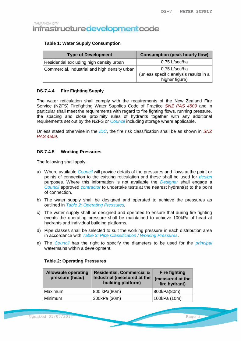
DS-7 WATER SUPPLY
Updated 01/07/2014 Page 3
Table 1: Water Supply Consumption
Type of Development Consumption (peak hourly flow)Residential excluding high density urban 0.75 L/sec/haCommercial, industrial and high density urban 0.75 L/sec/ha
(unless specific analysis results in ahigher figure)
DS-7.4.4 Fire Fighting Supply
The water reticulation shall comply with the requirements of the New Zealand FireService (NZFS) Firefighting Water Supplies Code of Practice SNZ PAS 4509 and inparticular shall meet the requirements with regard to fire fighting flows, running pressure,the spacing and close proximity rules of hydrants together with any additionalrequirements set out by the NZFS or Council including storage where applicable.
Unless stated otherwise in the IDC, the fire risk classification shall be as shown in SNZPAS 4509.
DS-7.4.5 Working Pressures
The following shall apply:
a) Where available Council will provide details of the pressures and flows at the point orpoints of connection to the existing reticulation and these shall be used for designpurposes. Where this information is not available the Designer shall engage aCouncil approved contractor to undertake tests at the nearest hydrant(s) to the pointof connection.
b) The water supply shall be designed and operated to achieve the pressures asoutlined in Table 2: Operating Pressures.
c) The water supply shall be designed and operated to ensure that during fire fightingevents the operating pressure shall be maintained to achieve 100kPa of head athydrants and individual building platforms.
d) Pipe classes shall be selected to suit the working pressure in each distribution areain accordance with Table 3: Pipe Classification / Working Pressures.
e) The Council has the right to specify the diameters to be used for the principalwatermains within a development.
Table 2: Operating Pressures
Allowable operatingpressure (head)
Residential, Commercial &Industrial (measured at the
building platform)
Fire fighting(measured at the
fire hydrant)Maximum 800 kPa(80m) 800kPa(80m)Minimum 300kPa (30m) 100kPa (10m)
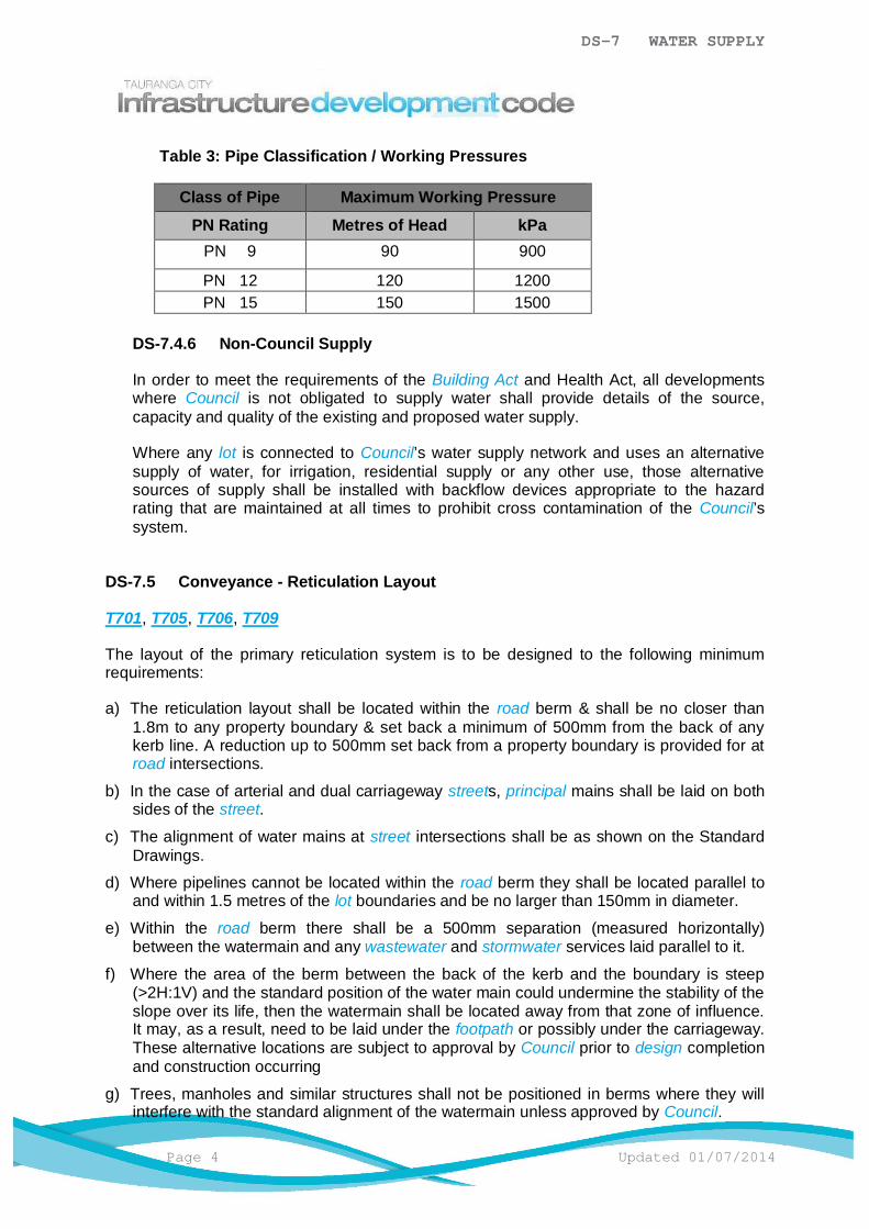
DS-7 WATER SUPPLY
Page 4 Updated 01/07/2014
Table 3: Pipe Classification / Working Pressures
Class of Pipe Maximum Working PressurePN Rating Metres of Head kPa
PN 9 90 900
PN 12 120 1200PN 15 150 1500
DS-7.4.6 Non-Council Supply
In order to meet the requirements of the Building Act and Health Act, all developmentswhere Council is not obligated to supply water shall provide details of the source,capacity and quality of the existing and proposed water supply.
Where any lot is connected to Council’s water supply network and uses an alternativesupply of water, for irrigation, residential supply or any other use, those alternativesources of supply shall be installed with backflow devices appropriate to the hazardrating that are maintained at all times to prohibit cross contamination of the Council’ssystem.
DS-7.5 Conveyance - Reticulation Layout
T701, T705, T706, T709
The layout of the primary reticulation system is to be designed to the following minimumrequirements:
a) The reticulation layout shall be located within the road berm & shall be no closer than1.8m to any property boundary & set back a minimum of 500mm from the back of anykerb line. A reduction up to 500mm set back from a property boundary is provided for atroad intersections.
b) In the case of arterial and dual carriageway streets, principal mains shall be laid on bothsides of the street.
c) The alignment of water mains at street intersections shall be as shown on the StandardDrawings.
d) Where pipelines cannot be located within the road berm they shall be located parallel toand within 1.5 metres of the lot boundaries and be no larger than 150mm in diameter.
e) Within the road berm there shall be a 500mm separation (measured horizontally)between the watermain and any wastewater and stormwater services laid parallel to it.
f) Where the area of the berm between the back of the kerb and the boundary is steep(>2H:1V) and the standard position of the water main could undermine the stability of theslope over its life, then the watermain shall be located away from that zone of influence.It may, as a result, need to be laid under the footpath or possibly under the carriageway.These alternative locations are subject to approval by Council prior to design completionand construction occurring
g) Trees, manholes and similar structures shall not be positioned in berms where they willinterfere with the standard alignment of the watermain unless approved by Council.

DS-7 WATER SUPPLY
Updated 01/07/2014 Page 5
In all cases where these standard layouts cannot be achieved, proposed alternative layoutsshall be referred to the Council for approval before installation. This referral shall include aproposed alternative.
DS-7.5.1 Close Proximity Rules
The following shall apply:
a) Buildings or structures to be constructed close to a main or lateral/connection shallcomply with the requirements of T753 and T754. Where dispensation has beengranted for a building or structure to be built over a main or lateral/connection,foundations shall be designed by a Chartered Professional Engineer.
b) Where a deviation or bend in a main is present, specific design is required. This shalladdress issues such as the impact of pressure loadings on the pipe, on pipe fittingsand associated restraints e.g. thrust blocks, anchor blocks etc.
c) No building or concrete slab shall be constructed over a connection point to a main.
d) No buildings shall be constructed over a main if there is a connection closer than1.0m to the building unless the connection is relocated to the satisfaction of Council.
e) Encroachment of removable, non-permanent structures e.g. carports, decks, fencesmay be approved by Council when the structure is designed and built such that it canbe dismantled easily in sections. The removal and re-erection of these structuresshall be at no cost to Council. Council approval is required in all instances. Councilwill assess each application on a case by case basis as the variables at each site willnot always be the same e.g. pipe size, trench details etc. Council may add a recordto the property file of any such approval to ensure that future property owners areaware of the approval and Council’s right to have the structure removed at any timefor the purposes of maintenance work, emergency work or upgrade work.
DS-7.5.2 Cover over Pipelines
The following shall apply:
a) The cover over water mains shall be as outlined in Table 4: Pipe Cover.
b) Under State Highways and rural roads a water main may traverse a water table etc,approval of the minimum cover shall form part of the Infrastructure DevelopmentWorks Approval.
c) The sections of main adjacent to a carriageway crossing may be deepened to allowthe required cover under the carriageway without the provision of vertical bends.Similar provisions shall be made to give the necessary cover over valve spindles i.e.350mm cover.
d) Pipe cover and depth shall be stated on the detailed design drawings.
e) Where minimum cover cannot be achieved, specific design of pipe and cover shallbe required to achieve the manufacturer's requirements and ensure adequateprotection of the pipe and fittings.
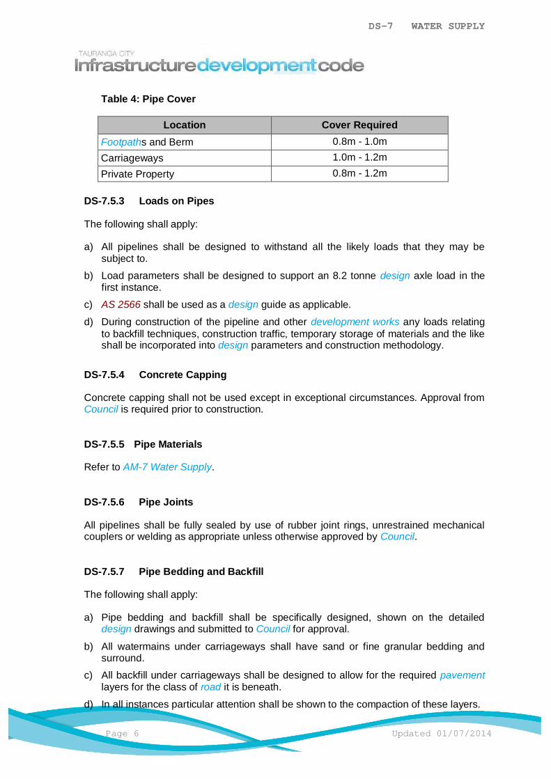
DS-7 WATER SUPPLY
Page 6 Updated 01/07/2014
Table 4: Pipe Cover
Location Cover RequiredFootpaths and Berm 0.8m - 1.0mCarriageways 1.0m - 1.2mPrivate Property 0.8m - 1.2m
DS-7.5.3 Loads on Pipes
The following shall apply:
a) All pipelines shall be designed to withstand all the likely loads that they may besubject to.
b) Load parameters shall be designed to support an 8.2 tonne design axle load in thefirst instance.
c) AS 2566 shall be used as a design guide as applicable.
d) During construction of the pipeline and other development works any loads relatingto backfill techniques, construction traffic, temporary storage of materials and the likeshall be incorporated into design parameters and construction methodology.
DS-7.5.4 Concrete Capping
Concrete capping shall not be used except in exceptional circumstances. Approval fromCouncil is required prior to construction.
DS-7.5.5 Pipe Materials
Refer to AM-7 Water Supply.
DS-7.5.6 Pipe Joints
All pipelines shall be fully sealed by use of rubber joint rings, unrestrained mechanicalcouplers or welding as appropriate unless otherwise approved by Council.
DS-7.5.7 Pipe Bedding and Backfill
The following shall apply:
a) Pipe bedding and backfill shall be specifically designed, shown on the detaileddesign drawings and submitted to Council for approval.
b) All watermains under carriageways shall have sand or fine granular bedding andsurround.
c) All backfill under carriageways shall be designed to allow for the required pavementlayers for the class of road it is beneath.
d) In all instances particular attention shall be shown to the compaction of these layers.
DS-7 WATER SUPPLY
Updated 01/07/2014 Page 7
DS-7.5.8 Saline and Contaminated Areas
Where a reticulation main is to be located on or near saline or contaminated land, thefollowing is required:
a) Options to de-contaminate or de-salinate the area.
b) Selection of appropriate pipeline materials and jointing techniques to maintain waterquality.
c) Selection of pipeline materials to achieve the required life expectancy of the pipeline.
d) Safety of construction and maintenance personnel.
e) Special pipeline maintenance considerations.
All bolts, nuts and washers shall be of gun metal or stainless steel. No galvanized or mildsteel or brass fittings or bolts and nuts shall be used.
DS-7.5.9 Pipe Sizing and Classification
T700
The following shall apply:
a) Principal mains:
i) Shall be not less than 100mm internal diameter in all areas.
ii) With pipe systems greater than 200mmØ specific consultation is required.
iii) In terms of reticulation sizing the parameters outlined in Table 5: MainCapacity shall be used for principal mains.
b) Rider mains:
i) Shall have a minimum internal diameter of 50mm (63mm OD for MDPE).
ii) In terms of reticulation sizing the parameters outlined in Table 6: Rider Mainshall be used as guidance for rider mains.
c) All pipes for water mains shall have a minimum rating of PN9 (Class C). Specificdesign may be required where a higher pressure rating is necessary and shall beapproved by Council.
d) In determining the size of main to be used the following shall apply:i) A rider main of not less than 50mmØ shall be laid along the road frontage of
all lots not served by a principal main.
ii) A 50mmØ rider main shall be provided in conjunction with a principal mainwhere the main is 250mmØ or larger and the principal main is also defined asa bulk main.
iii) Rider mains shall be supplied from both ends, except for privateways.iv) In the case of arterial or sub arterial roads and dual carriageways streets (i.e.
four lanes of traffic) principal mains shall be provided on both sides of thestreet.
v) The principal mains serving industrial and commercial areas shall be at least a150mmØ in the front of all industrial lots on the street.

DS-7 WATER SUPPLY
Page 8 Updated 01/07/2014
vi) The layout of mains for cul de sacs shall be as shown on Standard Drawings.
vii) Rider mains may be located within privateways (right of ways) with separateservice connections for each lot where the privateway (right of way) servesmore than 6 residential lots. Such rider mains shall be covered by aneasement in gross in favour of Council and the construction standard shallallow for a flushing point and backflow prevention at the end of the line.
Table 5: Main Capacity
Capacity of main (single direction feed only)
NominalInternal
Diameterof main(mm)
Residential
Ruralresidential (ifa reticulated
supply isavailable)
Light Industrial/ Commercial
High useindustrial
DN Lots(dwellings)
Lots(dwellings)
Ha ofdevelopment
Ha ofdevelopment
100 40 10
150 160 125 23³200 Specific Design
Table 6: Rider Main
Diameter of Rider Main Maximum number of Residential Units (Lots)
Internal Diameter (mm)(Nominal Bore)
One End Supply Two End Supply
50 7 15
65 15 30
85 20 40
100 30 60
DS-7.5.10 Flushing Points
T708
Flushing points with suitable double check backflow protection device shall be installedas shown on the Standard Drawings.
DS-7.5.11 Connection of Rider Main to Principal Main
T707
The following shall apply:
DS-7 WATER SUPPLY
Updated 01/07/2014 Page 9
a) Where a rider main is to be extended at right angles to a principal main, it shall beconnected with a ductile iron tee with a female threaded branch (or an elongatedgibault joint, tapped) and with 50mm diameter or greater resilient seated gate valveas shown in the Standard Drawings.
b) Where a rider main is to be extended along the same alignment beyond the end ofthe principal main, it shall normally be connected with a ductile iron tee (or elongatedgibault joint) with an anchored blank end plate and with a vertical socket and rightangle gate valve, as shown on the Standard Drawings.
c) In all cases this pipe shall be well anchored by compaction along its length andterminated with a blank end gibault and an adequate concrete anchor block.
d) Taper reducers (to be long tapers only) shall be adequately anchored.
DS-7.5.12 Reticulation Fittings
This section describes the requirements for fittings that may be present in conveying aWater Supply reticulated system. These are categorised as:
a) Fire Hydrants (FH).
b) Valves (V).
c) Anchor / Thrust Blocks.
d) Other fittings as specifically designed.
DS-7.5.12.1 Fire Hydrants
T713, T714, T715, T724
Unless stated in the IDC, fire hydrants shall comply with SNZ PAS 4509 andsubsequent amendments. The following shall apply:
a) The maximum spacing between hydrants is:
i) 135m for residential areas.
ii) 90m for commercial and industrial areas.
b) The maximum distance from a hydrant to the furthest serviceable point for firefighting i.e. building platform is:
i) 135m for residential areas.
ii) 90m for commercial and industrial areas.
iii) For the purposes of this requirement, a building platform means any partof a front, corner or through site and that part of a rear site which does notinclude the access strip. This distance shall be measured along the routewhich a fire hose would normally be laid after construction of the buildingor structure.
c) In a cul-de-sac or other terminal streets, the last hydrant shall be at the end ofthe main at the turning head.

DS-7 WATER SUPPLY
Page 10 Updated 01/07/2014
d) If necessary a 100mm diameter principal main shall be constructed and ahydrant placed within the private way to satisfy the above requirements. Thismain will be accepted as public reticulation by Council and shall be protected byan appropriate easement to allow access for maintenance etc.
e) Hydrants shall be readily accessible to fire appliances and should generally bepositioned near street intersections and not placed within 6m of any buildingunless authorised by the Chief Fire Officer. Attention shall be given to thelocation of hydrants at intersections and in cases of dispute the Council will referthe matter to the Chief Fire Officer who shall make the final decision.
f) Hydrants are not to be offset into the roadway except in commercial or industrialareas where buildings can be constructed on the boundary.
g) Hydrants shall be located wherever practicable within the berms. To avoidconflict with driveways, hydrants shall be located in the middle third of the roadfrontage.
h) Additional to fire fighting requirements, hydrants shall be located:
i) At high points on reticulation mains to release air during charging, allow airto enter the main when dewatering and facilitate manual release of anybuild up of air where automatic combination air valves are not installed.
ii) At localised low points on water mains to drain the water main where scourvalves are not installed.
iii) Where a scour valve is not provided at the end of any main 100mmØ orgreater.
i) Adequate drainage facilities shall be provided to receive the hydrant flows fromdewatering and flushing operations.
j) Where approved by Council, hydrants installed on trunk mains will be fitted withan isolating valve. The tee will be positioned facing horizontal. All fittings shallbe flanged.
k) Refer to AM-7 Water Supply for fire hydrant type.
DS-7.5.12.2 Valves
T716, T717, T718, T719, T720, T721, T722, T723, T724
The following shall apply:
a) Air release valves, scour valves, pressure reducing valves and pump outbranches require the specific approval of Council and shall be designed andinstalled in accordance with NZS 4404 Part 6.
b) The maximum distance between valves on mains are:
i) With service connections – 500m.
ii) Without service connections – 1000m.iii) Or as approved by Council.
c) Wherever practicable valves shall be located in berms. For new water mains,valves shall be located at junctions with existing mains. Rider mains shall havevalves at both ends of the rider main immediately adjacent to the principal main.Valves shall be located as close to the principal main as possible.

DS-7 WATER SUPPLY
Updated 01/07/2014 Page 11
d) Valve layout for intersections shall be as shown on the Standard Drawings.
e) Valves shall be specifically located with a view to minimising disruption of supplyto consumers. Sufficient valves shall be provided to satisfy this requirement. Nomore than 40 independent dwelling units shall be isolated together. Isolatingmultiple dwelling units beyond this requires specific approval from Council.
f) Butterfly valves shall not be used unless approved by Council.
g) Pressure zone dividing valves and hydrants shall be installed as shown on theStandard Drawings.
h) Additional valves may be installed to provide a secure service connection to acustomer requiring a greater security of supply such as hospitals and largeindustrial or commercial developments. The typical arrangements to facilitatepartial isolation of the main while maintaining supply to the customer is shownon the Standard Drawings.
i) An extension spindle shall be incorporated as necessary to ensure the top of thespindle is between 150mm and 1000mm below the finished surface level.
DS-7.5.12.3 Anchor or Thrust Blocks
T721, T722, T723
Cast insitu concrete anchor blocks shall be provided at all bends, tees, pipereducers, valves, dead (blank) ends and hydrants points where an unbalanced thrustoccurs on mains ³ 50mm internal diameter.
The design of anchor or thrust blocks shall be based on the bearing value of thesite’s soil conditions, using a minimum concrete strength value of 17.5 MPaconcrete. Anchor or thrust blocks shall be designed in accordance with the StandardDrawings.
A protective non compressible membrane shall be provided between the pipe(irrespective of the pipe material) and the concrete anchor and thrust blocks toprevent abrasive damage to the pipe and the fitting.
DS-7.5.12.4 Other Fittings
Approval is required from Council before undertaking detailed design which shall berequired at the time of Infrastructure Development Works Approval. Where noInfrastructure Development Plan approval is required as part of a Resource Consent,then Council approval shall be obtained at a time required by Council and beforeconstruction of the system.
DS-7.6 Point of Supply
The following shall apply:
a) The point of supply is the connection between a property’s private pipework and thepublic water supply network.

DS-7 WATER SUPPLY
Page 12 Updated 01/07/2014
b) The reticulation shall provide a point of supply no further than 300mm from any propertyor lot boundary.
c) For multi units or unit title type developments the point of supply shall be at the roadfrontage, internal connections and reticulation shall be designed to meet the samestandard as if the assets were to be vested in Council, albeit they shall be held inownership and or management of a body corporate or similar management structure.
DS-7.6.1 Minimum Requirements
The following shall apply:
a) Property service connections shall be designed to the following minimumrequirements:i) All lots shall be served by one service connection to a rider or principal main.
Such connection shall be a minimum internal diameter of a 20mm. Forcommercial and industrial lots or land uses the size of connection shall bedetermined once the water usage required for the lot is established.
ii) Any connections to the existing Council reticulation system shall only beundertaken by a Council Licensed Contractor.
iii) At the point of supply the connection shall include metering, toby box and backflow prevention the type of backflow prevention to be determined by theactivities on site.
iv) Any individual lot connection shall be designed and located to suit the existingand future development scenarios and where possible sized, located anddesigned to meet the service of the whole lot.
b) The design shall satisfy the requirements of the Council policy on metering of supplywhich is contained in the current Water Supply System Bylaw and relatedregulations. Property service connections to existing water reticulation mains shall beundertaken in accordance with the Water Supply System Bylaw.
DS-7.6.2 Private Supply Pipes
T700
Generally all water supply pipes installed between a building and the point of supply areprivate assets. The Building Act requires that a building consent shall be obtained fortheir installation or alteration and that this work shall only be carried out by a suitablyqualified craftsman plumber.
DS-7.6.3 Connection Locations
T727, T728, T729
The following shall apply:
a) Front lots (or dwelling units with individual street frontage):
The service connection shall be at the street boundary. The service pipe shall beterminated 300mm on the street side of the front boundary and next to the electricity
DS-7 WATER SUPPLY
Updated 01/07/2014 Page 13
and telephone connections with a manifold incorporating a toby valve, a dual checkvalve (backflow preventer), a Class C meter and a toby box.
b) Back lots (or dwelling units without individual street frontage) of up to two dwellingunits shall have separate service connections at the street frontage, as in (a) above.The terminal ends shall be clearly pegged.
c) In private ways serving more than 3 rural residential lots or more than 6 residentiallots/units:
i) A 50mm internal diameter service main shall be laid in the private way withseparate service connections off that service line for each lot or dwelling.
ii) A 25mm scour valve and backflow prevention shall be installed at the end ofthe main.
iii) Special circumstances may apply for privateways and may be discussed at thepre-approval meeting.
iv) The connection toby shall be within the privateway adjacent to the lot served.The service line (up to the point of supply) shall have easements in favour ofCouncil over them.
d) Body corporate and multi unit developments shall either:
i) Construct internal water mains and individual connections to the standardsrequired within the IDC and vest these with easements in Council
ii) Install a bulk supply meter and backflow at the road frontage plus individualmeters on the internal connections and retain supply in Body Corporateownership.
Refer to Council's Water Supply Bylaw for further details.
e) Commercial/industrial lots shall have the point of metered supply service connectionlocated as per (a) and (b) above except that for connections larger than 20mmdiameter the backflow prevention system shall be located as near as practical to theproperty side of the boundary / R.O.W. (as applicable) and as close as practicable tothe metered supply.
DS-7.6.4 Connection Depth
The service connection is to have 500mm cover (± 50mm) from the main to within500mm of the edge of the meter box and rise to 350mm cover through the meter box.Connection depth shall be noted on the detailed design drawings.
DS-7.6.5 Connection Pipes
The following shall apply:
a) Every separable dwelling or tenancy shall have its own manifold incorporating anisolating valve (toby) at the point of supply. - All lots shall be provided with a 20mminternal diameter water supply connection. If a larger supply is proposed, theapplicant shall apply to Council for approval.
b) Refer to AM-7 Water Supply.
DS-7 WATER SUPPLY
Page 14 Updated 01/07/2014
c) The Designer shall take into account head losses for service connections in servingbuilding sites over long distances especially in rural or rural residential areas.
d) Service pipes located in private easements are not permitted.
DS-7.6.6 Connection Fittings
T730, T731, T732, T733, T734, T735, T736, T738, T739, T740
The following shall apply:
a) Water Meters
i) Meter type and specifications shall be in accordance with AM-7 Water Supply.
ii) For meters 50mm Nominal Diameter or larger, design information shall beprovided via a Water Supply / Drainage / Vehicle Crossing ConnectionApplication form for approval and shall include the design flow rates(minimum, average, maximum), proposed meter make/model andmanufacturers specification.
iii) Where automated meter reading is to be used, please refer to Council's SmartMetering Guide for Developers (available on request from Council).
iv) Meters within gated communities will be subject to a separate service levelagreement. Council may vest ownership of the meters beyond the point ofsupply and agree to read these meters on behalf of the body corporate.
v) Meter manifolds shall be located where customers can easily locate theproperty isolating valve in the meter box in case of emergency.
b) Backflow Protection
i) Backflow protection is required at the Point of Supply and as near as practicalto the boundary. Any above ground device (Reduced Pressure Zone) is to beinstalled parallel to the front boundary.
ii) The level of protection is determined after surveying the occupancy of theproperty and referring to clause 3.3 Cross Connection Hazards in TheApproved Document for New Zealand Building Code clause G12, WaterSupply, Second Edition.
c) Tapping Bands
iii) Each service connection to a principal main or rider main shall be by means ofa tapping band. The tapping band for each service connection shall be sitedadjacent to the electricity and telephone connections, close to a sideboundary, but not perpendicular to the toby. It shall be located within theboundary alignment.
DS-7.6.7 Connection to Existing Council Reticulation
Approval shall be obtained from Council before connection can be made to the watersupply network. Application for this shall be on Council's Water Supply / Drainage /Vehicle Crossing Connection Application Form.
All connections to Council infrastructure shall be carried out only by a Council LicensedContractor.
DS-7 WATER SUPPLY
Updated 01/07/2014 Page 15
DS-7.7 Further Considerations
The following shall also be considered as part of the design process:
a) DS-7.7.1 Manholes and Chambers for Control Valves and Bulk Flow Meters.
b) DS-7.7.2 Special Measures for Pumping and Storage.
c) DS-7.7.3 Easements.
d) DS-7.7.4 Trenchless Pipe Installation.
e) DS-7.7.5 Rural.
DS-7.7.1 Manholes and Chambers for Control Valves and Bulk Flow Meters
T722, T741 T742, T743, T744
Chambers are required for control valves (generally pressure reducing valves and bulkwater meters) and shall be specifically designed. Designers are encouraged to discusstheir design with Council prior to completing the detailed design of a chamber. Designsshall consider the following parameters:
a) Fittings
i) Spacing between valves, fittings, upstream and downstream faces of bulkmeters shall be allowed for in accordance with the manufacturers’recommendations. As a minimum, 5 diameters upstream and 2 diametersdownstream of bulk meter flange faces shall be straight pipe lengths.
ii) Sufficient clearance and appropriate fittings shall be allowed for to facilitateinstallation, access to bolts and dismantling and removal of equipment,including sufficient clearance from the face of the chamber to flanges.
iii) Space for practical access and maintenance between the fittings and thechamber sides/floor shall be allowed for.
iv) Reducers and isolating valves shall be installed outside of the chamber.Anchors for thrust and/or movement prevention shall also be constructedoutside the chamber in accordance with T722.
v) All flush joints shall to be sealed to ensure water tightness.
b) Chamber
i) Chambers housing control valves (with or without bulk meters) shall have a fullopening access.
ii) Chambers housing bulk meters may have a standard cast iron 600mm Ømanhole lid where the chamber will be infrequently accessed. Should theoperation of this chamber require frequent access, Council shall be contactedfor advice.
iii) Galvanised mild steel supports shall be designed to provide vertical supportfor the infrastructure. Please refer to T741.
iv) Access steps shall be per AM-5.4.4.

DS-7 WATER SUPPLY
Page 16 Updated 01/07/2014
v) Where chambers are situated in free draining soils and not at risk of highwater tables, drainage of the chamber shall be provided for.
vi) The chamber pipe interfaces shall be sealed to prevent water/moistureingress. Chamber joints are to be sealed.
vii) Chambers situated where there is risk of surface inflow of water shall have adouble sealed cast iron lid installed to prevent water ingress. A localised sumpmay also be necessary and requires discussion with Council on a case bycase basis.
viii) The following table can be used as a guideline for selection of the appropriatechamber size.
Type ofInfrastructure
Nominal Diameterof Infrastructure
ChamberDiameter
LidDiameter
Bulk Meter (BM) Less than 200mm 1050mm Ø 600mm ØBulk Meter (BM) Equal to or
greater than 200mm1200mm Ø 600mm Ø
Pressure ReducingValve (PRV)
Less than or equalto 200mm
1200mm Ø 1200mm x 1200mm
Pressure ReducingValve (PRV)
Greater than 200mm 1500mm Ø 1200mm x 1200mm
Combo(BM + PRV)
80mm / 80mm 1200mm Ø 1200mm x 1200mm
Combo(BM + PRV)
100mm / 100mm 1200mm Ø 1200mm x 1200mm
Combo(BM + PRV)
150mm / 150mm 1500mm Ø 1200mm x 1200mm
Combo(BM + PRV)
200mm / 200mm 1650mm Ø 1200mm x 1200mm
Combo(BM + PRV)
Greater than200mm / 200mm
Specific Design Specific Design
ix) For further guidance regarding the sizing of chambers, refer to T741.
c) Operation
i) Operation and maintenance shall be considered including confined spaceaccess and mitigation of risk to maintenance personnel.
d) Telemetry
ii) Bulk meters and control valves that are required to be linked to telemetry, shallinclude ducting and support for cables entering (and being fastened to) thechamber without compromising the chambers requirement to be watertight orthe ability to access it.

DS-7 WATER SUPPLY
Updated 01/07/2014 Page 17
DS-7.7.2 Special Measures for Pumping and Storage
Approval is required from Council before undertaking detailed design. Detailed designshall be required at the time of Infrastructure Development Works Approval. Where noInfrastructure Development Works Approval is required as part of a Resource Consent,then Council approval shall be obtained at a time required by Council before constructionof the system.
DS-7.7.3 Easements
Discussion with Council regarding easements is recommended early in the designphase.
An easement in gross will be required where a structure, pipe or other asset that formspart of the wastewater / stormwater / water supply system is to be vested in ormaintained by Council and is located within land not vested in Council or a Reserve.
All easements shall allow for right of access for practical maintenance.
DS-7.7.4 Trenchless Technology
Trenchless technology may be preferred or required for alignments passing through orunder:
a) Environmentally sensitive areas.
b) Built-up or congested areas to minimise disruption and reinstatement.
c) Railway and major road crossings.
d) Significant vegetation.
e) Vehicular crossings.
Refer to CS-13 Trenchless Technology for information on trenchless technologyinstallation.
DS-7.7.5 Rural
The following shall apply:
a) Where Council has not provided supply to meet either fire fighting or residentialsupply needs, a suitable supply of potable water shall be provided.
b) Storage shall also be provided to meet the fire fighting capacity requirements for therelative activity as per PAS4509:2008. For a residential dwelling this means aminimum on site storage requirement of a minimum of 40,000 litres storage,installation of a toby connection and all weather access.
c) Where principal or trunk watermains are laid "across country" or not parallel toboundary lines, the location of the watermain is to be marked by H4 treated timber orconcrete valve/hydrant posts, painted white, without the H or V mark.

DS-7 WATER SUPPLY
Page 18 Updated 01/07/2014
Note: Council is not required to provide potable water to meet residential supply or firefighting requirements outside the urban water supply catchment. In these locations, shouldreticulation be available, the activity may connect but no guarantee is provided about theadequacy of supply.
DS-7 WATER SUPPLY
Updated 01/07/2014 Page 19
DS-7 - Appendix AAssociated Standards
DS-7 - Appendix A.1 General
The latest revision or operative version of the following standards shall be used inconjunction with the IDC:
a) Council documentation:
i) City Plan
ii) TCC Water Supply Bylaw
iii) TCC / WBoPDC Hygiene Code of Practice for Water Supply Systems
iv) TCC Smart Metering Guide for Developers
b) New Zealand/Australian/British standards:i) NZS/BS 750:1984 Specification for Underground Fire Hydrants and Surface
Box Frames and Covers
ii) AS/NZS 1252:1996 High-strength Steel Bolts with Associated Nuts andWashers for Structural Engineering
iii) AS/NZS 1477:2006 PVC Pipes and Fittings for Pressure Applications
iv) AS/NZS 1567:1997 Copper and Copper Alloys – Wrought Rods, Bars andSections
v) AS 1628 Copper Alloy gate, Globe and Non-return Valves
vi) AS 1646.1:2000 Seal Rings
vii) AS/NZS 2280:2004 Ductile Iron Pipes and Fittings
viii) AS/NZS 2544:1995 Grey Iron Pressure Fittings
ix) NZS 2638.2:2003 Gate Valves for Waterworks Purposes – Resilient Seated
x) AS/NZS 2544:1995 Grey Iron Pressure Fittings
xi) AS/NZS 2845.1:1995 Water Supply – Backflow Prevention Devices –Materials, Design and Performance Requirements
xii) NZS 3501:1976 Specification for Copper Tubes for Water, Gas and Sanitation
xiii) AS/NZS 4130:2009 Polyethylene (PE) Pipes for Pressure Applications
xiv) AS/NZS 4158:2003 Thermal-bonded Polymeric Coatings on Valves andFittings for Water Industry Purposes
xv) NZS 4404:2010 Land Development and Subdivision Infrastructure
xvi) NZS 4442:1988 Welded Steel Pipes and Fittings for water, sewage andmedium pressure gas
xvii) SNZ PAS 4509:2008 New Zealand Fire Service Firefighting Water SuppliesCode of Practice
xviii) AS/NZS 4765:2007 Modified PVC (PVC-M) Pipes for Pressure Applications

DS-7 WATER SUPPLY
Page 20 Updated 01/07/2014
xix) AS/NZS 4793:2009 Mechanical Tapping Bands for Waterworks Purposes
xx) NZS/BS 5163:1986 Specification for Predominantly Key-Operated Cast IronGate Valves for Waterworks Purposes
xxi) NZS/BS 5163:1986 Specification for Predominantly Key-Operated Cast IronGate Valves for Waterworks Purposes
xxii) BS 5728:1997 Measurement of flow of Cold Potable Water in ClosedConduits. Specification for Single Mechanical Type Meters.
xxiii) NZTA M/7 Roadmarking Paints
xxiv) ASTM – B21 485000 Brass Fittings
xxv) Standards Australia MP52:2001 Tapping Bands and Saddles
c) Other reference material:
i) Resource Management Act 1991
ii) New Zealand Building Act
iii) New Zealand Health and Safety in Employment Act 1992

DS-7 WATER SUPPLY
Updated 01/07/2014 Page 21
DS-7 - Appendix BConceptual Hydraulic Operation Of a Gravity Main
The following shows the conceptual hydraulic operation of a Gravity Main:

DS-7 - Appendix B.1 General
DESIGN STANDARDDS-8 PUBLIC LIGHTING
TABLE OF CONTENTS
DS-8.1 General ..............................................................................................................1
DS-8.2 Minimum Requirements ......................................................................................1
DS-8.3 Regional Council Requirements .........................................................................1
DS-8.4 Design ................................................................................................................1

DS-8 PUBLIC LIGHTING
Updated 01/07/2014 Page 1
DS-8.1 General
The primary goal of public lighting is to provide an environment which is conducive to thesafe and comfortable movement of vehicular and pedestrian traffic at night or at times ofmoderate natural light. This is generally achieved by the installation of streetlights, cark parklighting, walkway and reserve lighting. Such other aesthetic lighting systems such asup-lights are occasionally used to highlight public structures and/or signage.
The design of public lighting shall not diminish the effect of, or adversely affect, thesurrounding environment.
DS-8.2 Minimum Requirements
Designs shall provide for a public lighting system that:
a) Complies with the operative City Plan and Infrastructure Development Code (IDC).
b) Is designed to acceptable urban design, landscaping and engineering methods.
c) Minimises, isolates or eliminates health and safety hazards during both its constructionand its use.
d) Minimises, isolates or eliminates any adverse ecological and environmental effects.
DS-8.3 Regional Council Requirements
There are no specific Bay of Plenty Regional Council requirements for public lighting.
DS-8.4 Design
Unless otherwise approved by Council, the design of public lighting shall be in accordancewith the IDC and may be supplemented by the documents noted in DS-8 Appendix A.1General.
All lighting requirements shall be designed by a person who holds an industry standardqualification for such design, using a recognised computer design system.
Detailed design shall be required at the time of Infrastructure Development Works Approval.Where no Infrastructure Development Works Approval is required, Council approval shall beobtained at a time required by Council and before to the construction of the system.
DS-8.4.1 Streetlighting
Streetlighting is defined as a lighting installation constructed for the purpose ofilluminating the Road Zone or public car parking.
DS-8.4.1.1 Streetlight Layout
The following shall apply:
DS-8 PUBLIC LIGHTING
Page 2 Updated 01/07/2014
a) Unless otherwise approved streetlights shall be placed a minimum of 600mmbehind the face of the kerb to the nearest face of the pole as shown on theStandard Drawings.
b) Greater offsets may be required depending on the road classification e.g. forarterial roads it is desirable to have the columns located behind the footpath andto provide a longer outreach arm. For areas of high pedestrian usage,pedestrian specific lighting shall be considered.
c) Pole spacings shall be as per AS/NZS 1158. This may be varied where aproposed improved layout is approved by Council.
d) Where the design is for the upgrade of lighting in an existing street withoverhead power distribution the designer shall utilise existing poles (wherepossible) by selecting lamps of appropriate luminance to provide the requiredstandard of lighting to comply with the appropriate category (e.g. P1 to P3)under AS/NZS 1158.
e) Streetlights shall be positioned to be clear of street trees and future driveways.Normally this means positioning streetlights in the middle of a property frontageor in line with common side boundaries and by avoiding any properties withnarrow frontages.
DS-8.4.2 Public Pedestrian Accessways
Public pedestrian accessways shall be illuminated so visual surveillance of theaccessway from the roadway at night is possible. They shall be designed to minimiselight intruding into dwellings.
DS-8.4.3 Private Roads, Private Ways, Private Areas
The following shall apply:
a) Streetlighting for private-ways (rights-of-way) and privately owned accessways is theresponsibility of the private owner and no private lighting shall be supplied electricityfrom the public streetlighting system.
b) Private streetlighting shall be designed to minimise the effects of the intrusion of lightinto dwellings.
DS-8.4.4 Rural Roads
Streetlights are not required for rural roads except as flag-lighting at intersections whererequired by Council.
DS-8.4.5 Design Criteria
Streetlight designs and mounting heights shall be as outlined in Table 1: StreetlightDesign and Mounting Heights
Table 1: Streetlight Designs and Mounting Heights

DS-8 PUBLIC LIGHTING
Updated 01/07/2014 Page 3
RoadClassification
CarriagewayWidth (m)
MountingHeight (m) Luminaire Type
LightingCategory perAS/NZS 1158
Primary/secondaryarterials
15m + wide 10.5m 250W/150W -SON
V2
Collector 12-13m wide 10.5m 150W-SON V3Local/residential 8-10m wide 8.5m 100W-SON V4Local/residential 6-7m wide 5.0-7.0m 50-70W - SON P1 to P3Commercial 10.5m 150W - SON V3
Industrial 8.5m 100W - SON V4
Intersections specific design
Light Emitting Diode (LED) or equivalent types may be submitted for approval also.
Note: SON = High-pressure sodium
DS-8.4.5.1 Lighting Columns
T801
The following shall apply:
a) All columns shall comply with TNZ:M/19 and AS/NZS 4677 sections 1 and 2.The supplier shall provide certificates of compliance.
b) Columns shall have a ground-planted base in residential and rural-residentialareas unless otherwise approved by Council. They shall have a frangible baseelsewhere.
c) All columns shall be hot-dip galvanised. Galvanised columns shall be paintedbefore installation from the base of the column to 0.5m above final ground levelusing a two-pot epoxy paint approved by Council. Powder coating is notacceptable.
d) All columns shall be designed to safely sustain the appropriate wind-loads asset out in NZS 4203. The wind-loading shall be for the particular area in the cityas defined in the Building Act.
e) Column bases may require appendages to prevent twisting of the poles inextreme wind events.
DS-8.4.5.2 Luminaires (Lanterns)
The following shall apply:
a) All luminaires and wiring shall comply with AS/NZS 1158 Part 6 Lanterns.Independent test reports from authorised laboratories will be required to verifycompliance. The Ingress Protection (IP) ratings shall be IP54 for a lampchamber and IP24 for a gear chamber.

DS-8 PUBLIC LIGHTING
Page 4 Updated 01/07/2014
b) Luminaire suppliers shall provide a certificate stating that the lanterns suppliedcomply fully with the above specification.
DS-8.4.5.3 Electrical Supply
The following shall apply:
a) The electricity reticulation supplying the streetlights is specified by the localnetwork utility operator which is the owner of the reticulation system.
b) Design of the cables and switching shall be in accordance with thespecifications and requirements of the local network utility operator and all newinstallations shall be underground.
c) The Designer shall contact the local network utility operator for details of pointsof supply, switching and any other requirements and shall demonstrate toCouncil that this information has been obtained.
d) The electrical power supply to the streetlights from the reticulation shall beowned by the local network utility operator.
DS-8.4.6 Decorative Lighting
CBD801
Decorative lighting includes "up-lights", illuminated bollards and any other lighting nototherwise specified in the IDC but approved by Council. The following shall apply:
a) Decorative lighting may be permitted in residential streets, minor roads and in someintermediate roads.
b) The design of decorative lighting shall follow the requirements of the IDC. Where notspecified a recognised design standard and/or design method approved by Councilshall be utilised.
DS-8.4.7 Reserve and Walkway Lighting
Reserve and walkway lighting includes all lighting for use in public areas not includingthe Road Zone or car parking. These may include column/lantern lighting, "up-lights",floodlights and any other lighting not otherwise specified in the IDC but approved byCouncil. The following shall apply:
a) The design of reserve and walkway lighting shall follow the requirements of the IDC.Where not specified a recognised design standard and/or design method approvedby Council shall be utilised.
b) The electrical power supply to the reserve and walkway lighting from the reticulationshall be owned by Council.
DS-8.4.8 Traffic Signals
Refer to DS-4.9.5 Streetlight and Traffic Signals.

DS-8 PUBLIC LIGHTING
Updated 01/07/2014 Page 5
DS-8.4.9 Materials
Refer to AM-8 Public Lighting.
Where no material for the specific design is included on this list, the intended material/sshall be discussed with Council for approval.

DS-8 PUBLIC LIGHTING
Page 6 Updated 01/07/2014
DS-8 - Appendix AAssociated Standards
DS-8 - Appendix A.1 General
The latest revision or operative version of the following standards shall be used inconjunction with the IDC:
a) Council documentation:
i) City Plan
ii) TCC Traffic Systems Design and Implementation Guidelines
iii) Traffic Systems Design and Implementation Guidelines.
b) New Zealand/Australian/British Standards:
i) AS/NZS 1158:2005 Lighting for Roads and Public Spaces
ii) NZS 4203:1992. General Structural Design Loadings for Buildings
iii) AS/NZS 4676:2000 Structural Design Requirements for Utility Services Poles
iv) AS/NZS 4677:2000 Steel Utility Service Poles
v) NZTA M/19:1994 Tubular Steel Lighting Columns
c) Other reference material:
i) Signal Design Guidelines.
ii) Resource Management Act 1991
iii) New Zealand Building Act
iv) New Zealand Health and Safety in Employment Act 1992

DESIGN STANDARDDS-9 NETWORK UTILITIES
TABLE OF CONTENTS
DS-9.1 General ..............................................................................................................1
DS-9.2 Minimum Requirements ......................................................................................1
DS-9.3 Regional Council Requirements .........................................................................1
DS-9.4 Design ................................................................................................................1
DS-9.5 Further Considerations .......................................................................................4

DS-9 NETWORK UTILITIES
Updated 01/07/2014 Page 1
DS-9.1 General
Network utilities are utility services that are not managed or owned by Council (apart fromducting for broadband services). Appropriate design and rationale is key for the areas inwhich they are located.
As housing densities and/or commercial/industrial development increases, so too does thereliance on these utilities.
DS-9.2 Minimum Requirements
Designs shall provide for network utility networks capable of servicing their intended purposee.g. Supply of power to properties, and shall:
a) Comply with the operative City Plan and Infrastructure Development Code (IDC).
b) Be designed to acceptable urban design, landscaping and engineering methods.
c) Minimise, isolate or eliminate health and safety hazards during both its construction andits use.
d) Minimise, isolate or eliminate any adverse ecological and environmental effects.
DS-9.3 Regional Council Requirements
There are no specific Bay of Plenty Regional Council requirements for network utilities.
DS-9.4 Design
The following shall apply:
a) The design of network utilities reticulation and service connections shall be undertakenby a suitably qualified designer for each utility type. The design shall be certified by therelevant network Utility Operator and provided to Council for approval.
b) The Consent Holder (or Council Project Engineer for Council projects) shall beresponsible for:
i) All arrangements with the appropriate Network Operator for the supply andinstallation of services for electricity, telecommunications, natural gas (whereavailable), broadband and ducting for future installation of community networkcabling (where required by Council).
ii) Ensuring that the network utility service is provided as part of the infrastructuredevelopment works.
iii) Ensuring installation procedures conform with the requirements of the IDC.
iv) Obtaining certification from the relevant network utility company that the servicehas been installed in accordance with their requirements and the IDC.
Note: for Subdivisions this shall be before issue of the s224(c) Certificate.
DS-9 NETWORK UTILITIES
Page 2 Updated 01/07/2014
v) Ensuring all utilities reticulation is constructed using an underground system(overhead cabling shall be considered only in some exceptional rural situationsand is subject to Council approval).
vi) Ensuring provision is made for a connection from each utility service to each lot.Providing for acceptable system performance for the whole of the system lifewhich shall be at least 25 years at the time of design.
c) Cabling for streetlighting shall be arranged with the electrical network provider, inaccordance with the requirements of DS-8 Public Lighting and CS-21.6 Public Lighting.
DS-9.4.1 Reticulation Layout
T122
The position of services in the street shall conform to the standard layout as shown inthe Standard Drawings. Deviation from the standard location will be allowed only withCouncil approval. The following shall apply:
a) All services shall be run parallel to the surveyed street boundary line with ahorizontal tolerance of ±100mm.
b) Wherever the network service crosses a carriageway, whether to cross a side streetor for a cross-street connection, the service shall be installed in a duct. The ductshall conform to the requirements of the network Utility Operator. Where thecarriageway crossing can be made before the road base is constructed, the duct canbe installed by trenching. Otherwise the duct shall be installed by using trenchlessmethods.
DS-9.4.2 Location of Structures
The location of above-ground facilities such as transformers, switching stations, gasregulation stations or similar shall be determined in consultation with Council. Thefollowing shall apply:
a) Transformers shall preferably be located in a utility reserve provided as part of thesubdivision outside the Road Zone.
b) The location of these facilities shall be shown on the plans submitted forInfrastructure Development Works Approval.
DS-9.4.3 Utilities on Bridges
The following shall apply:
a) All installation of services on bridges and the route of approach to the bridge shall besubject to the specific approval of Council.
b) All services shall be enclosed in ducts that are mounted in positions as determinedby Council.

DS-9 NETWORK UTILITIES
Updated 01/07/2014 Page 3
DS-9.4.4 Point of Supply
The point of supply for all network utilities shall be located on the Road Zone boundaryof the lot. Provision shall be made for a connection from each network utility service toeach lot with the connection being taken to within the lot.
DS-9.4.5 Ducting
The following shall apply:
a) Ducts shall be laid in straight lines, parallel to or at right-angles to the kerb and/orproperty boundaries.
b) The inside surface of the completed duct shall be clean and a draw-wire put in place(when required by the Utility Operator), with end-caps fitted. Installation of ducts withdraw-wires and end-caps where the utility reticulation or connection is likely to beinstalled after roads, footpaths, entranceways and the like are constructed,eliminates the need for trenching through the new surfaces. Alternatively, if cablesare to be installed after completion of paved areas and where ducts have not beenprovided then trenchless installation methodologies will be required.
c) The duct size, colour and installation shall comply with the network utility providerspecifications.
d) Whenever a service is installed in the duct a replacement draw-wire shall be drawnthrough and the end caps fitted over the installed service where required by theUtility Operator.
e) In all business districts where services will be under paved footpaths with highpedestrian counts ducts shall be installed for all network services.
DS-9.4.5.1 Ducting for Local Authority Broadband Network
T122
The following shall apply:
a) Where required by Council the design shall allow for supply and installation of acontinuous duct-line on both sides of the street. This shall allow for futureinstallation of fibre-optic cables for a broadband network to be developed by thelocal authorities of the Bay of Plenty.
b) The ducting shall be 100mmØ uPVC pipe, coloured pink. All ducts shall be fittedwith draw wires and end caps.
c) Ducts shall be located as shown on the Standard Drawings for position anddepth.
d) All ducts shall be installed with tracer wire external to the pipe and shall bestrong enough not to break while being pulled with the pipe.
e) All bends shall be gradual bends. No sharp bends shall be installed in anydirection.

DS-9 NETWORK UTILITIES
Page 4 Updated 01/07/2014
DS-9.5 Further Considerations
The following shall also be considered as part of the design process:
a) DS-9.5.1 Trenchless Technology.
b) DS-9.5.2 Easements.
DS-9.5.1 Trenchless Technology
Trenchless technology may be preferred or required for alignments passing through orunder:
a) Environmentally sensitive areas.
b) Built-up or congested areas to minimise disruption and reinstatement.
c) Railway and major road crossings.
d) Significant vegetation.
e) Vehicular crossings.
Refer to CS-13 Trenchless Technology for information on trenchless technologyinstallation.
DS-9.5.2 Easements
Any network utilities that have alignment through land which is not owned by the UtilityOperator shall require an easement in gross over that network utility.
DS-9 NETWORK UTILITIES
Updated 01/07/2014 Page 5
DS-9 - Appendix AAssociated Standards
DS-9 - Appendix A.1 General
The latest revision or operative version of the following standards shall be used inconjunction with the IDC:
a) Council documentation:
i) City Plan.
ii) TCC Traffic Systems Design and Implementation Guidelines.
b) New Zealand/Australian/British Standards:
i) National Code of Practice for Utilities Access to the Transport Corridors.
ii) NZTA CoPTTM Code of Practice for Temporary Traffic Management andLocal Supplement.
c) Other reference material:
i) Resource Management Act 1991
ii) New Zealand Building Act
iii) New Zealand Health and Safety in Employment Act 1992
iv) Utilities Access Act 2010.
Note: All works shall be in accordance with the relevant network Utility Operators standardsor literature where possible.

DESIGN STANDARDDS-10 NATURAL HAZARDS AND EARTHWORKS
TABLE OF CONTENTS
DS-10.1 General ............................................................................................................1
DS-10.2 Landform Development ....................................................................................1
DS-10.3 Performance Criteria ........................................................................................1
DS-10.4 Landform Classification System .......................................................................3
DS-10.5 Landform Professional Opinion ........................................................................3
DS-10.6 Assessment Process ........................................................................................4
DS-10.7 Peer Review ......................................................................................................4
DS-10.8 Earthworks .......................................................................................................4
DS-10.9 Regional Council Requirements ......................................................................4
DS-10.10 Design ............................................................................................................5
DS-10.11 Companies for Soils and Earthworks Testing .................................................8

DS-10 NATURAL HAZARDS AND EARTHWORKS
Updated 01/07/2014 Page 1
DS-10.1 General
Many developments will modify the pre-development landforms and drainage patterns.Potential adverse effects can include flood damage, erosion, sedimentation, water pollution,short term slope instability and ecosystem damage.
This section of the IDC sets out the requirements for undertaking the assessment of landsuitability and stability and the design of earthworks to ensure that the development providesa suitable and safe platform for the construction of buildings, infrastructure and otherstructures in order to comply with the outcome requirements of the City Plan.
DS-10.2 Landform Development
Designs shall ensure that modified landforms meet the following criteria:
a) Every parcel of land shall possess a designated safe building platform suitable for theerection thereon of buildings/structures appropriate to the zoning of that land.
b) The designated building platform is deemed safe when certification has been receivedfrom either a Geo-Professional and/or a SQE Professional that the performance criteriaDS-10.3 Performance Criteria have been met and that building consents for thedesignated safe building platform can be issued without reference to s72 of the BuildingAct being required.
c) Development works are required to ensure the construction of safe building platformsand that any modified landforms are also safe. Conditions of consent will be imposed toensure this occurs.
d) Acceptable engineering and industry methods and standards shall be used whenassessing, designing, constructing and certifying designated safe building platforms anddevelopment works.
e) When applying for Resource Consent, each application shall provide Council with aDevelopment Evaluation Report.
f) When applying for final signoff or s224 each completed development shall provideCouncil with a Development Completion Report.
g) Minimise, isolate or eliminate health and safety hazards during both its construction andits use.
h) Minimise, isolate or eliminate any adverse ecological and environmental effects.
DS-10.3 Performance Criteria
Designated safe building platforms shall meet the following criteria:
a) The performance and functional requirements of sections B1 and E1 of the New ZealandBuilding Code.
b) Works recommended in the geotechnical and other hazards sections of the DevelopmentEvaluation Report have been completed and certified.
c) Slopes deemed to be complete shall:
DS-10 NATURAL HAZARDS AND EARTHWORKS
Page 2 Updated 01/07/2014
i) Have a minimum factor safety against slope failure of 1.5 (static fully drainedcondition).
ii) Have a minimum factor of safety against slope failure of 1.2 for extremegroundwater or other low return period temporary load conditions.
iii) Be assessed for seismic conditions by either of the following methods:
a) Achieve a factor of safety of 1.0 for an appropriate design acceleration forstructures likely to be constructed on slopes within the 2H:1V downslopefailure zone to 4H:1V downslope runout zone or on land potentially subject toliquefaction.
b) Design may be undertaken with consideration to the potential residualdisplacement of a slope with a factor of safety less than 1.0 under the peakground acceleration used for design. If this approach is to be used the designshall include a specific assessment of the potential impact of strain softeningon the predicted displacements. This is particularly important given theoccurrence of highly sensitive soils in the region.
d) Designated safe building platforms are located clear of the 2H:1V upslope failure zone orthe building restriction line determined appropriate for the slope. (The Geo-Professionalwill determine this set back and define an appropriate building restriction line that willensure the designated safe building platform is unaffected by slippage.)
e) Designated safe building platforms located within the 4H:1V downslope runout zone havebeen protected by way of a debris protection measure.
f) Residual differential settlement is no greater than 25mm over 6m lateral distance.
Consideration shall be given to potential settlement of both engineered fill and foundationsoils of building sites. This assessment should consider both total and differentialsettlement potential. Differential settlements shall be no greater than those stated above.Any estimated differential settlement exceeding this range shall be specifically identifiedwithin the geotechnical completion report along with building developmentrecommendations to manage the estimated differential settlements.
Where estimated residual total settlements for the development exceed 25mm over50years, then this shall be brought to the attention of Council in the DevelopmentCompletion Report .
These values may be varied in the event a risk assessment based on probabilisticanalysis or other methods are undertaken and a lesser factor of safety proposed by thepractitioner.
g) Where the failure of a slope may impact a high importance structure or facility (i.e.Category 3, 4 and 5 as given in NZS 1170 or Dam Structures) then the slope shall bedesigned to ensure that the factor of safety criteria referenced above are appropriate foruse with the particular high importance structure or facility.
h) Roads, service lanes or accessways vested in Council shall meet the performancecriteria designed by the Geo–Professional at the time of Development Works Approval.
DS-10 NATURAL HAZARDS AND EARTHWORKS
Updated 01/07/2014 Page 3
DS-10.4 Landform Classification System
Tauranga City is located on land subject to various natural hazards. The natural hazardsrange from complex soils related issues, to flood prone land and coastal erosion andinundation issues.
DS-10 - Apx B.4 Table 1: Risk Classification Table outlines the various natural hazard issuesin Tauranga City, an order of risk for each hazard and the appropriate professional to utilisewhen obtaining professional opinion on the development of land subject to natural hazards.
DS-10.5 Landform Professional Opinion
Natural hazards in Tauranga City broadly fall into the following two categories:
a) Geotechnical hazards.
b) Other hazards.
Following the requirements of QA-2.4 Compilation of the Development Evaluation Report,this report is compiled by a Geo-Professional, a Suitably Qualified and ExperiencedProfessional or both in conjunction with DS-10 - Appendix B Landform Classification System.
DS-10.5.1 Geo-Professional and Geo-Professional Accreditation System
For geotechnical hazards professional opinion is provided by a Geo-Professional.
The Geo-Professional is approved to compile the portion of the Development EvaluationReport and the Development Completion Report relating to geotechnical hazards andundertake the requirements outlined in DS-10 - Appendix C - Geo-ProfessionalAccreditation System on geotechnical issues within the City.
Council maintains a geotechnical classification and accreditation system to ensure theopinion and services provided by Geo-Professionals adequately manage the risksassociated with the complex soils in the City.
Council will only accept geotechnical opinion from an accredited Category 1 or 2Geo-Professional.
DS-10 Appendix C – Geotechnical Classification and Accreditation System outlines theclassification and accreditation process and its links with the landform classificationsystem.
DS-10.5.2 Suitably Qualified and Experienced Professional
For other hazards professional opinion is provided by a SQE Professional.
The SQE Professional is approved to compile the portion of the Development EvaluationReport and the Development Completion Report relating to other hazards and undertakethe requirements outlined in DS-10 Appendix D – Suitably Qualified and ExperiencedProfessional.

DS-10 NATURAL HAZARDS AND EARTHWORKS
Page 4 Updated 01/07/2014
Council will only accept professional opinion on land hazards from a person meeting thefollowing requirements in DS-10 Appendix D – Suitably Qualified and ExperiencedProfessional.
DS-10.6 Assessment Process
Assessments shall be undertaken as follows:
a) The assessment process for hazards undertaken is referenced in QA-2.4 Compilation ofthe Development Evaluation Report.
b) The assessment process needs to be undertaken in a manner that ensures a consistentapproach to research, investigation and analysis of the particular hazards. DS-10Appendix A – Associated Standards and DS-10 - Appendix G - Assessment andReporting (Informative Only) provide information on assessment techniques andchecklists that will provide a framework when compiling a Development EvaluationReport or Development Completion Report.
c) As a minimum, the assessment process shall address the matters raised in QA-2.4.1Geotechnical Assessment Report or QA-2.4.2 Other Hazards Assessment Report.
DS-10.7 Peer Review
Refer to QA-2.9 Peer Review.
DS-10.8 Earthworks
The following shall apply:
The Consent Holder shall appoint a Category 1 or 2 Geo-Professional.
Observation, quality assurance and review of the earthworks design during the constructionphase are covered in CS-3 Earthworks.
DS-10.9 Regional Council Requirements
Where required under the Regional Water and Land Plan the developer shall obtain anearthworks consent from the Bay of Plenty Regional Council and shall comply with allconditions specified in that consent.
A copy of the consent shall be submitted to Council as part of the application fordevelopment or, if not available at that time, before any work commences on the site.
Note: Earthworks volumes in excess of 5000m³ (made up of the total cut and fill volume) anddisturbed areas greater than 1 hectare are subject to a Bay of Plenty Regional CouncilEarthworks Consent.
Note: For earthworks volumes less than 5000m³ the City Plan shall apply.

DS-10 NATURAL HAZARDS AND EARTHWORKS
Updated 01/07/2014 Page 5
DS-10.10 Design
Unless otherwise approved by Council, the design of the landform shall be in accordancewith the IDC and supplemented by the standards and informative section DS-10 – AppendixG: Assessment and Reporting (Informative Only).
DS-10.10.1 Minimum Requirements
All earthworks for a development shall:
a) Comply with the design criteria for completed landforms.
b) Allow for the reduction of overland flow velocity and the concentration of overlandflow for the completed landform geometry and gradients.
c) Provide for the permanent management of overland flow stormwater acrosslandforms (e.g. contour drains, cut-off drains, permanent overland flowpathsexclusive of pedestrian or vehicle accessways etc).
d) Provide for the construction of man-made structures to create safe landforms anddesigned building platforms.
e) Where necessary, provide for the installation of debris protection devices.
f) Define the earth fill and subgrade construction standards, define testing frequency,volumes and outline methods of testing to be used.
g) Allow for observation, quality assurance and review of the earthworks design duringthe construction phase as covered in CS-3 Earthworks.
Engineering appraisal and design are required:
a) Prior to detailed planning, which may involve some form of subsurface investigation.
b) During the review of and advice on design concepts.
c) During construction to ensure the adequacy of the bulk filling and the execution ofthe earthworks design.
DS-10.10.2 Groundwater
The following 2 scenarios shall be undertaken when designing for groundwater:
a) Scenario 1 - a design condition that shall reflect normal seasonal fluctuations (i.e.normal winter groundwater).
b) Scenario 2 - an extreme condition that shall reflect a credible worst casegroundwater level that might be expected to occur for a low return period.
Both scenarios shall reflect potential transient conditions that may occur in slopes. Thisshall include allowance for water filled tension cracks or saturation of soils such as theRotoehu Ash.
Note: Groundwater is a generic term that encompasses the naturally occurring soil moisturecondition (normal and worst case), perched water tables, pore water conditions (both normaland worst case), wetting front etc.
DS-10 NATURAL HAZARDS AND EARTHWORKS
Page 6 Updated 01/07/2014
DS-10.10.3 Protection of Trees or Other Features
All designs shall include the provision of protecting existing trees where required by theCity Plan. All site activities including clearing, storage, cutting and filling must be keptaway from the root zone of such protected trees (defined as the extent of the drip line ofthe canopy). If there is any doubt, then the advice of an arboriculturalist shall be sought.
DS-10.10.4 Preparation for Fill
The stripped ground surface prepared by the Contractor shall be inspected by theGeo-Professional before any fill is placed thereon. Confirmation of this inspection havingoccurred is required as part of QA-4.4.2 Geotechnical Completion Report.
Earth fills constructed on or against sloping ground and horizontal benches shall beundertaken in accordance with NZS 4431 The Code of Practice for Earthfill forResidential Development.
DS-10.10.5 Temporary Drainage and Erosion Control
Measures shall be taken to prevent excessive water-logging of surface materials yet tobe excavated or compacted or both and to prevent fill material from being eroded andre-deposited at lower levels.
All dust, sediment, erosion control and temporary stormwater discharge shall beundertaken in accordance with Bay of Plenty Regional Council’s Erosion and SedimentControl for Land Disturbing Activities publication.
DS-10.10.6 Subsoil Drainage
Subsoil drainage control systems shall be designed to lead groundwater away from allsprings and potential areas of ground water under or adjacent to fills in order to prevent:
a) Saturation of the fill before construction of the fill is completed.
b) Internal erosion (piping).
c) Internal ground water pressures (normal and worst case) which may reduce shearstrengths in the earthfill.
d) Effects on the adjoining land or structures from an alteration to the normal groundwater conditions. e.g. groundwater table drawdown"
Temporary subsoil drains shall discharge to an outlet such as a stable watercourse or apiped stormwater system.
The position of all subsoil drains shall be recorded on the As-Built plans. Permanentsubsoil drains shall be specifically designed taking into account their long termmaintenance and who will ultimately own and maintain them. These matters need to beaddressed at the time of Development Works Approval.
DS-10 NATURAL HAZARDS AND EARTHWORKS
Updated 01/07/2014 Page 7
DS-10.10.7 Compaction Requirements
Unless specified otherwise by the Geo-Professional or where the criteria provided inNZS 4431 The Code of Practice for Earthfill for Residential Development are adopted,the minimum standard of compaction to be met for fill material shall be as follows:
a) Cohesive Soils
The maximum dry density of the fill material shall be established using the standardcompaction test presented in NZS 4402 Methods of Testing Soils for CivilEngineering Purposes.
For compaction tests a site specific optimum moisture content/dry density curve isrequired. Once maximum dry density has been established, the compacted fillmaterial shall meet one of the following strength measurements:
i) Minimum dry density of not less than 95% of the value of the maximum drydensity obtained in the laboratory sample.
ii) Minimum undrained shear strength of 150kPa and a maximum voids ratio of10%. The shear strength of the fill material shall be determined using a shearvane test as prescribed in NZGS Test Method for Determining the Vane ShearStrength of a Cohesive Soil using a Hand Held Shear Vane. The use of scalapenetrometer results to measure shear strength in cohesive soils will not beaccepted.
b) Cohesionless Soils
The maximum and minimum dry densities, using the most suitable method for thematerial, shall be obtained from laboratory testing as prescribed in NZS 4402Methods of Testing Soils for Civil Engineering Purposes then either:
i) The dry density of the fill material is expressed as a relative density in terms ofthe laboratory tests. This can be done by using a Scala Penetrometercalibrated adjacent to a test bed as follows:
a) Prior to commencement of earthworks establish the maximum dry densityand optimum moisture content of the cohesionless soil. After completion ofa portion of the earthworks prepare a test bed and re-measure the drydensity and establish the percentage compaction. The Scala Penetrometercan then be calibrated adjacent to the test bed.
b) This test shall not be used as a substitute for the maximum density and %compaction tests unless they are correctly calibrated. This method is foruse on cohesionless soils only. Monitoring of dry density by using a"Clegg" style hammer can also provide acceptable results if calibrated in asimilar manner.
ii) The dry density of the compacted fill material shall not be less than 95% of themaximum dry density of the fill material obtained from testing required by NZS4402 Methods of Testing Soils for Civil Engineering Purposes.
DS-10.10.8 Density Acceptance Criteria
The minimum acceptance criteria for test results shall be as follows:

DS-10 NATURAL HAZARDS AND EARTHWORKS
Page 8 Updated 01/07/2014
a) For less than 10 tests all tests shall meet or exceed the specified minimum standard.
b) For more than 10 tests the average of 10 consecutive tests shall exceed thespecified minimum standard.
c) Only 1 test in10 test results may be less than 90% of the minimum standard.
DS-10.11 Companies for Soils and Earthworks Testing
Refer IT-1 Appendix B - Company Requirements for Soils, Earthworks, Materials andPavement Testing for requirements.

DS-10 NATURAL HAZARDS AND EARTHWORKS
Updated 01/07/2014 Page 9
DS-10 - Appendix AAssociated Standards
DS-10 - Appendix A.1 General
The latest revision or operative version of the following standards shall be used inconjunction with the IDC:
a) Council documentation:
i) City Plan
ii) TCC Technical Library references: TL485, TL607 and TL2325
b) New Zealand/Australian/British Standards:
i) NZS 4402:1986 Methods of Testing Soils for Civil Engineering Purposes
ii) NZS 4404:2010 Land Development and Subdivision Infrastructure
iii) NZS 4431:1989 Code of Practice for Earth Fill for Residential Development
c) Other reference material:
i) Resource Management Act 1991
ii) New Zealand Building Act
iii) New Zealand Health and Safety in Employment Act 1992
iv) BRANZ Study SR4, Assessment of Slope Stability at Building Sites, BRANZand Worley Consultants Ltd (1987)
v) "Geotechnical Issues in Land Development"; proceedings from the NZGeotechnical Society Symposium, Hamilton 1996
vi) "The Design of Permanent Slopes for Residential Building Development";Crawford , S A and Millar, P J, EQC Research Project 95/183, NZGeomechanics News (June 1998)
vii) "The role of Peer Review"; Crawford, S A NZ Geomechanics News (Dec 1995)
viii) TCC OZONE Library references: TL485, TL607 and TL2325
ix) Relic Slip Verification Study – Tauranga District Council Environs compiled byLaurie Richards, David Bell and Roydon Thompson dated March 31 2001
x) Tauranga Storm Event - 18 May 2005 - Final Causation Report - Hegan,Wesley and Richards - 2005

DS-10 NATURAL HAZARDS AND EARTHWORKS
Page 10 Updated 01/07/2014
DS-10 - Appendix BLandform Classification System
DS-10 - Appendix B.1 Landform Classification System
Tauranga City is located on land subject to various natural hazards. The natural hazardsrange from complex soils related issues to flood prone land and coastal erosion andinundation issues.
DS-10 - Appendix B.4 Table 1: Risk Classification provides a relationship betweenlandform category, the likelihood and consequence of failure, the impact on thedevelopment and the professional required to investigate, define and report on solutionsfor development associated with the most commonly experienced hazards in TaurangaCity.
DS-10 Appendix B.4 Table 1: Risk Classification represents a combination of opinionpublished by various Geo-Professionals as referenced in DS-10 Appendix A.1 Generalc).
DS-10 - Appendix B.2 Geotechnical Hazards
Geotechnical studies have been undertaken within and adjacent to the City dating backto the 1970's. These studies include Tonkin and Taylor Ltd’s work at the Minden andOmokoroa; NZ Geological Survey, Department of Scientific and Industrial Research,Relic Slips and Geological Factors 1980 and 1984; Gerard Bird Maungatapu Pennisula,The Nature and Causes of Coastal Landsliding; Robert Oliver, Thesis on theMaungatapu Peninsula; Richards, Bell and Thomson, Relic Slip Verification Study TDCEnvirons; Richards, Slope Stability Criteria Tauranga; Richards, Tonkin and Taylor Ltd,University of Auckland, Tauranga Storm Event - 18 May 2005 - Final Causation Reportetc, University of Waikato, Geology of the Tauranga Area..
These plus other studies provide valuable information on the issues associated with thegeology Tauranga City is located on. They should be used as reference documentswhen undertaking work within the City.
It is clear from the various reports that the 2H:1V upslope failure zone and the 4H:1Vdownslope runout zone be used as a minimum for slope category definition in all parts ofthe City. These failure zones correlated strongly with the slip observations during theCivil Defence emergency associated with the May 18 2005 storm event, which impactedover 300 sites.
DS-10 - Appendix B.3 Other Hazards
Tauranga City has over the years undertaken much hazard management research whichhas assisted in defining the issues associated with many other natural hazards. Thework is on-going especially in the area of catchment and flood management.

DS-10 NATURAL HAZARDS AND EARTHWORKS
Updated 01/07/2014 Page 11
This research is clear on the need for appropriate risk definition and solution as part ofthe management of the natural hazard. The most common other hazards have beenplaced into DS-10 Appendix B.4 Table 1: Risk Classification to provide guidance onreporting and whom undertakes that reporting.
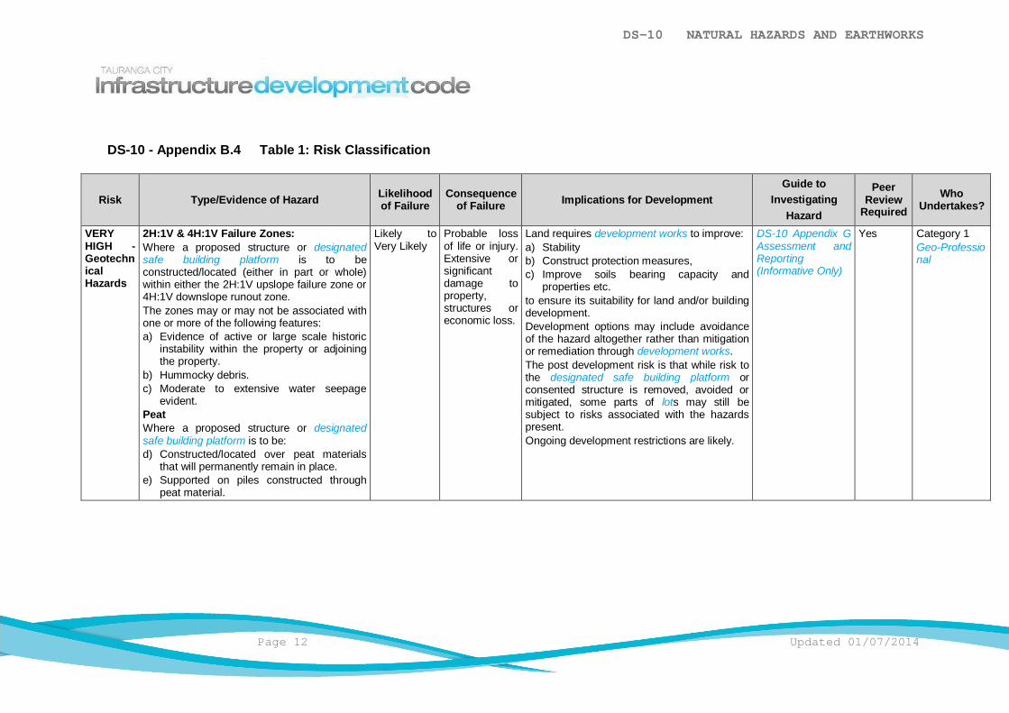
DS-10 NATURAL HAZARDS AND EARTHWORKS
Page 12 Updated 01/07/2014
DS-10 - Appendix B.4 Table 1: Risk Classification
Risk Type/Evidence of Hazard Likelihoodof Failure
Consequenceof Failure Implications for Development
Guide toInvestigating
Hazard
PeerReview
RequiredWho
Undertakes?
VERYHIGH -GeotechnicalHazards
2H:1V & 4H:1V Failure Zones:Where a proposed structure or designatedsafe building platform is to beconstructed/located (either in part or whole)within either the 2H:1V upslope failure zone or4H:1V downslope runout zone.The zones may or may not be associated withone or more of the following features:a) Evidence of active or large scale historic
instability within the property or adjoiningthe property.
b) Hummocky debris.c) Moderate to extensive water seepage
evident.PeatWhere a proposed structure or designatedsafe building platform is to be:d) Constructed/located over peat materials
that will permanently remain in place.e) Supported on piles constructed through
peat material.
Likely toVery Likely
Probable lossof life or injury.Extensive orsignificantdamage toproperty,structures oreconomic loss.
Land requires development works to improve:a) Stabilityb) Construct protection measures,c) Improve soils bearing capacity and
properties etc.to ensure its suitability for land and/or buildingdevelopment.Development options may include avoidanceof the hazard altogether rather than mitigationor remediation through development works.The post development risk is that while risk tothe designated safe building platform orconsented structure is removed, avoided ormitigated, some parts of lots may still besubject to risks associated with the hazardspresent.Ongoing development restrictions are likely.
DS-10 Appendix GAssessment andReporting(Informative Only)
Yes Category 1Geo-Professional

DS-10 NATURAL HAZARDS AND EARTHWORKS
Page 13 Updated 01/07/2014
Risk Type/Evidence of Hazard Likelihoodof Failure
Consequenceof Failure Implications for Development
Guide toInvestigating
Hazard
PeerReview
RequiredWho
Undertakes?
HIGH -GeotechnicalHazards
2H:1V & 3H:1V Upslope Failure Zones:Where a proposed structure or designatedsafe building platform is to beconstructed/located (either in part or whole) inthe zone between the 2H:1V and 3H:1Vupslope failure zones and one or more of thefollowing features is present:a) Clearly or poorly defined headscarpb) Evidence of historic instability (instability
may occur during and after extremeclimatic conditions and may extend beyondthe site boundaries).
c) Possible hummocky debris.d) Little to moderate evidence of water
seepage.Geological Features (Combinations)Moderately sloping land (15o<x<20o) locatedoutside of the failure zones (upslope anddownslope) that possess evidence of active orhistoric instability, landslip or face failureexhibited.Instability may occur within the propertyboundary or extend where located on anadjacent property, the effects of that instabilityare likely to affect the proposeddevelopment/proposed designated safebuilding platform.Moderate to excessive water seepage evident,hummocky debris.PeatConstructed/located on ground where theunderlying peat has been completely removedbut where this is underlain by othercompressible soils.Other
Unlikely toLikely
Possible lossof life or injury.Significant tomoderatedamage toproperty,structures oreconomic losspossible.
Land requires development works to improve:a) Stabilityb) Construct protection measures,c) Improve soils bearing capacity and
properties etc.to ensure its suitability for land and/or buildingdevelopment.Development options may include avoidanceof the hazard altogether rather than mitigationor remediation through development works.The post development risk is that while risk tothe designated safe building platform orconsented structure is removed, avoided ormitigated, some parts of lot may still be subjectto risks associated with the hazards present.Ongoing development restrictions are likely.
DS-10 Appendix GAssessment andReporting(Informative Only)
Discretionary
Category 1Geo-Professional
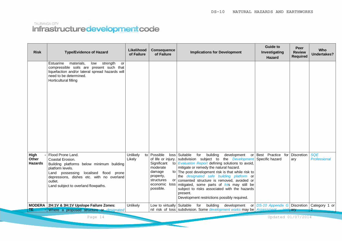
DS-10 NATURAL HAZARDS AND EARTHWORKS
Page 14 Updated 01/07/2014
Risk Type/Evidence of Hazard Likelihoodof Failure
Consequenceof Failure Implications for Development
Guide toInvestigating
Hazard
PeerReview
RequiredWho
Undertakes?
Estuarine materials, low strength orcompressible soils are present such thatliquefaction and/or lateral spread hazards willneed to be determined.Horticultural filling
High -OtherHazards
Flood Prone Land.Coastal Erosion.Building platforms below minimum buildingplatform levels.Land possessing localised flood pronedepressions, dishes etc. with no overlandoutlet.Land subject to overland flowpaths.
Unlikely toLikely
Possible lossof life or injury.Significant tomoderatedamage toproperty,structures oreconomic losspossible.
Suitable for building development orsubdivision subject to the DevelopmentEvaluation Report defining solutions to avoid,mitigate or remedy the natural hazard.The post development risk is that while risk tothe designated safe building platform orconsented structure is removed, avoided ormitigated, some parts of lots may still besubject to risks associated with the hazardspresent.Development restrictions possibly required.
Best Practice forSpecific hazard
Discretionary
SQEProfessional
MODERATE -
2H:1V & 3H:1V Upslope Failure Zones:Where a proposed structure or designated
Unlikely Low to virtuallynil risk of loss
Suitable for building development orsubdivision. Some development works may be
DS-10 Appendix GAssessment and
Discretionary
Category 1 or2

DS-10 NATURAL HAZARDS AND EARTHWORKS
Page 15 Updated 01/07/2014
Risk Type/Evidence of Hazard Likelihoodof Failure
Consequenceof Failure Implications for Development
Guide toInvestigating
Hazard
PeerReview
RequiredWho
Undertakes?
GeotechnicalHazards
safe building platform is to beconstructed/located (either in part or whole) inthe zone between the 2H:1V and 3H:1Vupslope failure zones with no othergeomorphic features present.PeatWhere a proposed structure or designatedsafe building platform is to beconstructed/located on ground where theunderlying peat material has been completelyremoved and the peat materials are locatedover competent soils with minimal likelihood ofsettlement occurring.OtherSpecific design of foundations where thethickness of compressible soils below thefoundation are 4m or greater. (Excludes peator materials listed in “Other” in the High Riskcategory).Little or no evidence of soil creep or instability.Instability may occur if development does nothave due regard for the site conditions.Stormwater disposal by way of soakage isproposed within areas defined as "SpecificDesign" and is located within 100m of a relicslip or 2H:1V upslope failure zone.
of life or injury.Moderatedamage toproperty andstructures oreconomic loss
required to improve stability or bearingcapacity.Engineering practices suitable to hillsideconstruction required.The post development risk is generally nohigher than normally accepted.Risk to designated building platforms orstructures removed.Development restrictions unlikely.
Reporting(Informative Only)
Geo-Professional
MODERATE –OtherHazards
Off-site effects created by urban intensification Unlikely Localisedflooding fromproperty toanother. Minordamage oreconomic loss.
Suitable for building development orsubdivision subject to the DevelopmentEvaluation Report defining solutions to avoid,mitigate or remedy the natural hazard.The post development risk is that some partsof completed lots may still be subject to risksassociated with present hazards but thatadjoining property has risks mitigated.Risk to designated building platforms or
Best Practice forSpecific hazard
Discretionary
SQEProfessional

DS-10 NATURAL HAZARDS AND EARTHWORKS
Page 16 Updated 01/07/2014
Risk Type/Evidence of Hazard Likelihoodof Failure
Consequenceof Failure Implications for Development
Guide toInvestigating
Hazard
PeerReview
RequiredWho
Undertakes?
structures removed.Development restrictions unlikely.
LOW -GeotechnicalHazards
Building platforms located clear of 2H:1Vupslope failure zone, 3H:1V upslope failurezone and 4H:1V downslope runout zones.No evidence of instability observed.Instability not expected unless major sitechanges occur and development does nottake issues into account.Gently sloping land (less than 15o)Specific design of foundations where thethickness of compressible soils below thefoundation are less than 4m. (Excludes peat ormaterials listed in "Other" in the High Riskcategory).Stormwater disposal by way of soakage isproposed within the areas defined as "SpecificDesign" and is located outside of 100m of arelic slip or 2H:1V upslope failure zone.
HighlyUnlikely
No loss of lifeor injury. Minordamage,limited to siteunless majordevelopmentoccurs or loweconomic loss.
Suitable for building development orsubdivision subject to the developmentdefining solutions to avoid, mitigate or remedythe natural hazard.Risk to designated building platforms orstructures removed.No development restrictions needed.
DS-10 Appendix GAssessment andReporting(Informative Only)
Discretionary
Category 1, 2 or3Geo-Professional or SQEProfessional
VERYLOW -GeotechnicalHazards
Typically shallow soil cover with flat to gentlysloping topography.
Nil Virtually nil ornil
Best Practice forSpecific hazard
Discretionary
SQEProfessional

DS-10 NATURAL HAZARDS AND EARTHWORKS
Updated 01/07/2014 Page 17
DS-10 - Appendix CGeo-Professional Accreditation System
DS-10 - Appendix C.1 General
Site investigation and risk assessment of geotechnical hazards in Tauranga City requireconsiderable geotechnical skills, experience and judgement. The nature of many of thesoils and landforms in Tauranga City is considered by experts as being very complexand difficult to assess how soils and landform profiles will perform in normal and extremeconditions.
To ensure the risks associated with complex geotechnical hazards are appropriatelymanaged, when undertaking building or land development, Council maintains a registerof Accredited Geo-Professionals.
This Geo-Professionals register is located on the Tauranga City Council's website.
The register provides for levels of expertise based on the complexity of the landform,refer to DS-10 Appendix B Landform Classification System, matched to an AccreditedGeo-Professional whose relevant qualifications, training and experience in the TaurangaCity environment along with appropriate peer support will ensure a robust managementof the risks associated with geotechnical hazards.
Only professionals who are accredited Geo-Professionals are approved to compile theparts of the Development Evaluation Report and Development Completion Reportrelating to geotechnical hazards or undertake the role of the Geo-Professional within theTauranga City area.
DS-10 - Appendix C.2 Geo-Professional
Refer to GEN-4 Definitions for definition of a Geo-Professional.
DS-10 - Appendix C.3 Three Tier Geo-Professional Accreditation System
The Council maintains a 3 tier register of Accredited Geo-Professionals.
a) The 3 tiers are:i) Category 1 Geo-Professional: Chartered Professional Engineer or Engineering
Geologist who is acknowledged by the Accreditation Panel as possessing theappropriate qualifications, skills and relevant experience in Tauranga City toprovide advice on all geotechnical issues found within Council’s area. Thiscategory may also include professionals of high national or internationalstanding who, despite not having extensive local experience or having beinginterviewed by the Accreditation Panel, Council considers to have sufficienttechnical ability to provide advice on specific ground conditions.

DS-10 NATURAL HAZARDS AND EARTHWORKS
Page 18 Updated 01/07/2014
ii) Category 2 Geo-Professional: A Chartered Professional Engineer orEngineering Geologist who is acknowledged by the Accreditation Panel aspossessing the appropriate qualifications, skills and relevant experience inTauranga City to provide advice on a limited number of less complexgeotechnical issues found in the Council area.
iii) Category 3 Geo-Professional: A Chartered Professional Engineer or anEngineering Geologist with an appropriate level of supervised work experiencein a related field. (Typically those professionally qualified and practisingGeo-Professionals or Engineering Geologists not listed on Tauranga CityCouncil’s Register.)
b) Admittance to either Category 1 or Category 2 (for either a Chartered ProfessionalEngineer or an Engineering Geologist) status on the register is by way of interviewby an independent panel of specialists (Accreditation Panel) convened by TaurangaCity Council.
c) Accreditation on the Register is for a period of 5 years. At completion of the 5 yearperiod the practitioner is required to be re-interviewed by the Accreditation Panel.
d) An application fee is payable by the applicant for the accreditation process.
DS-10 - Appendix C.4 Landforms Outside of Level of Accreditation
A Geo-Professional may undertake work in a category of landform one step above theircurrent classification. To do this the Geo-Professional shall engage a Category 1Geo-Professional to mentor and peer review their investigation approach, practices,testing and Development Evaluation Report and Development Completion Report.
(This provides the Geo-Professional a mechanism to develop professionally withguidance and demonstrate that they are becoming experienced enough through theongoing mentoring and coaching to be accredited to the next level of expertise.)
The following outlines this process:
a) Prior to commencing any site investigation or research the Geo-Professionalengages a Category 1 Geo-Professional to act as mentor and peer reviewer. Thementor discusses the approach proposed to be used by the Geo-Professional for theinvestigation and comes to an agreement with the Geo-Professional on the proposedapproach for the subject site. The site investigation is then undertaken in accordancewith the agreed approach. Regular communication between the two professionals isundertaken during the investigation and while defining the geological model for thesite, to ensure professional coaching occurs about key findings, assumptions andrecommendations.
b) The completed Geotechnical Assessment Report is then peer reviewed by thementor prior to submission to Council, who shall confirm the findings of the report asbeing appropriate and able to be relied upon by Council.
c) The cost for the peer review shall be met by the Consent Holder.

DS-10 NATURAL HAZARDS AND EARTHWORKS
Updated 01/07/2014 Page 19
d) In some circumstances the Geo-Professional may seek approval from Council toengage an appropriately qualified and experienced person who is not on the registerof Accredited Geo-Professionals to act as mentor and peer reviewer. Such anapplication shall be made in writing to the Council stating clearly the qualificationsand experience of the proposed reviewer. It should be noted that approval will begiven only in exceptional circumstances.

DS-10 NATURAL HAZARDS AND EARTHWORKS
Page 20 Updated 01/07/2014
DS-10 - Appendix DSuitably Qualified and Experienced Professional
DS-10 - Appendix D.1 General
Where a development is proposed for a site that is subject to other hazards a SQEProfessional shall be engaged to investigate, define the hazards/risk and formulatesolutions to ensure the risks associated with the hazard are avoided, remedied ormitigated and the designated safe building platform certified as meeting the performancecriteria above.
DS-10 - Appendix D.2 Suitably Qualified and Experienced Professional (SQEProfessional)
Refer to GEN-4 Definitions for definition of a suitably qualified and experiencedprofessional.
DS-10 - Appendix D.3 Role and Responsibilities of SQE Professional
See GEN-4 Definitions for the role and responsibilities of a suitably qualified andexperienced professional.

DS-10 NATURAL HAZARDS AND EARTHWORKS
Updated 01/07/2014 Page 21
DS-10 - Appendix EAccredited Geo-Professionals
DS-10 - Appendix E.1 Listing
Category 1 Geo-Professionals
Please refer to the Accredited Geo-Professionals List on the Tauranga CityCouncil's web-site.

DS-10 NATURAL HAZARDS AND EARTHWORKS
Page 22 Updated 01/07/2014
DS-10 - Appendix FPeer Review Requirements
DS-10 - Appendix F.1 General
Refer to:
a) QA-2 Appendix A.1 Requirement.
b) QA-2 Appendix A.2 Peer Review Procedures.c) QA-2 Appendix A.3 External Expert Advice.d) QA-2 Appendix A.4 Peer Review Guidelines (Informative).

DS-10 NATURAL HAZARDS AND EARTHWORKS
Updated 01/07/2014 Page 23
DS-10 - Appendix GAssessment and Reporting (Informative Only)
DS-10 - Appendix G.1 General
The assessment of landforms shall utilise the following principals and may besupplemented by the expert opinion stated in the documents noted in DS-10 APX AAssociated Standards:
a) All earthworks for a development shall:
i) Comply with the design criteria for completed landforms.
ii) Take the reduction of overland flow velocity and the concentration of overlandflow into account for the completed landform geometry and gradients.
iii) Provide for the permanent management of overland flow across landforms(contour drains, cut-off drains, formalised overland flowpaths not formingaccessways etc).
iv) Provide for the construction of man-made structures to create safe landformsand designed building platforms.
v) Where necessary provide for the installation of debris protection devices.
vi) Define the earth fill and subgrade construction standards, define testingfrequency, volumes and outline methods of testing to be used.
b) Observation, quality assurance and review of the earthworks design during theconstruction phase are covered in CS-3 Earthworks.
Engineering appraisal and design are required:
i) Prior to detailed planning, which may involve some form of subsurfaceinvestigation.
ii) During the review of and advice on design concepts.
iii) During construction to ensure the adequacy of the bulk filling and theexecution of the earthworks design.
c) Development Evaluation Reports and Geotechnical Completion Reports relating toCategory 1 and 2 landforms shall:
i) Be subject to a level of quality control appropriate to the complexity of theproject. This extends to an independent review within the company preparingthe report of the technical areas, key assumptions of the report, investigationfindings, adopted soils model, parameters and final conclusions opinions.
ii) Presence of and influence on the development from existing geomorphicfeatures.
iii) Assessment of historic landform stability and landform processes.
iv) Other engineering issues influencing the proposed development such as butnot restricted to, seismic stability, liquefaction, shrink/swell effects, foundationrequirements, limitations on surface water flow etc.
DS-10 NATURAL HAZARDS AND EARTHWORKS
Page 24 Updated 01/07/2014
v) In undertaking the assessment, the expertise of both a Geo-Professional andengineering geologist may be required to ensure a full understanding of thesite is gained.
DS-10 - Appendix G.2 Balancing Landform Choices
The final choice of landform is dependent on many factors, which may be specific to thedevelopment. These include the:
a) Relationship with surrounding landscapes.
b) Natural drainage patterns.
c) Size of the development.
d) Proposed and existing roading patterns.
e) Preservation of natural features.
f) Enhancement of natural features where compromised by fragmentation or reductiondue to the development.
g) Stability of the land.
h) Function and purpose of the development.
i) Potential for flooding, erosion and other natural events.
The order of importance of these factors will vary from project to project.
The final choice of landform must represent the most desirable compromise between thedevelopment requirements, the preservation of natural features including the existing soilprofile, and the natural quality of the landscape. Preservation aspects include retainingnatural watercourses, and excluding any development from natural gullies (refer to theDistrict Plan).
DS-10 - Appendix G.3 Reducing Waste
When designing the development, consider ways in which waste can be reduced.
a) Design to reduce waste during construction e.g. minimise earthworks, reuseexcavated material elsewhere.
b) Use materials with a high recycled content e.g. recycled concrete subbase.Proposed recycled materials will need approval from the Council to ensure thatenvironmental contamination does not occur.
Refer to the Resource Efficiency in the Building and Related Industries (REBRI) websitefor guidelines on incorporating waste reduction in your project www.rebri.org.nz.
DS-10 - Appendix G.4 Existing Landforms
Study the general nature and shape of the ground and take particular note of:
a) The geological nature and distribution of soils and rock.
DS-10 NATURAL HAZARDS AND EARTHWORKS
Updated 01/07/2014 Page 25
b) Existing and proposed drainage conditions and the likely effects on groundwater.
c) The previous history of ground movements in similar soils in the area.
d) Where earthworks are involved, the performance of comparable cuts and fills (if any)in adjacent areas.
Air photography and other sources of information that should be reviewed andincorporated into any slope stability assessment.
DS-10 - Appendix G.5 Suitability
The choice of a suitable landform is dependent on many factors that may be specific to aparticular site. Avoid unnecessary earthworks, aim to protect original soils and drainagepatterns and to minimise disturbance, compaction, earthworks and importation of topsoil,although earthworks may be justified in the following circumstances to:
a) Minimise the risk of property damage through ground movement in the form of rockfall, slips, subsidence, creep, erosion or settlement.
b) Minimise the risk of property damage through flooding, or surface water run-off.
c) Lessen tunnel gully erosion within hillside developments.
d) Develop a more desirable roading pattern with improved accessibility to and withinthe site, and to create a better sense of orientation and identity for the area as awhole.
e) Increase the efficiency of overall land use, including the quality of individual sites andamenity areas around buildings, the economics of providing engineering servicesand the standard of roading and on-site vehicular access.
f) Create, where needed, suitably graded areas for playing fields and other communityfacilities.
g) Enhance the general environmental character of the area by softening the landscapeor by artificially creating or emphasizing landforms of visual significance, particularlyon flat sites or on areas devoid of landscape features.
DS-10 - Appendix G.6 Seismic Considerations
Consider the seismic effects on earthfills, slopes and liquefiable ground, and take theseinto account in the design and construction of any development.
DS-10 - Appendix G.7 Peat
Ensure the geotechnical design in peat areas will achieve the infrastructure design liferequired by all other parts of the IDC. Preserve the flow of groundwater through the peatat pre-development levels.

DS-10 NATURAL HAZARDS AND EARTHWORKS
Page 26 Updated 01/07/2014
DS-10 - Appendix G.8 Table 2: Description of Geomorphological Zones and Assessment Guidelines
Risk Category Assessment Guidelines
Very High and High RiskRequires extensive and detailedengineering geological and geotechnicalassessment. Intensive investigation maybe required and development may not beeconomically feasible. Boreholes todetermine geology present will berequired.Assessment of site required by bothengineering geologist andGeo-Professionals.
a) Initial assessment to be carried out by Category 1 Geo-Professional (Engineering Geologist and Geo-Professional)b) Examination, on foot, of the surface of the site and the surrounding ground, with the assistance of existing topographical mapsc) Examination of available aerial photographs of the area (include selection from early to present time)d) Assessment of available geological data (IGNS and other maps, publications, university theses and any other published or
unpublished data)e) Review of relevant files and other historical recordsf) Check with local residence and other sources for evidence of past instability, particularly during periods of heavy rainfallg) Prepare preliminary report including geomorphological map of site, detailed cross sections showing site stratigraphy, preliminary
conclusions on site characteristics and recommendations for additional investigation, mapping and monitoring. Report to includespecific reference to all aerial photographs and other sources of information used for the study
h) Geomorphological assessment to provide conclusion on characteristics of any landslide present and the history of movement(historical or current)
i) If landslide with recent movement effects the site, further topographical surveys, ground investigations and stability analysis will berequired to demonstrate that the site can be made adequately safe by remedial works
j) Undertake investigation to determine the nature and distribution of the soils that may be prone to slip and develop engineeringgeology site model
k) Measure groundwater pressures in the soils strata and evaluate the transient pressures that may develop ender extreme rainfallconditions
l) Produce engineering geological report with details of mass movement features and other ground failure hazardsm) Carry out geotechnical evaluation, using Category 1 Engineer and including further sampling, laboratory testing, assessment of
ground properties, groundwater monitoring, etc. If strength assessment has been made by reference to test data from the othersites, provide detailed rationale for the use of such data
n) Undertake slope stability evaluation using approved methodso) Make recommendations for use of site and provide design for remedial measures if appropriate
Moderate RiskSome sites may require detailedengineering geological and geotechnicalassessmentVisual assessment. Hand and possibledrill investigation methods.
a) Assessment to be carried out by Category 1 or 2 Geo-Professional (Geologist/geomorphologist or Geo-Professional)b) Examination, on foot, of the surface of the site and the surrounding ground, with the assistance of existing topographical mapsc) Examination of available aerial photographs of the area (include selection from early to present time)d) Assessment of available geological data (IGNS and other maps, publications, university theses and any other published or
unpublished data)e) Review of council files and other historical recordsf) Check with local residence and other sources for evidence of past instability, particularly during periods of heavy rainfallg) If absence of recent or current landslide activity is confirmed, prepare report confirming this with appropriate documentation (map

DS-10 NATURAL HAZARDS AND EARTHWORKS
Page 27 Updated 01/07/2014
and representative sections)h) If ground hazard identified, follow Steps 7 to 15 of Zone 1 procedures
Low RiskDoes not require engineering geologicaland geotechnical assessment
a) Site to be inspected by competent Category 2 person (Registered Engineer or Geologist with equivalent experience)b) Provide written confirmation of inspection and judgement that there is no landslide hazard at the site
Very Low RiskNo requirement for Engineering Geologyor Geo-Professional expertise
a) Site to be inspected by competent category 3 person

DESIGN STANDARDDS-11 ROAD ZONE OCCUPANCY
TABLE OF CONTENTS
DS-11.1 General ............................................................................................................1
DS-11.2 Minimum Requirements ....................................................................................1
DS-11.3 Regional Council Requirements .......................................................................1
DS-11.4 Corridor Manager .............................................................................................2
DS-11.5 Utility Operator .................................................................................................2
DS-11.6 Responsibility for Suppliers, Agents and Contractors .......................................2
DS-11.7 The Road Zone Occupancy Process ................................................................2
DS-11.8 Location of Utilities ...........................................................................................7
DS-11.9 Design, Construction and Materials ..................................................................7

DS-11 ROAD ZONE OCCUPANCY
Updated 01/07/2014 Page 1
DS-11.1 General
The Road Zone is the width of land between lot boundaries.
It includes above and below ground utility service corridors or locations for:
a) Streetscape features such as ground surfacing, street furniture, trees etc.
b) Transportation features such as carriageways, vehicle crossings, signs etc.
c) Stormwater, wastewater and water supply features such as reticulation, connections,structures, fittings etc.
d) Public lighting features such as streetlights, decorative lighting etc.
e) Network utility features for power supply, telecommunications, gas reticulation, fittingsetc.
f) Other features such as boundary pegs and survey benchmarks.
g) Events and public gatherings.
The safety of the people working on and around these utilities, the safety of the generalpublic who use the Road Zone (for everyday use) and the protection of the utilitiesthemselves are of immense importance when undertaking any work within the Road Zone.
DS-11.2 Minimum Requirements
All work on the Road Zone shall comply with all reasonable conditions applied by theCorridor Manager. These consist of:
a) General Conditions – These are located in DS-11 APX B: General Conditions.
b) Local Conditions as applied to the Works Access Permit (WAP).
c) Special Conditions as applied to the Works Access Permit (WAP).
Where the IDC is silent on any issue, the National Code of Practice for Utilities Access to theTransport Corridors shall apply.
DS-11.3 Regional Council Requirements
For an outline of any Bay of Plenty Regional Council requirements refer to:
a) DS-2 Streetscape.
b) DS-4 Transportation Network.
c) DS-5 Stormwater.
d) DS-6 Wastewater.
e) DS-7 Water Supply.
f) DS-8 Public Lighting.
Refer to Bay of Plenty Regional Council for clarification for any potential Bay of PlentyRegional Council requirements for other network utilities.
DS-11 ROAD ZONE OCCUPANCY
Page 2 Updated 01/07/2014
DS-11.4 Corridor Manager
Refer to Corridor Manager definition for responsibilities. The Corridor Manager of the:
a) Local transportation network is the Council.
b) State Highway transportation network is the New Zealand Transport Agency (NZTA).
c) Rail network is Kiwirail.
Any work on a State Highway that may affect a Council managed Road Zone shall also benotified to Council.
Neither a) nor b) have jurisdiction over the rail corridor. For work within the rail corridor, theapplicant shall apply to the Rail Corridor Manager.
DS-11.5 Utility Operator
Refer to Utility Operator definition for responsibilities.
The Utility Operator is the owner responsible for the operation and maintenance of eachutility i.e. the Utility Service Provider. The major Utility Operators for the Tauranga Area arenoted in DS-11 APX C: Utility Operators.
DS-11.6 Responsibility for Suppliers, Agents and Contractors
Each party is responsible, in respect of the IDC, for their actions and omissions of itsdelegates (agents, consultants, contractors and employees), except to the extent that anyAct provides otherwise.
DS-11.7 The Road Zone Occupancy Process
This process is designed to ensure that the relevant interests of all the parties areconsidered and that conditions are fair and reasonable.
DS-11.7.1 Outline of the Application Process
The following outlines the application process:
a) DS-11.7.2 Preliminary Notification.
b) DS-11.7.3 Corridor Access Request (CAR).
c) DS-11.7.4 Approval Process and Setting of Reasonable Conditions.
d) DS-11.7.5 Works Access Permit (WAP).
e) Commencement/Completion of works.
f) Monitoring of works / reinstatement.
g) The issue of Works Completion Notice.

DS-11 ROAD ZONE OCCUPANCY
Updated 01/07/2014 Page 3
DS-11.7.2 Preliminary Notification
The following shall apply:
a) When undertaking works that are neither automatically permitted nor emergencyworks in the corridor, Utility Operators shall provide the Corridor Manager preliminarynotice of those works prior to lodging for any CAR where requested.
b) The Corridor Manager shall meet with the relevant Utility Operator to discusscoordination of the proposed works and jointly identify any issues that are likely toaffect the works or the CAR.
c) The following information shall be submitted by the Utility Operator with thepreliminary notification where requested by the Corridor Manager:
i) A preliminary plan indicating the scope and scale of the intended worksincluding depth and location of any proposed utility or structure and thepresence of any adjoining utilities and streetscape features.
ii) Any matters where there is a likely major impact on the public.iii) Key points of relevant meetings and public or other consultation to the Corridor
Manager.
iv) Details of when the work is scheduled (dates and time of day).
DS-11.7.3 Corridor Access Request (CAR)
Before construction can commence, the Utility Operator shall lodge a CAR. The UtilityOperator may delegate the responsibility of lodging the CAR. The CAR shall be lodgedusing the online CAR Form. This can be found athttp://www.tauranga.govt.nz/council-documents-reports/councils-regulatory-documents/infrastructure-development-code/corridor-access-request.aspx
Where applicable, the following information shall be supplied with the CAR:
a) A site specific traffic management plan.
b) A plan indicating intended scope and scale of the intended works, including depthand route of any proposed utility and the location of any adjoining utilities andstreetscape features.
c) Proof of all permits, permissions, demonstrating compliance with all consentconditions, City Plan provisions and Acts, where these apply. It is the UtilityOperator’s responsibility to ensure that any necessary Resource Consents, buildingconsents or encroachment type licenses are obtained.
d) Details of when the work is scheduled (dates and time of day).e) Proposed location of any chambers or above ground structures.
f) The type of Permit being applied for. Refer DS-11.7.3.1 Types of Permit.
DS-11.7.3.1 Types of Permit
When lodging a CAR, the Utility Operator shall specify the type of permit beingapplied for. The permit types are:
DS-11 ROAD ZONE OCCUPANCY
Page 4 Updated 01/07/2014
a) Non-Utility Operator Works - In general these works create very low risk to RoadZone users and infrastructure and includes:
i) Minor scaffolding works associated with small scale renovation or buildingmaintenance
ii) Shop front fit outs / repairs / replacements
iii) Crane operations up to 4hr duration to lift materials etc into or ontobuildings and / or sites.
iv) Building cleaning operations up to 4hrs.
b) Minor Works - In general these works create low risk to Road Zone users andinfrastructure and includes:
i) Up to 2 calendar days duration.
ii) Simple service connections.
iii) Up to 20m affected length.
iv) Minor work associated with Utilities.
v) Overhead veranda works.
vi) Berm work only.
vii) Larger scale scaffolding projects occupying the Road Zone.
viii) Excludes road crossings.
ix) Multiple sites for Minor Works may be considered under a singleapplication at the discretion of the Corridor Manager
c) Standard Works - In general these works create moderate risk to other RoadZone users and infrastructure and include:
i) More than 2 and up to 30 calendar days duration.
ii) More than 20m and up to 250m affected length.iii) Any road crossing or intrusion whether open trenched or trenchless.
iv) Moderate inspection requirement.
d) Comprehensive Works - In general these works create high risk to other RoadZone users and infrastructure and include:
i) Duration > 30 calendar days occupancy.
ii) Over 250m affected length.
iii) High inspection requirement.iv) High level of effect on Level 2 Roads.
v) Restricted property access.
e) Maintenance Works - In general terms these are works agreed to by theCorridor Manager as likely to be completed under a maintenance contract thatincludes most of the permit requirements and forward works programmes arealso submitted.
i) Repair to an existing service or surface
ii) Excludes new works within the Road Zone
DS-11 ROAD ZONE OCCUPANCY
Updated 01/07/2014 Page 5
f) Emergency Works - An unexpected repair of a service to reduce the risk ofsignificant or immanent threat of physical damage or destruction to Road Zoneusers, infrastructure, property and includes:
i) Duration no longer than 24hours.
ii) Rectification of a dangerous situation including support requested by anemergency service.
g) Events - In general this includes any public activity, gathering, sporting event,show or parade undertaken by any party for any period of time that has thepotential to cause risk to Road Zone users and infrastructure, whether the Eventis, or is not, located within the Road Zone.
Where it is not clear which of the permit types an activity falls within, the CorridorManager shall decide the appropriate permit type.
DS-11.7.3.2 Permit Fees
Council may charge appropriate fees for cost recovery relating to permit processingand works inspections. All associated fees shall be payable by the applicant. Wherethe applicant defaults, the Utility Operator relevant to the permit will be charged byCouncil.
The fees are non-refundable deposits. Where applicable, Council may chargereasonable additional fees for actual time and cost in excess of the expectedrequirements of the permit.
Fees shall be set in Council’s Fees and Charges Manual.
DS-11.7.4 Approval Process and Setting of Reasonable Conditions
The following shall apply:
a) The Corridor Manager shall consider the CAR for approval and set appropriateconditions to accompany a Works Access Permit (WAP).
b) The Corridor Manager may also consider Local and Special Conditions for the(WAP). These may include:
i) Unique topographical or geotechnical conditions.
ii) Particular physical characteristics of the corridor.iii) Unique IDC, City Plan or Regional Plan requirements.
iv) Unique Building Act requirements.
v) Unique land use policies e.g. encroachment licence requirements.
vi) Pollution Control.
vii) Special dates and events.
DS-11.7.5 Works Access Permit (WAP)
The following shall apply:

DS-11 ROAD ZONE OCCUPANCY
Page 6 Updated 01/07/2014
a) The Utility Operator or Contractor shall keep a copy of the WAP on site at all timeswhile working within the corridor.
b) An additional CAR or WAP may be required on a particular work site for each of thefollowing situations:i) When it involves more than one road.
ii) When it involves more than one Utility not covered by an existing CAR orWAP.
iii) The location of work site moves to a position not described on the CAR orWAP.
iv) The work has not been completed within the WAP expiry date.
c) The Corridor Manager may request a Utility Operator install additional ducts foreither the Utility Operators or the Corridor Managers use. The additional ducts andtheir installation shall be at the expense of the party who will own the ducts.
DS-11.7.6 Commencement/Completion of Works
The works shall not commence until the WAP has been received and the CorridorManager has been given the required notice of intent to commence works. Where notedon the WAP, the Utility Operator shall contact the affected parties in the statedtimeframes.
DS-11.7.7 Monitoring of Works / Reinstatement
The Corridor Manager will monitor the works with particular attention to thereinstatement of the site to an acceptable condition.
DS-11.7.8 Works Completion Notice (WCN)
The following shall apply:
Upon completion of the works, the Utility Operator shall lodge a Works CompletionNotice (WCN) with the Corridor Manager. The WCN shall be lodged using the WCNForm that will be provided to the applicant when a WAP has been approved.
The WCN shall include the following as appropriate (unless otherwise agreed):
a) Confirmation that As-built information has been supplied to the Utility Operator who'sservice is affected by the works. For Council utilities this shall be presented as notedin QA-5 As-Built Information.
b) Quality assurance records or certification.
c) A written statement confirming that the completed works fully comply with theconditions imposed by the WAP signed by a person authorised to bind the UtilityOperator.
d) Details of any outstanding work that the Utility Operator has agreed to complete e.g.pavement surfacing, road marking.

DS-11 ROAD ZONE OCCUPANCY
Updated 01/07/2014 Page 7
DS-11.8 Location of Utilities
All utilities shall be located, where possible, in the location/s shown on the StandardDrawings.
Where the standard location is not possible, a new location shall be approved between theUtility Operator and the Corridor Manager. Acceptance of this new location will be includedin the approval of the Works Access Permit (WAP).
DS-11.9 Design, Construction and Materials
All design, construction and materials shall be as per best practice guidelines, codes ofpractice, standards or other relevant literature produced or governed by each UtilityOperator.
For all Council utilities the IDC and any references within it apply.
DS-11 ROAD ZONE OCCUPANCY
Page 8 Updated 01/07/2014
DS-11 - Appendix AAssociated Standards
DS-11 - Appendix A.1 General
The latest revision or operative version of the following standards shall be used inconjunction with the IDC:
a) Council documentation:
i) City Plan.
ii) TCC Traffic Systems Design and Implementation Guidelines.
b) New Zealand/Australian/British Standards:
i) National Code of Practice for Utilities Access to the Transport Corridors.
ii) NZTA CoPTTM Code of Practice for Temporary Traffic Management andLocal Supplement.
c) Other reference material:
i) Resource Management Act 1991.
ii) New Zealand Building Act.
iii) New Zealand Health and Safety in Employment Act 1992.
iv) Utilities Access Act 2010.
Note: All works shall be in accordance with the relevant Utility Operators standards orliterature where possible.
DS-11 ROAD ZONE OCCUPANCY
Updated 01/07/2014 Page 9
DS-11 - Appendix BGeneral Conditions
DS-11 - Appendix B.1 General Conditions for Road Zone Occupancy
The Utility Operator shall:
i) Carry out all Works in the Road Corridor in compliance with the governinglegislation for the related industry.
ii) Carry out all Works in the Road Corridor in compliance with the requirementsset out in the Local and Special Conditions.
iii) Obtain all the necessary consents, approvals and permits from the relevantstatutory and regulatory authorities at their own cost.
iv) Install assets/infrastructure in the location shown on the approved plans,unless subsequent written approval is received from the Corridor Manager toalter the location or any other element of the works.
v) Provide a proposed Traffic Management Plan for approval with theirapplication.
vi) Provide, when requested, a full description of the construction methodology,quality assurance, reinstatement, resurfacing and compaction and agree thiswith the Corridor Manager prior to work commencing.
vii) Ensure payment of all required fees and charges for processing of this noticeand for the monitoring and auditing of the works.
viii) Provide the Corridor Manager with written notice 2 working days beforecommencement of work on site.
ix) Keep a full copy of the Works Access Permit and Local/Special Conditions onsite at all times during the Works.
x) Keep plans of the installed work and make them available to Corridor Manageron request.
xi) Ensure that the work is carried out under the control of a warranted supervisoras required by the NZTA CoPTTM Code of Practice for Temporary TrafficManagement and/or Local Supplement and ensure that there are sufficientpeople on site specifically to control the flow of traffic through the site inaccordance with the Traffic Management Plan.
xii) Comply with instructions from an officer of the New Zealand Police TrafficSafety Branch or a duly authorised agent of the Corridor Manager in respect oftraffic management and safety.
xiii) Control the surface water channels so as to cause minimal interference toexisting flows and fully restore the surface water channels at the completion ofthe works.
xiv) Stop work as necessary to meet the requirements of Section 10 of the HistoricPlaces Act 1993.
xv) Make the Works available at all times for inspection by any personrepresenting the Corridor Manager.

DS-11 ROAD ZONE OCCUPANCY
Page 10 Updated 01/07/2014
xvi) Restore to their original condition any surface or structure that was damagedor removed as a result of the Works.
xvii) Undertake remedial action on non-conforming work within the timeframe set bythe Corridor Manager, where reasonable and practicable.
xviii) Repair all damage as a result of the works, should the Corridor Managerdetermine these are necessary prior to the end of the Warranty period.
xix) Compensate the affected party for any damage or costs incurred due to thework or for costs resulting from the removal of abandoned installations,structures, components and equipment that belong to the Utility Operator.
xx) Notify the Corridor Manager of any maintenance work it proposes to undertakewithin the 2 Year Warranty period.
xxi) Complete Works in the Road Corridor in one continuous operation (workssuspended for over five days require the written permission of the CorridorManager).
xxii) Protect and maintain all Road Corridor signs, markers, signals, barriers andassociated marking and replace them to the appropriate industry standardwhere they have been damaged by the Works.
xxiii) Complete and submit a Works Completion Notice when the Works arecomplete.
a) Work, other than Emergency Works, must not take place on the Road Corridorduring and one day either side of a public holiday or public holiday weekend.
b) Work, other than Emergency Works, must not take place on the Road Corridorduring and one day prior to any major Event.
c) All Works must be performed within the hours of work specified on the Works AccessPermit unless written approval to alter this is given by the Corridor Manager.
d) All Works Access Permits will only remain valid for the time period specified on theWorks Access Permit unless written approval to extend this time is given by theCorridor Manager.
e) The 2 Year Warranty period commences from the date the Corridor Manager hasgiven written confirmation that the work is complete.
f) The Corridor Manager shall:
i) Manage all applications relating to corridor access in accordance with thetimeframes and processes in the National Code of Practice for Utilities Accessto the Transport Corridors.
ii) Not be liable for any costs, actions, demands, suits, damages andproceedings of any kind for any loss, damage or injury that may result from theworks that are undertaken by or on behalf of the Utility Operator.
g) The Corridor Manager may:
i) Include the requirement for the Utility Operator to provide a Contract Bond infavour of the Corridor Manager or the Contractor to provide a Contract Bond infavour of Utility Operator as a performance guarantee.
DS-11 ROAD ZONE OCCUPANCY
Updated 01/07/2014 Page 11
ii) Instruct the Utility Operator to stop work and leave the site (having made thesite safe) if the Works are not complying with the relevant Works AccessPermit including any plans, relevant conditions, permission requirements orspecifications contained in the documents listed in the Local and SpecialConditions.
iii) Arrange for remedial work to be done and recover the costs incurred from theUtility Operator, if the Utility Operator fails to take action within the agreedtimeframe.
iv) Assess the suitability of any action proposed by the Utility Operator during theWarranty Period and impose Reasonable Conditions that will maintain theintegrity of the Road assets.
h) In granting a Works Access Permit, no vested right is created.
i) Works Access Permits are not transferable without the written permission of theCorridor Manager.
j) In the absence of a written agreement from the Corridor Manager for an extension,All Works relating to the Works Access Permit shall be completed within thepermitted timeframe shown on the Works Access Permit. The Works Access Permitshall become invalid if the works do not conclude within the Permit timeframe.

DS-11 ROAD ZONE OCCUPANCY
Page 12 Updated 01/07/2014
DS-11 - Appendix CUtility Operators
DS-11 - Appendix C.1 Major Utility Operators within Tauranga City
Road Zone Occupancy - Utility Operators
Utility Type Company Address Contact PhonePower Powerco Level 2,
138 Maunganui RdPO Box 10166Mt Maunganui 3152
Planning Manager 07 928 6013
Telecommunication Telecom Exchange BuildingLevel 3, Hinemoa StRotorua
Senior Delivery Specialist 07 349 9252
FX Networks Level 2,41a Bath StreetparnellAuckland 1052
Project Manager 09 974 9315
TelstraClear(Downer EDI)
PO Box 340Tauranga 3140
Designer 029 927 7793
2degrees mobile 131 Khyber Pass RoadNewmarketAuckland
Lease and Property Manager 09 919 70460508 022 662
Ultrafast Fibre Ltd 114 Maui StreetTe RapaHamilton
Commercial Manager 07 850 3153
Council Fibre(Tga City Council)
91 Willow StreetPrivate Bag 12022Tauranga 3143
Network Administrator 07 577 7056
Natural Gas Electrix(Vector Ltd)
Unit 8,Totara Business ParkPO Box 944Mt Maunganui 3116
Distribution Coordinator 07 547 4932
Water Supply City Waters(Tga City Council)
91 Willow StPrivate Bag 12002Tauranga 3143
Water Supply Manager 07 577 7000
Wastewater /Stormwater
City Waters(Tga City Council)
91 Willow StPrivate Bag 12002Tauranga 3143
Drainage Services Manager 07 577 7000
Transportation /Streetscape
City Transportation(Tga City Council)
91 Willow StPrivate Bag 12002Tauranga 3143
Transportation OperationsManager
07 577 7000
Trees / Gardens City Parks(Tga City Council)
91 Willow StPrivate Bag 12002Tauranga 3143
Team Leader: City Parks 07 577 7000

Affected Parties
Postal Services New Zealand Post 65 Chapel StreetTauranga
Team Leader:Tauranga Mail Centre
07 577 1508
DX Mail 32 - 36 Gallagher DriveFranktonHamilton
Waikato/BOP RegionalManager
07 843 0763
Geodetic Systems Land InformationNZ
Cnr Victoria and Rostrevor StsPrivate Bag 3028Hamilton 3240
0800 665 463
City Development(Tga City Council)
91 Willow StreetPrivate Bag 12022Tauranga 3143
Asset Information Officer 07 577 7000
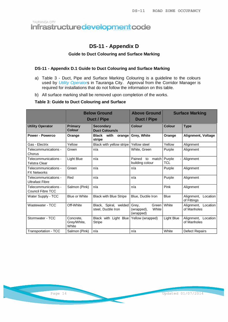
DS-11 ROAD ZONE OCCUPANCY
Page 14 Updated 01/07/2014
DS-11 - Appendix DGuide to Duct Colouring and Surface Marking
DS-11 - Appendix D.1 Guide to Duct Colouring and Surface Marking
a) Table 3 - Duct, Pipe and Surface Marking Colouring is a guideline to the coloursused by Utility Operators in Tauranga City. Approval from the Corridor Manager isrequired for installations that do not follow the information on this table.
b) All surface marking shall be removed upon completion of the works.
Table 3: Guide to Duct Colouring and Surface
Below GroundDuct / Pipe
Above GroundDuct / Pipe
Surface Marking
Utility Operator PrimaryColour
SecondaryDuct Colours/s
Colour Colour Type
Power - Powerco Orange Black with orangestripe
Grey, White Orange Alignment, Voltage
Gas - Electrix Yellow Black with yellow stripe Yellow steel Yellow AlignmentTelecommunications -Chorus
Green n/a White, Green Purple Alignment
Telecommunications -Telstra Clear
Light Blue n/a Pained to matchbuilding colour
Purple -TCL
Alignment
Telecommunications -FX Networks
Green n/a n/a Purple Alignment
Telecommunications -Ultrafast Fibre
Red n/a n/a Purple Alignment
Telecommunications -Council Fibre TCC
Salmon (Pink) n/a n/a Pink Alignment
Water Supply - TCC Blue or White Black with Blue Stripe Blue, Ductile Iron Blue Alignment, Locationof Fittings
Wastewater - TCC Off-White Black, Spiral, weldedsteel, Ductile Iron
Grey, Green(wrapped), White(wrapped)
White Alignment, Locationof Manholes
Stormwater - TCC Concrete,Grey/White,White
Black with Light BlueStripe
Yellow (wrapped) Light Blue Alignment, Locationof Manholes
Transportation - TCC Salmon (Pink) n/a n/a White Defect Repairs