design standards for streets and related facilities standards for streets and related facilities i....
TRANSCRIPT

SS-1
Design Standards for Streets and Related Facilities
I. Policy:
Street and related facilities within a land subdivision or within the City limits shall be developed and improved in accordance the City’s Standard Guide Manual for Construction and Development, supplements by the City Engineer and any revisions.
II. General:
Streets and related transportation facilities shall be designed by a professional engineer licensed in the State of Florida. The design shall meet the requirements as established in the Florida Department of Transportation Roadway Design Manual, Manual on Uniform Traffic Control Devices and this guide manual.
Residential roadways shall be designed to incorporate the latest traffic calming techniques and promote safe pedestrian and bicycle safety. The residential streets shall be designed with a target speed limit of 25 mph. Collector street shall be designed for a speed limit appropriate for the pavement section and intended use.
III. Continuation of Existing Streets:
The continuation of existing street networks is desired to promote connectivity and multi-way access into developments. Existing streets shall be continued at the same width and may be reduced to a narrower standard if permitted in this manual and subject to provision of the appropriate transitions between roadway widths.
IV Street Intersections:
Street intersections should be at right angles to maximize sight visibility. No street angle less than 60 degrees will be permitted unless required by extra ordinary conditions
V Street Jogs:
Street jogs with centerline offsets less than 125 feet shall not be permitted.

SS-2
VI. Specific Requirements: A. Clearing and Grubbing: All clearing and grubbing of the roadway and right of
way shall be done in accordance with the Florida Department of Transportation Standard Specifications. All deleterious material shall be removed from the right of way and properly disposed.
B. Right of Way - The minimum right of way for all roads will be based on the
classification of the road as determined by the City Engineer and the type of roadway section, stormwater management system, utilities, bike lanes, sidewalks, street trees or other amenities proposed to be utilized.
1. Residential Roadway 50' 2. Residential Collector 60' 3. Multi lane or divided facilities 80' C. Design Speed: Residential roadways shall be designed to facilitate the posting of a
25 mph speed limit to create a more pedestrian and bicycle friendly environment. All other roadway types shall be designed based on the character of the proposed use with design speeds ranging from 30 mph to 55 mph. The City Engineer shall have the final determination on the appropriate design speed at the time of design development.
D. Vertical Alignment : Street grades shall conform to the maximum extent possible
to the natural topography. Maximum grades are as follows: 1. Arterial Street 3% 2. Collector Street 4% 3. Residential Streets 8% 4. No streets shall be less than 0.36%
The Florida Department of Transportation Roadway Design Standards shall be used for the determination of the need for vertical curves for changes of grades based on roadway types.
E. Storm Drainage: All streets shall be designed to provide adequate stormwater
systems.
For multi phased projects a master stormwater design submittal and approval is required for all phases at the time of permitting for the first phase of development to assure compatibility between all phases.

SS-3
The Roadway level of service for flooding is as follows: 1. For the 5 year FDOT 1 hour storm, the hydraulic grade line of the
stormwater system must be one foot below the roadway edge of pavement. 2. There shall be no street flooding outside the curb and gutter area for the 25
year 24 hour storm. 3. The roadway shall remain passable with a maximum of 3 inches of water
depth in the travel lanes for the 100 year 24 hour storm. F. Underdrain: Underdrain shall be used only where absolutely necessary. When
underdrain is used, a water resistant base must also be used. The minimum separation between the bottom of the roadway base and the seasonal high water table is 1.0 feet for a water resistant base and 2 feet for limerock or similar material. If underdrain is used, the stormwater system shall include this base flow in the design of the piping, inlets and ponds. Clean outs shall be provided and marking wire used for future locates.
G. Street Curb and Gutter: Curb and gutter shall be installed on all arterial, collector
and residential streets unless approved in writing by the City Engineer. The type of curb and gutter used shall be based on various factors including but not limited to: design speed, roadway cross section type, need to limit access to property, clear zone protection for sidewalks, trees or other appurtenances in the right of way. The City Engineer has the final determination of the appropriateness of the type of curb and gutter proposed for a specific project.
H. Curb Line Radius: The minimum curb line radius for residential streets is 25 feet,
for commercial is 35 feet and for industrial areas is 40 feet. I. Minimum Pavement Widths: The minimum pavement widths are based on street
type and are as follows: Residential Roadways 22' pavement width or two
eleven feet travel lanes Alleys 16 feet pavement width Industrial, Collector and Arterial Roadways minimum of 12 feet travel
lanes J. Sidewalks: Sidewalks shall be constructed with 3000 psi at 28 days concrete with
no wire mesh. Materials and Methods shall conform to the latest edition of Florida Department of Transportation Standard Specifications for Road and Bridge Construction. The minimum thickness shall be six inches and the minimum width

SS-4
is five feet. All sidewalks and handicap ramps shall be designed to meet the ADA requirements in affect at the time of construction.
K. Driveways: Concrete driveways shall be constructed from the edge of
curb/pavement to the right of way line. Driveways shall be a minimum of six inches thick of 3000 psi concrete and shall be installed over a compacted base. No wire mesh is permitted in the right of way. The width, location and configuration of the driveway shall be based on the engineering judgement of the City Engineer. Factors considered include, but are limited to: proposed use, type of vehicles, location, sight configuration, location to a corner, median openings, volume of traffic on connecting roadway. Sewer laterals and water meters are not permitted to be under the driveway.
L. Street Markers: The design plans shall include a proposed signing and marking
plan. The plan shall contain the following minimum information:
Location and type of all stop bars, center line striping, edge striping, turn lane striping, arrows, school zone markings, bike lanes designations, gore area markings etc. As a general guideline, the City does not provide centerline striping on residential roads. Collector and higher classes of roadways are typically striped. All striping shall be thermoplastic and shall follow The Florida Department of Transportation Standard Specifications Section 711.
Stripping and signage of private amenity crossings such as bike lanes, golf cart, private pedestrian crossings or similar facilities shall be maintained by the entity owning the private facility.
Location and type of all street name signs, speed limit signs, advisory signs, school zone signs, stop signs, no trucks information signs and others shall be designated on the submitted plan. All signs shall meet the Florida Department of Transportation (FDOT) and Manual of Uniform Traffic Control Devices (MUTCD) for size, materials, reflectivity and placement. A fee shall be paid by the developer to cover the City’s cost of the sign purchase/manufacture, materials and installation by City crews.
Private Signs: The City can permit the installation by right of way use permit of private or “upgraded” street name signage based on the following criteria:
1. Signs shall meet the FDOT and MUTCD standards for letter size
including 9" blanks with 6" letters, reflectivity and placement. 2. The replacement fee shall still be paid to the City for the installation of
standard signs unless financial and physical maintenance responsibility of signage is assigned to a Community Development District or a mandatory homeowner’s association with sufficient dues and resources to cover such
SS-5
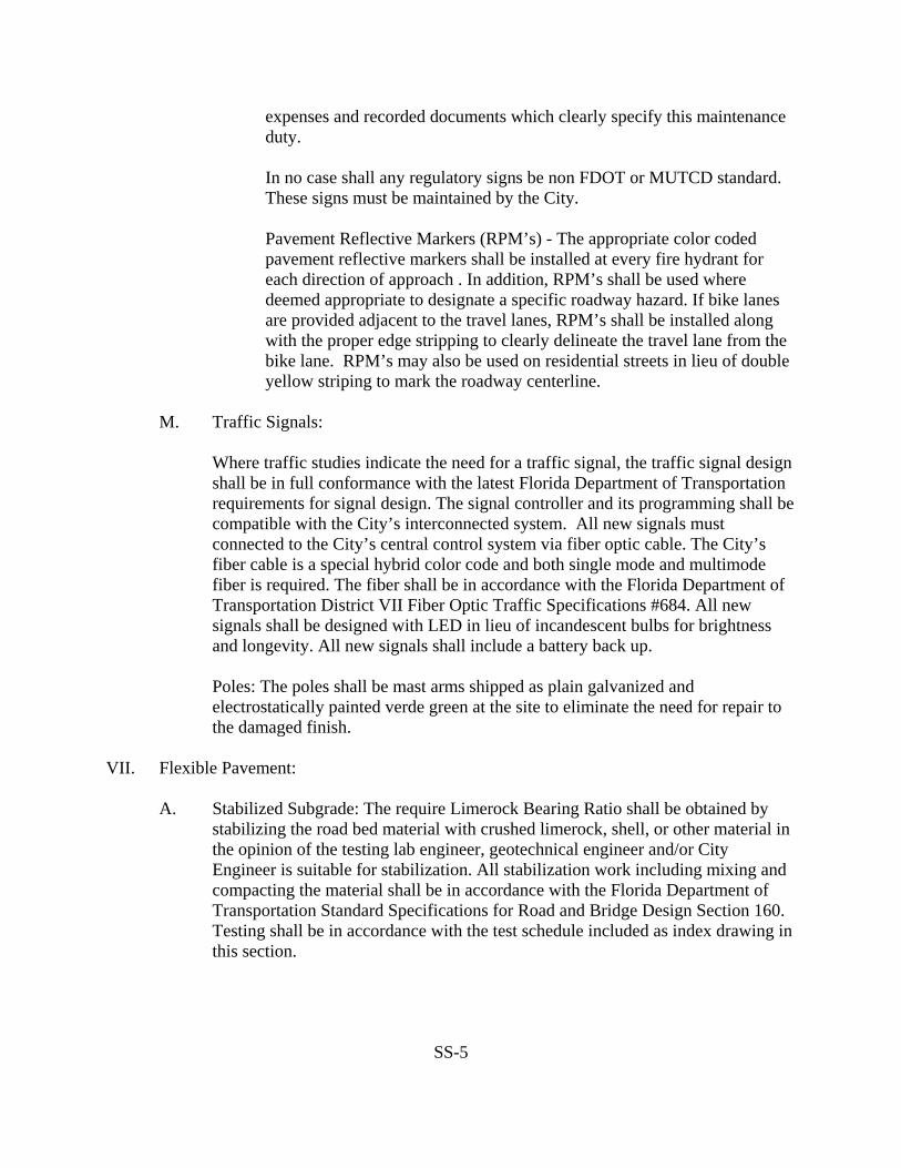
expenses and recorded documents which clearly specify this maintenance duty.
In no case shall any regulatory signs be non FDOT or MUTCD standard. These signs must be maintained by the City.
Pavement Reflective Markers (RPM’s) - The appropriate color coded pavement reflective markers shall be installed at every fire hydrant for each direction of approach . In addition, RPM’s shall be used where deemed appropriate to designate a specific roadway hazard. If bike lanes are provided adjacent to the travel lanes, RPM’s shall be installed along with the proper edge stripping to clearly delineate the travel lane from the bike lane. RPM’s may also be used on residential streets in lieu of double yellow striping to mark the roadway centerline.
M. Traffic Signals:
Where traffic studies indicate the need for a traffic signal, the traffic signal design shall be in full conformance with the latest Florida Department of Transportation requirements for signal design. The signal controller and its programming shall be compatible with the City’s interconnected system. All new signals must connected to the City’s central control system via fiber optic cable. The City’s fiber cable is a special hybrid color code and both single mode and multimode fiber is required. The fiber shall be in accordance with the Florida Department of Transportation District VII Fiber Optic Traffic Specifications #684. All new signals shall be designed with LED in lieu of incandescent bulbs for brightness and longevity. All new signals shall include a battery back up.
Poles: The poles shall be mast arms shipped as plain galvanized and electrostatically painted verde green at the site to eliminate the need for repair to the damaged finish.
VII. Flexible Pavement: A. Stabilized Subgrade: The require Limerock Bearing Ratio shall be obtained by
stabilizing the road bed material with crushed limerock, shell, or other material in the opinion of the testing lab engineer, geotechnical engineer and/or City Engineer is suitable for stabilization. All stabilization work including mixing and compacting the material shall be in accordance with the Florida Department of Transportation Standard Specifications for Road and Bridge Design Section 160. Testing shall be in accordance with the test schedule included as index drawing in this section.

SS-6
B. Base Course: The City preferred base course material is crushed concrete
regardless of water table elevation. Limerock and other base materials may be permitted to be used if the soil and water table elevations permit. A low strength Soil cement of 300 psi is permitted if a geo-textile fabric is used to try and limit the surface cracking typically associated with this type of base. All material, methods, compacting ,finishing etc shall be in accordance with the Florida Department of Transportation of Roadway and Bridge Design Sections 200, 210,250,270,280 and 285.
Minimum depth below the bottom of the base to the seasonal high water for limerock is two feet and one foot for a water resistant base such as crushed concrete. If the seasonal high water table exceeds these depth requirements underdrain must be used.
Testing shall be in accordance with the test schedule included as index drawing in this section.
C. Prime and Tack Coat: The materials, equipment, cleaning the base, weather
limitations, application of the prime or tack coat shall be in accordance with the Florida Department of Transportation Standard Specifications for Road and Bridges Section 300.
D. Surface Coarse - A wearing surface shall be constructed conforming to Section
331, Type S-1 or S-3 Asphaltic Concrete, and Sections 320 Hot Bituminous Plant Methods and Equipment and 330 Hot Bituminous Mixtures General Requirements.
No recycled asphalt is permitted. Maximum under tolerance in asphalt thickness
is 1/4 inch. Testing shall be in accordance with the testing schedule included as an index drawing in this section.
VIII Testing:
All testing of materials or field tests specified by the Florida Department of Transportation and the City shall be performed by an independent testing laboratory employed by the developer. A testing schedule is included as an index drawing in this specification.
IX. Record Drawings:
The developer shall submit to the City Engineer two sets of signed and sealed record drawings, one set of reproducible drawings and one set of electronic files produced or compatible with the latest version of AutoCAD. The record drawings shall accurately depict the constructed improvements with actual roadway profile

SS-7
grades along the centerline, edge of pavement, curb lines etc. Sufficient topographic elevations must be provided to clearly delineate grading and drainage patterns. At least three points scattered throughout the subdivision shall be tied to state plain coordinates. At least one permanent bench mark with elevation and coordinates must be placed in the subdivision. The location in plan and profile of all above and below ground improvements is required. Distances shall be measured from edge of pavement or road centerline for ease of future location. The location and depth of all service laterals must be shown on the drawings referenced to a permanent or fixed reference for ease of future location.
For infrastructure management and inventory, the as-builts shall list the total linear feet of roadway constructed, linear feet of curbing, sidewalks, and shall provide the costs of each item.

SS-8
TESTING SCHEDULEITEM TEST TEST IDENTIFICATION TEST REQUIREMENTS TEST FREQUENCY
Maximum Density Optimum Moisture
AASHTO T99 N/A Per soil type
Embankment Field Density AASHTO T191, T205, T238
ASTM, D2167, D29221 100% of Maximum Density One per 500' horizontally, each
lift (1 ft.) Maximum Density Optimum Moisture
AASHTO T180 N/A Per soil type
Utility Trench Backfill Field Density AASHTO T191, T205, T238
ASTM D1556, D2937, D29221 98 % of Maximum Density *, **
Maximum Density Optimum Moisture
AASHTO T180 N/A Per soil type Backfill of Structures Field Density AASHTO T191, T205, T238, ASTM
2957, ASTM D1556, D2167, D2922198% of Maximum Density **
Bearing Value FDOT LBR, LBR 40 **
Maximum Density Optimum Moisture
AASHTO T180 N/A One per Material Type, **
Field Density AASHTO T191, T238 98% OF Maximum Density ** Stabilized Subgrade
Thickness Field Measure Per Plans **
Bearings Values FDOT LBR LBR 100 One per Source
Maximum Density Optimum Moisture
AASHTO T180 N/A One per Source
Field Density ASHTO T1191, T238 98% OF Maximum Density **
Thickness Filed Measure Per Plans **
Limerock Base
Material FDOT Special Section 911 Per Specifications One per Source
Figure 1 Standards for Streets and Other Related Facilities ** Test shall be located no more than 300' - 500' apart. Tests shall be performed on each lift, except that test shall not be further apart than one foot vertically. Field
densities shall be taken over all road crossings. Field densities for sanitary lines shall be staggered to include results over service laterals. There shall be a minimum of one test series for each one foot of lift over pipeline between manholes. Tests around structures shall be spiraled in one foot lifts.
** Test shall be located no more than 200' apart. There shall be no less than one test per location. Note: Inspector reserves the right out call out extra test beyond what is shown above

TESTING SCHEDULE CONTINUED
ITEM TEST TEST IDENTIFICATION TEST REQUIREMENTS TEST FREQUENCY Mix Design, % Cement Strength Design
Florida Test Method FM 5-520 FDOT Spec Section 270
Per FDOT Specifications One per Material Type
Maximum Density Optimum Moisture
AASHTO T134 N/A One per Material Type
Compressive Strength Specifications
Florida Test Method FM 5-520 Per FDOT Specifications 300 PSI
One set of three per Material Type daily
Test Core Thickness Field Measure Per FDOT Specifications *
Soil Cement Base
Field Density AASHTO T238 ASTM D2922
97% of Maximum Density *
Slump Test AASHTO T23, T22 ASTM C31, C39
Per FDOT Specifications for type of concrete
One per set of cylinders
Compressive Strength Cylinders
AASHTO T23, T22 ASTM C31, C39
N/A One set of three cylinders for 100 CY or fraction thereof
Concrete
Air Content AASHTO T152, T196, T199 Per FDOT Specification 1 test per 100 CY
Aggregate Analysis Per FDOT Specifications Per FDOT Specifications One per Design
Design Mix One per Type Mix
Bitumen Content One per Day
Gradetion Stability/Flow One per Day
Field Density 1 per 1,000 LF of paving width
Properties of In-Place Material One per Day
Asphaltic Concreete Type “S” ***
Thickness *
Figure 2 Standards for Streets and Other Related Facilities ** Test shall be located no more than 200' apart. There shall be no less than one test per street. *** FDOT specifications to be supplemented with jurisdictional agency specifications where applicable.
SS-9

SS-10

SS-11

SS-12

SS-13

SS-14

SS-15

SS-16

SS-17

SS-18
SS-19
SS-20

SS-21

SS-22

SS-23