designations of overhead wiring conductor systems · overhead wiring conductor system selection....
TRANSCRIPT

Designations of Overhead Wiring Conductor Systems
T HR EL 08009 ST
Standard
Version 1.0
Issued Date: 08 July 2015
Important Warning This document is one of a set of standards developed solely and specifically for use on public transport assets which are vested in or owned, managed, controlled, commissioned or funded by the NSW Government, a NSW Government agency or a Transport Agency (as defined in the Asset Standards Authority Charter). It is not suitable for any other purpose. You must not use or adapt it or rely upon it in any way unless you are authorised in writing to do so by a relevant NSW Government agency. If this document forms part of a contract with, or is a condition of approval by, a NSW Government agency, use of the document is subject to the terms of the contract or approval. This document may not be current. Current standards are available for download from the Asset Standards Authority website at www.asa.transport.nsw.gov.au. © State of NSW through Transport for NSW
T HR EL 08009 ST Designations of Overhead Wiring Conductor Systems
Version 1.0 Issued Date: 08 July 2015
Standard governance
Owner: Lead Electrical Engineer, Asset Standards Authority
Authoriser: Chief Engineer Rail, Asset Standards Authority
Approver: Director, Asset Standards Authority on behalf of ASA Configuration Control Board
Document history
Version Summary of change
1.0 First issue
For queries regarding this document, please email the ASA at [email protected] or visit www.asa.transport.nsw.gov.au
© State of NSW through Transport for NSW

T HR EL 08009 ST Designations of Overhead Wiring Conductor Systems
Version 1.0 Issued Date: 08 July 2015
Preface The Asset Standards Authority (ASA) is an independent unit within Transport for NSW (TfNSW)
and is the network design and standards authority for defined NSW transport assets.
The ASA is responsible for developing engineering governance frameworks to support industry
delivery in the assurance of design, safety, integrity, construction, and commissioning of
transport assets for the whole asset life cycle. In order to achieve this, the ASA effectively
discharges obligations as the authority for various technical, process, and planning matters
across the asset life cycle.
The ASA collaborates with industry using stakeholder engagement activities to assist in
achieving its mission. These activities help align the ASA to broader government expectations of
making it clearer, simpler, and more attractive to do business within the NSW transport industry,
allowing the supply chain to deliver safe, efficient, and competent transport services.
The ASA develops, maintains, controls, and publishes a suite of standards and other
documentation for transport assets of TfNSW. Further, the ASA ensures that these standards
are performance based to create opportunities for innovation and improve access to a broader
competitive supply chain.
This standard supersedes RailCorp standard EP 08 00 00 16 SP Designations of Overhead
Wiring Conductor Systems, version 2.1.
The changes to previous content include the following:
• updates to reflect organisational changes and resulting changes in responsibilities
• minor amendments and clarification to content
• conversion of the standard to ASA numbering, format, and style
© State of NSW through Transport for NSW Page 3 of 19
T HR EL 08009 ST Designations of Overhead Wiring Conductor Systems
Version 1.0 Issued Date: 08 July 2015
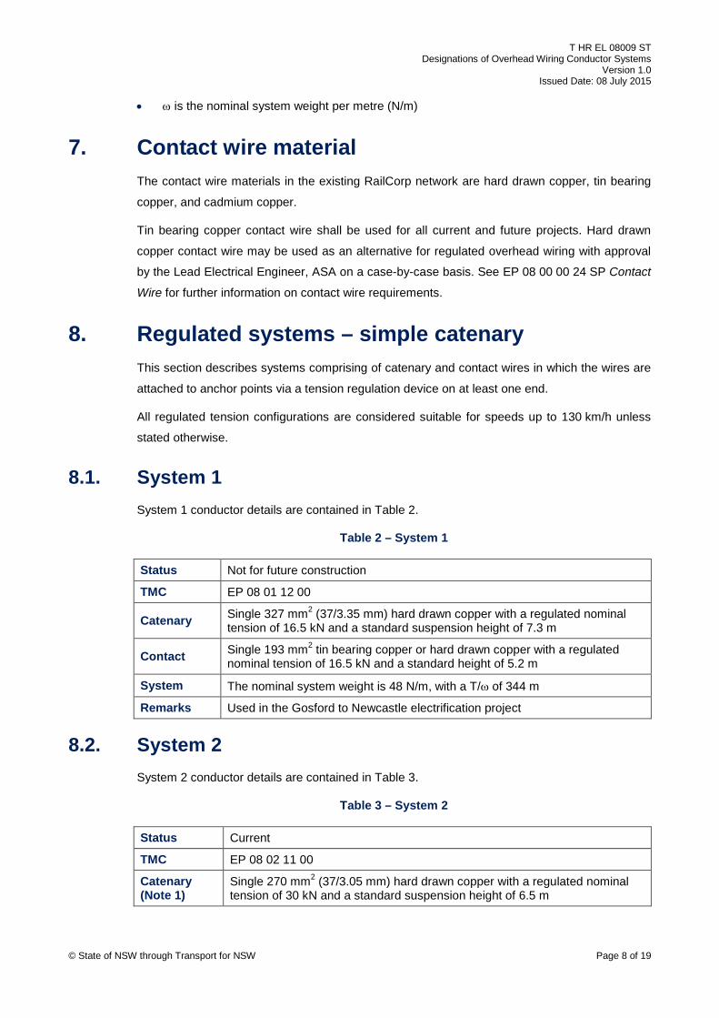
Table of contents 1. Introduction ............................................................................................................................................ 5
2. Purpose ................................................................................................................................................... 5 2.1. Scope ..................................................................................................................................................................... 5 2.2. Application ............................................................................................................................................................. 5 3. Reference documents ........................................................................................................................... 5
4. Terms and definitions ........................................................................................................................... 6
5. Status of overhead wiring conductor systems ................................................................................... 6 6. Summary of overhead wiring conductor systems ............................................................................. 6
7. Contact wire material ............................................................................................................................ 8
8. Regulated systems – simple catenary ................................................................................................. 8 8.1. System 1 ................................................................................................................................................................ 8 8.2. System 2 ................................................................................................................................................................ 8 8.3. System 3 ................................................................................................................................................................ 9 8.4. System 4 ................................................................................................................................................................ 9 8.5. System 5 .............................................................................................................................................................. 10 8.6. System 6 .............................................................................................................................................................. 10 8.7. System 7 .............................................................................................................................................................. 11 8.8. System 8 .............................................................................................................................................................. 11 8.9. System 9 .............................................................................................................................................................. 11 8.10. System 10 ............................................................................................................................................................ 12 8.11. System 12 ............................................................................................................................................................ 12 8.12. System 13 ............................................................................................................................................................ 13 8.13. System 15 ............................................................................................................................................................ 13 9. Regulated systems – contact only ..................................................................................................... 14 9.1. System 14 ............................................................................................................................................................ 14 10. Fixed anchored systems – simple catenary ..................................................................................... 14 10.1. System 21 ............................................................................................................................................................ 14 10.2. System 22 ............................................................................................................................................................ 15 10.3. System 23 ............................................................................................................................................................ 15 10.4. System 24 ............................................................................................................................................................ 16 10.5. System 25 ............................................................................................................................................................ 16 10.6. System 26 ............................................................................................................................................................ 16 10.7. System 28 ............................................................................................................................................................ 17 10.8. System 33 ............................................................................................................................................................ 17 10.9. System 34 ............................................................................................................................................................ 17 10.10. System 35 ............................................................................................................................................................ 18 11. Fixed anchored systems – contact only ........................................................................................... 18 11.1. System 36 ............................................................................................................................................................ 18 12. Fixed anchored systems – compound catenary .............................................................................. 19 12.1. System 27 ............................................................................................................................................................ 19
© State of NSW through Transport for NSW Page 4 of 19

T HR EL 08009 ST Designations of Overhead Wiring Conductor Systems
Version 1.0 Issued Date: 08 July 2015
1. Introduction Overhead wiring (OHW) is used to transmit power from traction substations to electric trains.
OHW generally consists of catenary and contact wires. The contact wire provides a
mechanically continuous path for train pantographs, and the catenary wire is used to support
the contact wire. The traction current to the trains is carried by both the catenary and contact
wires.
2. Purpose The purpose of this document is to list all overhead wiring conductor systems that have been
used in the RailCorp network and to provide a consistent shorthand designation for each
conductor configuration.
2.1. Scope The scope of this document is for 1500 V dc overhead wiring conductor systems as used in the
RailCorp network.
For new installations, all conductors shall be in accordance with T HR EL 08004 ST Overhead
Wiring Fittings and Materials. Contact wires shall also comply with EP 08 00 00 24 SP Contact
Wire.
For information on the process of selecting a suitable OHW system, refer to EP 08 00 00 17 SP
Overhead Wiring Conductor System Selection.
2.2. Application This document provides a detailed description of each overhead wiring conductor system that
has been assigned a Technical Maintenance Code (TMC).
This document is not to be used as a reference for the actual overhead wiring conductor system
installed at a particular location.
3. Reference documents Transport for NSW standards
EP 08 00 00 01 SP Overhead Wiring Standards for the Electrification of New Routes
EP 08 00 00 10 SP Overhead Wiring Layouts – Requirements and Symbology
EP 08 00 00 17 SP Overhead Wiring Conductor System Selection
EP 08 00 00 24 SP Contact Wire
T HR EL 08004 ST Overhead Wiring Fittings and Materials
© State of NSW through Transport for NSW Page 5 of 19

T HR EL 08009 ST Designations of Overhead Wiring Conductor Systems
Version 1.0 Issued Date: 08 July 2015
T MU AM 01008 ST Technical Maintenance Plans and Coding System
4. Terms and definitions The following terms and definitions apply in this document:
ASA Asset Standards Authority
NFC Not for Future Construction
OHW Overhead Wiring
Presag the process of deliberately lowering the contact wire (below the straight line between
the contact wire registration points at consecutive support locations) towards mid-bay in a
regulated overhead wiring system
TfNSW Transport for New South Wales
TMC Technical Maintenance Code
5. Status of overhead wiring conductor systems Each overhead wiring conductor system listed in this document is assigned one of the following
status categories:
• current - an OHW conductor system approved for use for the electrification of new routes,
and for the major rehabilitation of existing infrastructure. See EP 08 00 00 01 SP.
• Not for Future Construction (NFC) – the OHW conductor system may remain in service
where already installed. This configuration shall not be used for future construction. When
approved via a concession, the configuration may be used for extensions and alterations to
equipment of the same configuration.
• obsolete – OHW of this configuration shall not to be used for future construction. Any
existing OHW should be programmed for renewal.
6. Summary of overhead wiring conductor systems The overhead wiring conductor systems used in the RailCorp network, the associated system
designation and status category are summarised in Table 1 below.
Table 1 – OHW conductor systems summary
System Type Catenary size (mm²)
Catenary nominal
tension (kN) Contact
size (mm²) Contact nominal
tension (kN) Status
1 Regulated 327 16.5 193 16.5 NFC
2 Regulated 270 30.0 2 x 137 12.5 each Current
3 Regulated 270 17.8 2 x 137 11.12 each NFC © State of NSW through Transport for NSW Page 6 of 19

T HR EL 08009 ST Designations of Overhead Wiring Conductor Systems
Version 1.0 Issued Date: 08 July 2015
System Type Catenary size (mm²)
Catenary nominal
tension (kN) Contact
size (mm²) Contact nominal
tension (kN) Status
4 Regulated 270 15.6 193 15.6 NFC
5 Regulated 270 19.43 2 x 137 9.72 each NFC
6 Regulated 270 19.0 193 16.0 NFC
7 Regulated 510 34.6 193 18.0 NFC
8 Regulated 327 26.4 193 18.0 NFC
9 Regulated 270 23.1 193 18.0 Current
10 Regulated 165 18.15 193 18.0 Current
12 Regulated 2 x 270 20.35 each 2 x 137 12.5 each Current
13 Regulated 2 x 270 19.0 each 2 x 193 16.0 each NFC
14 Regulated N/A N/A 193 11.8 NFC
15 Regulated 2 x 165 15.4 each 2 x 137 12.5 each Current
21 Fixed anchored 270 15.9 193 13.35 NFC
22 Fixed anchored 270 14.15 137 9.34 NFC
23 Fixed anchored 327 17.92 193 13.35 NFC
24 Fixed anchored 510 24.11 193 13.35 Obsolete
25 Fixed anchored 165 12.37 193 13.35 NFC
26 Fixed anchored 165 10.99 137 12.46 Obsolete
27 Fixed anchored (Compound)
327 / 179 19.94 / 6.61 193 13.35 NFC
28 Fixed anchored 270 19.43 2 x 137 9.35 each Current
33 Fixed anchored 91 steel 9.52 193 13.35 Obsolete
34 Fixed anchored 91 steel 7.92 137 9.3 Obsolete
35 Fixed anchored 270 18.6 2 x 137 12.46 each NFC
36 Fixed anchored N/A N/A 193 13.35 NFC
Nominal tensions for fixed systems are at 21 °C, except for the following systems:
• system 27, the nominal tension is at 18 °C
• system 28, the nominal tension is at 25 °C for the tunnels of New Southern Railway (Airport
line) and the Epping to Chatswood line
OHW system details are shown on OHW layouts in accordance with EP 08 00 00 10 SP
Overhead Wiring Layouts – Requirements and Symbology.
Details of each conductor system are given in Sections 8, 9, 10, 11 and 12. Each conductor
system has a unique technical maintenance code (TMC) allocated to it in accordance with
T MU AM 01008 ST Technical Maintenance Plans and Coding System. The nominal system
weight and, where applicable, the quotient T/ω are given for each conductor system, where:
• T is the nominal catenary tension in newtons (N) © State of NSW through Transport for NSW Page 7 of 19
T HR EL 08009 ST Designations of Overhead Wiring Conductor Systems
Version 1.0 Issued Date: 08 July 2015
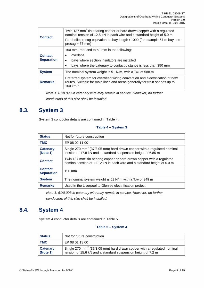
• ω is the nominal system weight per metre (N/m)
7. Contact wire material The contact wire materials in the existing RailCorp network are hard drawn copper, tin bearing
copper, and cadmium copper.
Tin bearing copper contact wire shall be used for all current and future projects. Hard drawn
copper contact wire may be used as an alternative for regulated overhead wiring with approval
by the Lead Electrical Engineer, ASA on a case-by-case basis. See EP 08 00 00 24 SP Contact
Wire for further information on contact wire requirements.
8. Regulated systems – simple catenary This section describes systems comprising of catenary and contact wires in which the wires are
attached to anchor points via a tension regulation device on at least one end.
All regulated tension configurations are considered suitable for speeds up to 130 km/h unless
stated otherwise.
8.1. System 1 System 1 conductor details are contained in Table 2.
Table 2 – System 1
Status Not for future construction
TMC EP 08 01 12 00
Catenary Single 327 mm2 (37/3.35 mm) hard drawn copper with a regulated nominal tension of 16.5 kN and a standard suspension height of 7.3 m
Contact Single 193 mm2 tin bearing copper or hard drawn copper with a regulated nominal tension of 16.5 kN and a standard height of 5.2 m
System The nominal system weight is 48 N/m, with a T/ω of 344 m
Remarks Used in the Gosford to Newcastle electrification project
8.2. System 2 System 2 conductor details are contained in Table 3.
Table 3 – System 2
Status Current
TMC EP 08 02 11 00
Catenary (Note 1)
Single 270 mm2 (37/3.05 mm) hard drawn copper with a regulated nominal tension of 30 kN and a standard suspension height of 6.5 m
© State of NSW through Transport for NSW Page 8 of 19
T HR EL 08009 ST Designations of Overhead Wiring Conductor Systems
Version 1.0 Issued Date: 08 July 2015
Contact
Twin 137 mm2 tin bearing copper or hard drawn copper with a regulated nominal tension of 12.5 kN in each wire and a standard height of 5.0 m Parabolic presag equivalent to bay length / 1000 (for example 67 m bay has presag = 67 mm)
Contact Separation
150 mm, reduced to 50 mm in the following: • overlaps • bays where section insulators are installed • bays where the catenary to contact distance is less than 350 mm
System The nominal system weight is 51 N/m, with a T/ω of 588 m
Remarks Preferred system for overhead wiring conversion and electrification of new routes. Suitable for main lines and areas generally for train speeds up to 160 km/h
Note 1: 61/0.093 in catenary wire may remain in service. However, no further
conductors of this size shall be installed.
8.3. System 3 System 3 conductor details are contained in Table 4.
Table 4 – System 3
Status Not for future construction
TMC EP 08 02 11 00
Catenary (Note 1)
Single 270 mm2 (37/3.05 mm) hard drawn copper with a regulated nominal tension of 17.8 kN and a standard suspension height of 6.85 m
Contact Twin 137 mm2 tin bearing copper or hard drawn copper with a regulated nominal tension of 11.12 kN in each wire and a standard height of 5.0 m
Contact Separation 150 mm
System The nominal system weight is 51 N/m, with a T/ω of 349 m
Remarks Used in the Liverpool to Glenlee electrification project
Note 1: 61/0.093 in catenary wire may remain in service. However, no further
conductors of this size shall be installed.
8.4. System 4 System 4 conductor details are contained in Table 5.
Table 5 – System 4
Status Not for future construction
TMC EP 08 01 13 00
Catenary (Note 1)
Single 270 mm2 (37/3.05 mm) hard drawn copper with a regulated nominal tension of 15.6 kN and a standard suspension height of 7.2 m
© State of NSW through Transport for NSW Page 9 of 19

T HR EL 08009 ST Designations of Overhead Wiring Conductor Systems
Version 1.0 Issued Date: 08 July 2015
Contact Single 193 mm2 tin bearing copper or hard drawn copper with a regulated nominal tension of 15.6 kN and a standard height of 5.2 m
System The nominal system weight is 42 N/m, with a T/ω of 371 m
Remarks Used in overhead wiring conversion projects in the early 1980’s including Wolli Creek to Kingsgrove and Lidcombe to Liverpool
Note 1: 61/0.093 in catenary wire may remain in service. However, no further
conductors of this size shall be installed.
8.5. System 5 System 5 conductor details are contained in Table 6.
Table 6 – System 5
Status Not for future construction
TMC EP 08 02 11 00
Catenary (Note 1)
Single 270 mm2 (37/3.05 mm) hard drawn copper with a regulated nominal tension of 19.43 kN
Contact Twin 137 mm2 tin bearing copper or hard drawn copper with a regulated nominal tension of 9.72 kN in each wire and a standard height of 4.8 m
Contact Separation 50 mm
System The nominal system weight is 51 N/m, with a T/ω of 381 m
Remarks Used on the Eastern Suburbs Railway (ESR) line viaducts
Note 1: 61/0.093 in catenary wire may remain in service. However, no further
conductors of this size shall be installed.
8.6. System 6 System 6 conductor details are contained in Table 7.
Table 7 – System 6
Status Not for future construction
TMC EP 08 01 13 00
Catenary (Note 1)
Single 270 mm2 (37/3.05 mm) hard drawn copper with a regulated nominal tension of 19.0 kN and a standard suspension height of 6.8 m
Contact Single 193 mm2 tin bearing copper or hard drawn copper with a regulated nominal tension of 16.0 kN and a standard height of 5.2 m
System The nominal system weight is 42 N/m, with a T/ω of 452 m
Remarks Used for Illawarra crossovers in the Waterfall to Port Kembla electrification project
Note 1: 61/0.093 in catenary wire may remain in service. However, no further
conductors of this size shall be installed.
© State of NSW through Transport for NSW Page 10 of 19

T HR EL 08009 ST Designations of Overhead Wiring Conductor Systems
Version 1.0 Issued Date: 08 July 2015
8.7. System 7 System 7 conductor details are contained in Table 8.
Table 8 – System 7
Status Not for future construction
TMC EP 08 01 11 00
Catenary Single 510 mm2 (37/4.19 mm) hard drawn copper with a regulated nominal tension of 34.6 kN and a standard suspension height of 6.5 m
Contact
Single 193 mm2 tin bearing copper or hard drawn copper with a regulated nominal tension of 18.0 kN and a standard height of 5.0 m Parabolic presag equivalent to bay length / 1000 (for example 67 m bay has presag = 67 mm)
System The nominal system weight is 63 N/m, with a T/ω of 550 m
Remarks Used for overhead wiring conversion projects between Hornsby and Woy Woy
8.8. System 8 System 8 conductor details are contained in Table 9.
Table 9 – System 8
Status Not for future construction
TMC EP 08 01 12 00
Catenary Single 327 mm2 (37/3.35 mm) hard drawn copper with a regulated nominal tension of 26.4 kN and a standard suspension height of 6.5 m
Contact
Single 193 mm2 tin bearing copper or hard drawn copper with a regulated nominal tension of 18.0 kN and a standard height of 5.0 m Parabolic presag equivalent to bay length / 1000 (for example 67 m bay has presag = 67 mm)
System The nominal system weight is 48 N/m, with a T/ω of 550 m
Remarks Used in the Riverstone to Richmond electrification project and the overhead wiring conversion project between Woy Woy and Gosford
8.9. System 9 System 9 conductor details are contained in Table 10.
Table 10 – System 9
Status Current
TMC EP 08 01 13 00
Catenary (Note 1)
Single 270 mm2 (37/3.05 mm) hard drawn copper with a regulated nominal tension of 23.1 kN and a standard suspension height of 6.5 m
© State of NSW through Transport for NSW Page 11 of 19

T HR EL 08009 ST Designations of Overhead Wiring Conductor Systems
Version 1.0 Issued Date: 08 July 2015
Contact
Single 193 mm2 tin bearing copper or hard drawn copper with a regulated nominal tension of 18.0 kN and a standard height of 5.0 m Parabolic presag equivalent to bay length / 1000 (for example 67 m bay has presag = 67 mm)
System The nominal system weight is 42 N/m, with a T/ω of 550 m
Remarks Suitable for main lines subject to medium traffic densities and is the preferred system for crossovers, sidings, and refuges
Note 1: 61/0.093 in catenary wire may remain in service. However, no further
conductors of this size shall be installed.
8.10. System 10 System 10 conductor details are contained in Table 11.
Table 11 – System 10
Status Current
TMC EP 08 01 14 00
Catenary Single 165 mm2 (19/3.35 mm) hard drawn copper with a regulated nominal tension of 18.15 kN and a standard suspension height of 6.5 m
Contact Single 193 mm2 tin bearing copper or hard drawn copper with a regulated nominal tension of 18.0 kN and a standard height of 5.0 m Parabolic presag equivalent to bay length / 1000 (for example 67 m bay has presag = 67 mm)
System The nominal system weight is 33 N/m, with a T/ω of 550 m
Remarks Used in crossovers, yards, and sidings within the electrified area where train speeds are less than 80 km/h and current carrying capacity is adequate
8.11. System 12 System 12 conductor details are contained in Table 12.
Table 12 – System 12
Status Current
TMC EP 08 04 01 00
Catenary Twin 270 mm2 (37/3.05 mm) hard drawn copper with a regulated nominal tension of 20.35 kN in each wire and a standard suspension height of 6.5 m
Catenary Separation 150 mm
Contact
Twin 137 mm2 tin bearing copper or hard drawn copper with a regulated nominal tension of 12.5 kN in each wire and a standard height of 5.0 m Parabolic presag equivalent to bay length / 1000 (for example 67 m bay has presag = 67 mm)
Contact Separation 150 mm, reduced to 50 mm in bays where section insulators are installed
System The nominal system weight is 74 N/m, with a T/ω of 550 m
© State of NSW through Transport for NSW Page 12 of 19
T HR EL 08009 ST Designations of Overhead Wiring Conductor Systems
Version 1.0 Issued Date: 08 July 2015
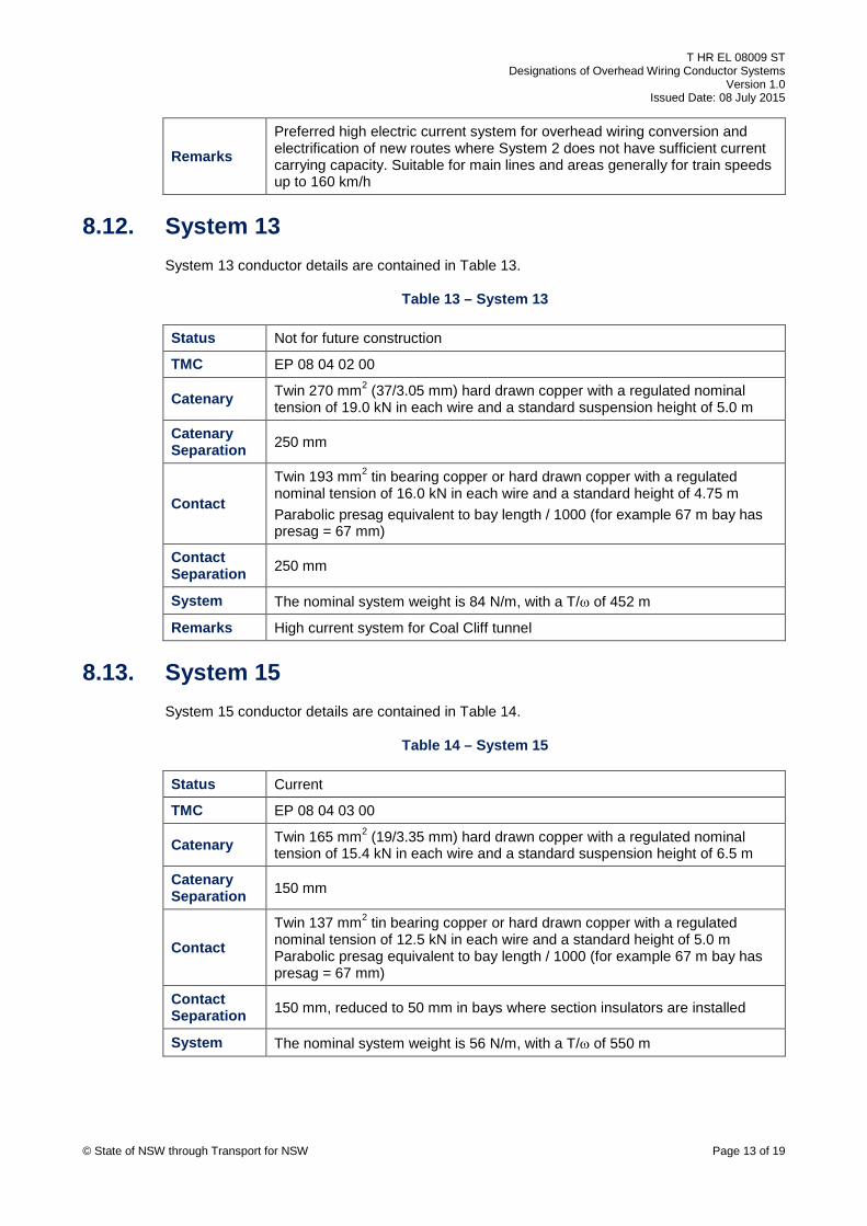
Remarks Preferred high electric current system for overhead wiring conversion and electrification of new routes where System 2 does not have sufficient current carrying capacity. Suitable for main lines and areas generally for train speeds up to 160 km/h
8.12. System 13 System 13 conductor details are contained in Table 13.
Table 13 – System 13
Status Not for future construction
TMC EP 08 04 02 00
Catenary Twin 270 mm2 (37/3.05 mm) hard drawn copper with a regulated nominal tension of 19.0 kN in each wire and a standard suspension height of 5.0 m
Catenary Separation 250 mm
Contact
Twin 193 mm2 tin bearing copper or hard drawn copper with a regulated nominal tension of 16.0 kN in each wire and a standard height of 4.75 m Parabolic presag equivalent to bay length / 1000 (for example 67 m bay has presag = 67 mm)
Contact Separation 250 mm
System The nominal system weight is 84 N/m, with a T/ω of 452 m
Remarks High current system for Coal Cliff tunnel
8.13. System 15 System 15 conductor details are contained in Table 14.
Table 14 – System 15
Status Current
TMC EP 08 04 03 00
Catenary Twin 165 mm2 (19/3.35 mm) hard drawn copper with a regulated nominal tension of 15.4 kN in each wire and a standard suspension height of 6.5 m
Catenary Separation 150 mm
Contact Twin 137 mm2 tin bearing copper or hard drawn copper with a regulated nominal tension of 12.5 kN in each wire and a standard height of 5.0 m Parabolic presag equivalent to bay length / 1000 (for example 67 m bay has presag = 67 mm)
Contact Separation 150 mm, reduced to 50 mm in bays where section insulators are installed
System The nominal system weight is 56 N/m, with a T/ω of 550 m
© State of NSW through Transport for NSW Page 13 of 19

T HR EL 08009 ST Designations of Overhead Wiring Conductor Systems
Version 1.0 Issued Date: 08 July 2015
Remarks
Alternate high electric current system for OHW conversion and electrification of new routes where System 2 does not have sufficient current carrying capacity, but where the high mechanical loads of the twin 270 mm² catenary OHW system (System 12) are to be avoided, for example on existing OHW structures. The mechanical loads of this system are only marginally greater than that of System 2. Suitable for main lines and areas generally for train speeds up to 160 km/h
9. Regulated systems – contact only This section describes systems comprising of one or more contact wires only (with no
supporting catenary) in which the contact wires are attached to anchor points via a tension
regulator device at least at one end. These systems are suitable for very low speed operation
only.
9.1. System 14 System 14 conductor details are contained in Table 15.
Table 15 – System 14
Status Not for future construction
TMC EP 08 03 11 00
Contact Single 193 mm2 tin bearing copper or hard drawn copper with a regulated nominal tension of 11.8 kN and a standard height of 5.3 m
System The contact wire weight is 16.9 N/m
Remarks Used at Newnes balloon loop for very low speed (25 km/h) operation
10. Fixed anchored systems – simple catenary This section describes systems comprising of catenary and contact wires in which the catenary
and contact wires are attached to anchor points at both ends without any tension regulation
device.
10.1. System 21 System 21 conductor details are contained in Table 16.
Table 16 – System 21
Status Not for future construction
TMC EP 08 06 13 00
Catenary (Note 1)
Single 270 mm2 (37/3.05 mm) hard drawn copper with a nominal tension of 15.9 kN at 21 °C
Contact Single 193 mm2 cadmium copper or tin bearing copper with a nominal tension of 13.35 kN at 21 °C and a standard height of 5.0 m
© State of NSW through Transport for NSW Page 14 of 19
T HR EL 08009 ST Designations of Overhead Wiring Conductor Systems
Version 1.0 Issued Date: 08 July 2015
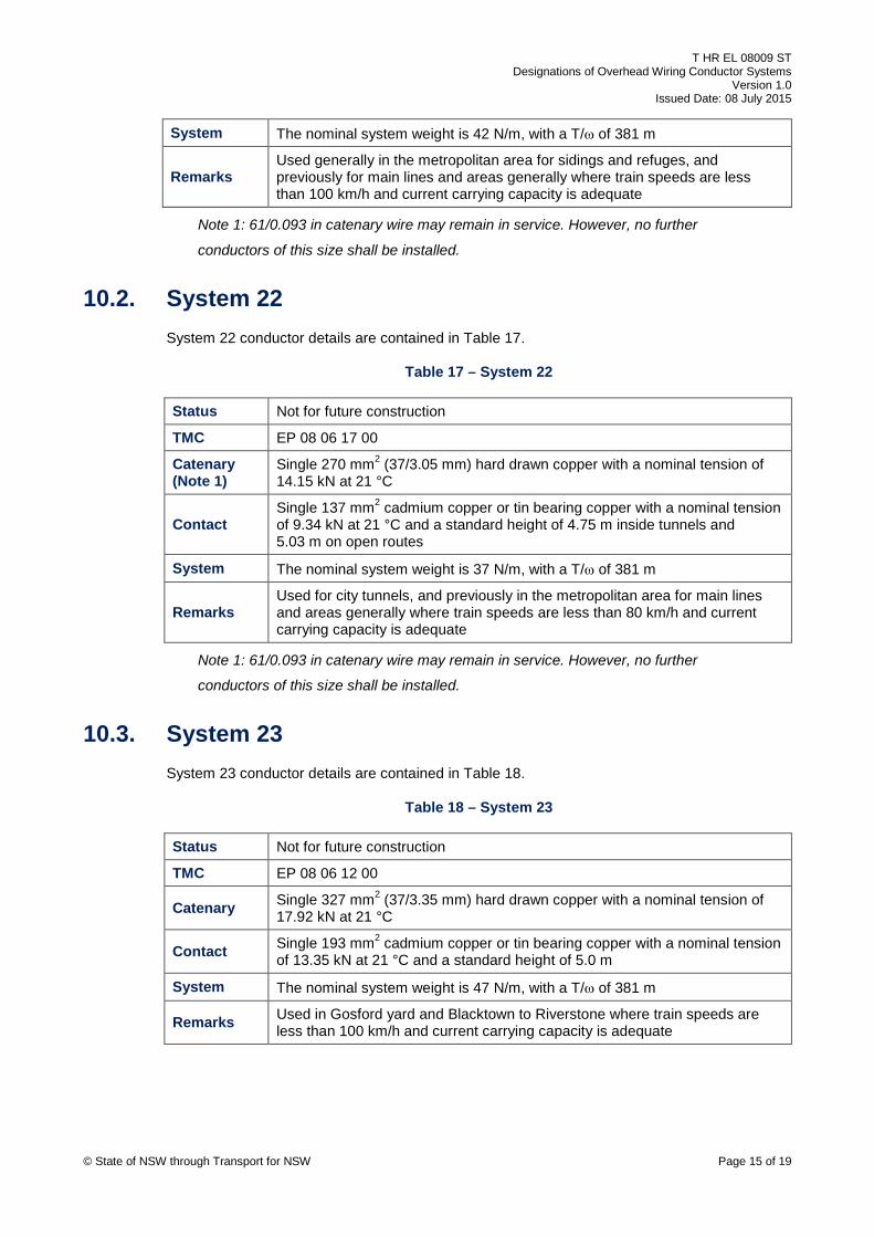
System The nominal system weight is 42 N/m, with a T/ω of 381 m
Remarks Used generally in the metropolitan area for sidings and refuges, and previously for main lines and areas generally where train speeds are less than 100 km/h and current carrying capacity is adequate
Note 1: 61/0.093 in catenary wire may remain in service. However, no further
conductors of this size shall be installed.
10.2. System 22 System 22 conductor details are contained in Table 17.
Table 17 – System 22
Status Not for future construction
TMC EP 08 06 17 00
Catenary (Note 1)
Single 270 mm2 (37/3.05 mm) hard drawn copper with a nominal tension of 14.15 kN at 21 °C
Contact Single 137 mm2 cadmium copper or tin bearing copper with a nominal tension of 9.34 kN at 21 °C and a standard height of 4.75 m inside tunnels and 5.03 m on open routes
System The nominal system weight is 37 N/m, with a T/ω of 381 m
Remarks Used for city tunnels, and previously in the metropolitan area for main lines and areas generally where train speeds are less than 80 km/h and current carrying capacity is adequate
Note 1: 61/0.093 in catenary wire may remain in service. However, no further
conductors of this size shall be installed.
10.3. System 23 System 23 conductor details are contained in Table 18.
Table 18 – System 23
Status Not for future construction
TMC EP 08 06 12 00
Catenary Single 327 mm2 (37/3.35 mm) hard drawn copper with a nominal tension of 17.92 kN at 21 °C
Contact Single 193 mm2 cadmium copper or tin bearing copper with a nominal tension of 13.35 kN at 21 °C and a standard height of 5.0 m
System The nominal system weight is 47 N/m, with a T/ω of 381 m
Remarks Used in Gosford yard and Blacktown to Riverstone where train speeds are less than 100 km/h and current carrying capacity is adequate
© State of NSW through Transport for NSW Page 15 of 19
T HR EL 08009 ST Designations of Overhead Wiring Conductor Systems
Version 1.0 Issued Date: 08 July 2015
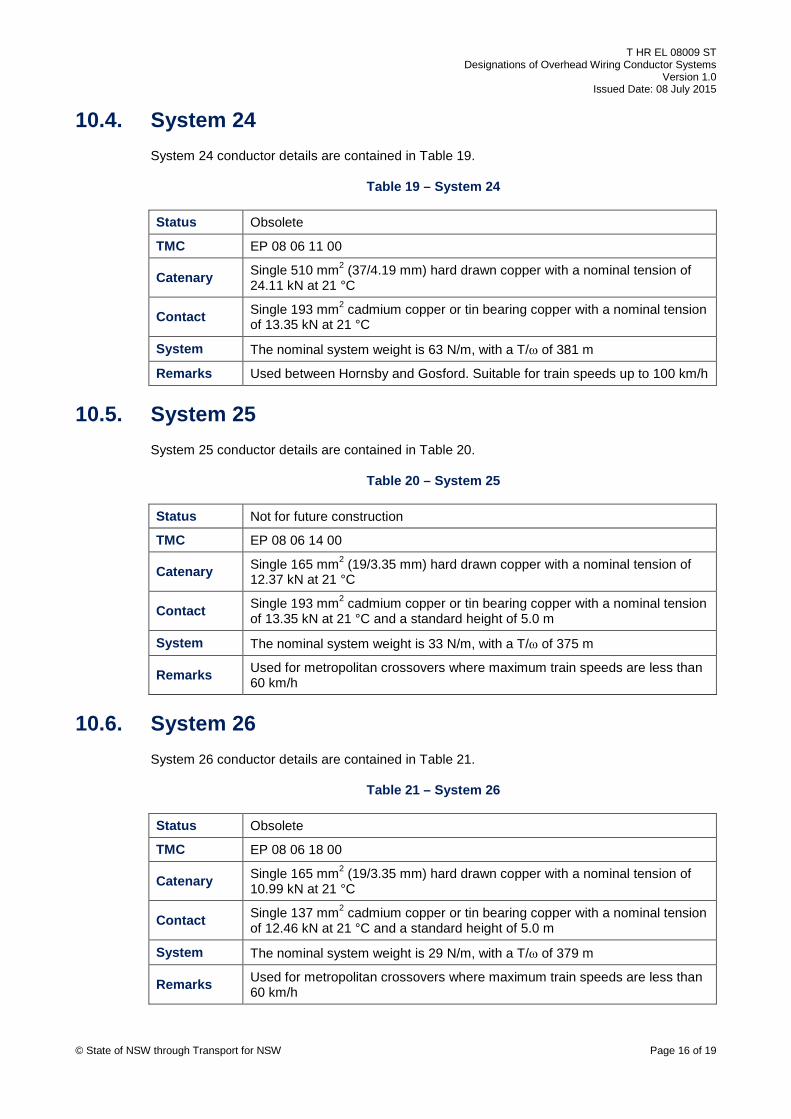
10.4. System 24 System 24 conductor details are contained in Table 19.
Table 19 – System 24
Status Obsolete
TMC EP 08 06 11 00
Catenary Single 510 mm2 (37/4.19 mm) hard drawn copper with a nominal tension of 24.11 kN at 21 °C
Contact Single 193 mm2 cadmium copper or tin bearing copper with a nominal tension of 13.35 kN at 21 °C
System The nominal system weight is 63 N/m, with a T/ω of 381 m
Remarks Used between Hornsby and Gosford. Suitable for train speeds up to 100 km/h
10.5. System 25 System 25 conductor details are contained in Table 20.
Table 20 – System 25
Status Not for future construction
TMC EP 08 06 14 00
Catenary Single 165 mm2 (19/3.35 mm) hard drawn copper with a nominal tension of 12.37 kN at 21 °C
Contact Single 193 mm2 cadmium copper or tin bearing copper with a nominal tension of 13.35 kN at 21 °C and a standard height of 5.0 m
System The nominal system weight is 33 N/m, with a T/ω of 375 m
Remarks Used for metropolitan crossovers where maximum train speeds are less than 60 km/h
10.6. System 26 System 26 conductor details are contained in Table 21.
Table 21 – System 26
Status Obsolete
TMC EP 08 06 18 00
Catenary Single 165 mm2 (19/3.35 mm) hard drawn copper with a nominal tension of 10.99 kN at 21 °C
Contact Single 137 mm2 cadmium copper or tin bearing copper with a nominal tension of 12.46 kN at 21 °C and a standard height of 5.0 m
System The nominal system weight is 29 N/m, with a T/ω of 379 m
Remarks Used for metropolitan crossovers where maximum train speeds are less than 60 km/h
© State of NSW through Transport for NSW Page 16 of 19

T HR EL 08009 ST Designations of Overhead Wiring Conductor Systems
Version 1.0 Issued Date: 08 July 2015
10.7. System 28 System 28 conductor details are contained in Table 22.
Table 22 – System 28
Status Current
TMC EP 08 07 11 00
Catenary (Note 1)
Single 270 mm2 (37/3.05 mm) hard drawn copper with a nominal tension of 19.43 kN at 21 °C
Contact Twin 137 mm2 cadmium copper or tin bearing copper with a nominal tension of 9.35 kN at 21 °C in each wire and a standard height of 4.75 m inside tunnels (5.03 m outside tunnels)
Contact Separation 50 mm
System The nominal system weight is 51 N/m, with a T/ω of 381 m
Remarks Used in the NSR and ESR tunnels. Preferred system for overhead wiring conversion and electrification of new routes in tunnels carrying non-freight traction currents if the current carrying capacity is adequate. Suitable for train speeds up to 115 km/h
Note 1: 61/0.093 in catenary wire may remain in service. However, no further
conductors of this size shall be installed.
10.8. System 33 System 33 conductor details are contained in Table 23.
Table 23 – System 33
Status Obsolete
TMC EP 08 06 41 00
Catenary Single 91 mm2 (7/4.06 mm) galvanized steel wire with a nominal tension of 9.52 kN at 21 °C
Contact Single 193 mm2 cadmium copper or tin bearing copper with a nominal tension of 13.35 kN at 21 °C and a standard height of 5.0 m
System The nominal system weight is 25 N/m, with a T/ω of 381 m
Remarks Used in some sidings and at crossovers. Suitable for train speeds up to 25 km/h
10.9. System 34 System 34 conductor details are contained in Table 24.
Table 24 – System 34
Status Obsolete
TMC EP 08 06 42 00
© State of NSW through Transport for NSW Page 17 of 19
T HR EL 08009 ST Designations of Overhead Wiring Conductor Systems
Version 1.0 Issued Date: 08 July 2015
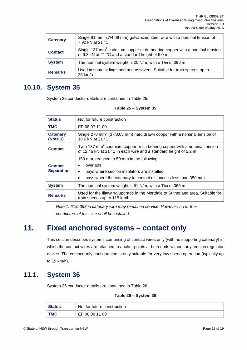
Catenary Single 91 mm2 (7/4.06 mm) galvanized steel wire with a nominal tension of 7.92 kN at 21 °C
Contact Single 137 mm2 cadmium copper or tin bearing copper with a nominal tension of 9.3 kN at 21 °C and a standard height of 5.0 m
System The nominal system weight is 20 N/m, with a T/ω of 396 m
Remarks Used in some sidings and at crossovers. Suitable for train speeds up to 25 km/h
10.10. System 35 System 35 conductor details are contained in Table 25.
Table 25 – System 35
Status Not for future construction
TMC EP 08 07 11 00
Catenary (Note 1)
Single 270 mm2 (37/3.05 mm) hard drawn copper with a nominal tension of 18.6 kN at 21 °C
Contact Twin 137 mm2 cadmium copper or tin bearing copper with a nominal tension of 12.46 kN at 21 °C in each wire and a standard height of 5.2 m
Contact Separation
150 mm, reduced to 50 mm in the following: • overlaps • bays where section insulators are installed • bays where the catenary to contact distance is less than 350 mm
System The nominal system weight is 51 N/m, with a T/ω of 365 m
Remarks Used for the Illawarra upgrade in the Mortdale to Sutherland area. Suitable for train speeds up to 115 km/h
Note 1: 61/0.093 in catenary wire may remain in service. However, no further
conductors of this size shall be installed.
11. Fixed anchored systems – contact only This section describes systems comprising of contact wires only (with no supporting catenary) in
which the contact wires are attached to anchor points at both ends without any tension regulator
device. The contact only configuration is only suitable for very low speed operation (typically up
to 15 km/h).
11.1. System 36 System 36 conductor details are contained in Table 26.
Table 26 – System 36
Status Not for future construction
TMC EP 08 08 11 00
© State of NSW through Transport for NSW Page 18 of 19

T HR EL 08009 ST Designations of Overhead Wiring Conductor Systems
Version 1.0 Issued Date: 08 July 2015
Contact Single 193 mm2 cadmium copper or tin bearing copper with a nominal tension of 13.35 kN at 21 °C and a standard height of 5.0 m (or 50 mm above when crossing mainline contact)
System The contact wire weight is 16.9 N/m
Remarks Used for areas with very low speed operation, for example, Sydney yard
12. Fixed anchored systems – compound catenary This section describes systems comprising of a main catenary, an auxiliary catenary, and a
contact wire in which the catenaries and contact wire are attached to anchor points at both ends
without any tension regulator device.
12.1. System 27 System 27 conductor details are contained in Table 27.
Table 27 – System 27
Status Not for future construction
TMC EP 08 09 11 00
Catenary Single 327 mm2 (37/3.35 mm) hard drawn copper with a nominal tension of 19.94 kN at 18 °C, and a standard suspension height of 7.53 m
Auxiliary Catenary
Single 179 mm2 (19/3.48 mm) hard drawn copper with a nominal tension of 6.61 kN at 18 °C
Contact Single 193 mm2 cadmium copper or tin bearing copper with a nominal tension of 13.35 kN at 18 °C and a standard height of 5.0 m
System The nominal system weight is 66 N/m, with a T/ω of 302 m
Remarks Used from Penrith to Lithgow over the main line, along with some crossovers and sidings. Suitable for train speeds up to 100 km/h
© State of NSW through Transport for NSW Page 19 of 19