designer’s guide - vandernet oy designer’s guide discusses in detail the factors that must ......
TRANSCRIPT

Issue No: 2 Issue Date: 01/10/2011
RoofSafe Rail Designer’s Guide
Always read and follow the warnings and instructions for use
© Copyright Capital Safety 2011
Designer’s Guide

2
1.0 Foreword 3
2.0 General 4
2.1 Authorised Installers
2.2 Conformity 4
2.3 Work Restraint, Fall Arrest & Suspended Access 4
2.4 Recommended Free Space & Free Fall Diagram2.5 Swing Fall
79
3.0 Site Assessment 10
3.1 Reviewing the Task 10
3.2 The Mounting Structure 11
3.3 Gaining Access to the System 11
3.4 Environmental Conditions 12
3.5 Environmental Impact 12
3.6 Rescue Planning 13
4.0 Designing Your System 16
4.1 Specifying the System 16
4.2 Forces on the System 19
4.3 Engineer’s Reference Table 22
5.0 Personal Protective Equipment 23
6.0 System Maintenance & Inspection 24
7.0 Reference Documents 28
7.1 Abbreviations and Definitions 28
7.2 Standards Table 29
7.3 Markings Explained 30
Contents
Issue No: 2Issue Date: 01/10/2011
RoofSafe Rail Designer’s Guide

It is important that this guide is read and fully understood before the RoofSafe Rail System is installed or serviced. This Designer’s Guide discusses in detail the factors that must be considered when designing, using and maintaining a RoofSafe Rail System. Incorrect installation or servicing through failure to adhere to these instructions could result in serious injury or death. It is the duty of the installer to ensure that the relevant standards and legislation are adhered to when installing, commissioning and handing over the system. In part these procedures fulfil the requirements in BS EN 795 and BS 7883 and is OSHA compliant, failure to comply with these procedures could result in non-compliance with these standards. These procedures comply with the requirements in Directive 89/686/EEC, failure to comply with these procedures could also result in non-compliance with legal requirements. It is important that supervisors and management ensure that personnel who they direct to install or service the RoofSafe Rail System are trained by Capital Safety and that the training complies with the relevant national standards, procedures and or guidelines.
This guide is an essential reference document for designing a RoofSafe Rail System.
Uniline® and RoofSafe® are registered trademarks of Capital Safety Group.
1. Foreword
3Issue No: 2Issue Date: 01/10/2011
RoofSafe Rail Designer’s Guide

2.1 Authorised InstallersOnly competent installers authorised by Capital Safety are allowed to install and service the RoofSafe Rail Safety System.
2.2 ConformityThe RoofSafe Rail System is a horizontal rail system which is tested and where appropriate certified in accordance with the requirements of European BS EN 795 (Class D) and the Australian Standard AS/NZS 1891.2 and is OSHA compliant. It meets the requirements of Council Directive 89/686/EEC by way of the UK transposition of 89/686/EEC: the Personal Protective Equipment (EC Directive) Regulations 1992.
Components or parts are not to be altered, modified, dismantled (beyond that allowed in this manual) or be replaced with items not supplied or manufactured by Capital Safety. This action will invalidate the above certification and could result in serious or fatal consequences. Parts or components not supplied by Capital Safety may be of inferior specification and may cause incorrect operation of the system.
2.3 Work Restraint, Fall Arrest & Suspended AccessThe RoofSafe Rail System is a complete fall protection system. It has been designed to solve problems relating to falls from a height. All RoofSafe Rail Systems for structures must be designed for fall arrest, although it is best to restrain the user to prevent an arrest occurring.
The RoofSafe Rail System can be used for both fall arrest and work restraint applications. For fall arrest, the system can accommodate up to two users (per 3 metre span) and for fall restraint the system can accommodate multiple users. In addition the rail can be used for rope access work.
WORK RESTRAINT
The advantages with work restraint are that:
• Workersdo not have tobe subjected to the abrupt impact of an arrest aswouldbethe case in a fall arrest system, or risk falling into a hazard e.g. water or a hazardous substance;
• Theusercannotbeinjuredfromfallincidents.
2. General
4Issue No: 2Issue Date: 01/10/2011
RoofSafe Rail Designer’s Guide
A
B
A
B
Fig. 1 Fig. 2
• Thereisnoneedforanyrescueprovision.
• Personnelrequirelesstraining.
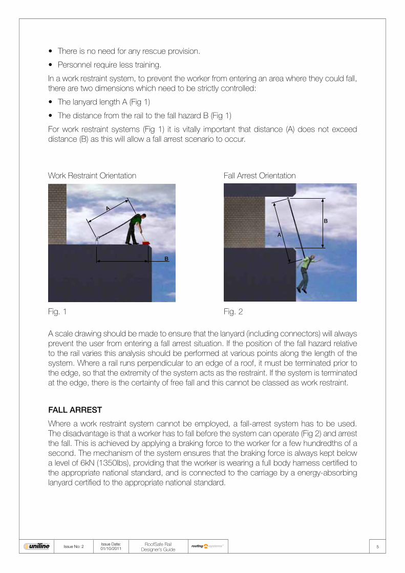
In a work restraint system, to prevent the worker from entering an area where they could fall, there are two dimensions which need to be strictly controlled:
•ThelanyardlengthA(Fig1)
• ThedistancefromtherailtothefallhazardB(Fig1)
For work restraint systems (Fig 1) it is vitally important that distance (A) does not exceed distance (B) as this will allow a fall arrest scenario to occur.
Fall Arrest OrientationWork Restraint Orientation
A scale drawing should be made to ensure that the lanyard (including connectors) will always prevent the user from entering a fall arrest situation. If the position of the fall hazard relative to the rail varies this analysis should be performed at various points along the length of the system. Where a rail runs perpendicular to an edge of a roof, it must be terminated prior to the edge, so that the extremity of the system acts as the restraint. If the system is terminated at the edge, there is the certainty of free fall and this cannot be classed as work restraint.
FALL ARREST
Where a work restraint system cannot be employed, a fall-arrest system has to be used. The disadvantage is that a worker has to fall before the system can operate (Fig 2) and arrest the fall. This is achieved by applying a braking force to the worker for a few hundredths of a second. The mechanism of the system ensures that the braking force is always kept below a level of 6kN (1350lbs), providing that the worker is wearing a full body harness certified to the appropriate national standard, and is connected to the carriage by a energy-absorbing lanyard certified to the appropriate national standard.
5Issue No: 2Issue Date: 01/10/2011
RoofSafe Rail Designer’s Guide

SUSPENDED ACCESS
For difficult to access areas a suspended access system may be used to allow a trained worker to abseil from the system (Fig 3). This type of system is best suited to short duration light to medium duties, such as inspections, window cleaning, and light maintenance tasks.
The continuous RoofSafe Rail System gives the user the ability to easily position themselves at any point along the system, via two carriages. The user can reposition themselves without ever having to detach from the system, meaning the user is always protected. The user should connect to the RoofSafe Rail via two carriages as prescribed in the rope access standard BS 7985, ATM E2505 and Australian Rope Access Association Industry Code 2005. One carriage is for the abseil/descent rope and the other for fall arrest/back up safety rope. The system must never be used without both carriages in place.
Suspended access systems should always be specified to be suitable for fall arrest, as there is always the possibility that the user may fall on the system. Fixing points for suspended access are positioned closer together in order to prevent deflection of the rail under load and to reduce any risk of fastener fatigue caused by repetitive loading.
Fig. 3
6Issue No: 2Issue Date: 01/10/2011
RoofSafe Rail Designer’s Guide
7Issue No: 2Issue Date: 01/10/2011
RoofSafe Rail Designer’s Guide
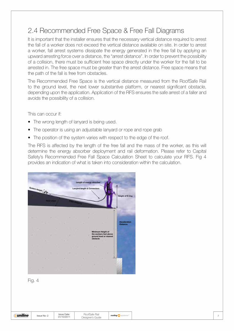
2.4 Recommended Free Space & Free Fall Diagrams It is important that the installer ensures that the necessary vertical distance required to arrest the fall of a worker does not exceed the vertical distance available on site. In order to arrest a worker, fall arrest systems dissipate the energy generated in the free fall by applying an upward arresting force over a distance, the “arrest distance”. In order to prevent the possibility of a collision, there must be sufficient free space directly under the worker for the fall to be arrested in. The free space must be greater than the arrest distance. Free space means that the path of the fall is free from obstacles.
The Recommended Free Space is the vertical distance measured from the RoofSafe Rail to the ground level, the next lower substantive platform, or nearest significant obstacle, depending upon the application. Application of the RFS ensures the safe arrest of a faller and avoids the possibility of a collision.
This can occur if:
• Thewronglengthoflanyardisbeingused.
• Theoperatorisusinganadjustablelanyardorropeandropegrab
• Thepositionofthesystemvarieswithrespecttotheedgeoftheroof.
The RFS is affected by the length of the free fall and the mass of the worker, as this will determine the energy absorber deployment and rail deformation. Please refer to Capital Safety’s Recommended Free Fall Space Calculation Sheet to calculate your RFS. Fig 4 provides an indication of what is taken into consideration within the calculation.
Fig. 4
8Issue No: 2Issue Date: 01/10/2011
RoofSafe Rail Designer’s Guide
Note: The calculation only applies to the RoofSafe Rail System when used with full body harnesses, energy-absorbing lanyards and connectors.
In addition to an energy absorbing lanyard, rope and rope grabs can also provide a effective fall protection solution to reduce the likely hood of a fall or reduce the free fall distance if a fall does occur. Capital Safety will be pleased to advise on the correct selection of equipment in relation to your planned installation and also supplies a range of these devices.
Free fall can also be minimised by considering where the system is to be positioned relative to the intended work area in the horizontal plane. The safest fall arrest conditions occur when the system is mounted as close as is practically possible to the work area as the lanyard length can be kept to a minimum, minimising the fall distance.
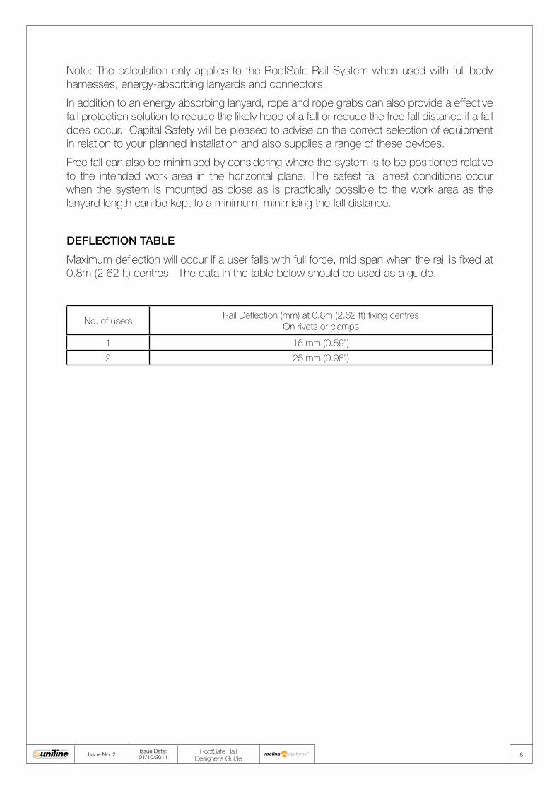
DEFLECTION TABLE
Maximum deflection will occur if a user falls with full force, mid span when the rail is fixed at 0.8m (2.62 ft) centres. The data in the table below should be used as a guide.
No. of usersRail Deflection (mm) at 0.8m (2.62 ft) fixing centres
On rivets or clamps
1 15 mm (0.59”)
2 25 mm (0.98”)

9Issue No: 2Issue Date: 01/10/2011
RoofSafe Rail Designer’s Guide
A
B
C
D
E
A
A) Inaccessible zone B) Zone for potential swing fall C) User D) Lanyard E) RoofSafe Rail System
A
A
A
B
C
D
E
A) Potential swing fall zoneB) User C) Lanyard D) RoofSafe Rail System E) Single point anchor
2.5 Swing fall Swing falls can be fatal when working near a gable end. Fig 6.0 shows a worker using a rope and grab at maximum extension near a gable end. In this case the flank length exceeds the ridge height so if the user falls they have inadequate clearance to ground level. Another risk is the slicing effect of the edge of the roof on the rope or lanyard as the user falls. This situation must be avoided. The fall distance can be limited by installing single point anchors, installing edge protection to the end elevation and by installing RoofSafe Rail inboard of the roof eaves.
Fig. 6.0
Fig. 6.1 Fig. 6.2
Fig 6.1 shows the potential swing fall area and the inaccessible zones. Fig 6.2 shows how the area of accessibility can be increased and swing fall potential limited by a single point anchor.
10Issue No: 2Issue Date: 01/10/2011
RoofSafe Rail Designer’s Guide
3. Site Assessment3.1 Reviewing the TaskOnly installers authorised by Capital Safety are allowed to install and service the RoofSafe Rail System.
SITE SURVEY
At the start of each project a site survey should be carried out to assess the type and location of the system required. This should be done from a position of safety. Accurate measurements should be taken to make sure that the system will fit the required area correctly. A consideration should be given to the roof type as this will effect the type of fixing which can be used. Special consideration should be given to systems where corners are required, as this will affect the position of the fixings and spreader plates.
During a site survey the following information should be gathered:
• Thepurposeofthesystem/tasktobeperformed.
• Themaximumnumberofpeoplethatwillbeusingthesystematanyonetime.
• Thestructurethesystemistobemountedto.
• Scaledrawingsofthestructureorbuilding(indigitalformatifavailable).
• Theexactpathofthesystem.
• Anyspecialrequirementsfromthearchitectorthecustomersuchas,aspecifictypeofbracket, or particular considerations for historical buildings.
• Theriskstotheinstallerssothatsuitableriskcontrolsduringinstallationcanbeplanned.
• Theriskstotheusergainingaccesstothesystem.
When seeking technical support on a specific job, the Capital Safety sales team will be able to help you more quickly if you have the above information available as a minimum.
DRAWINGS
Only accurate scale drawings provided either by the architect of the structure, or drawn from a comprehensive site survey should be used when detailing and specifying a RoofSafe Rail System, to prevent changes needing to be made by the installer on site when the system is fitted.
RISK ASSESSMENT/HAZARD ANALYSIS
A suitable and sufficient risk assessment should be produced in advance of any site access and/or installation work, to ensure that risks to health and safety can be properly identified. The appropriate control measures must be implemented to eliminate or mitigate any risks. Access, installation and risk mitigation must be pre considered, discussed and detailed within a ‘project’ method statement.

11Issue No: 2Issue Date: 01/10/2011
RoofSafe Rail Designer’s Guide
Where RoofSafe Rail lengths have to be cut and/or drilled on site always take adequate safety precautions. Only use tooling/fixtures that will ensure a clean perpendicular cut and/or accurately placed holes.
3.2 The Mounting StructureRoofSafe Rail can be fitted to a:
• Bulbtypestandingseamroof
• Foldedstandingseamroof
• Builtuproof
• Compositeroof
Where compatibility between the structure and the system can not be verified by either approval or a structural engineer, a tensile test must be performed on the structure in a controlled environment. The details of the system and test results should be checked by a structural engineer to ensure compatibility. The compatibility is normally proven by using a Hydrajaws pull tester (code 7241125, Safety Eyebolt Kit MK 2) to verify the pullout load for individual fasteners.
Later in the manual there are details of fasteners/anchors to suit your structure.
3.3 Gaining Access to the SystemThe entry point is defined as the point where the user can attach to the system. The exit point is defined as the point where the user can detach from the system. The entry point and the exit point can be at the same position. It is important to remember that the user is not fully protected from a fall until the carriage is fully engaged onto the system, the tamper proof/ plunger stop is fitted and the user is connected to the carriage. Where the carriage is permanently fitted to the system the user is not fully protected until the connection between the carriage, lanyard and harness is made.
In planning the configuration of the system, adequate consideration should always be given to the positioning of the rail with regards to the above. The entry point should always be in a safe area, i.e. free from fall hazards. Where this cannot be achieved, a secondary means of fall protection needs to be installed to give protection whilst bridging the gap between the access route and the RoofSafe Rail System. The same consideration needs to be made in respect to the exit point, should it be in a different position to the entry point.

12Issue No: 2Issue Date: 01/10/2011
RoofSafe Rail Designer’s Guide
3.4 Environmental Conditions
BIMETALLIC CORROSION
Bimetallic corrosion (or Galvanic Corrosion) is the accelerated corrosion of one metal placed in contact with a different more noble (less corroding) metal. It generally occurs around fixings such as nuts and bolts, rivets or welds in situations where different metals are in contact and can become wet. In the case of the RoofSafe Rail product stainless steel is more noble than 6000 series aluminium alloy, but the two metals are close to one another in the nobility table so corrosion is extremely unlikely. If any corrosion were to occur it would occur on the less noble material,in this case the aluminium rail. Capital Safety use Stainless Steel A4 70 fasteners where ever possible as they offer excellent corrosion resistance for the wide range of environments that we expose our systems to. “A4”signifies that the fastener is made from the corrosion resistant austenitic stainless steel.“70” relates to 1/10th of the tensile strength of the fastener. So a fastener with a rating of 70 has a tensile strength of 700 N/mm2.
ENVIRONMENTAL PERFORMANCE OF ROOFSAFE RAIL
RoofSafe Rail is extruded from 6000 series aluminium alloy. This grade of alloy is a high strength alloy containing magnesium, manganese and silicon. The 6000 series alloy has the highest strength and can be heat treated. The 6000 series alloys are used in applications such as buildings, structures, machinery and process equipment applications.
The addition of manganese assists in controlling the grain structure whilst the magnesium markedly increases the strength of aluminium without unduly decreasing the ductility. Capital Safety have the chosen to specify the heat treatment to the T6 condition. Alloys in T6 condition generally have the highest strength without sacrificing other properties which are required from the material in this application.
RoofSafe Rail is not coated as the 6000 series aluminium has excellent resistance to atmospheric corrosion (often called weathering) and in many outdoor applications, such alloys do not require shelter, protective coatings or maintenance. UniRail is also extruded from 6000 series aluminium alloy and is anodised as standard, as it is frequently used in more aggressive environments. Aluminium alloys of the 6000 series are resistant to corrosion by many natural waters. The more important factors controlling the corrosivity of natural waters to aluminium include water temperature, pH, and conductivity, availability of cathodic reactant, presence or absence of heavy metals, and the corrosion potentials and pitting potentials of the specific alloys.
The RoofSafe Rail will fit to a wide variety of roof types. Roofs vary greatly in their design, structure and material composition. The RoofSafe Rail is not coated as standard, but a powder coating can be specified to match a particular RAL colour or anodised to improve the corrosion resistance. If you have concerns about specifying RoofSafe in a hazardous or aggressive environments or on particular roof profile then contact Capital Safety for further assistance.

THE EFFECT OF TEMPERATURE ON ROOFSAFE RAIL
The coefficient of thermal expansion of 6000 series aluminium alloy is relatively high at 23x10-6/°C.
RoofSafe Rail is fixed at regular intervals to the seams or crowns of the roof so it does not have the freedom to expand and contract. A change of temperature causes the rail to move in all directions, therefore it is important to allow for a 2 - 3mm gap between joining rails where possible. The largest change will be seen on the longest length, ( i.e. the length of the rail at 3m) but as the rail is fixed in individual sections back the roof, it is not free to float and hence grow as a continuous length of free material would.
The effects of temperature variations could induce stress in the rail and subsequently the roof the rail is being fixed to. The worst case could be seen on a roof where the difference between the coefficient of thermal expansion is greatest.
If the rail was fitted onto a steel roof, the difference in dimensional change can be seen below:
A 3m length of RoofSafe rail exposed to temperature increase of 30° C will expand by:
30°C x 23 x 10-6 x 3m = 0.00207 m.( 2mm) (0.08”)
The equivalent expansion of the steel when exposed to a 30° C change:
30°C x 15 x 10-6 x 3m = 0.00135 m.( 1.35mm) ( 0.05”)
A difference in length of 0.65mm (0.025”)
For other coefficients of thermal expansion refer to the engineers reference table section 4.4.
In most cases the change in length will not be noticeable as the movement will be taken up in the clearance around fixings, movement of clamps and flex in the roof sheet.
If you are installing in a location which sees large temperature variations (over 30°C) in 24 hours and only one element of the roof or rail is exposed to the change then it is worth investigating an engineered solution which can accommodate this. Contact Capital Safety for help to develop a solution for your project.
The safe operating temperature range for the RoofSafe product is -50°C (-58°F) to 150°C (302°F) (excluding any rubber or plastic components). For specialist applications in extreme temperatures contact Capital Safety.
13Issue No: 2Issue Date: 01/10/2011
RoofSafe Rail Designer’s Guide

14Issue No: 2Issue Date: 01/10/2011
RoofSafe Rail Designer’s Guide
3.5 Environmental ImpactAs one the leading manufacturer’s of fall protection products Capital Safety are aware of the impact that our products and services have on the environment. Capital Safety are committed to understanding and communicating these impacts to our customers as part of the continuous development of our environmental policy.
The aluminium economy is a circular economy. Aluminium is 100% recyclable without any loss of its natural qualities. Recycling involves melting the scrap, a process that requires only five percent of the energy used to produce aluminium from ore. In addition, recycling of aluminium products only emits 5% of the greenhouse gases emitted in primary aluminium production.
The extrusion of RoofSafe Rail starts with aluminium alloy Ingots, these are cut into billets and then heated to extrusion temperature. Pressure is then applied to force billet through a die. Once the profile emerges it is then cooled via air or water. Extrusion allows for metal to be placed where it is needed most therefore maximising material use. Any waste aluminium is recycled. Remelting facilities are enclosed to monitor and contain gas emissions during the process.
3.6 Rescue PlanningThe Working at Height regulations requires the employer to make specific provisions for emergency planning. Work should be appropriately planned and previsions should be made for emergency situations. The need for rapid and appropriate response following a fall must not be ignored. Being suspended whilst unconscious for any length of time, in extreme scenarios lead to death, therefore it is important that rescue planning is taken seriously.
It is important to establish whether you are planning for a “rescue” or an “evacuation” as this can affect the equipment and training required. A rescue is usually the recovery of a casualty by another person. An evacuation is typically carried out by a trapped user to escape from a remote situation.
Having recognised the need for timely rescue and evacuation it is vital that adequate resources are in place for each work site. Resources should include rescue/evacuation equipment and personnel who have been trained to use the equipment. In addition to this personnel should receive first aid training to enable them to manage a victim who is unconscious or in medical distress.
For further information visit www.capitalsafety.com

15Issue No: 2Issue Date: 01/10/2011
RoofSafe Rail Designer’s Guide
When planning a rescue/evacuation the following should be addressed:
•Thesafetyofthepersoncarryingouttherescue
• Theanchorpointstobeusedfortherescueequipment
• Thesuitabilityoftheequipmentforthespecificrescue/evacuationscenario
•Themethodwhichwillbeusedtoattachthecasualty
• Thefallprotectionsystemwhichthecasualtywillbeusing
•Thedirectionthecasualtyneedstobemovedtogetthemtoapositionofsafety
• Theneedsofthecasualtyfollowingtherescue
•Thenumberofpeoplerequiredfortherescue
•Amethodforeffectivecommunicationbetweentherescuerandthecasualty
• Be aware of the dangers of prolonged exposure to suspension in harness and postrescue treatments.
When working at height a sensible strategy is to employ two workers for the task, so if one falls, the other can assist in the rescue, or can summon help. High visibility clothing, whistles and personal alarms are all items worthy of consideration. Before performing a rescue assess the following:
•Assessthesituationtomakesurethatarescueneedstobeperformed
•Alerttheemergencyservices
• Identifyanchoragepoints
• Identifywherethecasualtywillbemovedto
•Makesureallmembersoftherescueteamknowtheirrolewithintheprocedure
Most procedures will recommend that the emergency services are called and informed of the situation so the appropriate assistance can be mobilised. In many circumstances, particularly in metropolitan areas, such a response may be sufficient, however in remote/exposed situations the capability of the emergency services is limited. Operatives will require the competence, equipment and procedures to initiate rescue and evacuation independently.
In which case the following factors should be explored:
• ConsiderPersonalProtectiveEquipment,anchoragesandproceduresthatreduceshockloadings and fall distances.
• PrepositionorhaveavailableaccessequipmentsuchasMobileElevatedWorkPlatformsor platforms that will enable simple rescue and evacuation as required.
• Considertheuseofspecialistrescueandorevacuationdevices-onthebasisthattheywill be infrequently used, operated by non professional trained operators and should therefore be as ‘fail safe’ and technically simple as possible.
Capital Safety offer a range of rescue devices, contact Capital Safety for further details.

16Issue No: 2Issue Date: 01/10/2011
RoofSafe Rail Designer’s Guide
4. Designing Your System4.1 Specifying the SystemOnly installers authorised by Capital Safety are allowed to install and service the RoofSafe Rail System. The site assessment (section 3.0) in this manual should have answered the key questions to enable the design of the systems.
To avoid excess cutting and drilling operations, and to avoid rail wastage it is recommended that the full length of the rail sections are utilised wherever possible (3m, 118” lengths as standard). Once a system layout has been completed a list of materials can be complied. Pay particular attention to:
• SpreaderPlateMeasurements(allowingforclamp&crownwidths).
• Anglesofcorners.
• TypeandquantityofRivets/Clampstobeused.
• The number of carriages to allow for the users, a rescue strategy and/or suspendedaccess.
JOINING RAIL
We recommend that the full system is arranged on the roof prior to fixing in position (see installation instructions). The rail length and the position of the rail joins can then be located between the roof crowns/seams (See Fig 7). This applies to fall arrest, fall restraint and suspended access for joins and corners. Where possible the join in the rail should be located equally between the crowns/seams, thus reducing the cantilever effect on any one crown or seam.
Equal Distance
Seam/Crown
Rail Joint
Recommended 2 – 3mm expansion gap
Fig. 7
17Issue No: 2Issue Date: 01/10/2011
RoofSafe Rail Designer’s Guide
CLAMPS & RIVETS
A key consideration in specifying the system lies in the holding down force of each section of the rail. In calculating the holding down force we assume that the full force of the fall is applied to one rail length (3m,118” ). Consider the number of rivets or clamps that are required on a given profile in tension and shear. The tensile values you use should be based on the pull out load of the rivet or the pull off load of the clamp. On most roof sheets it is the roof that will fail before the clamp or rivet. Pull off loads for the clamps on given profiles are featured in the reference section within this manual.
The rivet breaking strength is detailed on the datasheet. Rivet pull out values on specific roof sheets are not freely available so pull out testing is often required to determine the strength of the roof sheet. Our typical system layout for trapezoidal roofs is based on testing of the rivet on a composite panel with a 0.4mm (0.016””) steel outer skin.
A 7.7mm Bulb tite rivet pulls out of this panel at 2kN (450 lbf) . The 7.7mm bulb tite rivet should hold a minimum of 2kN in a given roof sheet. Based on this result our typical trapezoidal system has a pull of load of 28kN (6,295 lbf). (14 rivets on a 3m length) x 2 kN = 28kN. A 3m length must hold a minimum tensile pull off force of 24kN (5,395 lbf) per rail length (3m), twice the maximum load seen when two users fall on the system generating a total force of 12kN (2,698 lbf). When creating a layout refer to our typical layouts in the Technical Datasheet Pack. You must follow the clamp and rivet configurations to ensure the system meets the requirements detailed above.
ENVIRONMENT
Due consideration should be given to any localised environmental factors that may affect the performance of the system or the requirements for inspection. Factors may include, but are not limited to: extremes of temperature, exposure to chemicals or fumes which may cause or accelerate corrosion, possibility of vibration or impacts from other equipment etc.
ORIENTATION
RoofSafe Rail is designed to be attached to the outer skin of a trapezoidal built up or composite roof or a bulb type / folded standing seam roof. The Installation of the System in a non horizontal attitude (e.g. on an incline) is NOT permitted for falling purposes ( e.g. in those cases where it is essential that the carriage automatically locks onto the rail.) If the site requires the system to be installed in a non horizontal attitude (e.g. to gain access to the roof ridge please contact Capital Safety.)
It is important to take into consideration fall factors, the type of work that is being carried out and where the worker needs to be positioned to carry out the work safely. The system should be mounted in an orientation that gives the best possible protection without hindering the users ability to work.
18Issue No: 2Issue Date: 01/10/2011
RoofSafe Rail Designer’s Guide
INSPECTION REQUIREMENTS
The frequency and type of inspection required can affect the specification of the system. Under normal conditions the system must be inspected every 12 months in accordance with Capital Safety’s Maintenance Check Sheet. The inspection should be conducted by an approved Capital Safety installer. A system which will be used for suspended access should be inspected every 6 months or in accordance with local government regulations. The same inspection period applies for systems which are subjected to a highly corrosive environment. Where access to the system for maintenance is limited you may need to use an elevated work platform.
STRENGTH OF THE SUPPORTING STRUCTURE
The strength of the supporting structure needs to be assessed by a structural engineer before the system is installed, it is important that the strength and the number of fixings used are strong enough to support the loads transferred back to the structure.

19Issue No: 2Issue Date: 01/10/2011
RoofSafe Rail Designer’s Guide
A
F
4.2 Forces on the systemThe RoofSafe System complies with the EN795 class D standard. It has also been tested extensively by Capital Safety. We find that a rail system reacts differently from a traditional cable system. A cable system transfers high loads (Up a maximum of 20kN (4,496lbf)) to the end anchors in the event of a dynamic load being applied.
The broad base of RoofSafe Rail prevents it bending in the same way as the UniRail product. This means it reacts like a beam, sharing the load between all fixings directly attached to that particular section of rail. This is a great advantage on roof sheets which can be only 0.4mm thick.
Users of the system MUST all use Energy Absorbing Lanyards which conform to the appropriate national standard. The lanyard has to limit the load on the user to less than 6kN (1,350lbf). A load of 12kN (2,698lbf) could be applied if two users were to fall at exactly the same time and their arrest force was transferred at the same time. The load of 12kN (2,698lbf) is equally shared between the fixings securing the rail onto the roof sheet. In most scenarios this is expressed as shear force on the fastener.
Figure 8 shows a length of RoofSafe Rail fixed with standing seam clamps. There is minimal deformation seen in the rail when a dynamic load is applied at point A. When a static load of 12kN (2,698lbf) is applied the rail will elastically deform typically no more than 25mm (1”) across its length. Typically for the testing performed all of the peak energy generated in a dynamic fall has been absorbed within 3/10th of a second.
Fig. 8

20Issue No: 2Issue Date: 01/10/2011
RoofSafe Rail Designer’s Guide
As part of the ongoing development of the RoofSafe Rail product we are now performing FEA (Finite Element Analysis). The FEA highlights the stress levels in the product. This series of images show the stresses at the clamps when a static load is applied. It is worth considering that the dynamic load only applies an instantaneous load. The stress levels highlight the intensity of the stress they do NOT indicate failure, they indicate where failure may occur when more force is applied.
Fig 9 shows a section through the rail and clamps at position A. The Von Mises forces show the internal stress from the horizontal shear load which is acting across the rail and brackets. The stress level is slightly higher on the front fastener (fastener on the left) as it has a larger contact zone than the fastener on the right.)
Fig 10 highlights the stress distribution as a tensile load. Note the higher stress seen in the rear fastener (fastener on the right) as the overturning moment attempts to pull the fastener from the clamp.
Fig. 9
Fig. 10

21Issue No: 2Issue Date: 01/10/2011
RoofSafe Rail Designer’s Guide
STRESSES ON THE CARRIAGE AT 6KN
This FEA section shows the stress levels on the carriage at a load of 6kN (1,350lbf). The most noticeable point is the comparative stress level in the rail relative to the stress on the carriage. The stress distribution shows the rail is bending with an axial tensile force. The load applied to the rail by the carriage is mid span, between clamps at 0.8m (2.62 ft) centres. The rail is undergoing simple bending therefore the tensile and compressive forces are of similar magnitude.
In the carriage the high stress level is again found at the local area of load transfer from one component to another (Fig 11). The constraint holding the wheel to the rail and in turn the shackle shows a high level of stress. This stress concentration will reduce when the contact area increases due to elastic and plastic deformation of the components.
This confirms the physical test data gathered by Capital Safety on this system.
Fig. 11

22Issue No: 2Issue Date: 01/10/2011
RoofSafe Rail Designer’s Guide
4.4 Engineer’s Reference Table
6000 Series aluminium alloy Rail Section Metric Imperial (US)
Density 2.70 g/cc 0.0975 lb/in³
0.2% Proof Stress 255 MPa (minimum) 16.5 tonne / in2
Ultimate Tensile Strength 295 MPa (minimum) 19.1 tonne / in2
Elongation 10% Minimum 10% Minimum
Coefficient of Thermal Expansion for Aluminium 23 x 10-6 m/°C 12.3 x 10⁻⁶
in/°F
Cross Section Area 902.39mm2 0.774 in2
Moment of Inertia Ixx = 128523mm4
Iyy = 1038581mm4
0.309in4
2.4966in4
Elastic Modulus 70GPa 1.46x10⁹ lb/f2
Poisson Ratio 0.35
Coefficient of thermal linear expansion Aluminium 20 x 10-6 K-1
Concrete 12 x 10-6 K-1
Steel 15-16 x 10-6 K-1
Zinc 31 x 10-6 K-1
Brass 18 x 10-6 K-1
23Issue No: 2Issue Date: 01/10/2011
RoofSafe Rail Designer’s Guide
5. Personal Protective Equipment
All Personal Protective Equipment (PPE) used in conjunction with the RoofSafe Systems should carry the following markings:
• CEmarkorappropriatenationalcertification.
• Dateofmanufacture.
• Standardthatithasbeenmanufacturedto.
Any harness to be used should be a full body harness. All lanyards used must have an energy/shock absorbers.
Slings to be used with the system or as part of a work access provision, must be suitable for use as Personal Protective Equipment. Only slings made from man made fibres such as Polyamide or Polyester webbing are suitable for this application, and must have a minimum breaking strength of 22kN (4,945.8 lbf).
Slings ropes and lanyards should never be connected directly to each other as movement can cause excessive wear, a suitable connector such as a locking Karabiner should be used.

24Issue No: 2Issue Date: 01/10/2011
RoofSafe Rail Designer’s Guide
6. System Maintenance & InspectionThe following instructions cover the servicing procedures for the RoofSafe Rail System. They exclude the servicing requirements for anchors and Personal Protective Equipment such as harnesses, energy-absorbing lanyards and connectors.
The table below sets out occasions when servicing may be required and the type and content of service needed.
Type of servicing required
Routine reasons (e.g. annual service under BS EN 365) A
Customer request (unscheduled) A
A defect or damage has arisen in use B
The system has sustained a fall arrest loading C
TYPE “A” SERVICING
A.1 Removal of the Carriage from SystemIn installations which have the tamper proof end stops, the carriage remains mounted to the rail at all times. To gain access to the RoofSafe Rail System use a spare carriage or a separate means of fall protection if necessary. Remove the carriages from the system by removing the screws securing the tamper proof end stops.
A.2 Cleaning If any part or component of the system needs cleaning prior to examination, proceed as follows:
• Carriage: To clean, immerse the carriage in a mix of hot water / mild detergent. Thecarriage can then be rinsed and dried using a clean non-abrasive cloth. Solvents and acidic based products must not be used for cleaning.
• Rail:Thecarriagecleaningprocedurecanalsobeusedtocleantherail.Afibrebrushcanbe used to remove dirt, etc. Never use wire brushes and never use solvents.
A.3 Examination of the Carriage • Ensure that the connection between the energy-absorbing lanyard and the carriage
shackle is secure.
• Ensurethatthecarriageshackleisfreetopivotandthatitssecuringpiniscentrallylockedon the inside face.
• Ensurethatthefourwheelsareinplace,undamagedandareabletorotate.Checkthateach has its securing clip in place and that the wheel axle is not loose.
• Ensurethattheknurledknobisunscrewedsufficientlytopreventarestrictionontherail.Check that the securing clip is in place.

25Issue No: 2Issue Date: 01/10/2011
RoofSafe Rail Designer’s Guide
• Checkthecarriageforobviousdamage,suchascracks,heavyindentationsorseverecorrosion. Remove and dirt from the inside face and bearing wheels. Reject the carriage is it appears unserviceable.
• Iftheshacklerequireslubrication,applyalightwaterrepellentlubricantsparingly;avoidcontact with the carriage wheels, lanyard and harness. Do not use any type of lubricant on the carriage wheels.
A.4 Preparation to the Examine Remainder of System Depending upon the type of system, examine the tamper proof stops/plunger stops for obvious defects such as cracks or heavy corrosion.
• TamperProofStop:Holdthetamperproofstopandgiveitasharptugtoensurethatitissecure. Also check with a torque wrench that it is tightened to 15Nm (11.1 lbf).
• PlungerStop:Ontheplungerstopensurethattheplungeroperatessatisfactorily.rejectdefective articles.
Put on the safety harness to be used with the system in accordance with the manufacturers’ instructions. Connect one of the energy absorbing lanyards to the attachment point of the harness and the other to the carriage.
A.5 Examination of Remainder of System Walk along the RoofSafe Rail System and ensure that the carriage glides along the rail without being impeded. Check that the system components are not defective. Ensure that all joints are complete with fittings intact. In particular:
• Rail:Checkforanyobviousdamagesuchascracks,heavyindentations,deformationorsevere corrosion. Deformation and indentations may be evidence of a fall.
• Check for chemical contamination (e.g. discolouration) and heat damage (e.g. weldspatters). Particular attention should be paid to joints.
• Ensurethattheothersystemstopisfirmlyinplaceandthatitpreventsthecarriagefromcoming off the rail unintentionally. Check that the moulded rail end covers are not missing or split.
• Checkthesecurityof therailat regular intervalsbygiving itasharptug,payparticularattention to joints. Look for external damage to the supporting structure, e.g. roof seams.
• Checkthatalljointsareinlinewiththeirmatingrailsectionandthatthecarriagecannotcome off at this point.
26Issue No: 2Issue Date: 01/10/2011
RoofSafe Rail Designer’s Guide
• Checkallfixingswhichanchortherailtothestructureforobviousdamageandensurethatrivet heads are not protruding, clamp bolts are tightened and grub screws are torqued to 15Nm. Also check rails joints are secure. If a structural fixing is in question then remove and replace.
Any defective parts should be marked and replaced as necessary. Refer to TYPE “B” Service instructions for replacing rail components. Record that the servicing has been carried out on the inspection/servicing sheet.
IMPORTANT NOTE: IF IT IS SUSPECTED THAT A FALL ARREST
HAS OCCURRED, CARRY OUT A TYPE “C” SERVICE
TYPE “B” SERVICING
Once the defect has been identified it must be assessed against the rejection criteria under the Type “A” Service. Replace defective carriages as necessary. Replace rail sections/components in accordance with the instructions below.
B.1 Damaged Rail sections
Determine the shortest distance to an end-rail assembly from the defective rail section. Carefully drill out the rivets in all the rail sections covering this length, or remove clamps. Remove the rail sections in the same order as originally riveted/clamped so that after the defective rail section has been replaced they can to be secured in the correct sequence.
Rivet/clamp a new rail section in place following the original sequence in accordance with the Installation Instructions. If the rail section is part of a joint, replace spigot pins with new ones
After rectifying the defect, the whole system is to be checked in accordance with the Type “A” Service, as there may be other defects unrelated to the incident.
Record that the servicing has been carried out on the inspection/servicing sheet.
WARNING !THE FOLLOWING PROCEDURES ARE FOR REPLACING
DAMAGED OR DEFECTIVE COMPONENTS FOLLOWING NOTIFICATION THAT THE SYSTEM IS UNSERVICEABLE.
DO NOT ATTACH TO THE SYSTEM UNDER THESE CIRCUMSTANCES.
USE A SEPARATE SAFE MEANS OF FALL-PROTECTION
27Issue No: 2Issue Date: 01/10/2011
RoofSafe Rail Designer’s Guide
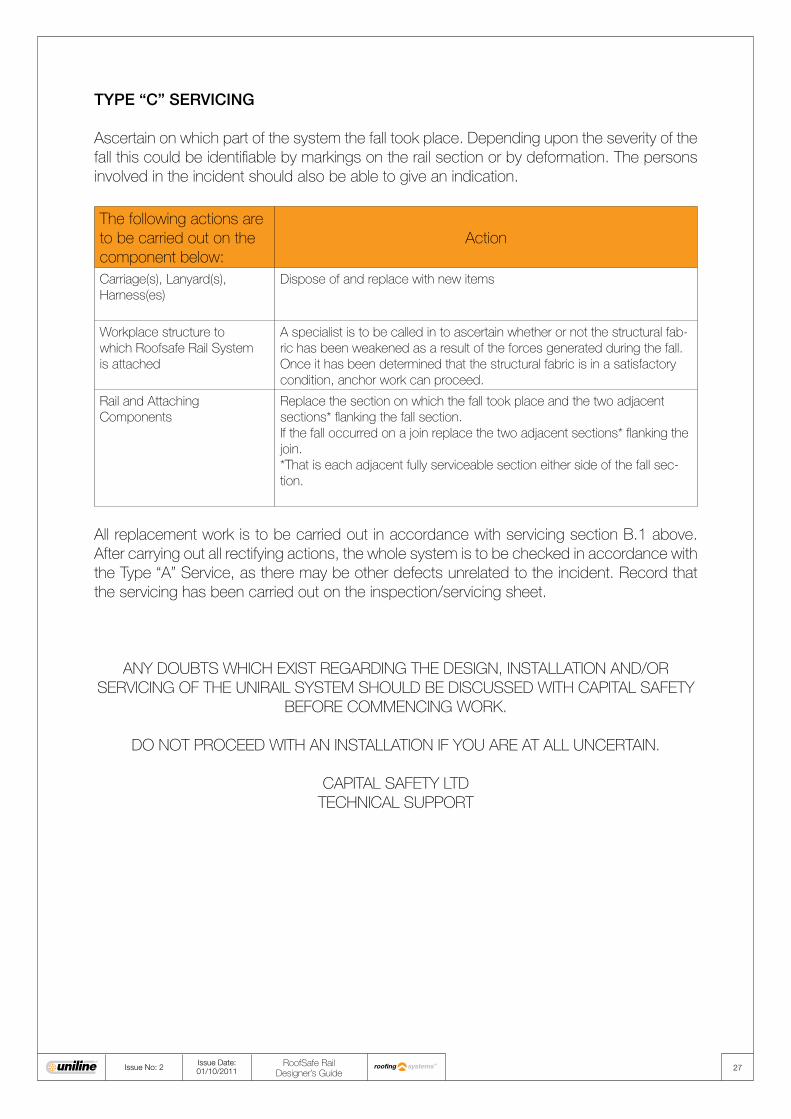
TYPE “C” SERVICING
Ascertain on which part of the system the fall took place. Depending upon the severity of the fall this could be identifiable by markings on the rail section or by deformation. The persons involved in the incident should also be able to give an indication.
The following actions are to be carried out on the component below:
Action
Carriage(s), Lanyard(s), Harness(es)
Dispose of and replace with new items
Workplace structure to which Roofsafe Rail System is attached
A specialist is to be called in to ascertain whether or not the structural fab-ric has been weakened as a result of the forces generated during the fall. Once it has been determined that the structural fabric is in a satisfactory condition, anchor work can proceed.
Rail and Attaching Components
Replace the section on which the fall took place and the two adjacent sections* flanking the fall section. If the fall occurred on a join replace the two adjacent sections* flanking the join. *That is each adjacent fully serviceable section either side of the fall sec-tion.
All replacement work is to be carried out in accordance with servicing section B.1 above. After carrying out all rectifying actions, the whole system is to be checked in accordance with the Type “A” Service, as there may be other defects unrelated to the incident. Record that the servicing has been carried out on the inspection/servicing sheet.
ANY DOUBTS WHICH ExIST REGARDING THE DESIGN, INSTALLATION AND/OR SERVICING OF THE UNIRAIL SYSTEM SHOULD BE DISCUSSED WITH CAPITAL SAFETY
BEFORE COMMENCING WORK.
DO NOT PROCEED WITH AN INSTALLATION IF YOU ARE AT ALL UNCERTAIN.
CAPITAL SAFETY LTD TECHNICAL SUPPORT

28Issue No: 2Issue Date: 01/10/2011
RoofSafe Rail Designer’s Guide
7. Reference Documents7.1 Abbreviations and Definitions
The following is a list of terms and their meanings as used in this publication (Further standards are listed in section 7.2 of this guide):
BS EN 795 The European Standard for protection against falls from a height concerning anchor device requirements and testing
BS EN 354 The European Standard for protection against falls from a height concerning lanyards
BS EN 355 The European Standard for protection against falls from a height concerning energy absorbers
BS EN 361 The European Standard for protection against falls from a height concerning full body harnesses
BS EN 362 The European Standard for protection against falls from a height concerning connectors
BS EN 363 The European Standard for protection against falls from a height concerning fall arrest systems
BS EN 365 The European Standard for protection against falls from a height concerning instructions for use and markings
BS 7883 Code of Practice for the application and use of anchor devices conforming to BS EN 795
89/686/EEC EC Directive relating to Personal Protective Equipment design and test
SI 3139 Statutory Instrument 3139 The Personal Protective Equipment (EC Directive) Regulations 1992 - the transposition of 89/686/EEC into UK National Law
OHSA 1926.502M (d) (15) (i) Fall protection systems criteria and practices.
29Issue No: 2Issue Date: 01/10/2011
RoofSafe Rail Designer’s Guide
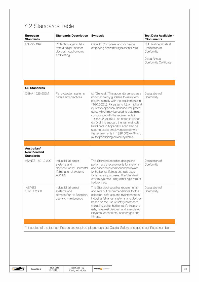
7.2 Standards TableEuropean Standards
Standards Description Synopsis Test Data Available */Documents
EN 795:1996 Protection against falls from a height- anchor devices- requirements and testing
Class D: Comprises anchor device employing horizontal rigid anchor rails
NEL Test certificate & Declaration of Conformity
Dekra Annual Conformity Certificate
US Standards
OSHA 1926.502M Fall protection systems criteria and practices.
(a) “General.” This appendix serves as a non-mandatory guideline to assist em-ployers comply with the requirements in 1926.502(d). Paragraphs (b), (c), (d) and (e) of this Appendix describe test proce-dures which may be used to determine compliance with the requirements in 1926.502 (d)(15) (i). As noted in Appen-dix D of this subpart, the test methods listed here in Appendix C can also be used to assist employers comply with the requirements in 1926.502(e) (3) and (4) for positioning device systems.
Declaration of Conformity
Australian/New Zealand Standards
AS/NZS 1891.2.2001 Industrial fall-arrest systems anddevices Part 2: Horizontal lifeline and rail systems AS/NZS
This Standard specifies design and performance requirements for systems and associated component hardware for horizontal lifelines and rails used for fall-arrest purposes. The Standard covers systems using either rigid rails or flexible lines.
Declaration of Conformity
AS/NZS 1891.4.2000
Industrial fall-arrest systems anddevices Part 4: Selection, use and maintenance
This Standard specifies requirements and sets out recommendations for the selection, safe use and maintenance of industrial fall-arrest systems and devices based on the use of safety harnesses (including belts), horizontal life lines and rails, fall-arrest devices, and associated lanyards, connectors, anchorages and fittings...
Declaration of Conformity
* If copies of the test certificates are required please contact Capital Safety and quote certificate number.

UniRail Carriage7241006www.capitalsafety.com
EN795:1996 Class DOSHA CompliantAS/NZS1891.2
3
2
4
5
6
Min Ground Clearance (m) / Min. vrije valruimte (m) / Distancia minima hasta el suelo (m) / Mindestabstand zum Boden (m) / Hauteur libre minimale (m) / Altura mínima livre (mt) / Distanza libera minima da terra (m) / Min. höjd ovanför marken
Installation Date / Installatiedatum / Fecha de instalación / Montagedatum / Date d'installation / Data da instalação / Data installazione / Installationsdatum
Installed By / Geïnstalleerd door / Instalado Por / Montiert durch / Installateur / Instalado por / Installato da / Installerad av
Contact Number / Contactnr. / Tel. de contacto / Kontakttelefon / Téléphone / Nº de Contacto / Numero contatto / Kontaktnummer
Next Service Date / Datum volgende keuring / Próxima fecha de revisión / Termin der nächsten Wartung / Prochaine date d’entretien / Data da próxima Inspecção / Data prossima manutenzione / Nästa servicedatum
System Serial No / Serienummer / Número de serie del sistema / Seriennummer des Systems / Numéro de série / Nº de série do sistema / N. di serie sistema / Systemets serienr.
Max Users Per Span / Max. aantal gebruikers per overspanning / Máximo de usuarios por vano / Höchstzahl der Benutzer pro Spannweite / Nombre maximal d’utilisateurs par portée / Nº máximo de utilizadores por vão / N. utenti max. per sezione / Max. användare per skena
Max Users Per System / Max. aantal gebruikers per systeem / Máximo de usuarios por sistema / Maximale Benutzer pro System / Nombre maximal d’utilisateurs par système / Nº máximo de utilizadores por linha / N. utenti max. per sistema / Max. användare per system
www.capitalsafety.com
EN795:1996 Class DOSHA COMPLIANT
AS/NZS 1891.2 & 1891.4
Use Energy Absorbing Lanyards / Gebruik energie-absorberende verbindingslijnen / Utilice acolladores de absorción de energía / Verwenden Sie falldämpfende Sicherheits-/Anschlagseile / Utilisez des longes à absorption d’énergie / Usar cordas com amortecedor de energia / Utilizzare funi ad assorbimento d’energia / Använd energiupptagande taljerep
rail
rail
1
3
2
4
5
6
3
2
45
1
3
2
4
5
1
1
1
1
30Issue No: 2Issue Date: 01/10/2011
RoofSafe Rail Designer’s Guide
7.3 Markings Explained
Standards to which system conforms.Read Instructions for use
Web Address
Corporate logo
System information to be filled inby installer
Standards to which the system conforms; EN 795: 1996 Class D, OSHA Compliant and AS/NZS1891.2Protection against falls from a height-Anchor devices.
Part code and description
Read Instruction for use
Web Address
Corporate logo
Carriage Sticker
System Tag
Each Component is either marked with a batch number or given a unique GRN number to enable traceability of parts.
Component Marks
Brand Family

www.capitalsafety.euwww.unilinesafety.com
Worldwide Locations UK5a Merse RoadNorth Moons MoatRedditch, WorcestershireB98 9HLUK
t: +44 (0) 1527 548 000f: +44 (0) 1527 591 000
EUROPE, MIDDLE EAST & AFRICALe Broc CenterZ.I. 1re Avenue – BP1506511 Carros Le Broc CedexFRANCE
t: +33 (0)4 97 10 00 10f: +33 (0)4 93 08 79 70
USA3833 SALA WayRed WingMN 55066USA
freephone: 800 328 6146t: +1 (651) 388 8282f: +1 (651) 388 5065
CANADA260 Export BoulevardMississaugaOntario L5S 1Y9CANADA
freephone: 800 387 7484t: +1 (905) 795 9333f: 888 387 7484
AUSTRALIA & NEW ZEALAND95 Derby Street Silverwater NSW 2128 AUSTRALIA
freephone: 1800 245 002 (AUS)freephone: 0800 212 505 (NZ)t: +61 2 8753 7600f: +61 2 8753 7603
ASIANo 6 Tuas Avenue 18638892 SINGAPORE
t: +(65) 65587758f: +(65) 65587058
Capital Safety Group, through our Uniline brand is the global market leader in the design and manufacture of engineered fall protection systems. Through a combination of expert knowledge and practical experience, we can help our customers reduce risk and increase safety when working at height.
Our comprehensive Uniline range of products offers fully compliant, practical solutions for structures of all types, in all industries. Our ethos of delivering quality, service, training and support for our customers has earned Uniline a deserved reputation for excellence around the world.
Operating through specialist safety companies globally, Uniline provides local support and installation services to meet the specifi c safety objectives of all our customers.
local distributor/systems integrator
If you need a safety solution for roof access during maintenance and inspection tasks, then look no further than Uniline’s Roofi ng product range. Our products, including roof anchors, horizontal lifelines & horizontal rail systems offer comprehensive protection for workers on all types of roofs.
The products in our Horizontal systems range are some of the best know brands in fall protection safety. The versatility of these products combined with Uniline’s expertise in fall protection ensures we can solve even the most complex of height safety problems in industry, construction, façade access and for all manner of building maintenance and inspection tasks.
The best vertical fall protection systems in the world won’t let you down. The extensive development of this range of products for vertical structures including masts, towers, pylons, wind turbines, silos, bridges and chimney stacks ensures customers will enjoy the safest and most functional climbing experience possible.
A unique range of custom access products for challenging fall protection situations in transport and industry. These solutions are structurally analysed and designed to our customers exact needs and specifi cations.