designer’s reference handbook paralleling and protection
TRANSCRIPT
DEI
F A
/S
Paralleling and Protection Unit/GS Multi-line 2 4189340354I SW version 2.4X.X
Designer’s Reference Handbook
• Functional description • Display unit and menu structure
• PI controller
• Procedure for parameter setup
• Parameter setup
DEIF A/S, Frisenborgvej 33 Tel.: +45 9614 9614, Fax: +45 9614 9615 DK-7800 Skive, Denmark E-mail: [email protected], URL: www.deif.com

PPU Designer’s Reference Handbook
DEIF A/S Page 2 of 113
Table of contents
1. ABOUT THIS DOCUMENT ................................................................................................4 GENERAL PURPOSE......................................................................................................................4 INTENDED USERS..........................................................................................................................4 CONTENTS/OVERALL STRUCTURE..................................................................................................4
2. WARNINGS AND LEGAL INFORMATION........................................................................6 LEGAL INFORMATION AND RESPONSIBILITY.....................................................................................6 ELECTROSTATIC DISCHARGE AWARENESS .....................................................................................6 SAFETY ISSUES ............................................................................................................................6 DEFINITIONS ................................................................................................................................6
3. GENERAL PRODUCT INFORMATION .............................................................................7 INTRODUCTION .............................................................................................................................7 TYPE OF PRODUCT .......................................................................................................................7 OPTIONS......................................................................................................................................7 PC UTILITY SOFTWARE WARNING ..................................................................................................7
4. FUNCTIONAL DESCRIPTION ...........................................................................................8 STANDARD FUNCTIONS .................................................................................................................8 TERMINAL STRIP OVERVIEW ..........................................................................................................9 APPLICATIONS............................................................................................................................12 MEASUREMENT SYSTEMS ...........................................................................................................16 SINGLE DIAGRAMS......................................................................................................................18 SEQUENCES...............................................................................................................................22
5. DISPLAY UNIT AND MENU STRUCTURE .....................................................................24 DISPLAY UNIT .............................................................................................................................24 MENU STRUCTURE......................................................................................................................28 PASSWORD................................................................................................................................36
6. ADDITIONAL FUNCTIONS..............................................................................................37 LANGUAGE SELECTION................................................................................................................37 ALARM FUNCTION .......................................................................................................................38 SERVICE MENU...........................................................................................................................40 EVENT LOG ................................................................................................................................40 COUNTERS.................................................................................................................................42 KWH/KVARH COUNTERS.............................................................................................................43 SELF CHECK...............................................................................................................................43 TEXT IN STATUS LINE ..................................................................................................................43 DIGITAL INPUT CONFIGURATION...................................................................................................45 PARAMETER SHIFTING ................................................................................................................51 GENERAL FAILURE......................................................................................................................53 REGULATION FAILURE.................................................................................................................53 INHIBIT.......................................................................................................................................54 START/STOP NEXT GENERATOR...................................................................................................59 SETPOINT SELECTION .................................................................................................................62 EXTERNAL ANALOGUE SETPOINT .................................................................................................64 LOAD SHARING ...........................................................................................................................65 MODES ACTIVE...........................................................................................................................68 SYNCHRONISING WINDOW...........................................................................................................69 RELAY SETUP.............................................................................................................................71 HORN OUTPUT............................................................................................................................71 TRIP CHARACTERISTICS ..............................................................................................................72 GSM COMMUNICATION ...............................................................................................................74
PPU Designer’s Reference Handbook
DEIF A/S Page 3 of 113
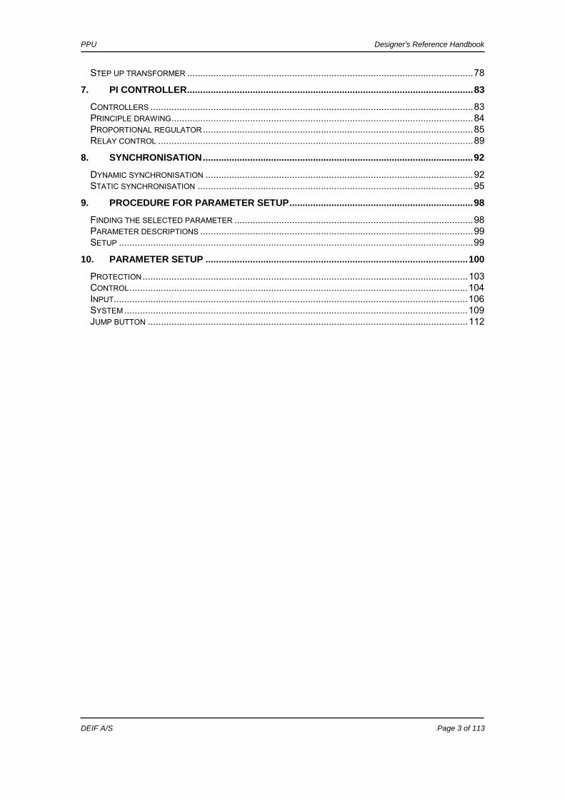
STEP UP TRANSFORMER .............................................................................................................78 7. PI CONTROLLER.............................................................................................................83
CONTROLLERS ...........................................................................................................................83 PRINCIPLE DRAWING...................................................................................................................84 PROPORTIONAL REGULATOR.......................................................................................................85 RELAY CONTROL ........................................................................................................................89
8. SYNCHRONISATION.......................................................................................................92 DYNAMIC SYNCHRONISATION ......................................................................................................92 STATIC SYNCHRONISATION .........................................................................................................95
9. PROCEDURE FOR PARAMETER SETUP......................................................................98 FINDING THE SELECTED PARAMETER ...........................................................................................98 PARAMETER DESCRIPTIONS ........................................................................................................99 SETUP .......................................................................................................................................99
10. PARAMETER SETUP ....................................................................................................100 PROTECTION............................................................................................................................103 CONTROL.................................................................................................................................104 INPUT.......................................................................................................................................106 SYSTEM...................................................................................................................................109 JUMP BUTTON ..........................................................................................................................112
PPU Designer’s Reference Handbook
DEIF A/S Page 4 of 113
1. About this document This chapter includes general user information about this handbook concerning the general purpose, the intended users and the overall contents and structure.
General purpose This document is the Designer’s Reference Handbook for DEIF’s Paralleling and Protection Unit, the PPU. The document mainly includes functional descriptions, presentation of display unit and menu structure, information about the PI-controller, the procedure for parameter setup and complete standard parameter lists. The general purpose of the Designer’s Reference Handbook is to provide useful overall information about the functionality of the unit and its applications. This handbook also offers the user the information he needs in order to successfully set up the parameters needed in his specific application.
Intended users The handbook is mainly intended for the person responsible for the unit parameter setup. In most cases, this would be a panel builder designer. Naturally, other users might also find useful information in the handbook.
Contents/overall structure The Designer’s Reference Handbook is divided into chapters and in order to make the structure of the document simple and easy to use, each chapter will begin from the top of a new page. The following will outline the contents of each of the chapters.
About this document This first chapter includes general information about this handbook as a document. It deals with the general purpose and the intended users of the Designer’s Reference Handbook. Furthermore, it outlines the overall contents and structure of the document.
Warnings and legal information The second chapter includes information about general legal issues and safety precautions relevant in the handling of DEIF products. Furthermore, this chapter will introduce note and warning symbols, which will be used throughout the handbook.
General product information The third chapter will deal with the unit in general and its place in the DEIF product range.
Functional descriptions This chapter will include functional descriptions of the standard functions as well as illustrations of relevant application types. Flowcharts and single-line representations will be used in order to simplify the information.
Please make sure to read this handbook before working with the Multi-line 2 controller and the gen-set to be controlled. Failure to do this could result in human injury or damage to the equipment.

PPU Designer’s Reference Handbook
DEIF A/S Page 5 of 113
Display unit and menu structure This chapter deals with the display unit including the push-button and LED functions. In addition, the unit menu structure will be presented. Furthermore, the selection of unit mode and password will be illustrated.
Additional functions This chapter describes the additional functions of the unit.
PI-controller This chapter offers information about the PI-controller in the form of principle drawings and descriptions.
Synchronising This chapter contains detailed information about the unit’s dynamic and static synchronisation.
Procedure for parameter setup This chapter deals with the procedure to be followed when the parameters are set up or changed. By means of various illustrations, this chapter will guide the user through the procedure for parameter setup step by step.
Parameter list This chapter includes a complete standard parameter list for setup. Therefore, this chapter is to be used for reference when information about specific parameters is needed.
PPU Designer’s Reference Handbook
DEIF A/S Page 6 of 113
2. Warnings and legal information This chapter includes important information about general legal issues relevant in the handling of DEIF products. Furthermore, some overall safety precautions will be introduced and recommended. Finally, the highlighted notes and warnings, which will be used throughout this handbook, are presented.
Legal information and responsibility DEIF takes no responsibility for installation or operation of the generator set. If there is any doubt about how to install or operate the generator set controlled by the unit, the company responsible for the installation or the operation of the set must be contacted.
Electrostatic discharge awareness Sufficient care must be taken to protect the terminals against static discharges during the installation. Once the unit is installed and connected, these precautions are no longer necessary.
Safety issues Installing the unit implies work with dangerous currents and voltages. Therefore, the installation should only be carried out by authorised personnel who understand the risks involved in working with live electrical equipment.
Definitions Throughout this document a number of notes and warnings will be presented. To ensure that these are noticed, they will be highlighted in order to separate them from the general text.
Notes
Warnings
The notes provide general information which will be helpful for the reader to bear in mind.
The warnings indicate a potentially dangerous situation which could result in death, personal injury or damaged equipment, if certain guidelines are not followed.
Be aware of the hazardous live currents and voltages. Do not touch any AC measurement inputs as this could lead to injury or death.
The units are not to be opened by unauthorised personnel. If opened anyway, the warranty will be lost.
PPU Designer’s Reference Handbook
DEIF A/S Page 7 of 113
3. General product information This chapter will deal with the unit in general and its place in the DEIF product range.
Introduction The PPU is part of the DEIF Multi-line 2 product family. Multi-line 2 is a complete range of multi-function generator protection and control products integrating all the functions you need into one compact and attractive solution.
Type of product The Paralleling and Protection Unit is a micro-processor based control unit containing all necessary functions for protection and control of a generator. It contains all necessary 3-phase measuring circuits, and all values and alarms are presented on the LCD display.
Options The Multi-line 2 product range consists of different basic versions which can be supplemented with the flexible options needed to provide the optimum solution. The options cover e.g. various protections for generator, busbar and mains, voltage/VAr/PF control, various outputs, serial communication, etc.
PC utility software warning
It is possible to remote control the gen-set from the PC utility software M-Vision or the Proface Display Unit by use of a modem. To avoid personal injury, make sure that it is safe to remote control the gen-set.
A full options list is included in the data sheet, document no. 4921240313.
PPU Designer’s Reference Handbook
DEIF A/S Page 8 of 113
4. Functional description This chapter includes functional descriptions of standard functions as well as illustrations of the relevant application types. Flowcharts and single-line diagrams will be used in order to simplify the information.
Standard functions In the following paragraphs the standard functions are listed.
Applications:
Stand-alone • Parallel with other gen-sets • Parallel with the mains
Control functions • Synchronising • Power and frequency controls
Operation modes • Fixed frequency • Fixed power (base load) • Droop • Load sharing
Protections (ANSI) • Reverse power (32) • Overcurrent, 2 levels (51) • Overcurrent, 1 level (51) • Display
Separate mounting • Status texts • Easy readable • Programming
Measuring system • 3-phase true RMS • Galvanically isolated voltage and current inputs
GSM communication • SMS messages at all alarms • Dial up from PC utility software to control unit

PPU Designer’s Reference Handbook
DEIF A/S Page 9 of 113
Terminal strip overview The terminal strip overview of the standard PPU with option D1 is shown on the next two pages.
The terminal strip overview shows I/Os for selectable standard and optional hardware. Refer to the data sheet for accurate information about possible configurations of the PPU. Refer to the input/output lists in the installation instructions for detailed information about the I/Os of the specific options.

PPU Designer’s Reference Handbook
DEIF A/S Page 10 of 113
Slots #1, #2, #5 and #6
36
35
34
33
32
31
30
29
Common for 23-27 28
Block df/dt + vector jump Configurable 27
External communication Configurable 26
Start sync./control Configurable 25
Alarm acknowledge Configurable 24
Alarm inhibit Configurable 23
Common for 20/21 22
kVArh pulse 21
kWh pulse 20
Close breaker (sync.) 19
18
17
Configurable 16
15
14
Configurable 13
12
11
Configurable 10
9
8
Configurable 7
6
5
Status relay 4
3
2
1
DC power supply (÷)
(+)
97
96
95
94
93
92
91
90
89 L3
88 Neutral
87 L2
86
85 L1
84 Neutral
83 L3
82
81 L2
80
79 L1
78 S2 (l) L3 AC current
77 S1 (k) L3 AC current
76 S2 (l) L2 AC current
75 S1 (k) L2 AC current
74 S2 (l) L1 AC current
73 S1 (k) L1 AC current
Sync relay
Relay 4
Status relay
Relay 1
Relay 2
Relay 3
Reserved for options. See datasheet
Reserved for options. See datasheet
BUSBAR VOLTAGE
GENERATOR VOLTAGE
Slot #2 Slot #6
Slot #1 Slot #5
(Open breaker)
PPU Designer’s Reference Handbook
DEIF A/S Page 11 of 113
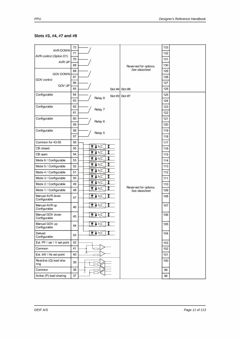
Slots #3, #4, #7 and #8
Relay 5
Relay 6
Relay 8
Relay 7
72
71
AVR UP 70
69
GOV DOWN 68
67
GOV UP 66
65
Configurable 64
63
Configurable 62
61
Configurable 60
59
Configurable 58
57
Common for 43-55 56
CB closed 55
CB open 54
Mode 6 / Configurable 53
Mode 5 / Configurable 52
Mode 4 / Configurable 51
Mode 3 / Configurable 50
Mode 2 / Configurable 49
Mode 1 / Configurable 48
Manual AVR down Configurable 47
Manual AVR up Configurable 46
Manual GOV down Configurable 45
Manual GOV up Configurable 44
Deload Configurable 43
Ext. PF / var / V set point 42
Common 41
Ext. kW / Hz set point 40
Reactive (Q) load sha-ring 39
Common 38
Active (P) load sharing 37
AVR DOWN 133
132
131
130
129
128
127
126
125
124
123
122
121
120
119
118
117
116
115
114
113
112
111
110
109
108
107
106
105
104
103
102
101
100
99
98
AVR control (Option D1)
GOV control
Reserved for options. See datasheet
Reserved for options. See datasheet
Slot #4 Slot #8
Slot #3 Slot #7

PPU Designer’s Reference Handbook
DEIF A/S Page 12 of 113
Applications The unit can be used for the applications listed in the table below. This depends on the selection of the running modes.
Select running mode Mode selection Application
Fixed frequency
Fixed power
Droop Load sharing
Island mode, stand-alone X X Island mode, load sharing with other gen-sets
X X
Fixed power to mains X X
Fixed frequency Select fixed frequency mode by deactivating mode 1 and mode 2. This running mode is typically used when the generator is running in island operation/stand alone. During island operation/stand alone the load connected to the generator cannot be changed through regulation of the gen-set. If the fuel supply to the engine is increased or decreased then the loading of the gen-set does not change – only the frequency will increase or decrease as a result of changed fuel supply.
Dependency Fixed frequency mode is active when:
Active mode Input
Fixed frequency
(Sync)
Fixed frequency
Fixed frequency
Start sync./control
25 ON ON ON Control inputs
Deload 43 OFF ON OFF CB open 54 ON ON OFF Breaker
feedbacks CB closed 55 OFF OFF ON Mode 1 48 OFF Mode inputs Mode 2 49
Mode inputs are not used when the CB is opened OFF
Regulator The frequency regulator is active in this mode. During fixed frequency operation the setpoint is typically the nominal frequency. (See page 62 for exact description of the setpoint).
Fixed power Select fixed power mode by activating mode 1 and deactivating mode 2. This running mode is typically used when the generator is running parallel to the mains. During
All combinations of the above applications are possible. The selection is made with the mode inputs called mode 1 (terminal 48) and mode 2 (terminal 49).
This mode is always used when the CB is opened regardless of the activation of the mode inputs. When the CB is opened nothing else but the frequency can change as a cause of changed governor regulation and therefore the mode inputs are not used. (Mode 3 (external setpoint) can still be used!)

PPU Designer’s Reference Handbook
DEIF A/S Page 13 of 113
fixed power operation, the gen-set cannot change the frequency because it is maintained by the grid. If the fuel supply to the engine is increased or decreased then the frequency of the gen-set does not change – only the load will increase or decrease as a result of changed fuel supply.
Dependency Fixed power mode is active when:
Active mode Input
Fixed power Fixed power (ramp down)
Start sync./control
25 ON ON Control inputs
Deload 43 OFF ON CB open 54 OFF OFF Breaker
feedbacks CB closed 55 ON ON Mode 1 48 ON ON Mode inputs Mode 2 49 OFF OFF
Regulator The power regulator is active in this mode. During fixed power operation, the setpoint is typically the setpoint adjusted in the display (menu 4041). (See page 62 for exact description of the setpoint).
Droop Select droop mode by deactivating mode 1 and activating mode 2. This running mode can be used on various occasions where it is required that the generator frequency drops with increasing load.
Base loaded operation When the generator is in parallel operation with the mains it will operate with different loading depending on the frequency. A high droop setting will cause the load to be relatively constant with changed frequency and a lower droop setting will give higher variations in load. This is shown in the diagrams below:
The droop mode adjusted in the PPU should not be confused with the governor droop: The governor droop has the purpose of applying stability in the regulation of the engine and does not give an actual droop if a controller (PPU) is installed. The PPU droop has the purpose of causing an actual speed droop. With this droop activated, the frequency will actually change with changing load.
PPU Designer’s Reference Handbook
DEIF A/S Page 14 of 113
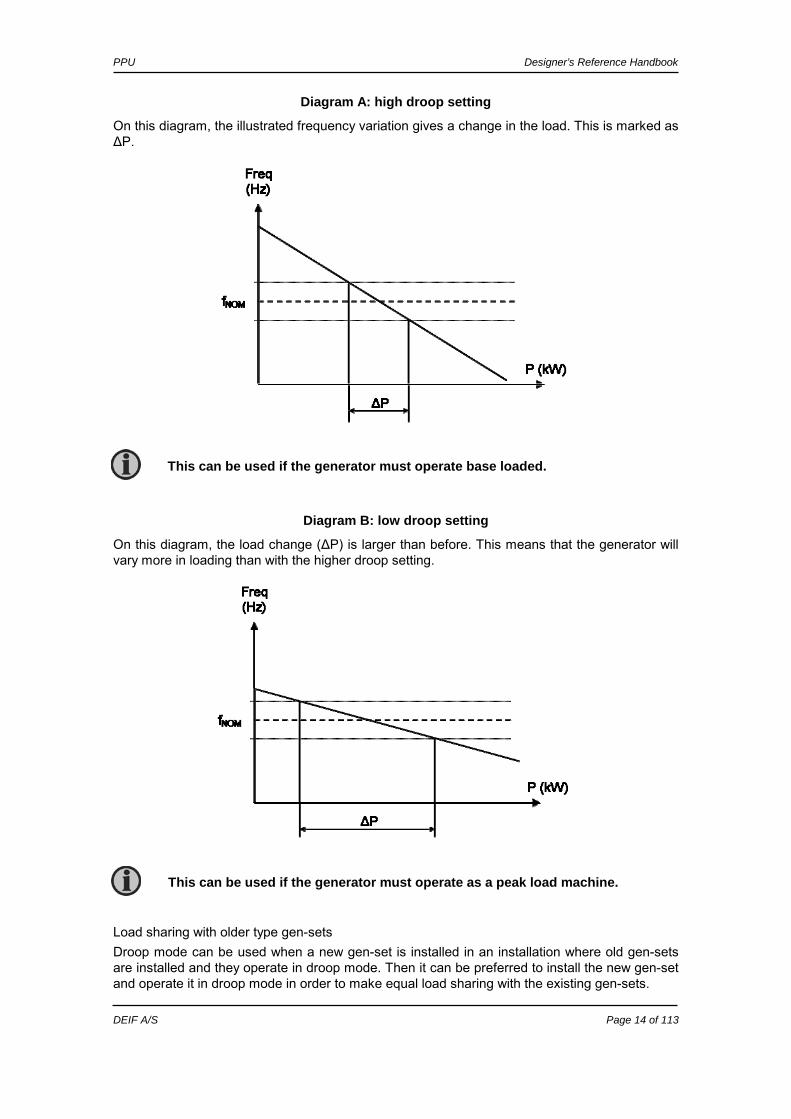
Diagram A: high droop setting
On this diagram, the illustrated frequency variation gives a change in the load. This is marked as ΔP.
Diagram B: low droop setting
On this diagram, the load change (ΔP) is larger than before. This means that the generator will vary more in loading than with the higher droop setting.
Load sharing with older type gen-sets Droop mode can be used when a new gen-set is installed in an installation where old gen-sets are installed and they operate in droop mode. Then it can be preferred to install the new gen-set and operate it in droop mode in order to make equal load sharing with the existing gen-sets.
This can be used if the generator must operate base loaded.
This can be used if the generator must operate as a peak load machine.
PPU Designer’s Reference Handbook
DEIF A/S Page 15 of 113
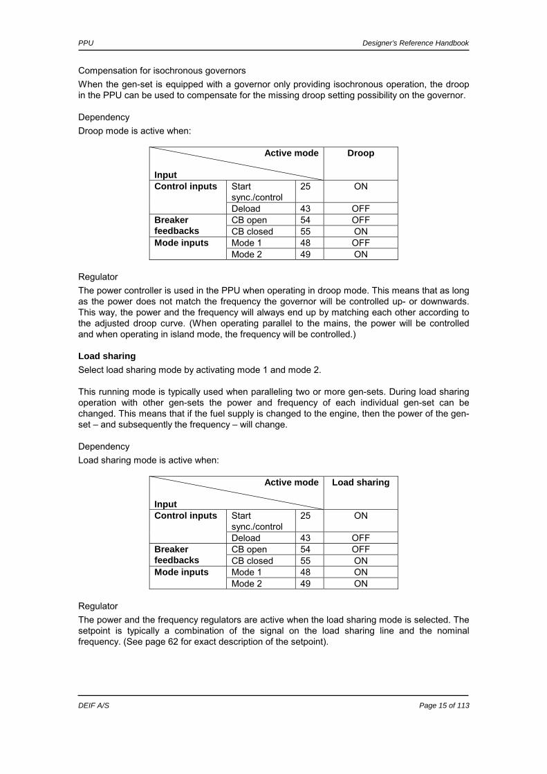
Compensation for isochronous governors When the gen-set is equipped with a governor only providing isochronous operation, the droop in the PPU can be used to compensate for the missing droop setting possibility on the governor.
Dependency Droop mode is active when:
Active mode Input
Droop
Start sync./control
25 ON Control inputs
Deload 43 OFF CB open 54 OFF Breaker
feedbacks CB closed 55 ON Mode 1 48 OFF Mode inputs Mode 2 49 ON
Regulator The power controller is used in the PPU when operating in droop mode. This means that as long as the power does not match the frequency the governor will be controlled up- or downwards. This way, the power and the frequency will always end up by matching each other according to the adjusted droop curve. (When operating parallel to the mains, the power will be controlled and when operating in island mode, the frequency will be controlled.)
Load sharing Select load sharing mode by activating mode 1 and mode 2. This running mode is typically used when paralleling two or more gen-sets. During load sharing operation with other gen-sets the power and frequency of each individual gen-set can be changed. This means that if the fuel supply is changed to the engine, then the power of the gen-set – and subsequently the frequency – will change.
Dependency Load sharing mode is active when:
Active mode Input
Load sharing
Start sync./control
25 ON Control inputs
Deload 43 OFF CB open 54 OFF Breaker
feedbacks CB closed 55 ON Mode 1 48 ON Mode inputs Mode 2 49 ON
Regulator The power and the frequency regulators are active when the load sharing mode is selected. The setpoint is typically a combination of the signal on the load sharing line and the nominal frequency. (See page 62 for exact description of the setpoint).

PPU Designer’s Reference Handbook
DEIF A/S Page 16 of 113
Measurement systems The PPU is designed for measurement of voltages between 100 and 690V AC. The AC wiring diagrams are shown in the installation instructions for further reference. In menu 6100, the measurement principle can be changed between three-phase, single phase and split phase. The menu for adjusting the measurement principle looks like this:
G 0 0 0VMode 0 Normal=0, Splitp.=1 SinglePhase=2 Mode
Press ‘SEL’ to change the mode and select ‘0’ for three-phase mode, ‘1’ for split phase mode and ‘2’ for single phase mode.
Three-phase When the PPU is delivered from the factory, the three-phase system is selected. When this principle is used, all three phases must be connected to the PPU. The following adjustments must be made in order to make the system ready for the three-phase measuring (example 400/230V AC): Adjustment Setting
Description Adjust to value
4014 Nom.voltage Phase-phase voltage 400V AC
4021 Transformer Gen Primary voltage of the voltage transformer (if installed) UNOM
4022 Transformer Gen Secondary voltage of the voltage transformer (if installed) UNOM
4031 Transformer BUS Primary voltage of the voltage transformer (if installed) UNOM
4032 Transformer BUS Secondary voltage of the voltage transformer (if installed) UNOM
The settings can only be changed using the display. Press the JUMP push-button and go to the menu 6100.
Configure the PPU to match the correct measuring system. When in doubt, contact the switchboard manufacturer for information about the required adjustment.
PPU Designer’s Reference Handbook
DEIF A/S Page 17 of 113
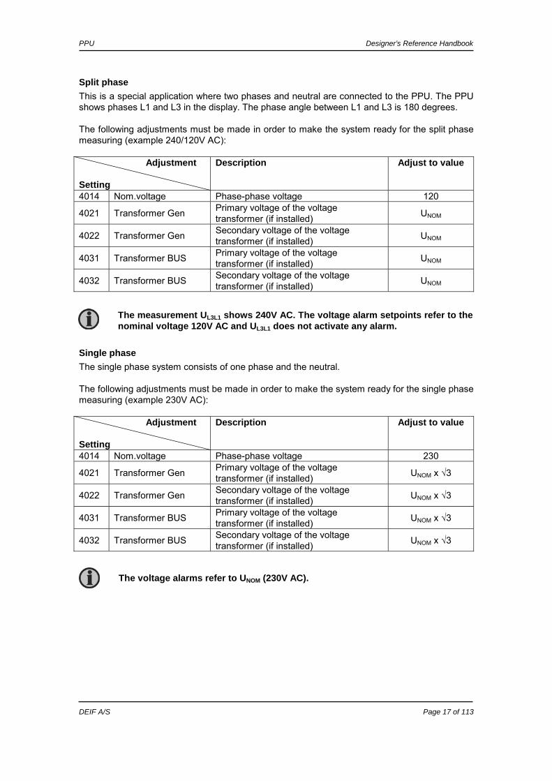
Split phase This is a special application where two phases and neutral are connected to the PPU. The PPU shows phases L1 and L3 in the display. The phase angle between L1 and L3 is 180 degrees. The following adjustments must be made in order to make the system ready for the split phase measuring (example 240/120V AC): Adjustment Setting
Description Adjust to value
4014 Nom.voltage Phase-phase voltage 120
4021 Transformer Gen Primary voltage of the voltage transformer (if installed) UNOM
4022 Transformer Gen Secondary voltage of the voltage transformer (if installed) UNOM
4031 Transformer BUS Primary voltage of the voltage transformer (if installed) UNOM
4032 Transformer BUS Secondary voltage of the voltage transformer (if installed) UNOM
Single phase The single phase system consists of one phase and the neutral. The following adjustments must be made in order to make the system ready for the single phase measuring (example 230V AC): Adjustment Setting
Description Adjust to value
4014 Nom.voltage Phase-phase voltage 230
4021 Transformer Gen Primary voltage of the voltage transformer (if installed) UNOM x √3
4022 Transformer Gen Secondary voltage of the voltage transformer (if installed) UNOM x √3
4031 Transformer BUS Primary voltage of the voltage transformer (if installed) UNOM x √3
4032 Transformer BUS Secondary voltage of the voltage transformer (if installed) UNOM x √3
The measurement UL3L1 shows 240V AC. The voltage alarm setpoints refer to the nominal voltage 120V AC and UL3L1 does not activate any alarm.
The voltage alarms refer to UNOM (230V AC).

PPU Designer’s Reference Handbook
DEIF A/S Page 18 of 113
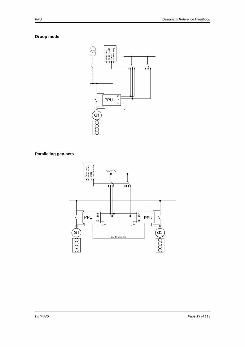
Single diagrams The PPU can be used for a numerous applications. Below is shown a few examples, but due to the flexibility of the product it is not possible to show all possibilities. The flexibility is one of the great advantages of the PPU controller.
Stand-alone
Gen-set parallel to mains
PPU Designer’s Reference Handbook
DEIF A/S Page 19 of 113
Droop mode
Paralleling gen-sets

PPU Designer’s Reference Handbook
DEIF A/S Page 20 of 113
Gen-sets parallel to shaft generator and PLC controlled
Gen-set parallel to mains and AVR control
PPU Designer’s Reference Handbook
DEIF A/S Page 21 of 113
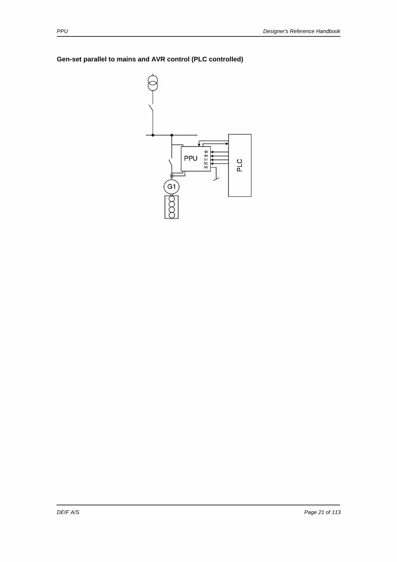
Gen-set parallel to mains and AVR control (PLC controlled)

PPU Designer’s Reference Handbook
DEIF A/S Page 22 of 113
Sequences The following chapter contains information about the sequences of the PPU. These sequences will be described:
Sequence Description CB ON Synchronising CB ON Black out closing CB OFF Open breaker CB OFF Deload/open breaker
CB ON sequence/synchronising The CB ON sequence can be started when the generator is running and the terminal 25 (start sync./control) is activated. The regulation will start and control the gen-set in order to synchronise the breaker.
Interruption of the CB ON (synchronising) sequence
Input 25 deactivated Input 43 activated 25 = ON at the same time CB close UBB measured below 70% 70% x UNOM Synchronising failure General failure Alarm + sync block state
The busbar voltage must be above 70% x UNOM in order to initiate the synchronising.
When the CB opens there is a 10 s delay that prevents it from closing immediately after it has opened. This is to ensure that there is sufficient time to change mode and control inputs.

PPU Designer’s Reference Handbook
DEIF A/S Page 23 of 113
CB ON sequence/black out closing In order to make a black out closing, terminal 25 must be activated and the measurements from the busbar must be missing. The breaker will close if the voltage is below 30% x UNOM.
Interruption of the CB ON (black close) sequence
Input 25 deactivated Input 43 activated 25 = ON at the same time U gen not OK Limit set in menu 2042 f gen not OK Limit set in menu 2041 Black closing not enabled Enabled in menu 2040 CB close UBB measured above 30% General failure Alarm + sync block state
CB OFF/open breaker The CB can be opened instantly by the PPU. The sequence is started by this selection of the control inputs:
Terminal Description Input state 25 Start sync./control ON 43 Deload ON 48 Mode 1 OFF 49 Mode 2 OFF
The CB open signal will be issued immediately when the combination of the control inputs are as mentioned in the table above.
CB OFF/deload The CB can be opened by the PPU after a smooth deload period where the load has decreased to the breaker open point (menu 2152). The sequence is started by one of the following three combinations of inputs:
Terminal Description Input state 25 Start sync./control ON ON ON 43 Deload ON ON ON 48 Mode 1 ON ON OFF 49 Mode 2 ON OFF ON
The CB open signal will be issued when the load has been below the breaker open point for 1 second. In order to interrupt the deload sequence the input 43 must be deactivated. Then the PPU will continue the operation according to the present mode selection. (The deload sequence can also be interrupted if the input ‘Start sync./control’ is deactivated. But then the entire regulation is deactivated).
The busbar voltage must be below 30% x UNOM in order to initiate the black busbar closing.
When the CB opens there is a 10 s delay that prevents it from closing immediately after it has opened. This is to ensure that there is sufficient time to change mode and control inputs.

PPU Designer’s Reference Handbook
DEIF A/S Page 24 of 113
5. Display unit and menu structure This chapter deals with the display unit including the push-button and LED functions. In addition, the unit menu structure will be presented.
Display unit The display has 4 different lines, each with 20 characters, and holds a number of push-button functions.
Push-button functions The display unit holds a number of push-button functions which are presented below.
INFO: Shifts the display 3 lower lines to show the alarm list. JUMP: Enters a specific menu number selection. All settings have a specific number
attached to them. The JUMP button enables the user to select and display any setting without having to navigate through the menus (see later).
VIEW: Shifts the first line displaying in the setup menus. LOG: Shifts the display 3 lower lines to show the event and alarm list. The list holds
150 events. The events are not deleted when the auxiliary supply is switched off.
: Moves the cursor left for manoeuvring in the menus.
: Increases the value of the selected setpoint (in the setup menu). In the daily use display, this button function is used for scrolling the second line displaying of generator values in the setup menu or for scrolling through the view windows (V1).
SEL: Is used to select the underscored entry in the fourth line of the display.
: Decreases the value of the selected setpoint (in the setup menu). In the daily use display, this button function is used for scrolling the second line displaying of generator values in the setup menu or for scrolling through the view windows (V1).
: Moves the cursor right for manoeuvring in the menus. BACK: Jumps one step backwards in the menu (to previous display or to the entry
window).
Display dimensions are H x W = 115 x 220 mm (4.528” x 9.055”).
PPU Designer’s Reference Handbook
DEIF A/S Page 25 of 113
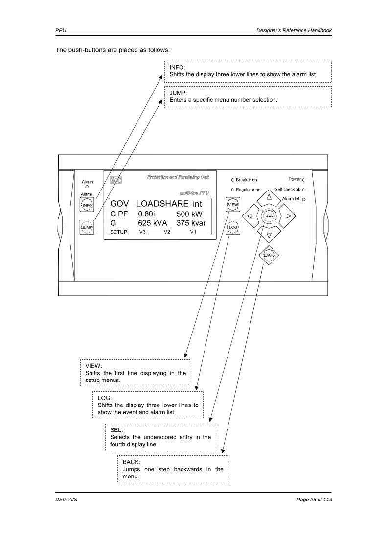
The push-buttons are placed as follows:
INFO: Shifts the display three lower lines to show the alarm list.
JUMP: Enters a specific menu number selection.
VIEW: Shifts the first line displaying in the setup menus.
LOG: Shifts the display three lower lines to show the event and alarm list.
SEL: Selects the underscored entry in the fourth display line.
BACK: Jumps one step backwards in the menu.
V1375 kvar500 kW0.80i
625 kVASETUPGG PFGOV LOADSHARE int
V2V3

PPU Designer’s Reference Handbook
DEIF A/S Page 26 of 113
LED functions The display unit holds 10 LED functions. The colour is green or red or a combination in different situations. Alarm: LED flashing indicates that unacknowledged alarms are present. LED fixed light indicates that ALL alarms are acknowledged. Power: LED indicates that the auxiliary supply is switched on. Self check OK: LED indicates that the self check is OK. Alarm inh: LED flashing indicates that the loss of mains protections is inhibited. (Block loss
of mains input is ON). LED fixed light indicates that the inhibit function is ON. Breaker on: LED green light indicates that the generator breaker is closed.

PPU Designer’s Reference Handbook
DEIF A/S Page 27 of 113
The display LEDs are indicating as follows:
Alarm inh.: Fixed: Indicates alarm inhibit active. Flashing: Block loss of mains protection.
Power: Indicates auxiliary supply ON.
Alarm: Flashing: Unacknowledged alarms present. Fixed: Acknowledged alarms present.
Self check OK: Indicates self check OK.
CB is in closed position.
The GOV/(AVR) regulation is switched ON.
V1375 kvar500 kW0.80i
625 kVASETUPGG PFGOV LOADSHARE int
V2V3

PPU Designer’s Reference Handbook
DEIF A/S Page 28 of 113
Menu structure The display includes two menu systems which can be used without password entry:
View menu system This is the commonly used menu system. 15 windows are configurable and can be entered by using the arrow push-buttons. Setup menu system This menu system is used for setting up the unit, and if the user needs detailed information that is not available in the view menu system. Changing of parameter settings is password protected.
Entry window When the unit is powered up, an entry window appears. The entry window is the turning point in the menu structure and as such the gateway to the other menus. It can always be reached by pressing the BACK push-button 3 times.
The alarm list will appear at power up if an alarm is present.

PPU Designer’s Reference Handbook
DEIF A/S Page 29 of 113
View menu The view menus (V1, V2 and V3) are the most commonly used menus of the unit.
First display line Second and third display line Operational status or measurements Measurements relating to operational status
Fourth display line Selection of setup and view menus
In the view menus various measured values are shown on the display.
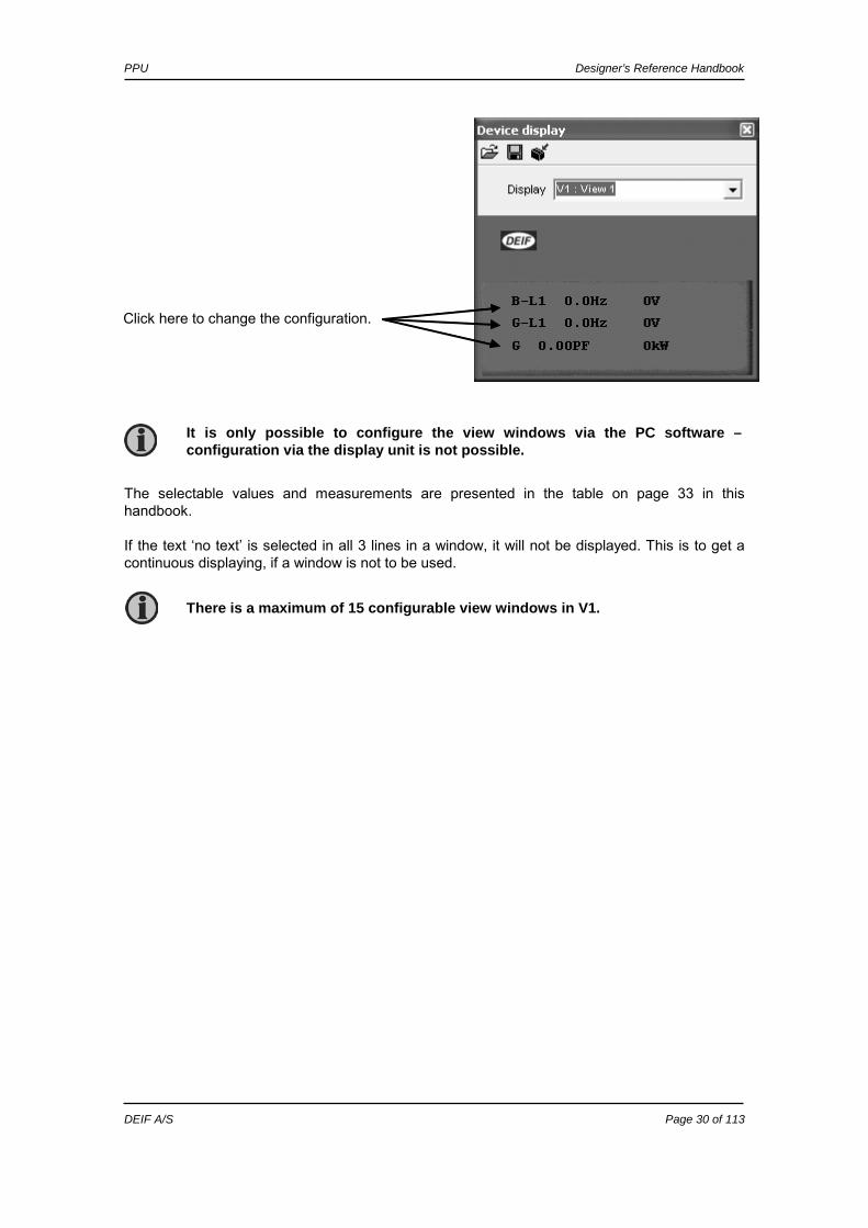
View window configuration The individual view windows need to be configured through the PC software in the dialog box illustrated below.
Use this button to go to the configuration.
Select the view window to be configured.
PPU Designer’s Reference Handbook
DEIF A/S Page 30 of 113
The selectable values and measurements are presented in the table on page 33 in this handbook. If the text ‘no text’ is selected in all 3 lines in a window, it will not be displayed. This is to get a continuous displaying, if a window is not to be used.
Click here to change the configuration.
It is only possible to configure the view windows via the PC software – configuration via the display unit is not possible.
There is a maximum of 15 configurable view windows in V1.

PPU Designer’s Reference Handbook
DEIF A/S Page 31 of 113
View window overview
* The default window is automatically selected after the generator breaker closure when the
gen-set is in normal operation, e.g. fixed power mode after the ramping up.
Windows V1 View 1 View 2 View 3 View 4 View 5 View 6 View 7 View 8 View 9 View 10 View 11 View 12 View 13 View 14 View 15
Manual selection with key UP or key DOWN push-buttons
Windows V 2 V 3 View 1 View 2 View 3 View 4 View 5
Changes automatically be-tween the 5 first views: 1. View 1 (Start prepare) 2. View 2 (Sync.) 3. View 3 (Ramp up/down) 4. View 4 5. View 5 (Default*) No manual selection. All three lines show measuring values.
Changes automatically be-tween the 5 first views: 1. View 1 (Start prepare) 2. View 2 (Sync.) 3. View 3 (Ramp up/down) 4. View 4 5. View 5 (Default*) No manual selection. Line 1 shows the text 1…5 (above). Line 2 and line 3 show measurements.
PPU Designer’s Reference Handbook
DEIF A/S Page 32 of 113
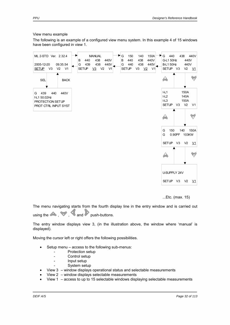
View menu example The following is an example of a configured view menu system. In this example 4 of 15 windows have been configured in view 1.
...Etc. (max. 15)
The menu navigating starts from the fourth display line in the entry window and is carried out
using the , , and push-buttons. The entry window displays view 3, (in the illustration above, the window where ‘manual’ is displayed). Moving the cursor left or right offers the following possibilities.
• Setup menu – access to the following sub-menus: - Protection setup - Control setup - Input setup - System setup
• View 3 – window displays operational status and selectable measurements • View 2 – window displays selectable measurements • View 1 – access to up to 15 selectable windows displaying selectable measurements
ML 2-STD Ver. 2.32.4
2005-12-20 09.35.54SETUP V3 V2 V1
G 440 438 440VG-L1 50Hz 440VB-L1 50Hz 440VSETUP V3 V2 V1
MANUALB 440 438 440VG 439 438 440VSETUP V3 V2 V1
G 150 140 150AB 440 438 440VG 440 438 440VSETUP V3 V2 V1
I-L1 150AI-L2 140AI-L3 150ASETUP V3 V2 V1
G 150 140 150AG 0.90PF 103KW
SETUP V3 V2 V1
U-SUPPLY 24V
SETUP V3 V2 V1
G 439 440 440Vf-L1 50.02HzPROTECTION SETUPPROT CTRL INPUT SYST
BACKSEL
PPU Designer’s Reference Handbook
DEIF A/S Page 33 of 113
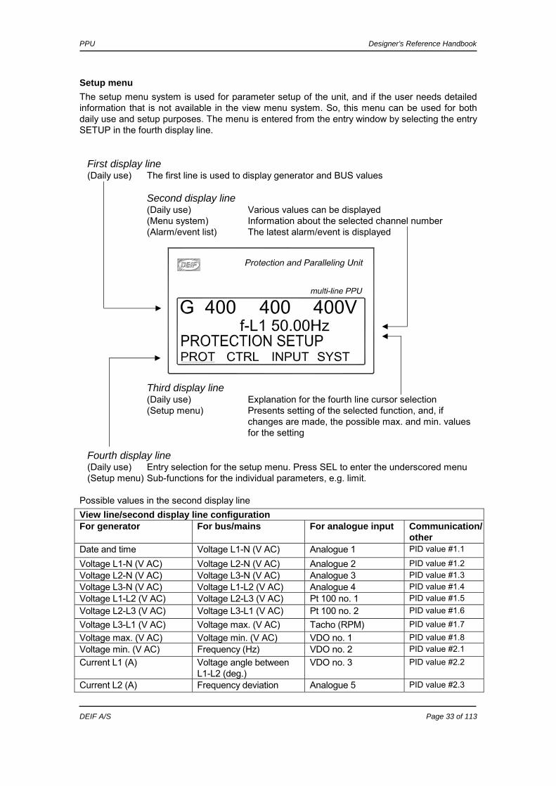
Setup menu The setup menu system is used for parameter setup of the unit, and if the user needs detailed information that is not available in the view menu system. So, this menu can be used for both daily use and setup purposes. The menu is entered from the entry window by selecting the entry SETUP in the fourth display line. First display line (Daily use) The first line is used to display generator and BUS values Second display line (Daily use) Various values can be displayed (Menu system) Information about the selected channel number (Alarm/event list) The latest alarm/event is displayed Third display line (Daily use) Explanation for the fourth line cursor selection (Setup menu) Presents setting of the selected function, and, if
changes are made, the possible max. and min. values for the setting
Fourth display line (Daily use) Entry selection for the setup menu. Press SEL to enter the underscored menu (Setup menu) Sub-functions for the individual parameters, e.g. limit.
Possible values in the second display line View line/second display line configuration For generator For bus/mains For analogue input Communication/
other Date and time Voltage L1-N (V AC) Analogue 1 PID value #1.1
Voltage L1-N (V AC) Voltage L2-N (V AC) Analogue 2 PID value #1.2 Voltage L2-N (V AC) Voltage L3-N (V AC) Analogue 3 PID value #1.3 Voltage L3-N (V AC) Voltage L1-L2 (V AC) Analogue 4 PID value #1.4 Voltage L1-L2 (V AC) Voltage L2-L3 (V AC) Pt 100 no. 1 PID value #1.5 Voltage L2-L3 (V AC) Voltage L3-L1 (V AC) Pt 100 no. 2 PID value #1.6
Voltage L3-L1 (V AC) Voltage max. (V AC) Tacho (RPM) PID value #1.7 Voltage max. (V AC) Voltage min. (V AC) VDO no. 1 PID value #1.8 Voltage min. (V AC) Frequency (Hz) VDO no. 2 PID value #2.1 Current L1 (A) Voltage angle between
L1-L2 (deg.) VDO no. 3 PID value #2.2
Current L2 (A) Frequency deviation Analogue 5 PID value #2.3

PPU Designer’s Reference Handbook
DEIF A/S Page 34 of 113
View line/second display line configuration For generator For bus/mains For analogue input Communication/
other (df/dt) (Hz/sec.)
Current L3 (A) Voltage angle between generator voltage and bus voltage (deg.)
Analogue 6 PID value #2.4
Frequency L1 (Hz) Power supply voltage (V DC)
Analogue 7 PID value #2.5
Frequency L2 (Hz) Analogue 8 PID value #2.6 Frequency L3 (Hz) PID value #2.7 Active power (kW) PID value #2.8 Reactive power (kVAr) EIC speed Apparent power (kVA) EIC Coolant
Temp. Energy counter (kWh) EIC Oil Pressure Power factor EIC Faults Voltage angle between L1-L2 (deg.)
EIC Oil Temp.
Voltage angle between L2-L3 (deg.)
EIC Fuel Temp.
Voltage angle between L3-L1 (deg.)
EIC Boost Pressure
Run time (h) EIC Air Inlet Temp.
Number of CB operations EIC Coolant Level EIC Fuel Rate EIC Charge Air
Pres. EIC Charge Air
Temp. EIC D.D. %
Torque EIC Actual %
torque EIC Acc. pedal
pos. EIC % Load, C.
Speed EIC Air Inlet Pres. EIC Exhaust gas
Temp EIC Engine Hours EIC Oil F. Diff
Pres EIC Battery
voltage EIC Fuel Del.
Pres. EIC Oil level EIC Crankcase
Pres. EIC Coolant
Pressure EIC Water In Fuel

PPU Designer’s Reference Handbook
DEIF A/S Page 35 of 113
View line/second display line configuration For generator For bus/mains For analogue input Communication/
other EIC Blowby Flow EIC Fuel Rail
Pres.
EIC Timing Rail Pres
EIC Aftercooler W.T.
Setup example The following example illustrates how a specific setting is changed in the setup menu. In this case Reverse power is the selected parameter.
G 439 440 440V1010 Reverse PowerSetpoint -5.0 %LIM DEL OA OB ENA C
first entry
G 439 440 440V1020 Over current 1Setpoint 115.0 %LIM DEL OA OB ENA C
G 439 440 440VEnter passw. 1999
ENTER
G 439 440 440V1011 Reverse power-50.0 -5.0 0.0%RESET SAVE
Yes
No
BACK SEL
INCREASE NO
DECREASE NO
Increase setting
Decrease setting
moves the cursor
G 439 440 440V f-L1 50.01 HzPROTECTION SETUPPROT CTRL INPUT SYST
SELBACK
PID values are CAT® CCM communication values, EIC values are CAN J1939 communication values.

PPU Designer’s Reference Handbook
DEIF A/S Page 36 of 113
Password The unit includes one configurable user password level. However, the device can be accessed by means of two additional password levels, should the configurable user password be lost. Available password levels: Password level Factory setting Menu for
configurationAccess Log entry
User configurable 2000 4971 All L2 password Back up password 4972 4972 All L1 password DEIF password #### None All L0 password
Parameter access To get access to adjust the parameters from the utility software, the user configurable password (L2 password) must be entered. If the user configurable password (L2 password) is not entered, it is not possible to enter the parameters from the utility software.
The factory passwords must be changed if the operator of the gen-set is not allowed to change the parameters.
Contact DEIF A/S, Customer service (tel. +45 96149614) for details regarding the DEIF back-up password, should the user configurable backup password be lost.
To start using the new password from the utility software it will be necessary to close the programme and open it again.

PPU Designer’s Reference Handbook
DEIF A/S Page 37 of 113
6. Additional functions This chapter describes the additional functions.
Language selection The language of the PPU is adjusted to English from the factory. The following languages can be selected (menu 4230):
Language English name English English Deutsch German Français French Español Spanish
Start
Press JUMP push button
Goto menu 4230 -
press SEL to enter menu
HINT:use keyUP or
keyDOWN
press SEL to change
selection
password entered enter password
No
select language and
press SEL
Yes
HINT:use keyUP or
keyDOWN
End
Use the flowchart below to navigate through the display if the language must be changed.

PPU Designer’s Reference Handbook
DEIF A/S Page 38 of 113
Alarm function The alarm function of the PPU includes possibility to display the alarm texts, activate relays or displaying alarm texts combined with relay outputs.
Setup The alarms must typically be setup with setpoint, timer, relay outputs and enabling. The adjustable setpoints of the individual alarms vary in range, e.g. the minimum and maximum settings.
Alarm display All enabled alarms will be shown in the display unless the Output A as well as the output B are adjusted to a ‘limit’ relay.
Definitions There are three states for an enabled alarm. 1. Alarm is not present: The display does not show any alarm. The alarm LED is dark. 2. Un-acknowledged state: The alarm has exceeded its setpoint and delay, and the alarm
message is displayed. The PPU is in the alarm state and it can only leave the alarm state if the cause of the alarm disappears and the alarm message is acknowledged at the same time. The alarm LED is flashing.
3. Acknowledged state: The alarm will be in an acknowledged state if the alarm situation
is present and the alarm has been acknowledged. The alarm LED is lit with fixed light. Any new alarm will make the LED flash.
Alarm acknowledge The alarms can be acknowledged in two ways. Either by means of the binary input ‘Alarm acknowledge’ or the push-buttons on the display.
Binary acknowledge input The alarm acknowledge input acknowledges all present alarms and the Alarm LED will change from flashing light to fixed light (alarms still present) or no light (no alarms present).
Display acknowledge (push-buttons) The display can be used for alarm acknowledgement when the alarm info window is entered. Pressing the ‘INFO’ button will open this window. The alarm information window displays one alarm at a time together with the alarm state (alarm acknowledged or not). If the alarm is unacknowledged, move the cursor to ‘ACK’ and press select to acknowledge it.
If output A and output B are adjusted to a limit relay then the alarm message will not appear but the limit relay will activate at a given condition.
It is not possible to acknowledge individual alarms with the binary alarm acknowledge input. All alarms will be acknowledged when the input is activated.
PPU Designer’s Reference Handbook
DEIF A/S Page 39 of 113
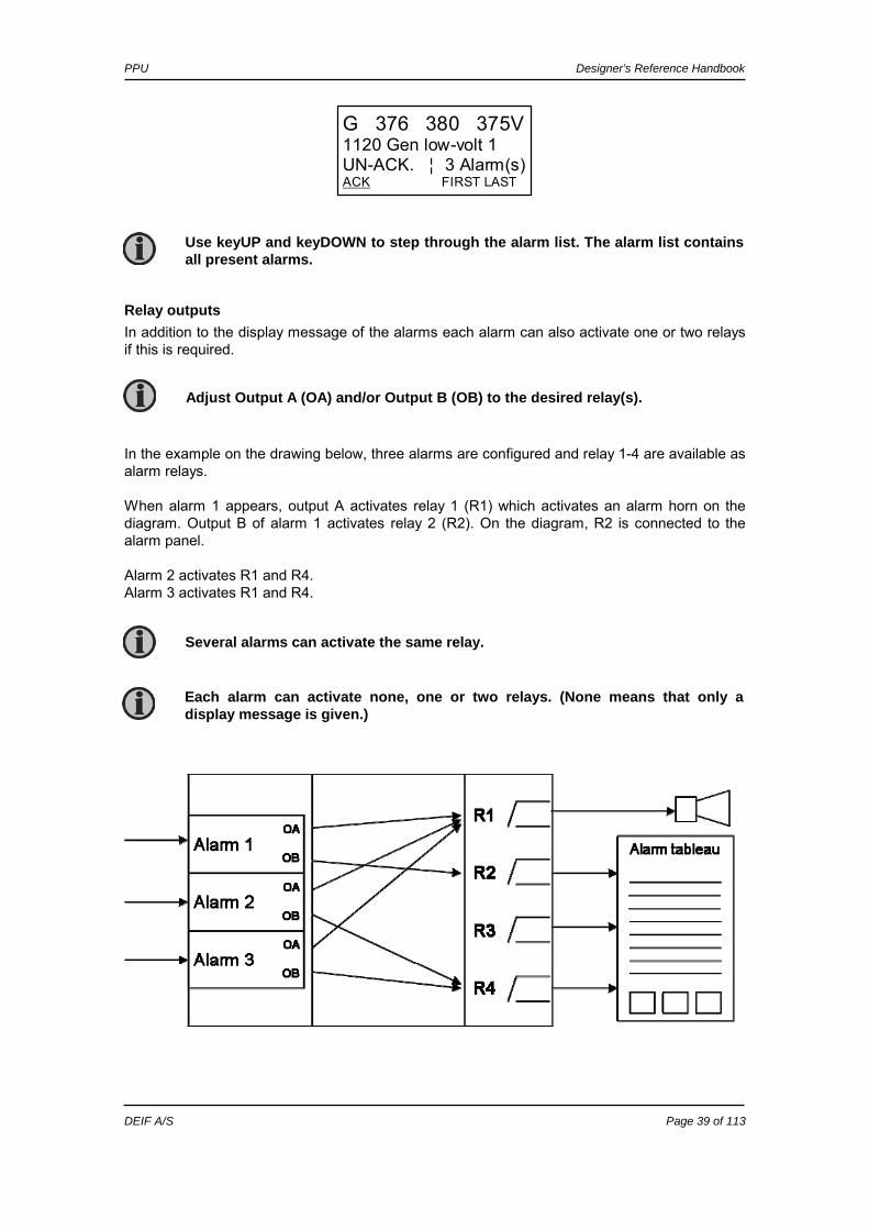
Relay outputs In addition to the display message of the alarms each alarm can also activate one or two relays if this is required. In the example on the drawing below, three alarms are configured and relay 1-4 are available as alarm relays. When alarm 1 appears, output A activates relay 1 (R1) which activates an alarm horn on the diagram. Output B of alarm 1 activates relay 2 (R2). On the diagram, R2 is connected to the alarm panel. Alarm 2 activates R1 and R4. Alarm 3 activates R1 and R4.
Use keyUP and keyDOWN to step through the alarm list. The alarm list contains all present alarms.
Adjust Output A (OA) and/or Output B (OB) to the desired relay(s).
Each alarm can activate none, one or two relays. (None means that only a display message is given.)
Several alarms can activate the same relay.
G 376 380 375V1120 Gen low-volt 1 UN-ACK. ¦ 3 Alarm(s)ACK FIRST LAST
PPU Designer’s Reference Handbook
DEIF A/S Page 40 of 113
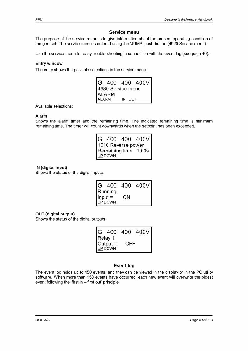
Service menu The purpose of the service menu is to give information about the present operating condition of the gen-set. The service menu is entered using the ‘JUMP’ push-button (4920 Service menu). Use the service menu for easy trouble-shooting in connection with the event log (see page 40).
Entry window The entry shows the possible selections in the service menu.
G 400 400 400V4980 Service menu ALARM ALARM IN OUT
Available selections: Alarm Shows the alarm timer and the remaining time. The indicated remaining time is minimum remaining time. The timer will count downwards when the setpoint has been exceeded.
G 400 400 400V1010 Reverse power Remaining time 10.0sUP DOWN
IN (digital input) Shows the status of the digital inputs.
G 400 400 400VRunning Input = ON UP DOWN
OUT (digital output) Shows the status of the digital outputs.
G 400 400 400VRelay 1 Output = OFF UP DOWN
Event log The event log holds up to 150 events, and they can be viewed in the display or in the PC utility software. When more than 150 events have occurred, each new event will overwrite the oldest event following the ‘first in – first out’ principle.
PPU Designer’s Reference Handbook
DEIF A/S Page 41 of 113
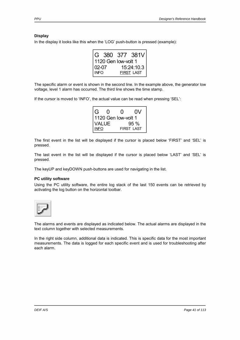
Display In the display it looks like this when the ‘LOG’ push-button is pressed (example):
The specific alarm or event is shown in the second line. In the example above, the generator low voltage, level 1 alarm has occurred. The third line shows the time stamp. If the cursor is moved to ‘INFO’, the actual value can be read when pressing ‘SEL’:
The first event in the list will be displayed if the cursor is placed below ‘FIRST’ and ‘SEL’ is pressed. The last event in the list will be displayed if the cursor is placed below ‘LAST’ and ‘SEL’ is pressed. The keyUP and keyDOWN push-buttons are used for navigating in the list.
PC utility software Using the PC utility software, the entire log stack of the last 150 events can be retrieved by activating the log button on the horizontal toolbar.
The alarms and events are displayed as indicated below. The actual alarms are displayed in the text column together with selected measurements. In the right side column, additional data is indicated. This is specific data for the most important measurements. The data is logged for each specific event and is used for troubleshooting after each alarm.
G 0 0 0V 1120 Gen low-volt 1 VALUE 95 % INFO FIRST LAST
G 380 377 381V1120 Gen low-volt 1 02-07 15:24:10.3INFO FIRST LAST

PPU Designer’s Reference Handbook
DEIF A/S Page 42 of 113
Counters Counters for various values are included in the PPU, and two of those can be adjusted if necessary, for instance if the PPU is installed on an existing gen-set (adjust the running hours) or a new circuit breaker has been installed (adjust number of CB operations). The table shows the adjustable values and their function: Description Function Comment 4121 Running time Offset adjustment of the total running
hours counter. Counting when the running feedback is present (voltage).
4122 CB operations Offset adjustment of the number of circuit breaker operations.
Counting at each CB close command.
4123 kWh reset Resets the kWh counter. Automatically resets to OFF after the reset. The reset function cannot be left active.
The menus 4121 and 4122 will automatically change their setting when the run time and CB operations count.
The entire log can be saved in Excel format and used in that particular programme.

PPU Designer’s Reference Handbook
DEIF A/S Page 43 of 113
kWh/kVArh counters The PPU has two transistor outputs each representing a value for the power production. The outputs are pulse outputs, and the pulse length for each of the activations is 1 second.
Term. number
Output
20 kWh 21 kVArh 22 Common terminal
The number of pulses depends on the actual adjusted setting of the nominal power: Generator power Value Number of pulses (kWh) Number of pulses (kVArh) PNOM <100 kW 1 pulse/kWh 1 pulse/kVArh PNOM 100-1000 kW 1 pulse/10 kWh 1 pulse/10 kVArh PNOM >1000 kW 1 pulse/100 kWh 1 pulse/100 kVArh
Self check The PPU has a self check function and a status relay output that responds to this function. The status relay is prepared for 24V DC/1A, and it is normally energised. The self check is monitoring the programme execution. Should this fail, i.e. in the unlikely event of microprocessor failure, then the self check function deactivates the status relay. Use the output from the status relay to perform a proper action for the gen-set application. Typically, this would mean a shut down of the gen-set since it is now operating without protection and control.
Text in status line If the display is installed it will show various messages depending on the running condition. To see these messages, the view menu system must be selected (press ‘BACK’ three times) and move the cursor to V3. Typically, the messages are self explaining so the operator knows what state the generator is in.
The kWh measurement is shown in the display as well, but the kVArh measurement is only available through the transistor output.
Be careful – the maximum burden for the transistor outputs is 10mA.
The protections in the PPU are not functioning when the self check function deactivates the status relay.
There are two ‘Self check ok’ LEDs on the PPU. One is placed on the display and one on the main unit. The LEDs are lit when the PPU is functioning well.
Use the status texts for daily operation as well as for trouble shooting.
PPU Designer’s Reference Handbook
DEIF A/S Page 44 of 113
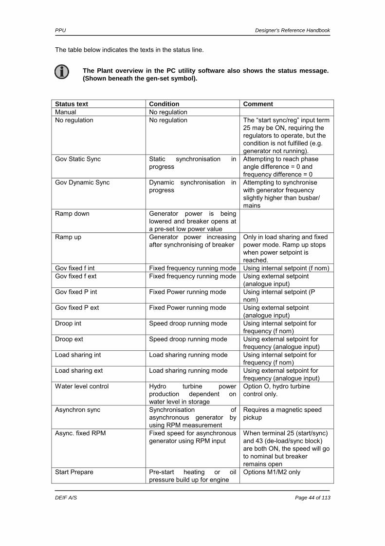
The table below indicates the texts in the status line. Status text Condition Comment Manual No regulation No regulation No regulation The “start sync/reg” input term
25 may be ON, requiring the regulators to operate, but the condition is not fulfilled (e.g. generator not running).
Gov Static Sync Static synchronisation in progress
Attempting to reach phase angle difference = 0 and frequency difference = 0
Gov Dynamic Sync Dynamic synchronisation in progress
Attempting to synchronise with generator frequency slightly higher than busbar/ mains
Ramp down Generator power is being lowered and breaker opens at a pre-set low power value
Ramp up Generator power increasing after synchronising of breaker
Only in load sharing and fixed power mode. Ramp up stops when power setpoint is reached.
Gov fixed f int Fixed frequency running mode Using internal setpoint (f nom) Gov fixed f ext Fixed frequency running mode Using external setpoint
(analogue input) Gov fixed P int Fixed Power running mode Using internal setpoint (P
nom) Gov fixed P ext Fixed Power running mode Using external setpoint
(analogue input) Droop int Speed droop running mode Using internal setpoint for
frequency (f nom) Droop ext Speed droop running mode Using external setpoint for
frequency (analogue input) Load sharing int Load sharing running mode Using internal setpoint for
frequency (f nom) Load sharing ext Load sharing running mode Using external setpoint for
frequency (analogue input) Water level control Hydro turbine power
production dependent on water level in storage
Option O, hydro turbine control only.
Asynchron sync Synchronisation of asynchronous generator by using RPM measurement
Requires a magnetic speed pickup
Async. fixed RPM Fixed speed for asynchronous generator using RPM input
When terminal 25 (start/sync) and 43 (de-load/sync block) are both ON, the speed will go to nominal but breaker remains open
Start Prepare Pre-start heating or oil pressure build up for engine
Options M1/M2 only
The Plant overview in the PC utility software also shows the status message. (Shown beneath the gen-set symbol).
PPU Designer’s Reference Handbook
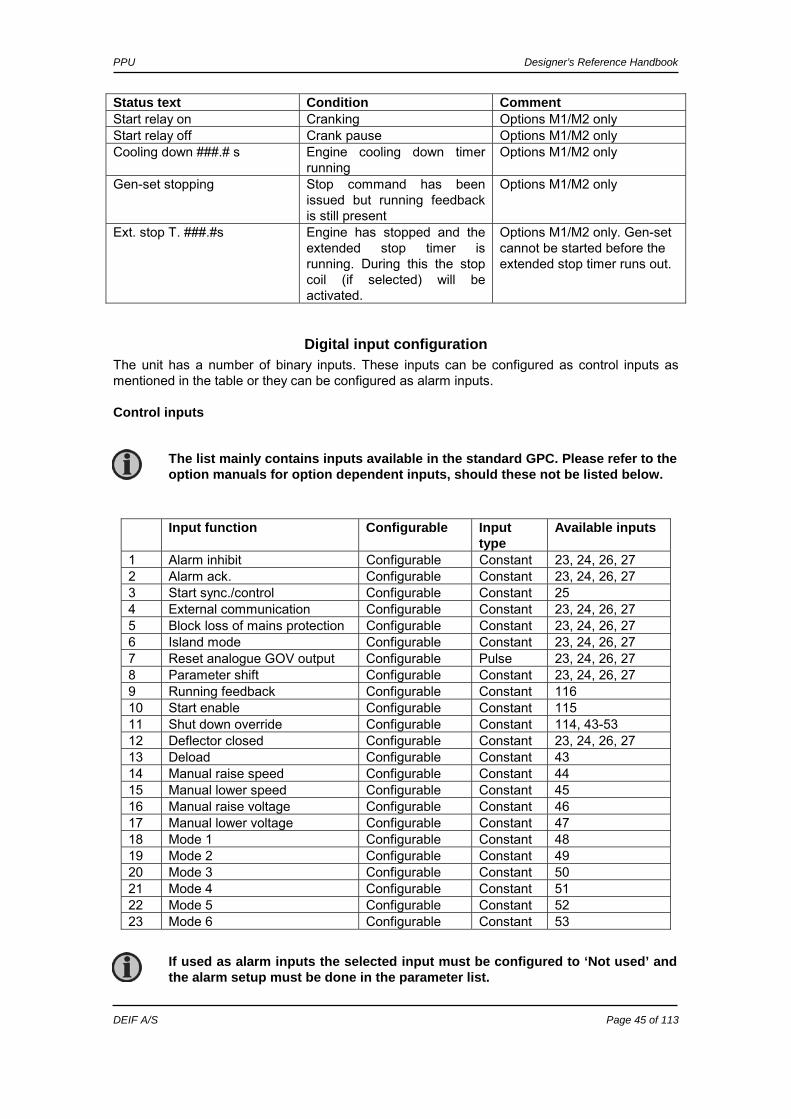
DEIF A/S Page 45 of 113
Status text Condition Comment Start relay on Cranking Options M1/M2 only Start relay off Crank pause Options M1/M2 only Cooling down ###.# s Engine cooling down timer
running Options M1/M2 only
Gen-set stopping Stop command has been issued but running feedback is still present
Options M1/M2 only
Ext. stop T. ###.#s Engine has stopped and the extended stop timer is running. During this the stop coil (if selected) will be activated.
Options M1/M2 only. Gen-set cannot be started before the extended stop timer runs out.
Digital input configuration The unit has a number of binary inputs. These inputs can be configured as control inputs as mentioned in the table or they can be configured as alarm inputs.
Control inputs
Input function Configurable Input type
Available inputs
1 Alarm inhibit Configurable Constant 23, 24, 26, 27 2 Alarm ack. Configurable Constant 23, 24, 26, 27 3 Start sync./control Configurable Constant 25 4 External communication Configurable Constant 23, 24, 26, 27 5 Block loss of mains protection Configurable Constant 23, 24, 26, 27 6 Island mode Configurable Constant 23, 24, 26, 27 7 Reset analogue GOV output Configurable Pulse 23, 24, 26, 27 8 Parameter shift Configurable Constant 23, 24, 26, 27 9 Running feedback Configurable Constant 116 10 Start enable Configurable Constant 115 11 Shut down override Configurable Constant 114, 43-53 12 Deflector closed Configurable Constant 23, 24, 26, 27 13 Deload Configurable Constant 43 14 Manual raise speed Configurable Constant 44 15 Manual lower speed Configurable Constant 45 16 Manual raise voltage Configurable Constant 46 17 Manual lower voltage Configurable Constant 47 18 Mode 1 Configurable Constant 48 19 Mode 2 Configurable Constant 49 20 Mode 3 Configurable Constant 50 21 Mode 4 Configurable Constant 51 22 Mode 5 Configurable Constant 52 23 Mode 6 Configurable Constant 53
The list mainly contains inputs available in the standard GPC. Please refer to the option manuals for option dependent inputs, should these not be listed below.
If used as alarm inputs the selected input must be configured to ‘Not used’ and the alarm setup must be done in the parameter list.

PPU Designer’s Reference Handbook
DEIF A/S Page 46 of 113
1. Alarm inhibit Specific alarms are inhibited to prevent the alarms from occurring. Refer to page 54. 2. Alarm acknowledge Acknowledges all present alarms, and the alarm LED on the display stops flashing. 3. Start sync./control The input starts the regulation and the control of the GOV/(AVR) is performed by the PPU. If the CB is open then synchronising will start and if the CB is closed then the selected method of regulation will depend on the mode input selection. 4. External communication control When the input is activated then the PPU is controlled from CAN-open, Modbus or Profibus only. When the input is deactivated then the PPU performs the control depending on the other hardwired I/Os namely the control inputs and mode inputs. 5. Block loss of mains protection The alarms vector jump and df/dt are inhibited when the input is activated. 6. Island mode This input deactivates the busbar measurements during breaker operations. This makes it possible to close the breaker from the PPU even though the generator and busbar are not synchronised.
Essential protections might also be inhibited, if this input is used.
When the input is selected OFF then the PPU is in manual control mode and the display shows ‘MANUAL’.
When load sharing mode is selected through the communication, the analogue load sharing lines are used.
The alarm inhibit LED is flashing yellow when the input is ON.
The PPU will issue the close breaker signal even though the generator and busbar/mains are NOT synchronised. If this function is used additional breakers must be installed between the generator and the point from where the busbar measurements are taken for the PPU. Otherwise the generator will close its circuit breaker without synchronism with subsequent damage, injury or death!
Serious personal injury, death and damaged equipment could be the result of using this input without proper safety precautions/testing prior to use. Take precautions that a high degree of safety is implemented in the application before using this function.
The function of the application must be checked and tested carefully during the commissioning when the island mode input is used. This is to ensure that no false breaker closings occur.
PPU Designer’s Reference Handbook
DEIF A/S Page 47 of 113
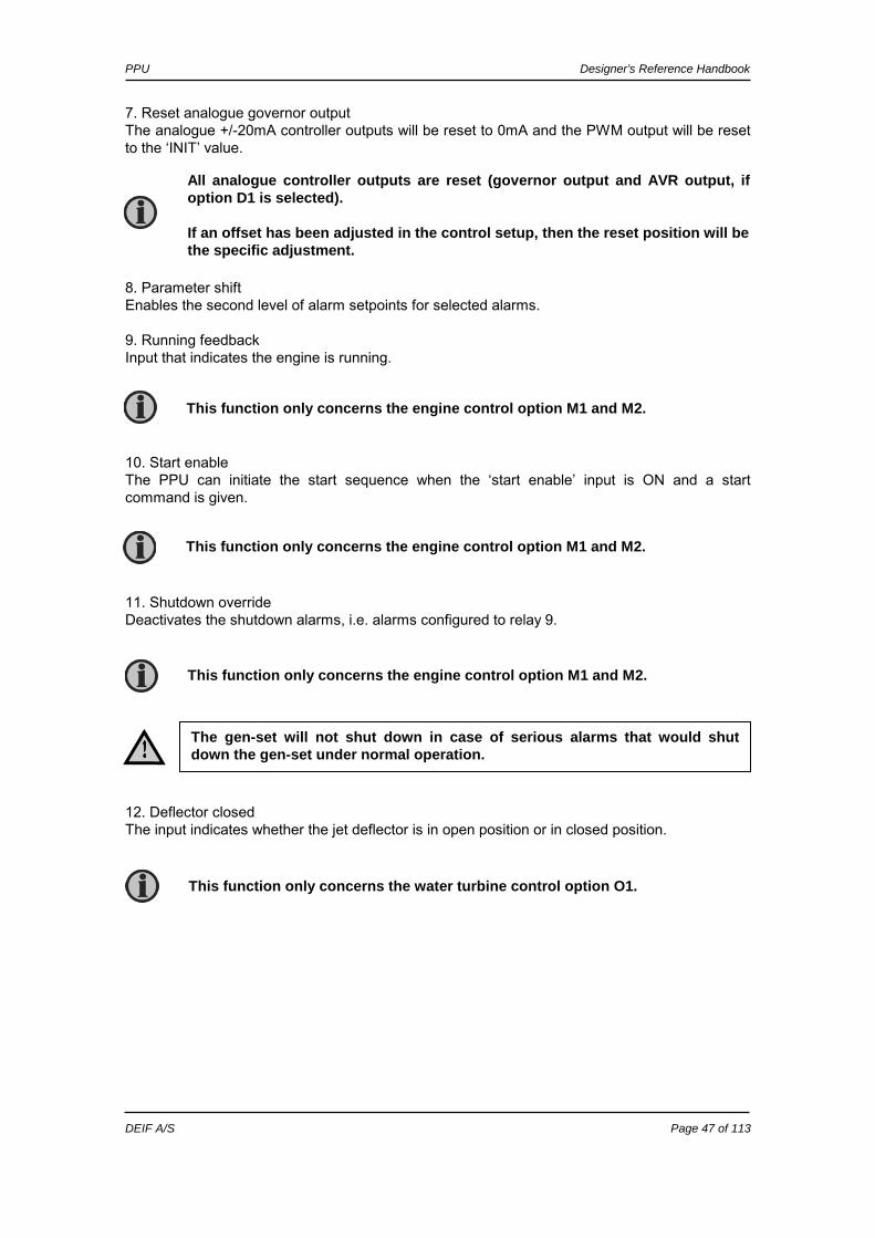
7. Reset analogue governor output The analogue +/-20mA controller outputs will be reset to 0mA and the PWM output will be reset to the ‘INIT’ value. 8. Parameter shift Enables the second level of alarm setpoints for selected alarms. 9. Running feedback Input that indicates the engine is running. 10. Start enable The PPU can initiate the start sequence when the ‘start enable’ input is ON and a start command is given. 11. Shutdown override Deactivates the shutdown alarms, i.e. alarms configured to relay 9. 12. Deflector closed The input indicates whether the jet deflector is in open position or in closed position.
All analogue controller outputs are reset (governor output and AVR output, if option D1 is selected). If an offset has been adjusted in the control setup, then the reset position will be the specific adjustment.
This function only concerns the engine control option M1 and M2.
This function only concerns the water turbine control option O1.
The gen-set will not shut down in case of serious alarms that would shut down the gen-set under normal operation.
This function only concerns the engine control option M1 and M2.
This function only concerns the engine control option M1 and M2.
PPU Designer’s Reference Handbook
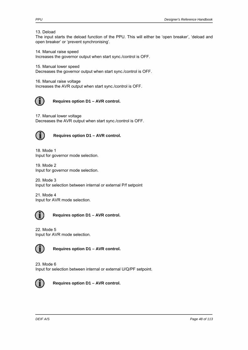
DEIF A/S Page 48 of 113
13. Deload The input starts the deload function of the PPU. This will either be ‘open breaker’, ‘deload and open breaker’ or ‘prevent synchronising’. 14. Manual raise speed Increases the governor output when start sync./control is OFF. 15. Manual lower speed Decreases the governor output when start sync./control is OFF. 16. Manual raise voltage Increases the AVR output when start sync./control is OFF. 17. Manual lower voltage Decreases the AVR output when start sync./control is OFF. 18. Mode 1 Input for governor mode selection. 19. Mode 2 Input for governor mode selection. 20. Mode 3 Input for selection between internal or external P/f setpoint 21. Mode 4 Input for AVR mode selection. 22. Mode 5 Input for AVR mode selection. 23. Mode 6 Input for selection between internal or external U/Q/PF setpoint.
Requires option D1 – AVR control.
Requires option D1 – AVR control.
Requires option D1 – AVR control.
Requires option D1 – AVR control.
Requires option D1 – AVR control.

PPU Designer’s Reference Handbook
DEIF A/S Page 49 of 113
Configuration The digital inputs are configured via the PC utility software. Select the input icon in the horizontal toolbar.
The desired input number can now be selected for the individual input function via the roll-down panel.
Alarm inputs If the digital inputs are to be used as alarm inputs they can be connected to e.g. pressure and temperature switches for alarm, trip or shutdown purposes. Since the inputs are default-configured as control inputs, it is necessary to re-configure the inputs to prepare them for the alarm use. The two possibilities for using the digital inputs are not intended to be combined. Please either use the digital input as an alarm input or as a control input. The settings in the parameter setup for the individual alarms, such as high alarm, enable or delay do not influence the control functions of the inputs.
Dedicated functions such as ‘Start enable’ can only be configured to one specific input, e.g. terminal 115 for ‘Start enable’.
If the alarm input is used without setting the control function to not used, then the control function is still active. Therefore, remember unconfiguring the control input.
PPU Designer’s Reference Handbook
DEIF A/S Page 50 of 113
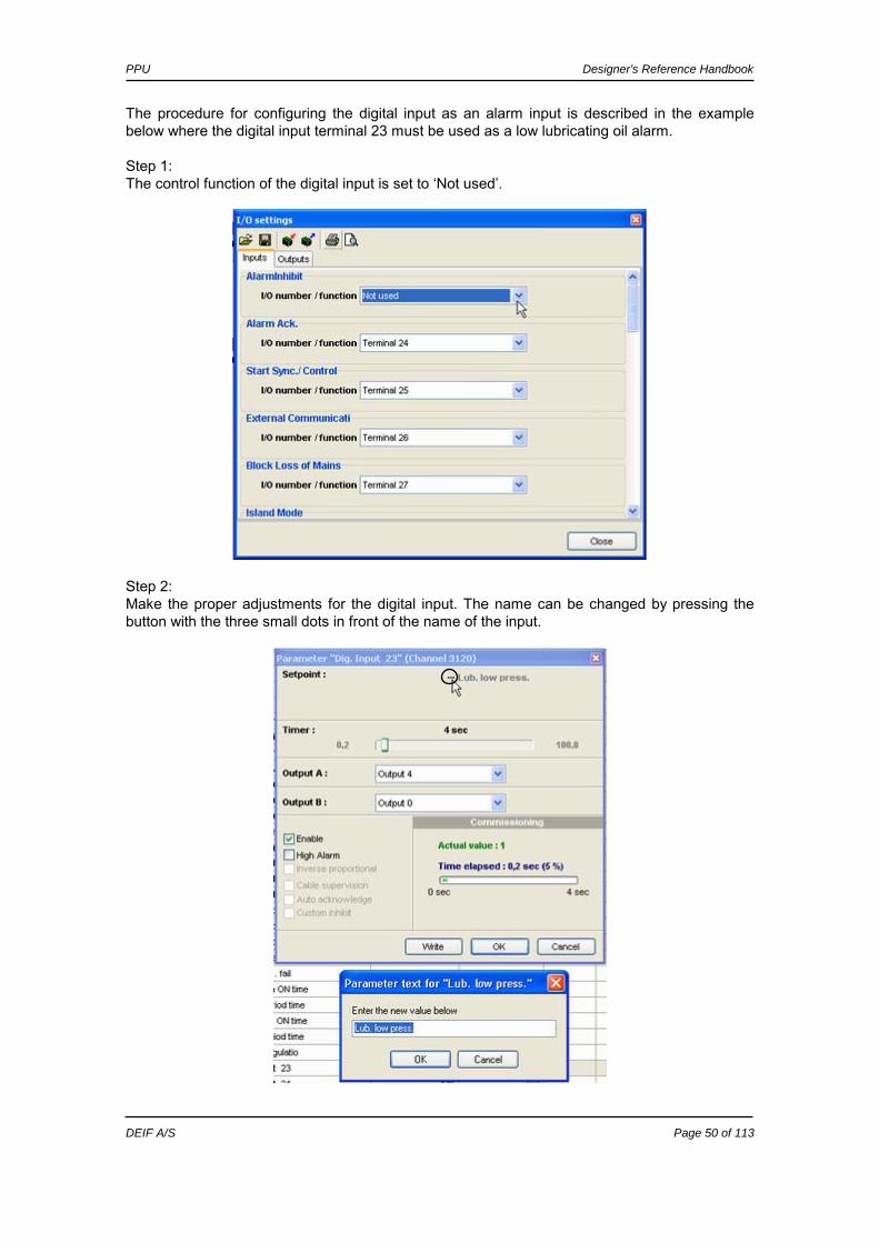
The procedure for configuring the digital input as an alarm input is described in the example below where the digital input terminal 23 must be used as a low lubricating oil alarm. Step 1: The control function of the digital input is set to ‘Not used’.
Step 2: Make the proper adjustments for the digital input. The name can be changed by pressing the button with the three small dots in front of the name of the input.
PPU Designer’s Reference Handbook
DEIF A/S Page 51 of 113
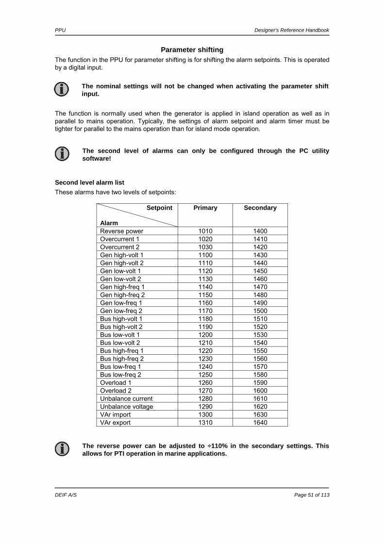
Parameter shifting The function in the PPU for parameter shifting is for shifting the alarm setpoints. This is operated by a digital input. The function is normally used when the generator is applied in island operation as well as in parallel to mains operation. Typically, the settings of alarm setpoint and alarm timer must be tighter for parallel to the mains operation than for island mode operation.
Second level alarm list These alarms have two levels of setpoints:
Setpoint Alarm
Primary Secondary
Reverse power 1010 1400 Overcurrent 1 1020 1410 Overcurrent 2 1030 1420 Gen high-volt 1 1100 1430 Gen high-volt 2 1110 1440 Gen low-volt 1 1120 1450 Gen low-volt 2 1130 1460 Gen high-freq 1 1140 1470 Gen high-freq 2 1150 1480 Gen low-freq 1 1160 1490 Gen low-freq 2 1170 1500 Bus high-volt 1 1180 1510 Bus high-volt 2 1190 1520 Bus low-volt 1 1200 1530 Bus low-volt 2 1210 1540 Bus high-freq 1 1220 1550 Bus high-freq 2 1230 1560 Bus low-freq 1 1240 1570 Bus low-freq 2 1250 1580 Overload 1 1260 1590 Overload 2 1270 1600 Unbalance current 1280 1610 Unbalance voltage 1290 1620 VAr import 1300 1630 VAr export 1310 1640
The nominal settings will not be changed when activating the parameter shift input.
The second level of alarms can only be configured through the PC utility software!
The reverse power can be adjusted to ÷110% in the secondary settings. This allows for PTI operation in marine applications.
PPU Designer’s Reference Handbook
DEIF A/S Page 52 of 113
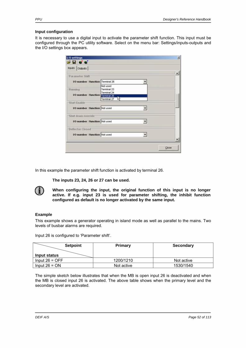
Input configuration It is necessary to use a digital input to activate the parameter shift function. This input must be configured through the PC utility software. Select on the menu bar: Settings/inputs-outputs and the I/O settings box appears.
In this example the parameter shift function is activated by terminal 26.
Example This example shows a generator operating in island mode as well as parallel to the mains. Two levels of busbar alarms are required. Input 26 is configured to ‘Parameter shift’. Setpoint Input status
Primary Secondary
Input 26 = OFF 1200/1210 Not active Input 26 = ON Not active 1530/1540 The simple sketch below illustrates that when the MB is open input 26 is deactivated and when the MB is closed input 26 is activated. The above table shows when the primary level and the secondary level are activated.
The inputs 23, 24, 26 or 27 can be used. When configuring the input, the original function of this input is no longer active. If e.g. input 23 is used for parameter shifting, the inhibit function configured as default is no longer activated by the same input.

PPU Designer’s Reference Handbook
DEIF A/S Page 53 of 113
General failure The general failure alarm (menu 2700) is defined as an alarm that occurs every time a fault is caused by abnormal and unexpected behaviour of the application. Several items are included in the general failure alarm. Description Displayed alarm text Delay Phase sequence error The phase rotations of
the generator measurements and the busbar measurements are opposite.
Phase sequence error 1 sec.
CB open failure The PPU has issued a CB open signal but the breaker has not opened.
CB open failure 1 sec.
CB close failure The PPU has issued a CB close signal but the breaker has not closed.
CB close failure 1 sec.
CB position error The PPU has neither CB open feedback nor CB closed feedback.
CB position error 1 sec.
Regulation failure The PPU has a regulation failure alarm (menu 2180 ‘GOV reg. fail.’) that occurs whenever the specific setpoint is not reached but the regulation is active. The alarm will appear when the setpoint is reached. The deviation is calculated in percent:
During general failure alarms, the regulation freezes.

PPU Designer’s Reference Handbook
DEIF A/S Page 54 of 113
Example: PACTUAL = 500 kW PSETPOINT = 800 kW Difference in percent: (800-500)/800*100 = 37.5%
The alarm occurs if this calculated value exceeds the alarm setpoint.
Inhibit The purpose of the alarm inhibit function is to avoid nuisance alarms when the generator is in a controlled operational state (stop). For example, it is not necessary to have the low voltage alarm displayed when the generator is stopped. The inhibit function can be configured in the PC utility software or the function can be used with the factory settings. The alarms are divided into five groups to make the function flexible.
Factory settings The factory setting of each group is as follows:
• BB protections: The alarms are inhibited when the circuit breaker is open. • Gen protections: The alarms are inhibited when the inhibit input is activated. • Engine I/F card: The alarms are inhibited when the inhibit input is activated. • df/dt Vector jump: The alarms are inhibited when the input ‘block loss of mains
protection’ is activated. • EIC alarms: The alarms are inhibited when the inhibit input is activated.
Possible alarms to inhibit Several of the alarms in the PPU unit can be inhibited. The alarms are split up into five groups and each group can be configured differently.
Group 1 (BB protections) Alarm Factory setting 1180 BUS high-volt 1 1190 BUS high-volt 2 1200 BUS low-volt 1 1210 BUS low-volt 2 1220 BUS high-freq 1 1230 BUS high-freq 2 1240 BUS low-freq 1 1250 BUS low-freq 2
Logic 1 And CB opened
AVR regulation failure is available if option D1 is selected.
Low as well as high level alarms can be inhibited.
The factory settings can be changed using the inhibit configurator.
Default input setting for the ‘alarm inhibit’ input is terminal 23. Default input setting for the ‘block loss of mains protection’ input is terminal 27.
PPU Designer’s Reference Handbook
DEIF A/S Page 55 of 113
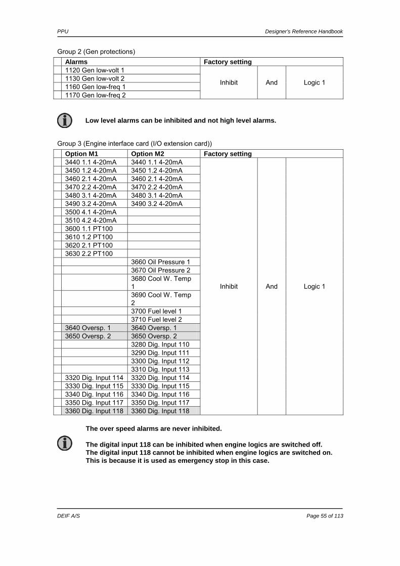
Group 2 (Gen protections) Alarms Factory setting 1120 Gen low-volt 1 1130 Gen low-volt 2 1160 Gen low-freq 1 1170 Gen low-freq 2
Inhibit And Logic 1
Group 3 (Engine interface card (I/O extension card)) Option M1 Option M2 Factory setting 3440 1.1 4-20mA 3440 1.1 4-20mA 3450 1.2 4-20mA 3450 1.2 4-20mA 3460 2.1 4-20mA 3460 2.1 4-20mA 3470 2.2 4-20mA 3470 2.2 4-20mA 3480 3.1 4-20mA 3480 3.1 4-20mA 3490 3.2 4-20mA 3490 3.2 4-20mA 3500 4.1 4-20mA 3510 4.2 4-20mA 3600 1.1 PT100 3610 1.2 PT100 3620 2.1 PT100 3630 2.2 PT100 3660 Oil Pressure 1 3670 Oil Pressure 2 3680 Cool W. Temp
1 3690 Cool W. Temp
2 3700 Fuel level 1 3710 Fuel level 2 3640 Oversp. 1 3640 Oversp. 1 3650 Oversp. 2 3650 Oversp. 2 3280 Dig. Input 110 3290 Dig. Input 111 3300 Dig. Input 112 3310 Dig. Input 113 3320 Dig. Input 114 3320 Dig. Input 114 3330 Dig. Input 115 3330 Dig. Input 115 3340 Dig. Input 116 3340 Dig. Input 116 3350 Dig. Input 117 3350 Dig. Input 117 3360 Dig. Input 118 3360 Dig. Input 118
Inhibit And Logic 1
Low level alarms can be inhibited and not high level alarms.
The over speed alarms are never inhibited. The digital input 118 can be inhibited when engine logics are switched off. The digital input 118 cannot be inhibited when engine logics are switched on. This is because it is used as emergency stop in this case.

PPU Designer’s Reference Handbook
DEIF A/S Page 56 of 113
Group 4 (df/dt – vector jump) Alarm Factory setting 1350 df/dt (ROCOF) 1360 Vector jump
Block loss of mains input And Logic 1
Group 5 (Engine interface communication) Alarm Factory setting 4800 EIC Warning 4810 EIC Shutdown 4820 EIC Overspeed 4830 EIC Coolant T.1 4840 EIC Coolant T.2 4850 EIC Oil Pres. 1 4860 EIC Oil Pres. 2
Inhibit And Logic 1
Configuration The configuration of the inhibit function is easily done using the PC Utility software. Go to ‘Settings/inhibits’ to start the configuration or press the inhibit button on the horizontal toolbar.
The dialogue box for inhibit configuration appears:
Alarm group: BB protection
Alarm group: Gen protection
Alarm group: Engine I/F card
Alarm group: df/dt Vector jump
Alarm group: Engine comm.
Condition 1 Condition 2 Ope-rator
PPU Designer’s Reference Handbook
DEIF A/S Page 57 of 113
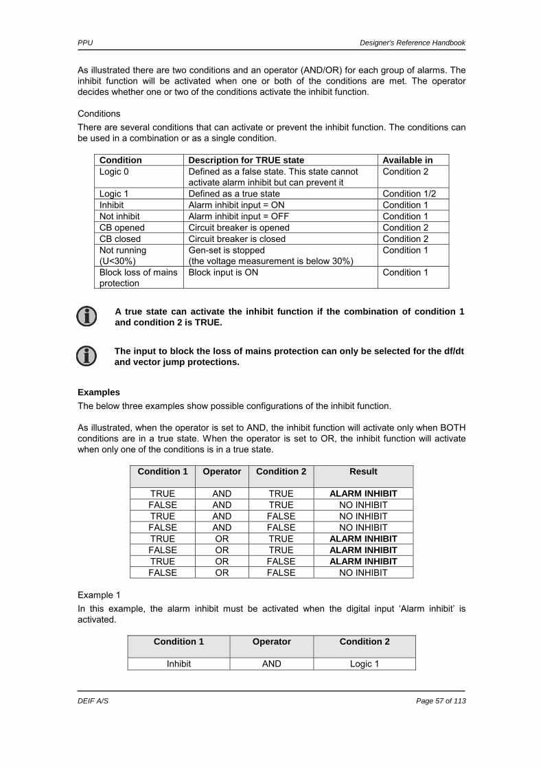
As illustrated there are two conditions and an operator (AND/OR) for each group of alarms. The inhibit function will be activated when one or both of the conditions are met. The operator decides whether one or two of the conditions activate the inhibit function.
Conditions There are several conditions that can activate or prevent the inhibit function. The conditions can be used in a combination or as a single condition.
Condition Description for TRUE state Available in Logic 0 Defined as a false state. This state cannot
activate alarm inhibit but can prevent it Condition 2
Logic 1 Defined as a true state Condition 1/2 Inhibit Alarm inhibit input = ON Condition 1 Not inhibit Alarm inhibit input = OFF Condition 1 CB opened Circuit breaker is opened Condition 2 CB closed Circuit breaker is closed Condition 2 Not running (U<30%)
Gen-set is stopped (the voltage measurement is below 30%)
Condition 1
Block loss of mains protection
Block input is ON Condition 1
Examples The below three examples show possible configurations of the inhibit function. As illustrated, when the operator is set to AND, the inhibit function will activate only when BOTH conditions are in a true state. When the operator is set to OR, the inhibit function will activate when only one of the conditions is in a true state.
Condition 1
Operator Condition 2 Result
TRUE AND TRUE ALARM INHIBIT FALSE AND TRUE NO INHIBIT TRUE AND FALSE NO INHIBIT FALSE AND FALSE NO INHIBIT TRUE OR TRUE ALARM INHIBIT FALSE OR TRUE ALARM INHIBIT TRUE OR FALSE ALARM INHIBIT FALSE OR FALSE NO INHIBIT
Example 1 In this example, the alarm inhibit must be activated when the digital input ‘Alarm inhibit’ is activated.
Condition 1
Operator Condition 2
Inhibit AND Logic 1
The input to block the loss of mains protection can only be selected for the df/dt and vector jump protections.
A true state can activate the inhibit function if the combination of condition 1 and condition 2 is TRUE.

PPU Designer’s Reference Handbook
DEIF A/S Page 58 of 113
Example 2 In this example, the alarm inhibit must be activated when the digital input ‘Alarm inhibit’ is activated or the circuit breaker is opened. Both conditions will activate the input.
Condition 1
Operator Condition 2
Inhibit OR CB opened
Example 3 In this example, the alarms must NEVER be inhibited. The result of the line below will always be FALSE and therefore the inhibit function never activates.
Condition 1
Operator Condition 2
Logic 1 AND Logic 0

PPU Designer’s Reference Handbook
DEIF A/S Page 59 of 113
Start/stop next generator The load dependent start/stop functionality uses one relay for ‘start next generator’ and one relay for ‘stop next generator’. It is also possible just to use one of the functions if it is not desired to use both the start and the stop function. The function load dependent start and stop does not give the possibilities of a power management system such as priority selection and available power calculations. This means that the switchboard manufacturer must take care of starting and stopping the next gen-set(s) and their priority. The relays can be used as inputs for the power management system as an example.
Start next generator (high load) (menu 4260) The below diagram shows that the delay for the start relay starts when the load exceeds the adjusted start limit. The relay will deactivate again when the load decreases below the start limit and the off delay has expired.
The load dependent start relay reacts based on the power measurement of the PPU together with the breaker closed feedback.
Stop next generator (low load) (menu 4270) The diagram shows that the stop relay activates after a delay. The timer starts when the load drops below the adjusted stop level, and when the delay has expired the relay activates. The relay deactivates when the load exceeds the stop level when the off delay has expired. The off delay is adjustable.
START LIMIT
Off delay Delay
Power
Time
R START activates
R START deactivates

PPU Designer’s Reference Handbook
DEIF A/S Page 60 of 113
The load dependent start relay reacts based on the power measurement of the PPU together with the breaker closed feedback.
Configuration The settings are configured through the display or through the PC utility software.
PC utility software configuration The configuration of the relays is done in 2 steps when the parameter list is uploaded from the PPU to the PC.
Step 1: Configuration of the setpoint
Open menu 4260 in the utility software and adjust the setpoint, timer and relay output.
STOP LIMIT
Delay
Power
Time
Off delay
R STOP activates R STOP deactivates
Output A and output B must be adjusted to the same relay to avoid alarms when the setpoint is reached.

PPU Designer’s Reference Handbook
DEIF A/S Page 61 of 113
Step 2: Configuration of selected relay Open the menu of the selected relay – in this example where relay 13 is used you must open menu 4730. Here, the relay function must be set to “Limit”. The purpose of this is to avoid an alarm when the relay activates.
This dialog box adjusts the off delay timer which is shown in the drawings above.
Relay allocation The four relays need to be used as follows:
• 2 relays for alarm relays • 2 relays for load dependent start/stop
The table shows a possible selection of the relays:
Relay 5 Relay 6 Relay 7 Relay 8
Load dependent START X
Load dependent STOP X
Alarm relay function X
Alarm relay function X
Start/stop scenario This diagram shows a (simplified) scenario where 3 DGs are started and stopped depending on the load dependent start/stop relays. The scenario shows that gen-set 2 starts when gen-set 1 reaches 80%. The next gen-set to start is DG3 and the three sets load share at 53%. When the load of all three gen-sets drops to the stop limit, which is 20%, then the load dependent stop relay activates and a gen-set (gen 3 in this example) can be stopped. The load continues to drop and at 20% load the next gen-set to stop is gen-set 2.

PPU Designer’s Reference Handbook
DEIF A/S Page 62 of 113
3 DG Scenario
0
10
20
30
40
50
60
70
80
90
1 2 3 4 5 6 7 8 9 10 11 12 13 14 15
Time
Pow
er [%
]
Gen 1Gen 2Gen 3
Setpoint selection There exist various principles for the PPU to control the gen-set through setpoint selection. These are internal or external setpoints or optional control via external communication.
The above is a simplified scenario.
Control via external communication is optional, Modbus (H2), Profibus(H3) or CANopen (H1).

PPU Designer’s Reference Handbook
DEIF A/S Page 63 of 113
Start
26 ON
25 ON
No
No regulationNo
50 ON
Yes
Select INTERNAL
control mode
No
Use set point from system
setup
select EXTERNAL
control mode
Yes
Activate analogue inputs (+/-10VDC)
select COMM.
control mode
Activate control register table
End
Yes
The above flowchart shows that the communication control overrules control through digital inputs. The only condition is that the communication control is activated with a digital input and then commands and setpoints can be transmitted to the PPU. If the control is done through digital inputs, then the selection between internal and external setpoint is determined by the activation of the input ‘mode 3’ (terminal 50).
The function ‘Start sync./control’ must be ON to activate the regulation. This is done through communication if the communication control is used or through digital input (terminal 25) if INTERNAL or EXTERNAL control is used.
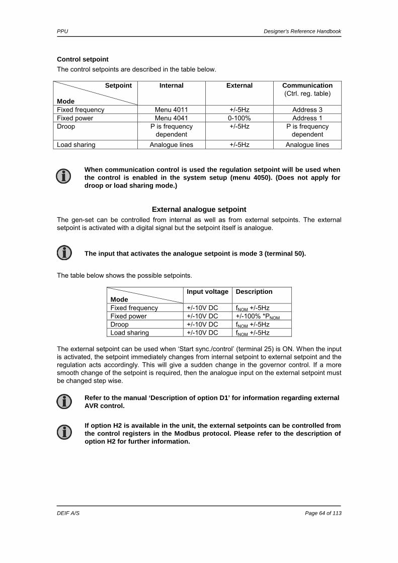
PPU Designer’s Reference Handbook
DEIF A/S Page 64 of 113
Control setpoint The control setpoints are described in the table below. Setpoint Mode
Internal External Communication (Ctrl. reg. table)
Fixed frequency Menu 4011 +/-5Hz Address 3 Fixed power Menu 4041 0-100% Address 1 Droop P is frequency
dependent +/-5Hz P is frequency
dependent Load sharing Analogue lines +/-5Hz Analogue lines
External analogue setpoint The gen-set can be controlled from internal as well as from external setpoints. The external setpoint is activated with a digital signal but the setpoint itself is analogue. The table below shows the possible setpoints.
Mode
Input voltage Description
Fixed frequency +/-10V DC fNOM +/-5Hz Fixed power +/-10V DC +/-100% *PNOM Droop +/-10V DC fNOM +/-5Hz Load sharing +/-10V DC fNOM +/-5Hz
The external setpoint can be used when ‘Start sync./control’ (terminal 25) is ON. When the input is activated, the setpoint immediately changes from internal setpoint to external setpoint and the regulation acts accordingly. This will give a sudden change in the governor control. If a more smooth change of the setpoint is required, then the analogue input on the external setpoint must be changed step wise.
The input that activates the analogue setpoint is mode 3 (terminal 50).
If option H2 is available in the unit, the external setpoints can be controlled from the control registers in the Modbus protocol. Please refer to the description of option H2 for further information.
Refer to the manual ‘Description of option D1’ for information regarding external AVR control.
When communication control is used the regulation setpoint will be used when the control is enabled in the system setup (menu 4050). (Does not apply for droop or load sharing mode.)

PPU Designer’s Reference Handbook
DEIF A/S Page 65 of 113
Load sharing The function of load sharing enables the PPU to share the active load (kW) (and reactive load (kVAr) (option D1)) equally when operating in parallel with other gen-sets. The load sharing is performed so each gen-set takes a portion of the load that is calculated in percent according to the nominal power. The load sharing is active when the load sharing mode is selected, and the generator breaker is closed.
Principle A voltage signal equal to the load produced by the gen-set is sent to the load sharing line. When the generator load is 0%, 0V DC is sent to the load share line and when the load is 100% load the voltage will be 5V DC. This is illustrated in the drawing below where the illustration indicates the characteristic of the active load sharing line. The characteristic of the reactive load sharing line is equivalent to the illustration below.
The PPU will supply a voltage on the load sharing line equal to the actual load. This voltage comes from an internal power transducer in the PPU. At the same time, the actual voltage on the load sharing line will be measured by the PPU.
If the measured voltage is higher than the voltage from the internal power transducer, then the PPU will increase its load in order to match the voltage on the load sharing line.
Power Reverse power
100% load
5V DC
-5V DC
Load sharing line
V DC
-100% load
PPU Designer’s Reference Handbook
DEIF A/S Page 66 of 113
If the measured voltage is lower than the voltage from the internal power transducer, then the PPU will decrease its load in order to match the voltage on the load sharing line.
The voltage on the load sharing line will only be different from the voltage from the internal power transducer, if two or more Multi-line 2 units are connected to the load share line. For the same reason it is not necessary to change between load sharing mode and fixed frequency mode if the PPU is installed in an island mode application where the operation changes between stand-alone and load sharing mode. Then the mode inputs can be hardwired.
Examples These examples show that generators will balance their load depending on the signal on the load sharing line.
Example 1: Two generators are running in parallel. The loads of the generators are:
Generator Actual load Voltage on load sharing line Generator 1 100% 5V DC Generator 2 0% 0V DC
The voltage level on the load sharing line can be calculated to:
ULS: (5 + 0)/2 = 2.5V DC Now generator 1 will decrease the load in order to match the voltage on the load sharing line (in this example 2.5V DC). Generator 2 will increase the load in order to match the 2.5V DC. The new load share situation will be:
Generator Actual load Voltage on load sharing line Generator 1 50% 2.5V DC Generator 2 50% 2.5V DC
Example 2: In case of generators of different size, the load sharing will still be carried out on the basis of a percentage of the nominal power. Two generators supply the busbar. The total load is 550kW.
Generator Nominal power Actual load Voltage on load sharing line Generator 1 1000kW 500kW 2.5V DC Generator 2 100kW 50kW 2.5V DC
Both generators are supplying 50% of their nominal power.
Ramp up function In the menu 2144 it is possible to enable a power ramp up function in the PPU when it is operating in load sharing mode. When this function is enabled, the PPU will not balance the load immediately when the breaker is closed but will follow the adjusted power ramp up curve (menu 2141). This means that the other generator(s) will carry the majority of the load during the time where the actual generator is in its ramp up sequence.

PPU Designer’s Reference Handbook
DEIF A/S Page 67 of 113
The power setpoint is still reflecting the reference on the load sharing line (0-5V DC ~ 0-100%). When the generator has reached the setpoint, it follows the load without further ramp functions. The (load sharing mode) ramp function is initiated when LS mode is selected and the CB closes, or when the deload input (43) changes state.
Load sharing/NO RAMP This diagram shows how the load balances after breaker closing when the ramp function (in load sharing mode) is deactivated. The load is balanced immediately, followed by load sharing between the two DGs.
Load sharing/RAMP FUNCTION ON This picture shows a situation after the breaker closes and where the ramp function is activated. When DG 2 synchronises, it loads up following the ramp curve. Any variations in load will in principle be taken by DG 1, until the ramp sequence has ended. In this diagram no delay point is used (timer 2143 = 0 sec).
If the ramp up delay point (menu 2142) is used, the actual power production during the delay period (menu 2143) will not match the adjusted value exactly. This is because the regulator setpoint is a mix between the power and frequency controllers when operating in load sharing mode.

PPU Designer’s Reference Handbook
DEIF A/S Page 68 of 113
Distance The inputs on the PPU that are used for load sharing are high impedance inputs (23.5 kOhm) so a cable length of 300 meters is no problem.
Load sharing type The output from the PPU is by default adjusted to match other Multi-line 2 and Uni-line products from DEIF A/S. This selection enables the load share output to operate in the 5V DC range. If the load share type is changed to ‘adjustable’ (menu 4250) then the voltage level can be changed in the range 1.0 – 5.0V DC (menu 4240). The advantage of this is that the load share output can be connected to or compared with other systems.
If the load share type is changed to ‘Selco T4800’, the voltage level of the load share line adapts to the required level of the Selco T4800.
Modes active The PPU is designed to control the generator before, during and after synchronising. However, in rare cases it may become necessary to deactivate the regulation after the synchronising. This can be the case e.g. if other load sharing equipment is installed or if an external power factor controller is installed. Adjust this in menu 2110.
Principle The diagrams below show that the regulation is active until the circuit breaker closes (during synchronising). When the circuit breaker closes, the regulation will only be active for the selected controller, the governor, the automatic voltage regulator or none of them.
Example 1, menu 2110 is adjusted to ‘Sync+GOV+AVR’
Remember to always use screened cable.
Careful testing must be carried out when different load sharing systems are interconnected. The reason is that not all systems can be interconnected and still function properly.
The regulation will always be active when the circuit breaker is open. It is only possible to stop the regulation when the circuit breaker is closed.
The display shows ‘No regulation’ if the regulation is stopped due to the ‘Modes active’ function.

PPU Designer’s Reference Handbook
DEIF A/S Page 69 of 113
Example 2, menu 2110 is adjusted to ‘Sync+GOV’
Example 3, menu 2110 is adjusted to ‘SYNC’
Synchronising window On certain occasions it is necessary to automatically stop the synchronising of the gen-set if the mains voltage changes to unacceptable limits. This can be achieved with the function synchronising window (menu 2050). The function is typically used when the generator is intended for parallel operation with the mains and the mains is unstable in voltage. E.g. when the generator manufacturer recommends not regulating the voltage beyond certain limits, then the function can be used.
Description When the synchronising is started, the PPU will normally regulate the generator frequency and voltage towards the busbar frequency and voltage. This is necessary because the individual generator controller can only control its own generator and not the other generators/mains connected to the busbar.
The same function as 2110 = ‘SYNC’ can also be achieved by deactivating terminal 25, ‘Start sync./Control’ when the circuit breaker closes.
This function is active when the CB is open. The function requires a relay output on the PPU.

PPU Designer’s Reference Handbook
DEIF A/S Page 70 of 113
On locations where the mains is unstable or not very rigid, the mains voltage will drop from time to time. When the busbar voltage falls below the limit, the regulation is stopped and the synchronising is temporarily interrupted. The regulation and synchronising will be re-started when the busbar voltage increases above the adjusted setpoint.
Diagram The diagram below illustrates that the relay output of the PPU activates when the busbar voltage decreases below the setpoint. There is a short timer setting with the purpose of allowing a short voltage dip without interrupting the control.
Relay output It is not necessary to connect the relay output from the PPU to anything. The only purpose of the relay output is to let the function be active without getting an alarm. If an alarm occurs anyway then either output A (menu 2053) or output B (menu 2054) is not configured to a limit relay.
The mains voltage is measured by the PPU on its ‘busbar’ inputs. In the following, the mains will be referred to as busbar.
Both the frequency and the voltage regulations are stopped when the limit is reached.
Adjust output A and output B in the menu settings to a limit relay. This is necessary to avoid an alarm when the busbar voltage is out of the accepted range.

PPU Designer’s Reference Handbook
DEIF A/S Page 71 of 113
Relay setup The PPU has several relay outputs available. Each of these relays can be given a special function depending on the required functionality. This is done in the system setup (menu 4600 -4760).
Relay functions There are five functions available. (Please refer to the Horn output chapter for information regarding the horn function as it is not covered in this chapter. See p. 71.) Function Description
Alarm The relay is activated until the alarm that caused the activation is acknowledged and gone. The alarm LED is flashing or constant depending on the acknowledged state.
Alarm + sync. block The relay is activated until the alarm that caused the activation is acknowledged and gone. When the relay is activated, the synchronising is blocked but the regulation is still active.
Limit
The relay will activate at the limit setpoint. No alarm will appear when both outputs (OA/OB) of the alarm are adjusted to the limit relay. After the condition activating this relay has returned to normal, the relay will deactivate when the “Off delay” has expired. The OFF delay is adjustable.
Alarm/reset The functionality is similar to ‘Alarm’, but with a short-time reset if the relay is ON and another alarm tries to activate the same relay.
Alarm sync. block/reset
The functionality is similar to ‘Alarm + sync. Block’, but with a short-time reset if the relay is ON and another alarm tries to activate the same relay.
Horn output Relay #3 (terminals 11, 12, 13) can be chosen to be a horn output. This is selected in the menu 4590. This means that the relay can be connected to an alarm annunciator, e.g. a horn. Every time a new alarm occurs, the horn output will activate. The horn output will activate on all alarms. The output remains activated until:
• The alarm is acknowledged • The horn relay timer runs out (automatic reset function)
When relay 3 is activated to be the horn relay, it cannot be used by anything else.
The horn output will not activate on limit switch functions.
PPU Designer’s Reference Handbook
DEIF A/S Page 72 of 113
Automatic reset The horn relay function has an automatic reset function. When the timer (menu 4591) is adjusted differently from 0 second, then the horn relay output resets itself when the delay has expired. This is also the situation when the alarm is STILL present.
Manual reset If the time is set to 0.0 s, the automatic reset of the horn output is disabled. The horn will remain ON until the alarm is acknowledged by the operator. Now, the status of the alarm changes from un-acknowledged (UN-ACK.) to acknowledged (ACK.)
Trip characteristics The alarms in the PPU controller are typically with definite time characteristics. This means that when the alarm setpoint is exceeded, then the delay will expire and the alarm occurs. For certain alarms the inverse trip characteristic can be selected. An inverse characteristic means that the alarm delay setpoint is dependent on the specific exceeding of the setpoint. A small exceeding means that a long time will pass until the alarm occurs whereas a bigger exceeding of the setpoint means that a shorter time will pass until the alarm occurs.
Possible alarms The table shows that the reverse power alarm and one over current alarm can be adjusted with inverse trip characteristic. Characteristic Alarm
Definite Inverse
1010 Reverse power X X 1020 Overcurrent 1 X - 1030 Overcurrent 2 X - 1060 Overcurr. inv. X X
Reverse power If inverse characteristic is selected, the tripping time is dependent on how much the setpoint is exceeded. The PPU will calculate the exact tripping time depending on the alarm settings. The alarm settings define a certain amount of energy that defines the longest possible tripping time. When the setpoint is exceeded, the measured energy is calculated according to the setpoint (1011) and the time delay (1012). If this value is exceeded, the alarm occurs. The maximum energy (kWh) will never be exceeded, so if the reverse power increases, the time delay will decrease and vice versa.
The horn output resets when the alarm is still present. This is the function of the ‘Automatic reset’.
If the alarm condition is gone when the alarm is acknowledged, then the specific alarm message also disappears.
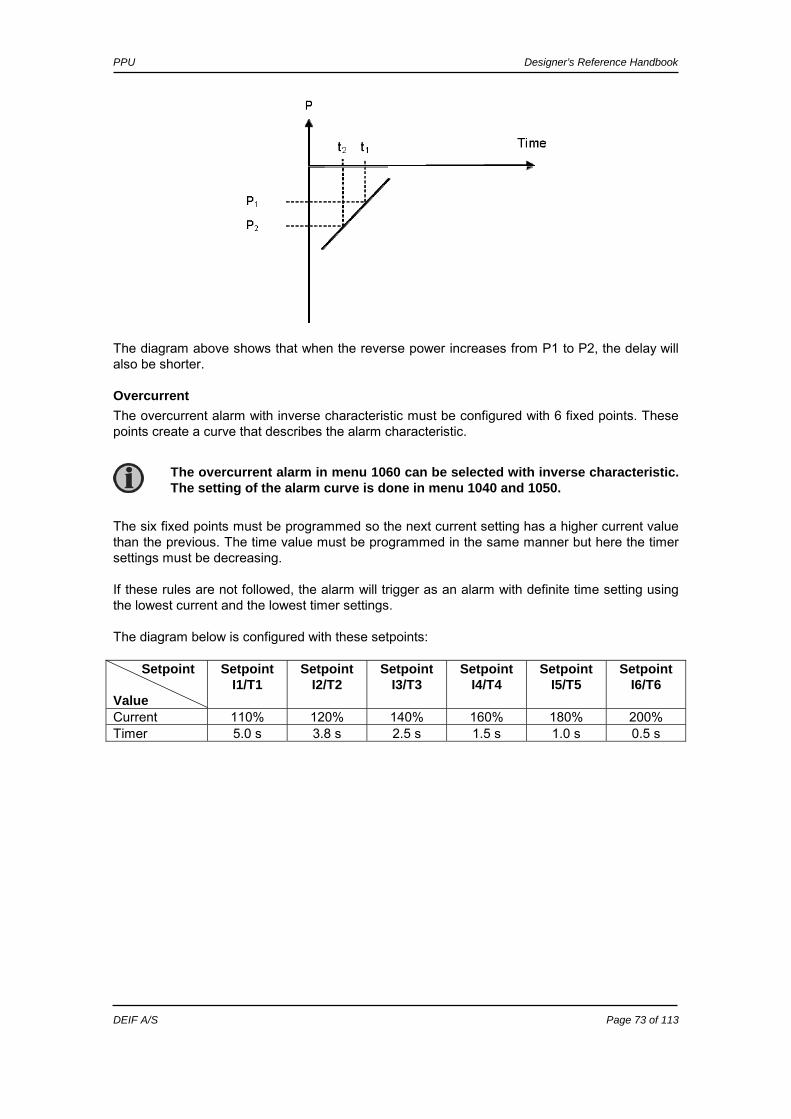
PPU Designer’s Reference Handbook
DEIF A/S Page 73 of 113
The diagram above shows that when the reverse power increases from P1 to P2, the delay will also be shorter.
Overcurrent The overcurrent alarm with inverse characteristic must be configured with 6 fixed points. These points create a curve that describes the alarm characteristic. The six fixed points must be programmed so the next current setting has a higher current value than the previous. The time value must be programmed in the same manner but here the timer settings must be decreasing. If these rules are not followed, the alarm will trigger as an alarm with definite time setting using the lowest current and the lowest timer settings. The diagram below is configured with these setpoints: Setpoint Value
Setpoint I1/T1
Setpoint I2/T2
Setpoint I3/T3
Setpoint I4/T4
Setpoint I5/T5
Setpoint I6/T6
Current 110% 120% 140% 160% 180% 200% Timer 5.0 s 3.8 s 2.5 s 1.5 s 1.0 s 0.5 s
The overcurrent alarm in menu 1060 can be selected with inverse characteristic. The setting of the alarm curve is done in menu 1040 and 1050.
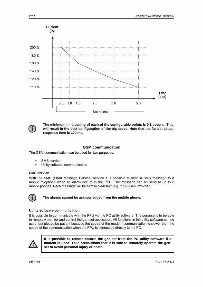
PPU Designer’s Reference Handbook
DEIF A/S Page 74 of 113
Current (%)
Set points
5.0 3.6 2.5 1.5 1.0 0.5
Time (sec)
110 %
120 %
140 %
160 %
180 %
200 %
GSM communication The GSM communication can be used for two purposes.
• SMS service • Utility software communication
SMS service With the SMS (Short Message Service) service it is possible to send a SMS message to a mobile telephone when an alarm occurs in the PPU. The message can be send to up to 5 mobile phones. Each message will be sent in clear text, e.g. ‘1120 Gen low-volt 1’.
Utility software communication It is possible to communicate with the PPU via the PC utility software. The purpose is to be able to remotely monitor and control the gen-set application. All functions in the utility software can be used, but please be patient because the speed of the modem communication is slower than the speed of the communication when the PPU is connected directly to the PC.
The alarms cannot be acknowledged from the mobile phone.
It is possible to remote control the gen-set from the PC utility software if a modem is used. Take precautions that it is safe to remotely operate the gen-set to avoid personal injury or death.
The minimum time setting of each of the configurable points is 0.1 second. This will result in the best configuration of the trip curve. Note that the fastest actual response time is 200 ms.

PPU Designer’s Reference Handbook
DEIF A/S Page 75 of 113
Principle overview It is possible to use the SMS service or the utility software communication. This is illustrated below.
Wirings and connections
Serial connection The serial connection to the GSM modem is done via straight cable (option J1) (male/female).
Modem DEIF A/S recommends using the MOXA OnCell G2150I, Wavecom WMOD2 or Westermo GDW-11 terminal, as the application has been tested with these terminals. The easiest way to get the modem is to purchase it through a local dealer. A SIM card must be fitted in the modem. The SIM card can be purchased from the local telephone company. Setting the PIN code on the SIM card of the modem is done easily by inserting the SIM in a mobile telephone and then by changing the PIN code there. Should an alarm occur during the interruption, the PPU will retransmit the SMS message when the modem starts again. This secures that no messages are lost.
Multi-line
Modem
Service port
Mobilephone
SMS alarmmessage
Telephoneline
PC with Utili ty Software
RS232connection
The SIM card must support data transfer for PC utility software communication. This is not necessary if only SMS service is needed.
The PIN code of the SIM card must also be adjusted in parameter file (menu 5116).
Some modem manufacturers recommend a short power interruption (30 seconds) once a day to prevent lock-up of the modem. This is easily done using a 24h watch.

PPU Designer’s Reference Handbook
DEIF A/S Page 76 of 113
SMS setup To enable the SMS service, the PPU must be configured in the PC utility software. When the parameter list is uploaded from the PPU, then the telephone number(s) and PIN code can be adjusted. The display cannot be used for this configuration.
Parameter no.
Text Factory setting
5111 Telephone no. 1 12345678901 5112 Telephone no. 2 12345678902 5113 Telephone no. 3 12345678903 5114 Telephone no. 4 12345678904 5115 Telephone no. 5 12345678905 5116 PIN code 1933
When the parameter file is opened, the configuration can be done by double clicking the specific menu number. In the example below, menu 5111 must be configured.
Utility software communication setup The service port is used for the communication between the modem and the PPU. The principle of the communication of the service port must be changed to ASCII mode when the modem communication is used.
Add mobile telephone number here
Enable the mobile telephone number here
To call a foreign number type ‘+ country code’ instead of ‘00’, for example dial +45 99999999 for a Danish number.
The PIN code is transmitted to the modem when the PPU initialises and again each time an SMS message is transmitted.

PPU Designer’s Reference Handbook
DEIF A/S Page 77 of 113
Display configuration Use the ‘JUMP’ push-button to go to the menu 6020 and change the selection to 1. (default selection is 0)
PC configuration Press the settings symbol on the horizontal toolbar (the hammer).
Check off the box as indicated below and press OK. Now ASCII mode is selected.
Modem selection When ‘Modem’ is selected in the dialogue box above, the modem configurations can be made.
Selection ‘1’ means ASCII communication which is needed for the modem communication.
If the PPU and the USW is adjusted to ASCII mode it is still possible to communicate directly from the PC service port to the PPU.

PPU Designer’s Reference Handbook
DEIF A/S Page 78 of 113
Select the modem and key in the telephone number of the GSM modem connected to the PPU. Now the PC can connect through the modem when the telephone button on the horizontal toolbar is pressed.
Download precaution If the communication fails during parameter download, the Multi-line unit will operate according to the received data. If e.g. only half of the parameter file has been downloaded, when the communication is interrupted, the settings are going to be a mix and the PPU will act accordingly.
Step up transformer The PPU can be used in applications where the generator is followed by a step up transformer. I.e. the measurement of the generator voltage is on a different level than the measurement of the busbar voltage. The functions available in this application are:
1. Synchronising with or without phase compensation 2. Voltage measurements displayed 3. Generator protections (option dependent) 4. Busbar protections (option dependent)
Applications Different applications are supported by the PPU when a step up transformer is placed after a generator. Measurement transformers can be installed on the generator side and the busbar side, or direct inputs between 100V AC and 690V AC can be connected. A typical setup includes a low voltage generator, e.g. 400V AC, and a step up transformer, e.g. 400/10000V AC. In this case, 400V AC would be connected to the generator inputs and 100 or
The modem communication is much slower than the normal direct connection so please be patient. It is not recommended to download the entire parameter list. Use the ‘Write’ function instead.
The maximum nominal voltage supported by the PPU is 25000V AC.
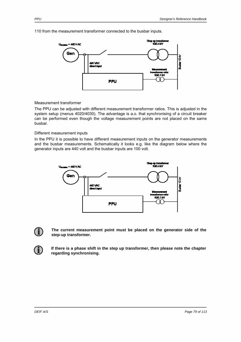
PPU Designer’s Reference Handbook
DEIF A/S Page 79 of 113
110 from the measurement transformer connected to the busbar inputs.
Measurement transformer The PPU can be adjusted with different measurement transformer ratios. This is adjusted in the system setup (menus 4020/4030). The advantage is a.o. that synchronising of a circuit breaker can be performed even though the voltage measurement points are not placed on the same busbar.
Different measurement inputs In the PPU it is possible to have different measurement inputs on the generator measurements and the busbar measurements. Schematically it looks e.g. like the diagram below where the generator inputs are 440 volt and the busbar inputs are 100 volt.
The current measurement point must be placed on the generator side of the step-up transformer.
If there is a phase shift in the step up transformer, then please note the chapter regarding synchronising.
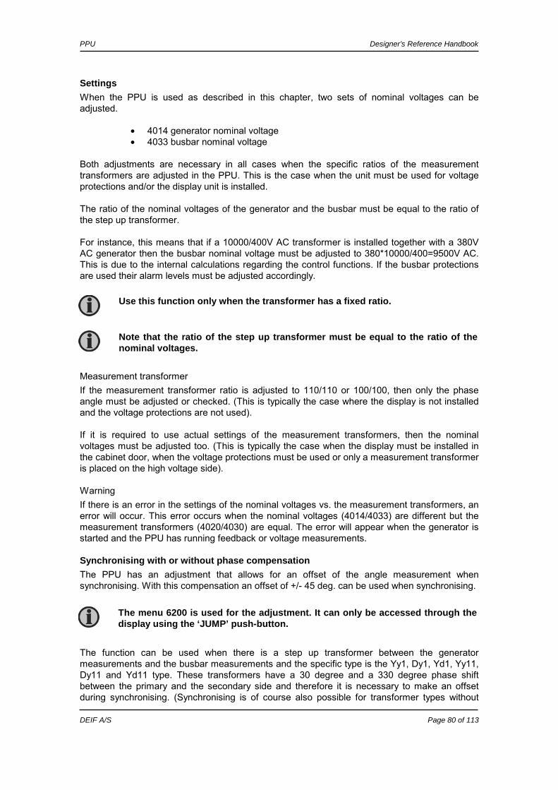
PPU Designer’s Reference Handbook
DEIF A/S Page 80 of 113
Settings When the PPU is used as described in this chapter, two sets of nominal voltages can be adjusted.
• 4014 generator nominal voltage • 4033 busbar nominal voltage
Both adjustments are necessary in all cases when the specific ratios of the measurement transformers are adjusted in the PPU. This is the case when the unit must be used for voltage protections and/or the display unit is installed. The ratio of the nominal voltages of the generator and the busbar must be equal to the ratio of the step up transformer. For instance, this means that if a 10000/400V AC transformer is installed together with a 380V AC generator then the busbar nominal voltage must be adjusted to 380*10000/400=9500V AC. This is due to the internal calculations regarding the control functions. If the busbar protections are used their alarm levels must be adjusted accordingly.
Measurement transformer If the measurement transformer ratio is adjusted to 110/110 or 100/100, then only the phase angle must be adjusted or checked. (This is typically the case where the display is not installed and the voltage protections are not used). If it is required to use actual settings of the measurement transformers, then the nominal voltages must be adjusted too. (This is typically the case when the display must be installed in the cabinet door, when the voltage protections must be used or only a measurement transformer is placed on the high voltage side).
Warning If there is an error in the settings of the nominal voltages vs. the measurement transformers, an error will occur. This error occurs when the nominal voltages (4014/4033) are different but the measurement transformers (4020/4030) are equal. The error will appear when the generator is started and the PPU has running feedback or voltage measurements.
Synchronising with or without phase compensation The PPU has an adjustment that allows for an offset of the angle measurement when synchronising. With this compensation an offset of +/- 45 deg. can be used when synchronising. The function can be used when there is a step up transformer between the generator measurements and the busbar measurements and the specific type is the Yy1, Dy1, Yd1, Yy11, Dy11 and Yd11 type. These transformers have a 30 degree and a 330 degree phase shift between the primary and the secondary side and therefore it is necessary to make an offset during synchronising. (Synchronising is of course also possible for transformer types without
The menu 6200 is used for the adjustment. It can only be accessed through the display using the ‘JUMP’ push-button.
Use this function only when the transformer has a fixed ratio.
Note that the ratio of the step up transformer must be equal to the ratio of the nominal voltages.

PPU Designer’s Reference Handbook
DEIF A/S Page 81 of 113
angle displacement).
Single line example The simple diagram below shows a step up transformer with +/- 30 deg phase shift depending on the type of transformer. In order to be able to synchronise the generator circuit breaker, the PPU must compensate for the 30 degree offset.
When used for synchronising, the PPU uses the ratio of the nominal voltages of the generator and the busbar when calculating the AVR setpoint and the voltage synchronising window (dUMAX).
Example: A 10000/400V AC step up transformer is installed after a generator with the nominal voltage of 400V AC. The nominal voltage of the busbar is 10000V AC. Now, the voltage of the busbar is 10500V AC. The generator is running 400V AC before the synchronising starts but when attempting to synchronise the AVR setpoint will be changed to UBUS-
MEASURED * UGEN-NOM/UBUS-NOM :10500*400/10000 = 420V AC.
The factory setting is 0 degrees and it has to remain at that value except when one of the six mentioned transformers is installed between the generator and the busbar measurements.
If the transformer has an angle displacement, then synchronising can ONLY be used with Yy1, Dy1, Yd1, Yy11, Dy11 and Yd11 transformers. (+/-30 deg. phase shift).
Any error in this setting will cause a false closing of the breaker! Therefore it is essential to check the angular precision before allowing the PPU to perform a real breaker closing.
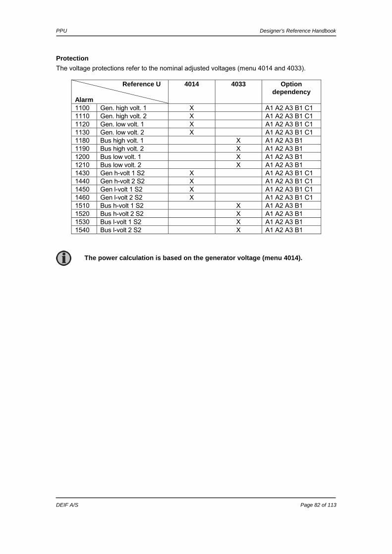
PPU Designer’s Reference Handbook
DEIF A/S Page 82 of 113
Protection The voltage protections refer to the nominal adjusted voltages (menu 4014 and 4033).
Reference U Alarm
4014 4033 Option dependency
1100 Gen. high volt. 1 X A1 A2 A3 B1 C1 1110 Gen. high volt. 2 X A1 A2 A3 B1 C1 1120 Gen. low volt. 1 X A1 A2 A3 B1 C1 1130 Gen. low volt. 2 X A1 A2 A3 B1 C1 1180 Bus high volt. 1 X A1 A2 A3 B1 1190 Bus high volt. 2 X A1 A2 A3 B1 1200 Bus low volt. 1 X A1 A2 A3 B1 1210 Bus low volt. 2 X A1 A2 A3 B1 1430 Gen h-volt 1 S2 X A1 A2 A3 B1 C1 1440 Gen h-volt 2 S2 X A1 A2 A3 B1 C1 1450 Gen l-volt 1 S2 X A1 A2 A3 B1 C1 1460 Gen l-volt 2 S2 X A1 A2 A3 B1 C1 1510 Bus h-volt 1 S2 X A1 A2 A3 B1 1520 Bus h-volt 2 S2 X A1 A2 A3 B1 1530 Bus l-volt 1 S2 X A1 A2 A3 B1 1540 Bus l-volt 2 S2 X A1 A2 A3 B1
The power calculation is based on the generator voltage (menu 4014).

PPU Designer’s Reference Handbook
DEIF A/S Page 83 of 113
7. PI controller The unit controller is a PI controller. It consists of a proportional regulator and an integral regulator. The PI controller is able to eliminate the regulation deviation and can easily be tuned in.
Controllers There are two controllers for the governor control, and, if option D1 is selected, also two controllers for the AVR control.
Controller GOV AVR Comment
Frequency X Controls the frequency Power X Controls the power Voltage (option D1) X Controls the voltage VAr (option D1) X Controls the VAr’s or power factor
The table below indicates when each of the controllers is active. This means that the controllers can be tuned in when the shown running situations are present. Governor AVR (option
dependent) Schematic
Frequency Power Voltage VAr
X X
X X
X X
X X X X
The frequency (and voltage) controller is activated when the gen-set is running in island operation, stand-alone or load sharing mode. The power (and VAr) controller is activated when the gen-set is running parallel to the mains or in load sharing mode.
G
GB MB
G
GB MB
G
GB MB
G
G
GB
GB
See ‘General Guidelines for Commissioning’.
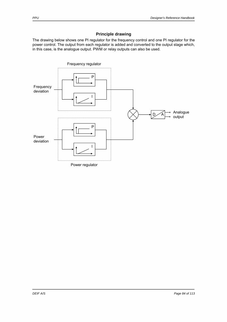
PPU Designer’s Reference Handbook
DEIF A/S Page 84 of 113
Principle drawing The drawing below shows one PI regulator for the frequency control and one PI regulator for the power control. The output from each regulator is added and converted to the output stage which, in this case, is the analogue output. PWM or relay outputs can also be used.
D A
P
I
I
P
Frequency deviation
Power deviation
Analogue output
Frequency regulator
Power regulator

PPU Designer’s Reference Handbook
DEIF A/S Page 85 of 113
Proportional regulator When the regulation deviation occurs, the proportional part will cause an immediate change of the output. The size of the change depends on the proportional action coefficient, KP. The diagram shows how the output of the P regulator depends on the KP setting. The change of the output at a given KP setting will be doubled if the regulation deviation doubles.
P-regulator
0
200
400
600
800
1000
1200
0 5 10 15 20 25 30
mA
kP
8%
4%
2%
1% 0,5%
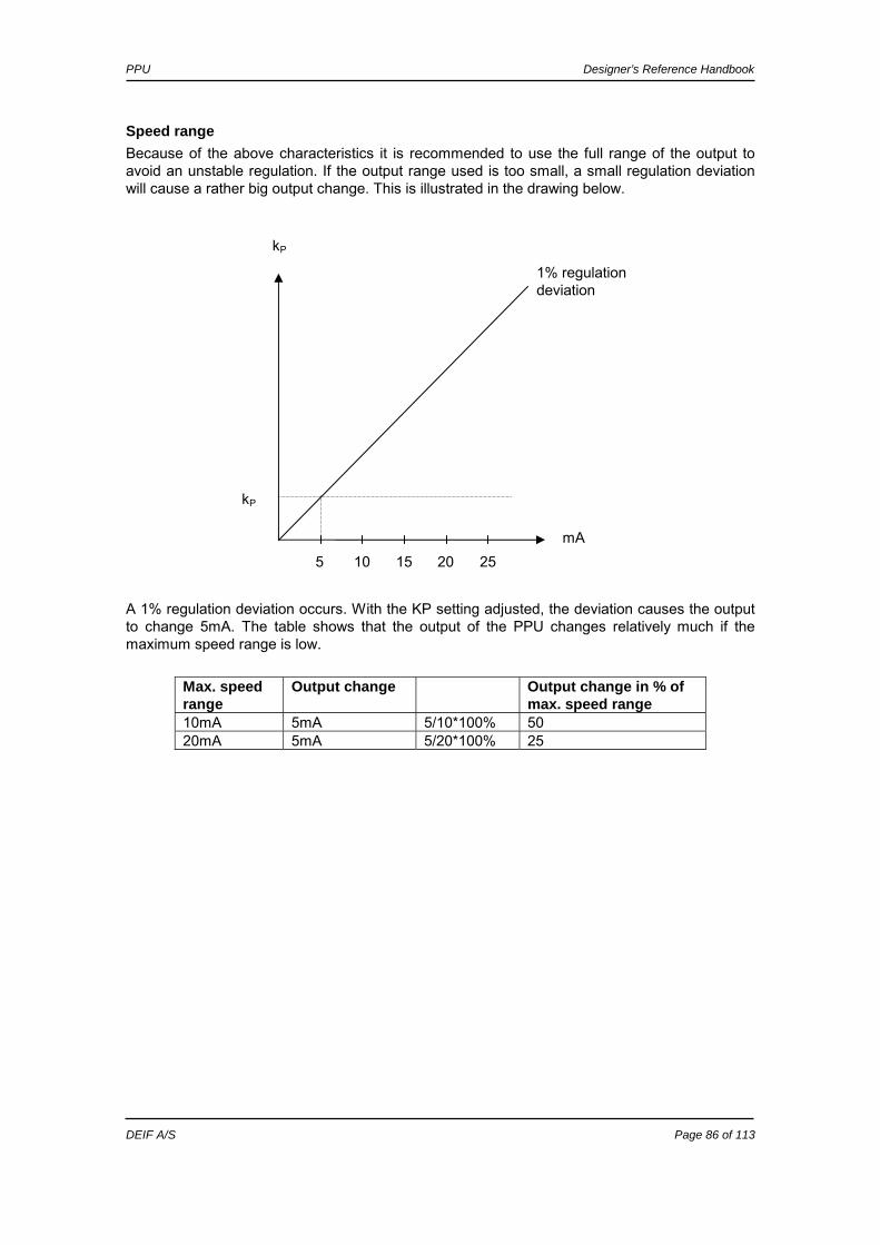
PPU Designer’s Reference Handbook
DEIF A/S Page 86 of 113
Speed range Because of the above characteristics it is recommended to use the full range of the output to avoid an unstable regulation. If the output range used is too small, a small regulation deviation will cause a rather big output change. This is illustrated in the drawing below.
A 1% regulation deviation occurs. With the KP setting adjusted, the deviation causes the output to change 5mA. The table shows that the output of the PPU changes relatively much if the maximum speed range is low.
Max. speed range
Output change Output change in % of max. speed range
10mA 5mA 5/10*100% 50 20mA 5mA 5/20*100% 25
1% regulation deviation
5 20 mA
kP
10 25 15
kP

PPU Designer’s Reference Handbook
DEIF A/S Page 87 of 113
Dynamic regulation area The drawing below shows the dynamic regulation area at given values of KP. The dynamic area is reduced if the KP is adjusted to a higher value.
Dynamic regulation band
-30
-20
-10
0
10
20
30
44 45 46 47 48 49 50 51 52 53 54 55 56
Frequency
mA
KP = 1000
KP = 100
KP = 10

PPU Designer’s Reference Handbook
DEIF A/S Page 88 of 113
Integral regulator To illustrate the integral action coefficient, the KI reset time can be used. The reset time is defined as the time the integral regulator uses to replicate the momentary change of the output caused by the proportional regulator. In the drawing below, the proportional regulator causes an immediate change of 2.5mA. The reset time is then measured when the output reaches 2 x 2.5mA = 5mA. The drawing shows that when the KI setting is changed to half the value, then the reset time is doubled. The reset time is 10 seconds with a KI setting of 100. With the KI setting adjusted to 50 the reset time will be 20 seconds. The KP setting is 100 in this example. The reset time of the unit can be calculated at all values of KP and KI with the formula: The table shows theoretical reset times in seconds:
kI kP
1
10
100
1000
1 10 1 0.1 0.01 10 100 10 1 0.1 100 1000 100 10 1 1000 10000 1000 100 10
Reset time, tN
0
1
2
3
4
5
6
0 5 10 15 20 25 30 35
sec
mA
KI = 100 KI = 50
IP kktN /10*=

PPU Designer’s Reference Handbook
DEIF A/S Page 89 of 113
The integrating function of the I regulator is increased if the integral action coefficient, KI, is increased. This means that the reset time is reduced and a faster I regulation is achieved. If the KI is adjusted to 0 (reset time endless), the I regulator is switched off.
Relay control When the relay outputs are used for control purposes, the regulation works like this:
The regulation with relays can be split up into five steps. # Range Description Comment 1 Static range Fix up signal The regulation is active, but the increase relay will be
constantly activated because of the size of the regulation deviation.
2 Dynamic range
Up pulse The regulation is active, and the increase relay will be pulsing in order to eliminate the regulation deviation.
3 Dead band area
No reg. In this particular range no regulation takes place. The regulation accepts a predefined dead band area in order to increase the lifetime of the relays.
4 Dynamic range
Down pulse The regulation is active, and the decrease relay will be pulsing in order to eliminate the regulation deviation.
5 Static range Fix down signal The regulation is active, but the decrease relay will be constantly activated because of the size of the regulation deviation.
55Hz 45Hz 50Hz
Regulator output
Fix up signal Up pulse No reg. Fix down signal Down pulse
Hz
The integral action coefficient, KI, must not be too high. This will make the regulation hunt similar to a too high proportional action factor, KP.

PPU Designer’s Reference Handbook
DEIF A/S Page 90 of 113
As the drawing indicates, the relays will be fixed on if the regulation deviation is big, and they will be pulsing if it is closer to the setpoint. In the dynamic range, the pulses get shorter and shorter when the regulation deviation gets smaller. Just before the dead band area, the pulse is as short as it can be. This is the adjusted time ‘GOV ON time’/(’AVR ON time’). The longest pulse will appear at the end of the dynamic range (45Hz in the example above).
Relay adjustments The time settings for the regulation relays can be adjusted in the control setup. It is possible to adjust the ‘period’ time and the ‘ON’ time. They are shown on the drawing below. Adjustment Description Comment Period time Maximum relay time The time between the beginning of two
subsequent relay pulses. ON time Minimum relay time The minimum length of the relay pulse. The
relays will never be activated for a shorter time than the ON time.
As indicated in the drawing below, the length of the relay pulse will depend on the actual regulation deviation. If the deviation is big, the pulses will be long (or a continued signal). If the deviation is small, the pulses will be short.
ON ON ON ONON
PERIOD PERIOD PERIOD PERIOD PERIOD
t [sec]
Relay ON
HIGH <DEVIATION> LOW

PPU Designer’s Reference Handbook
DEIF A/S Page 91 of 113
Signal length The signal length is calculated compared to the adjusted period time. In the below drawing, the effect of the proportional regulator is indicated.
In this example, we have a 2 percent regulation deviation and an adjusted value of the KP = 200. The calculated regulator value of the unit is 40%. Now, the pulse length can be calculated with a period time = 2500 ms: The length of the period time will never be shorter than the adjusted ON time. The P regulator causes the relay output to activate. The I regulator has the same effect on the relay output as described on page 84 concerning the reset time tN.
P-regulator
0
200
400
600
800
1000
1200
0 20 40 60 80 100 120
regulator value
kP
8%
4%
2%
1% 0,5%
mste PERIODDEVIATION
10002500*100/40*100/=

PPU Designer’s Reference Handbook
DEIF A/S Page 92 of 113
8. Synchronisation The unit can be used for synchronisation of generator and mains breaker (if installed). Two different synchronisation principles are available, namely static and dynamic synchronisation (dynamic is selected by default). This chapter describes the principles of the synchronisation functions and the adjustment of them.
Dynamic synchronisation In dynamic synchronisation, the synchronising gen-set is running at a different speed than the generator on the busbar. This speed difference is called slip frequency. Typically, the synchronising gen-set is running with a positive slip frequency. This means that it is running with a higher speed than the generator on the busbar. The objective is to avoid a reverse power trip after the synchronisation. The dynamic principle is illustrated below.
L2
2.5 s 7.5 s5.0 s 0 s
GBGB
Load
Synchronised
L1 L1L1L1L1
L3 L2 L2 L2L2 L3 L3L3L3L3
L1
L1 L2
L2
L3
L3 L1
∆t [s]
180°
90° 0°
Angle L1gen/L1bus
[deg]
Synchronising generator Generator on load
Synchronisation principle - dynamic synchronisation
1503 RPM 50.1 Hertz
Speed:
1500 RPM 50.00 Hertz
Speed:
L2
In the following, the term ‘synchronisation’ means ‘synchronising and closing of the synchronised breaker’.

PPU Designer’s Reference Handbook
DEIF A/S Page 93 of 113
In the above example, the synchronising gen-set is running at 1503 RPM ~ 50.1Hz. The generator on load is running at 1500 RPM ~ 50.0Hz. This gives the synchronising gen-set a positive slip frequency of 0.1Hz. The intention of the synchronising is to decrease the phase angle difference between the two rotating systems. These two systems are the three-phase system of the generator and the three-phase system of the busbar. On the illustration above phase L1 of the busbar is always pointing at 12 o’clock, whereas phase L1 of the synchronising gen-set is pointing in different directions due to the slip frequency. When the generator is running with a positive slip frequency of 0.1Hz compared to the busbar, then the two systems will be synchronised every 10 seconds. In the above illustration, the difference in the phase angle between the synchronising set and the busbar gets smaller and will eventually be zero. Then the gen-set is synchronised to the busbar, and the breaker will be closed.
Close signal The unit always calculates when to close the breaker to get the most accurate synchronisation. This means that the close breaker signal is actually issued before being synchronised (read L1 phases exactly at 12 o’clock). The breaker close signal will be issued depending on the breaker closing time and the slip frequency (response time of the circuit breaker is 250 ms, and the slip frequency is 0.1Hz): The length of the synchronisation pulse is the response time + 20 ms.
Load picture after synchronising When the incoming gen-set has closed its breaker, it will take a portion of the load depending on the actual position of the fuel rack. Illustration 1 below indicates that at a given positive slip frequency, the incoming gen-set will export power to the load. Illustration 2 below shows that at a given negative slip frequency, the incoming gen-set will receive power from the original gen-set. This phenomenon is called reverse power.
Of course, both three-phase systems are rotating, but for illustrative purposes the vectors for the generator on load are not shown to be rotating. The reason is that we are only interested in the slip frequency for calculating when to release the synchronisation pulse.
sec100.501.50
1 =−
=SYNCt
deg9deg1.0*250.0*360deg
**360deg
===
CLOSE
CLOSE
SLIPCBCLOSE ft
The synchronisation pulse is always issued, so the closing of the breaker will occur at the 12 o’clock position.
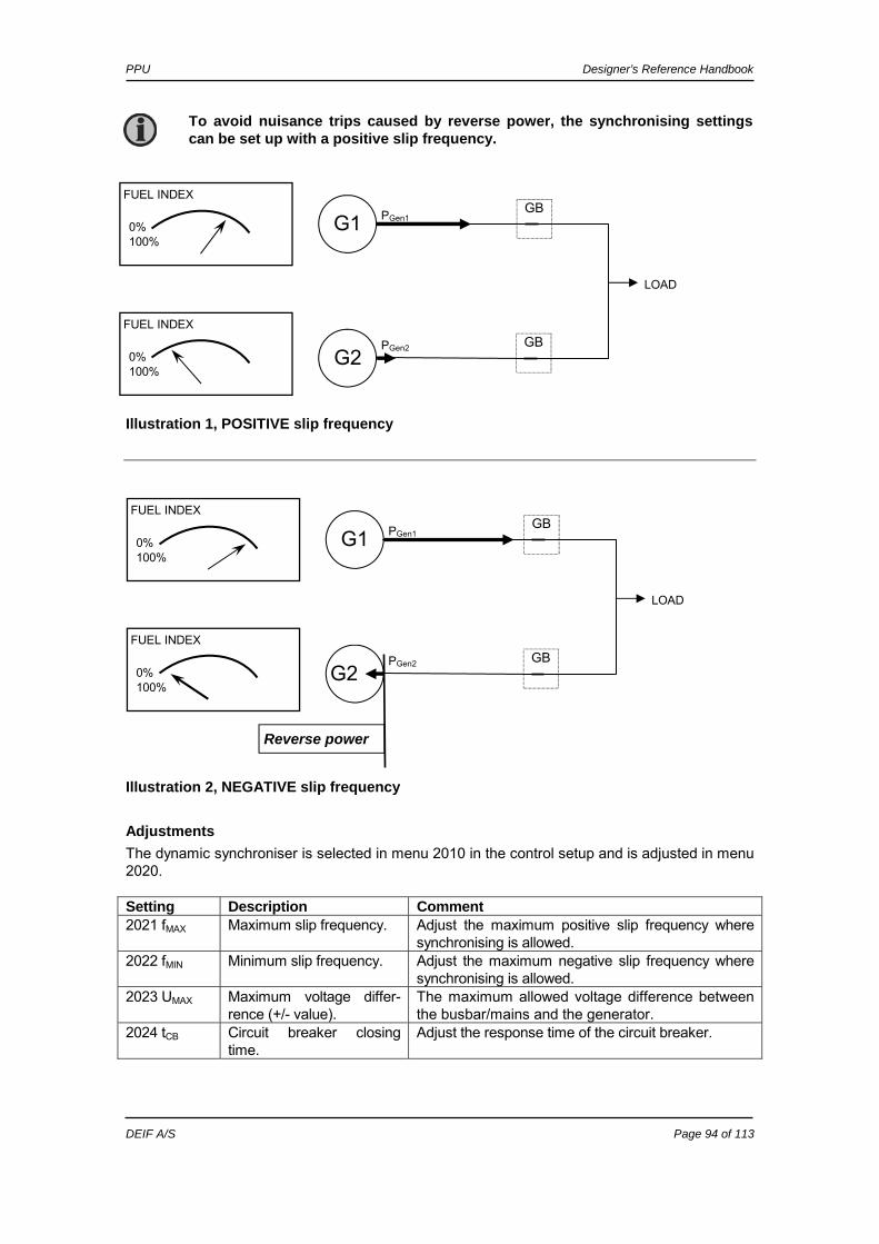
PPU Designer’s Reference Handbook
DEIF A/S Page 94 of 113
Illustration 1, POSITIVE slip frequency
Illustration 2, NEGATIVE slip frequency
Adjustments The dynamic synchroniser is selected in menu 2010 in the control setup and is adjusted in menu 2020. Setting Description Comment 2021 fMAX Maximum slip frequency. Adjust the maximum positive slip frequency where
synchronising is allowed. 2022 fMIN Minimum slip frequency. Adjust the maximum negative slip frequency where
synchronising is allowed. 2023 UMAX Maximum voltage differ-
rence (+/- value). The maximum allowed voltage difference between the busbar/mains and the generator.
2024 tCB Circuit breaker closing time.
Adjust the response time of the circuit breaker.
0% 100%
PGen2
FUEL INDEX
FUEL INDEX
0% 100%
G1
G2 GB
GB
LOAD
PGen1
0% 100%
PGen2
FUEL INDEX
FUEL INDEX
0% 100%
G1
G2 GB
GB
LOAD
PGen1
Reverse power
To avoid nuisance trips caused by reverse power, the synchronising settings can be set up with a positive slip frequency.
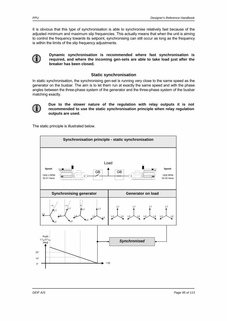
PPU Designer’s Reference Handbook
DEIF A/S Page 95 of 113
It is obvious that this type of synchronisation is able to synchronise relatively fast because of the adjusted minimum and maximum slip frequencies. This actually means that when the unit is aiming to control the frequency towards its setpoint, synchronising can still occur as long as the frequency is within the limits of the slip frequency adjustments.
Static synchronisation In static synchronisation, the synchronising gen-set is running very close to the same speed as the generator on the busbar. The aim is to let them run at exactly the same speed and with the phase angles between the three-phase system of the generator and the three-phase system of the busbar matching exactly. The static principle is illustrated below.
L1
GBGB
Load
Synchronised
L1 L1 L1L1L1
L1L1
L2 L2L2 L2 L2L2L2 L3 L3L3L3L3 L3 L3 L3
t [s]
20°
10° 0°
Angle L1gen/L1bus
[deg]
Synchronising generator Generator on load
Synchronisation principle - static synchronisation
1500.3 RPM 50.01 Hertz
Speed:
1500 RPM 50.00 Hertz
Speed:
α α α
L2
Dynamic synchronisation is recommended where fast synchronisation is required, and where the incoming gen-sets are able to take load just after the breaker has been closed.
Due to the slower nature of the regulation with relay outputs it is not recommended to use the static synchronisation principle when relay regulation outputs are used.
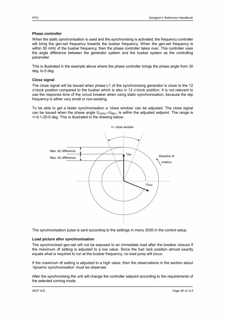
PPU Designer’s Reference Handbook
DEIF A/S Page 96 of 113
Phase controller When the static synchronisation is used and the synchronising is activated, the frequency controller will bring the gen-set frequency towards the busbar frequency. When the gen-set frequency is within 50 mHz of the busbar frequency, then the phase controller takes over. This controller uses the angle difference between the generator system and the busbar system as the controlling parameter. This is illustrated in the example above where the phase controller brings the phase angle from 30 deg. to 0 deg.
Close signal The close signal will be issued when phase L1 of the synchronising generator is close to the 12 o’clock position compared to the busbar which is also in 12 o’clock position. It is not relevant to use the response time of the circuit breaker when using static synchronisation, because the slip frequency is either very small or non-existing. To be able to get a faster synchronisation a ‘close window’ can be adjusted. The close signal can be issued when the phase angle UGENL1-UBBL1 is within the adjusted setpoint. The range is +/-0.1-20.0 deg. This is illustrated in the drawing below.
The synchronisation pulse is sent according to the settings in menu 2030 in the control setup.
Load picture after synchronisation The synchronised gen-set will not be exposed to an immediate load after the breaker closure if the maximum df setting is adjusted to a low value. Since the fuel rack position almost exactly equals what is required to run at the busbar frequency, no load jump will occur. If the maximum df setting is adjusted to a high value, then the observations in the section about ‘dynamic synchronisation’ must be observed. After the synchronising the unit will change the controller setpoint according to the requirements of the selected running mode.
Max. dU difference
Max. dU difference Direction of
rotation
+/- close window
UBB
UGEN
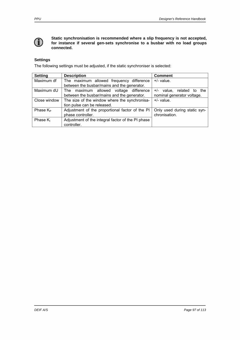
PPU Designer’s Reference Handbook
DEIF A/S Page 97 of 113
Settings The following settings must be adjusted, if the static synchroniser is selected: Setting Description Comment Maximum df The maximum allowed frequency difference
between the busbar/mains and the generator. +/- value.
Maximum dU The maximum allowed voltage difference between the busbar/mains and the generator.
+/- value, related to the nominal generator voltage.
Close window The size of the window where the synchronisa-tion pulse can be released.
+/- value.
Phase KP Adjustment of the proportional factor of the PI phase controller.
Phase KI Adjustment of the integral factor of the PI phase controller.
Only used during static syn-chronisation.
Static synchronisation is recommended where a slip frequency is not accepted, for instance if several gen-sets synchronise to a busbar with no load groups connected.

PPU Designer’s Reference Handbook
DEIF A/S Page 98 of 113
9. Procedure for parameter setup This chapter deals with the procedure to be followed when the parameters of the unit are set up from the initial point of finding the individual parameter description in this handbook to the actual setup. By use of various illustrations the following will guide the user through the whole procedure for parameter setup step by step.
Finding the selected parameter The first step in the parameter setup is finding the correct parameter descriptions. All parameter descriptions are located in chapter 10 ‘Parameter setup’ which is intended for reference purposes. The descriptions are structured according to their parameter titles and the main parameter group to which they belong. Find the individual parameter title in the overview list on page 102.
In the overview list you will find the page location of the parameter description you are looking for.
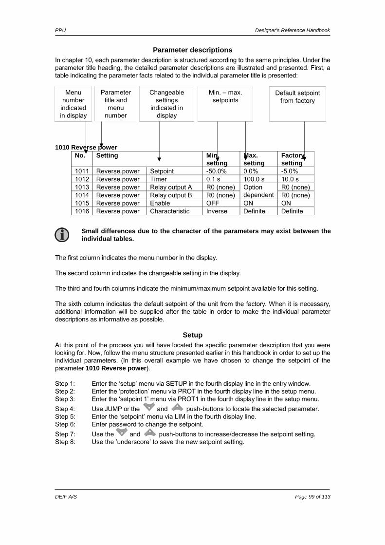
PPU Designer’s Reference Handbook
DEIF A/S Page 99 of 113
Parameter descriptions In chapter 10, each parameter description is structured according to the same principles. Under the parameter title heading, the detailed parameter descriptions are illustrated and presented. First, a table indicating the parameter facts related to the individual parameter title is presented:
1010 Reverse power
No. Setting Min. setting
Max. setting
Factory setting
1011 Reverse power Setpoint -50.0% 0.0% -5.0% 1012 Reverse power Timer 0.1 s 100.0 s 10.0 s 1013 Reverse power Relay output A R0 (none) R0 (none) 1014 Reverse power Relay output B R0 (none)
Option dependent R0 (none)
1015 Reverse power Enable OFF ON ON 1016 Reverse power Characteristic Inverse Definite Definite
The first column indicates the menu number in the display. The second column indicates the changeable setting in the display. The third and fourth columns indicate the minimum/maximum setpoint available for this setting. The sixth column indicates the default setpoint of the unit from the factory. When it is necessary, additional information will be supplied after the table in order to make the individual parameter descriptions as informative as possible.
Setup At this point of the process you will have located the specific parameter description that you were looking for. Now, follow the menu structure presented earlier in this handbook in order to set up the individual parameters. (In this overall example we have chosen to change the setpoint of the parameter 1010 Reverse power). Step 1: Enter the ‘setup’ menu via SETUP in the fourth display line in the entry window. Step 2: Enter the ‘protection’ menu via PROT in the fourth display line in the setup menu. Step 3: Enter the ‘setpoint 1’ menu via PROT1 in the fourth display line in the setup menu. Step 4: Use JUMP or the and push-buttons to locate the selected parameter. Step 5: Enter the ‘setpoint’ menu via LIM in the fourth display line. Step 6: Enter password to change the setpoint. Step 7: Use the and push-buttons to increase/decrease the setpoint setting. Step 8: Use the ’underscore’ to save the new setpoint setting.
Menu number
indicated in display
Changeable settings
indicated in display
Min. – max. setpoints
Default setpoint from factory
Parameter title and menu
number
Small differences due to the character of the parameters may exist between the individual tables.

PPU Designer’s Reference Handbook
DEIF A/S Page 100 of 113
10. Parameter setup This chapter includes a complete standard parameter list. Therefore, this part of the handbook is to be used for reference when specific information about the individual parameters is needed for the unit setup. An overview list can be seen on the next page. Parameter table description The table consists of the following possible adjustments: Setpoint: The alarm setpoint is adjusted in the setpoint menu. The setting is a
percentage of the nominal values. Timer: The timer setting is the time that must expire from the alarm level is reached
until the alarm occurs. Relay output A: A relay can be activated by output A. Relay output B: A relay can be activated by output B. Enable: The alarm can be activated or deactivated. It is also possible to configure the parameters by using the PC utility software. It will be possible to make the same configurations as described above.
The parameter lists for the available options are presented in the documents Description of Options describing the individual options in detail.
Small differences due to the character of the parameters may exist between the individual tables.

PPU Designer’s Reference Handbook
DEIF A/S Page 101 of 113
By using the PC utility software some extra functionalities are available. For all the protections it is possible to make an automatic acknowledgement of the alarm. Usually it is important when the mains protections are used, as the sequences are blocked until the alarm is acknowledged.

PPU Designer’s Reference Handbook
DEIF A/S Page 102 of 113
Overview list Protection 3230 Binary input 49 p. 108 1010 Reverse power p. 103 3240 Binary input 50 p. 108 1020 Over current 1 p. 103 3250 Binary input 51 p. 108 1030 Over current 2 p. 103 3260 Binary input 52 p. 109 1040 Over current inv. p. 103 3270 Binary input 53 p. 109 1050 Over current inv. p. 103 1060 Over current inverse p. 104 System 4010 Nominal settings p. 109 Control 4020 Transformer gen. p. 109 2010 Synchronisation type p. 104 4030 Transformer bus p. 109 2020 Dynamic sync. p. 104 4040 Controller p. 109 2030 Static sync. p. 104 4100 Date and time p. 110 2040 Sync. black out p. 104 4121 Counters p. 110 2050 Sync. window p. 104 4221 Battery low voltage p. 110 2060 Sync. failure p. 105 4230 Language p. 110 2070 General failure p. 105 4240 Load share out p. 110 2110 Modes active p. 105 4250 Load share type p. 110 2120 Frequency control p. 105 4260 Start next gen. p. 110 2130 Power control p. 105 4270 Stop next gen. p. 111 2140 Power ramp up p. 105 4590 Horn p. 111 2150 Power ramp down p. 106 4600 Relay 0 (Virtual) p. 111 2180 Governor regulation failure p. 106 4610 Relay 1 p. 111 2250 Relay control p. 106 4620 Relay 2 p. 111 2290 Delay regulation p. 106 4630 Relay 3 p. 111 4640 Relay 4 p. 111 Input 4650 Relay 5 p. 112 3120 Binary input 23 p. 106 4660 Relay 6 p. 112 3130 Binary input 24 p. 106 4670 Relay 7 p. 112 3140 Binary input 25 p. 107 4680 Relay 8 p. 112 3150 Binary input 26 p. 107 4940 Generator Type p. 112 3160 Binary input 27 p. 107 3170 Binary input 43 p. 107 Jump button 3180 Binary input 44 p. 107 4971 User password p. 112 3190 Binary input 45 p. 107 4972 YYYYY password p. 113 3200 Binary input 46 p. 108 4980 Service menu p. 113 3210 Binary input 47 p. 108 6100 Application p. 113 3220 Binary input 48 p. 108 6200 Phase compensation p. 113
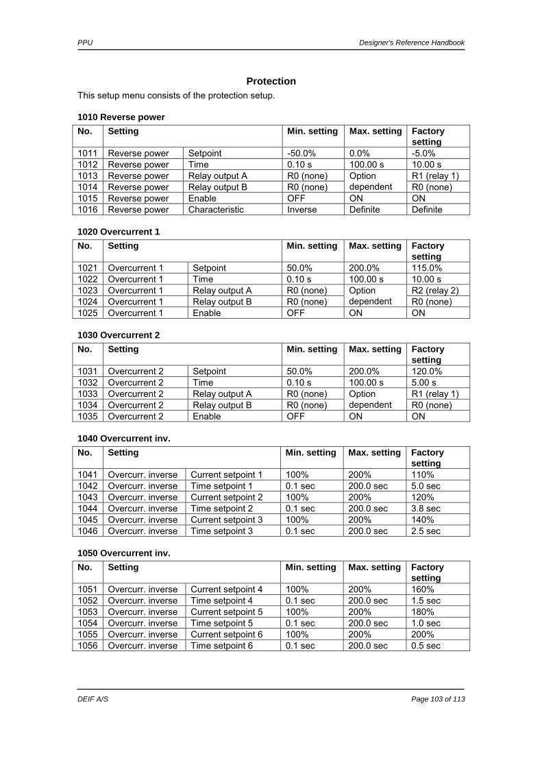
PPU Designer’s Reference Handbook
DEIF A/S Page 103 of 113
Protection This setup menu consists of the protection setup.
1010 Reverse power No. Setting Min. setting Max. setting Factory
setting 1011 Reverse power Setpoint -50.0% 0.0% -5.0% 1012 Reverse power Time 0.10 s 100.00 s 10.00 s 1013 Reverse power Relay output A R0 (none) R1 (relay 1) 1014 Reverse power Relay output B R0 (none)
Option dependent R0 (none)
1015 Reverse power Enable OFF ON ON 1016 Reverse power Characteristic Inverse Definite Definite
1020 Overcurrent 1 No. Setting Min. setting Max. setting Factory
setting 1021 Overcurrent 1 Setpoint 50.0% 200.0% 115.0% 1022 Overcurrent 1 Time 0.10 s 100.00 s 10.00 s 1023 Overcurrent 1 Relay output A R0 (none) R2 (relay 2) 1024 Overcurrent 1 Relay output B R0 (none)
Option dependent R0 (none)
1025 Overcurrent 1 Enable OFF ON ON
1030 Overcurrent 2 No. Setting Min. setting Max. setting Factory
setting 1031 Overcurrent 2 Setpoint 50.0% 200.0% 120.0% 1032 Overcurrent 2 Time 0.10 s 100.00 s 5.00 s 1033 Overcurrent 2 Relay output A R0 (none) R1 (relay 1) 1034 Overcurrent 2 Relay output B R0 (none)
Option dependent R0 (none)
1035 Overcurrent 2 Enable OFF ON ON
1040 Overcurrent inv. No. Setting Min. setting Max. setting Factory
setting 1041 Overcurr. inverse Current setpoint 1 100% 200% 110% 1042 Overcurr. inverse Time setpoint 1 0.1 sec 200.0 sec 5.0 sec 1043 Overcurr. inverse Current setpoint 2 100% 200% 120% 1044 Overcurr. inverse Time setpoint 2 0.1 sec 200.0 sec 3.8 sec 1045 Overcurr. inverse Current setpoint 3 100% 200% 140% 1046 Overcurr. inverse Time setpoint 3 0.1 sec 200.0 sec 2.5 sec
1050 Overcurrent inv. No. Setting Min. setting Max. setting Factory
setting 1051 Overcurr. inverse Current setpoint 4 100% 200% 160% 1052 Overcurr. inverse Time setpoint 4 0.1 sec 200.0 sec 1.5 sec 1053 Overcurr. inverse Current setpoint 5 100% 200% 180% 1054 Overcurr. inverse Time setpoint 5 0.1 sec 200.0 sec 1.0 sec 1055 Overcurr. inverse Current setpoint 6 100% 200% 200% 1056 Overcurr. inverse Time setpoint 6 0.1 sec 200.0 sec 0.5 sec

PPU Designer’s Reference Handbook
DEIF A/S Page 104 of 113
1060 Overcurrent inverse No. Setting Min. setting Max. setting Factory
setting 1061 Overcurr. inverse Relay output A R0 (none) R1 (relay 1) 1062 Overcurr. inverse Relay output B R0 (none)
Option dependent R1 (relay 1)
1063 Overcurr. inverse Activate OFF ON ON
Control This setup menu consists of the synchronisation setup and the regulation setup.
2010 Synchronisation type No. Setting First setting Second
setting Factory setting
2011 Sync. type Sync. type Static sync. Dynamic sync.
Dynamic sync.
2020 Dynamic sync. No. Setting Min. setting Max. setting Factory
setting 2021 Dynamic sync. Df max. 0.0Hz 0.5Hz 0.3Hz 2022 Dynamic sync. Df min. -0.5Hz 0.5Hz 0.0Hz 2023 Dynamic sync. DU max. 2% 10% 5% 2024 Dynamic sync. Breaker delay 40 ms 300 ms 50 ms
2030 Static sync. No. Setting Min. setting Max. setting Factory
setting 2031 Static sync. Maximum df 0.00Hz 1.00Hz 0.25Hz 2032 Static sync. Maximum dU 2% 10% 5% 2033 Static sync. Close window 0.1 deg. 20.0 deg. 10.0 deg. 2034 Static sync. Phase KP 0 1000 10 2035 Static sync. Phase KI 0 1000 160
2040 Sync. black out No. Setting Min. setting Max. setting Factory
setting 2041 Sync. blackout Df max. 0.0Hz 5.0Hz 3.0Hz 2042 Sync. blackout DU max. 2% 10% 5% 2043 Sync. blackout Enable OFF ON OFF
2050 Sync. window No. Setting Min. setting Max. setting Factory
setting 2051 Sync. window Setpoint +/- 2.0% 20.0% 15.0% 2052 Sync. window Delay 0.1 s 2.0 s 0.5 s 2053 Sync. window Output A R0 (none) R0 (none) 2054 Sync. window Output B R0 (none)
Option dependent R0 (none)
2055 Sync. window Enable OFF ON OFF

PPU Designer’s Reference Handbook
DEIF A/S Page 105 of 113
2060 Sync. failure No. Setting Min. setting Max. setting Factory
setting 2061 Sync. failure Delay 30.0 s 300.0 s 60.0 s 2062 Sync. failure Relay output A R0 (none) R2 (relay 2) 2063 Sync. failure Relay output B R0 (none)
Option dependent R0 (none)
2064 Sync. failure Activate OFF ON ON
2070 General failure No. Setting Min. setting Max. setting Factory
setting 2071 General failure Relay output A R0 (none) R2 (relay 2) 2072 General failure Relay output B R0 (none)
Option dependent R0 (none)
2074 General failure Activate OFF ON ON
2110 Modes active No. Setting Description Factory
setting PC software setting
2111 Modes active Sync. + gov. + AVR All modes All modes 0 Modes active Sync. + gov. Only gov. 1 Modes active Sync. + AVR Only AVR 2 Modes active Sync. Only sync. 3
2120 Frequency control No. Setting Min. setting Max. setting Factory
setting 2121 Freq. control Dead band 0.2% 10.0% 1.0% 2122 Freq. control F KP 0 1000 100 2123 Freq. control F KI 0 1000 100 2124 Freq. control Droop 0.0% 10.0% 4.0%
2130 Power control No. Setting Min. setting Max. setting Factory
setting 2131 Power control Dead band 0.2% 10.0% 0.2% 2132 Power control P KP 0 1000 100 2133 Power control P KI 0 1000 100
2140 Power ramp up No. Setting Min. setting Max. setting Factory
setting 2141 Power ramp up Speed 0.1%/s 20.0%/s 2.0%/s 2142 Power ramp up Delay point 1% 100% 10% 2143 Power ramp up Delay time 0.0 s 180.0 s 10.0 s 2144 Power ramp up LS ramp enable OFF ON OFF
AVR control is depending on option D1.

PPU Designer’s Reference Handbook
DEIF A/S Page 106 of 113
2150 Power ramp down No. Setting Min. setting Max. setting Factory
setting 2150 Power ramp down Selection display - - - 2151 Power ramp down Speed 0.1%/s 20.0%/s 10.0%/s 2152 Power ramp down Breaker open 1% 20% 5%
2180 Governor regulation failure No. Setting Min. setting Max. setting Factory
setting 2181 Governor reg. failure Setpoint 1.0% 100.0% 30.0% 2182 Governor reg. failure Timer 10.0 s 360.0 s 60.0 s 2183 Governor reg. failure Output A R0 (none) R2 (relay 2) 2184 Governor reg. failure Output B R0 (none)
Option dependent R2 (relay 2)
2185 Governor reg. failure Enable OFF ON ON
2250 Relay control No. Setting Min. setting Max. setting Factory
setting 2251 Relay control GOV ON time tN 10 ms 6500 ms 500 ms 2252 Relay control GOV per. time tP 250 ms 32500 ms 2500 ms 2253 Relay control AVR ON time tN 10 ms 3000 ms 100 ms 2254 Relay control AVR per. time tP 50 ms 15000 ms 500 ms
2290 Delay regulation No. Setting Min. setting Max. setting Factory
setting 2291 Delay regulation Delay 0 s 9900 s 0 s 2292 Delay regulation Output A R0 (none) R0 (none) 2293 Delay regulation Output B R0 (none)
Option dependent R0 (none)
2294 Delay regulation Enable OFF ON OFF
Input This menu consists of parameters for configuration of the inputs.
3120 Binary input 23 No. Setting Min. setting Max. setting Factory
setting 3121 Binary input term. 23 Time 0.10 s 100.00 s 5.00 s 3122 Binary input term. 23 Relay output A R0 (none) R1 (relay 1) 3123 Binary input term. 23 Relay output B R0 (none)
Option dependent R0 (none)
3124 Binary input term. 23 Enable OFF ON OFF
3130 Binary input 24 No. Setting Min. setting Max. setting Factory
setting 3131 Binary input term. 24 Time 0.10 s 100.00 s 5.00 s 3132 Binary input term. 24 Relay output A R0 (none) R1 (relay 1) 3133 Binary input term. 24 Relay output B R0 (none)
Option dependent R0 (none)
3134 Binary input term. 24 Enable OFF ON OFF

PPU Designer’s Reference Handbook
DEIF A/S Page 107 of 113
3140 Binary input 25 No. Setting Min. setting Max. setting Factory
setting 3141 Binary input term. 25 Time 0.10 s 100.00 s 5.00 s 3142 Binary input term. 25 Relay output A R0 (none) R1 (relay 1) 3143 Binary input term. 25 Relay output B R0 (none)
Option dependent R0 (none)
3144 Binary input term. 25 Enable OFF ON OFF
3150 Binary input 26 No. Setting Min. setting Max. setting Factory
setting 3151 Binary input term. 26 Time 0.10 s 100.00 s 5.00 s 3152 Binary input term. 26 Relay output A R0 (none) R1 (relay 1) 3153 Binary input term. 26 Relay output B R0 (none)
Option dependent R0 (none)
3154 Binary input term. 26 Enable OFF ON OFF
3160 Binary input 27 No. Setting Min. setting Max. setting Factory
setting 3161 Binary input term. 27 Time 0.10 s 100.00 s 5.00 s 3162 Binary input term. 27 Relay output A R0 (none) R1 (relay 1) 3163 Binary input term. 27 Relay output B R0 (none)
Option dependent R0 (none)
3164 Binary input term. 27 Enable OFF ON OFF
3170 Binary input 43 No. Setting Min. setting Max. setting Factory
setting 3171 Binary input term. 43 Time 0.10 s 100.00 s 5.00 s 3172 Binary input term. 43 Relay output A R0 (none) R1 (relay 1) 3173 Binary input term. 43 Relay output B R0 (none)
Option dependent R0 (none)
3174 Binary input term. 43 Enable OFF ON OFF
3180 Binary input 44 No. Setting Min. setting Max. setting Factory
setting 3181 Binary input term. 44 Time 0.10 s 100.00 s 5.00 s 3182 Binary input term. 44 Relay output A R0 (none) R1 (relay 1) 3183 Binary input term. 44 Relay output B R0 (none)
Option dependent R0 (none)
3184 Binary input term. 44 Enable OFF ON OFF
3190 Binary input 45 No. Setting Min. setting Max. setting Factory
setting 3191 Binary input term. 45 Time 0.10 s 100.00 s 5.00 s 3192 Binary input term. 45 Relay output A R0 (none) R1 (relay 1) 3193 Binary input term. 45 Relay output B R0 (none)
Option dependent R0 (none)
3194 Binary input term. 45 Enable OFF ON OFF
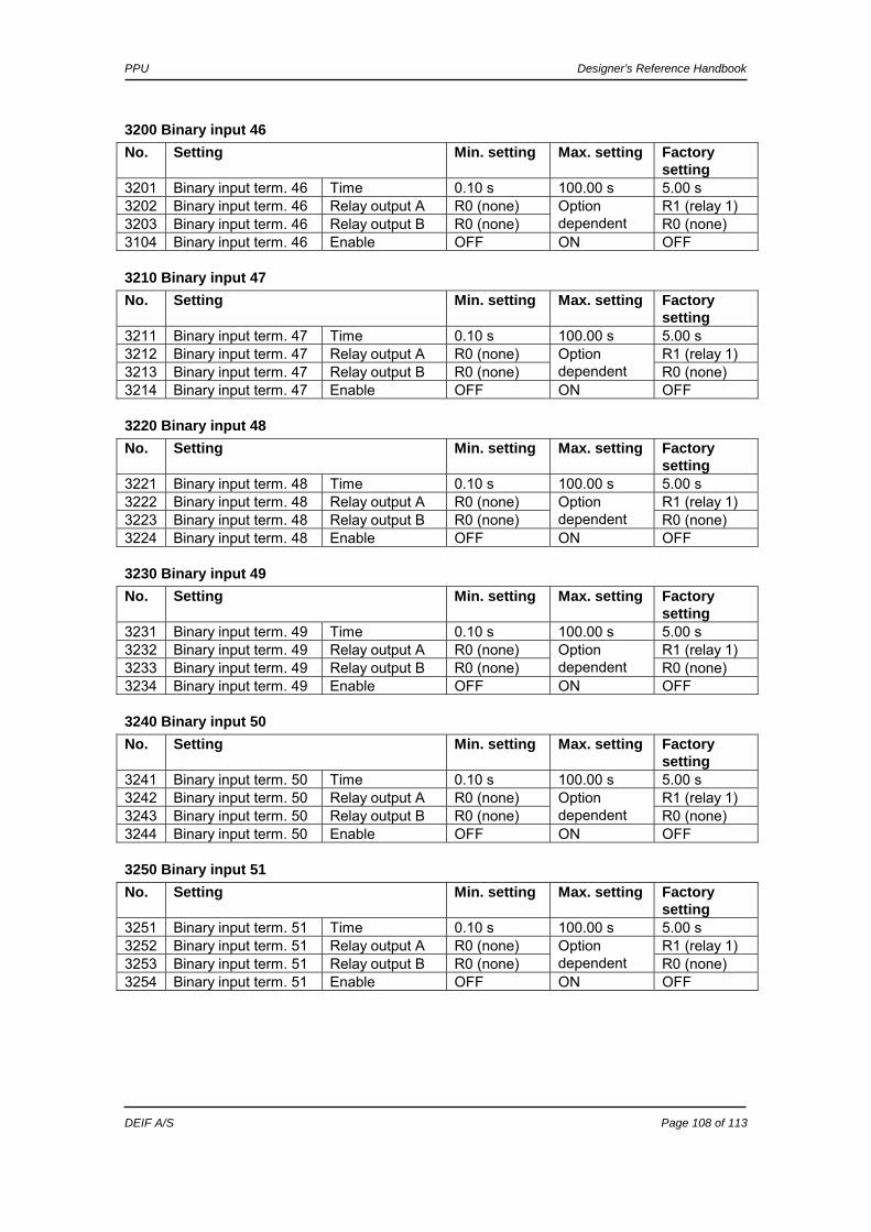
PPU Designer’s Reference Handbook
DEIF A/S Page 108 of 113
3200 Binary input 46 No. Setting Min. setting Max. setting Factory
setting 3201 Binary input term. 46 Time 0.10 s 100.00 s 5.00 s 3202 Binary input term. 46 Relay output A R0 (none) R1 (relay 1) 3203 Binary input term. 46 Relay output B R0 (none)
Option dependent R0 (none)
3104 Binary input term. 46 Enable OFF ON OFF
3210 Binary input 47 No. Setting Min. setting Max. setting Factory
setting 3211 Binary input term. 47 Time 0.10 s 100.00 s 5.00 s 3212 Binary input term. 47 Relay output A R0 (none) R1 (relay 1) 3213 Binary input term. 47 Relay output B R0 (none)
Option dependent R0 (none)
3214 Binary input term. 47 Enable OFF ON OFF
3220 Binary input 48 No. Setting Min. setting Max. setting Factory
setting 3221 Binary input term. 48 Time 0.10 s 100.00 s 5.00 s 3222 Binary input term. 48 Relay output A R0 (none) R1 (relay 1) 3223 Binary input term. 48 Relay output B R0 (none)
Option dependent R0 (none)
3224 Binary input term. 48 Enable OFF ON OFF
3230 Binary input 49 No. Setting Min. setting Max. setting Factory
setting 3231 Binary input term. 49 Time 0.10 s 100.00 s 5.00 s 3232 Binary input term. 49 Relay output A R0 (none) R1 (relay 1) 3233 Binary input term. 49 Relay output B R0 (none)
Option dependent R0 (none)
3234 Binary input term. 49 Enable OFF ON OFF
3240 Binary input 50 No. Setting Min. setting Max. setting Factory
setting 3241 Binary input term. 50 Time 0.10 s 100.00 s 5.00 s 3242 Binary input term. 50 Relay output A R0 (none) R1 (relay 1) 3243 Binary input term. 50 Relay output B R0 (none)
Option dependent R0 (none)
3244 Binary input term. 50 Enable OFF ON OFF
3250 Binary input 51 No. Setting Min. setting Max. setting Factory
setting 3251 Binary input term. 51 Time 0.10 s 100.00 s 5.00 s 3252 Binary input term. 51 Relay output A R0 (none) R1 (relay 1) 3253 Binary input term. 51 Relay output B R0 (none)
Option dependent R0 (none)
3254 Binary input term. 51 Enable OFF ON OFF

PPU Designer’s Reference Handbook
DEIF A/S Page 109 of 113
3260 Binary input 52 No. Setting Min. setting Max. setting Factory
setting 3261 Binary input term. 52 Time 0.10 s 100.00 s 5.00 s 3262 Binary input term. 52 Relay output A R0 (none) R1 (relay 1) 3263 Binary input term. 52 Relay output B R0 (none)
Option dependent R0 (none)
3264 Binary input term. 52 Enable OFF ON OFF
3270 Binary input 53 No. Setting Min. setting Max. setting Factory
setting 3271 Binary input term. 53 Time 0.10 s 100.00 s 5.00 s 3272 Binary input term. 53 Relay output A R0 (none) R1 (relay 1) 3273 Binary input term. 53 Relay output B R0 (none)
Option dependent R0 (none)
3274 Binary input term. 53 Enable OFF ON OFF
System The menu includes parameters for the system setup.
4010 Nominal settings No. Setting Min. setting Max. setting Factory
setting 4011 Nominal settings Frequency 48.0Hz 62.0Hz 60.0Hz 4012 Nominal settings Generator power 10 kW 99 MW 480 kW 4013 Nominal settings Generator current 0 A 9000 A 787 A 4014 Nominal settings Generator volt. 100 V 25000 V 440 V
4020 Transformer gen. No. Setting Min. setting Max. setting Factory
setting 4021 Transformer gen. Volt. prim. 100 V 25000 V 440 V 4022 Transformer gen. Volt. sec. 100 V 690 V 440 V 4023 Transformer gen. Current prim. 5 A 9000 A 1000 A 4024 Transformer gen. Current sec. 1 A 5 A 5 A
4030 Transformer bus No. Setting Min. setting Max. setting Factory
setting 4031 Transformer bus. Volt. prim. 100 V 25000 V 440 V 4032 Transformer bus. Volt. sec. 100 V 690 V 440 V 4033 Transformer bus U bus nominal 100 V 25000 V 440 V
4040 Controller No. Setting Min. setting Max. setting Factory
setting 4041 Controller Power -100% 100% 100% 4042 Controller VAr -100% 250% 30% 4043 Controller Power factor (ind.) 0.60 1.00 0.90 4044 Controller Water level
regulation 0% 250% 100%
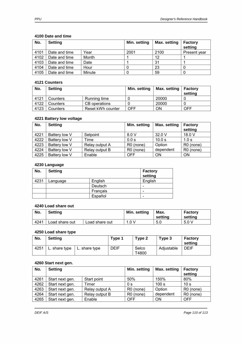
PPU Designer’s Reference Handbook
DEIF A/S Page 110 of 113
4100 Date and time No. Setting Min. setting Max. setting Factory
setting 4101 Date and time Year 2001 2100 Present year 4102 Date and time Month 1 12 1 4103 Date and time Date 1 31 1 4104 Date and time Hour 0 23 0 4105 Date and time Minute 0 59 0
4121 Counters No. Setting Min. setting Max. setting Factory
setting 4121 Counters Running time 0 20000 0 4122 Counters CB operations 0 20000 0 4123 Counters Reset kWh counter OFF ON OFF
4221 Battery low voltage No. Setting Min. setting Max. setting Factory
setting 4221 Battery low V Setpoint 8.0 V 32.0 V 18.0 V 4222 Battery low V Time 0.0 s 10.0 s 1.0 s 4223 Battery low V Relay output A R0 (none) R0 (none) 4224 Battery low V Relay output B R0 (none)
Option dependent R0 (none)
4225 Battery low V Enable OFF ON ON
4230 Language No. Setting Factory
setting 4231 Language English English Deutsch - Français - Español -
4240 Load share out No. Setting Min. setting Max.
setting Factory setting
4241 Load share out Load share out 1.0 V 5.0 5.0 V
4250 Load share type No. Setting Type 1 Type 2 Type 3 Factory
setting 4251 L. share type L. share type DEIF Selco
T4800 Adjustable DEIF
4260 Start next gen. No. Setting Min. setting Max. setting Factory
setting 4261 Start next gen. Start point 50% 150% 80% 4262 Start next gen. Timer 0 s 100 s 10 s 4263 Start next gen. Relay output A R0 (none) R0 (none) 4264 Start next gen. Relay output B R0 (none)
Option dependent R0 (none)
4265 Start next gen. Enable OFF ON OFF
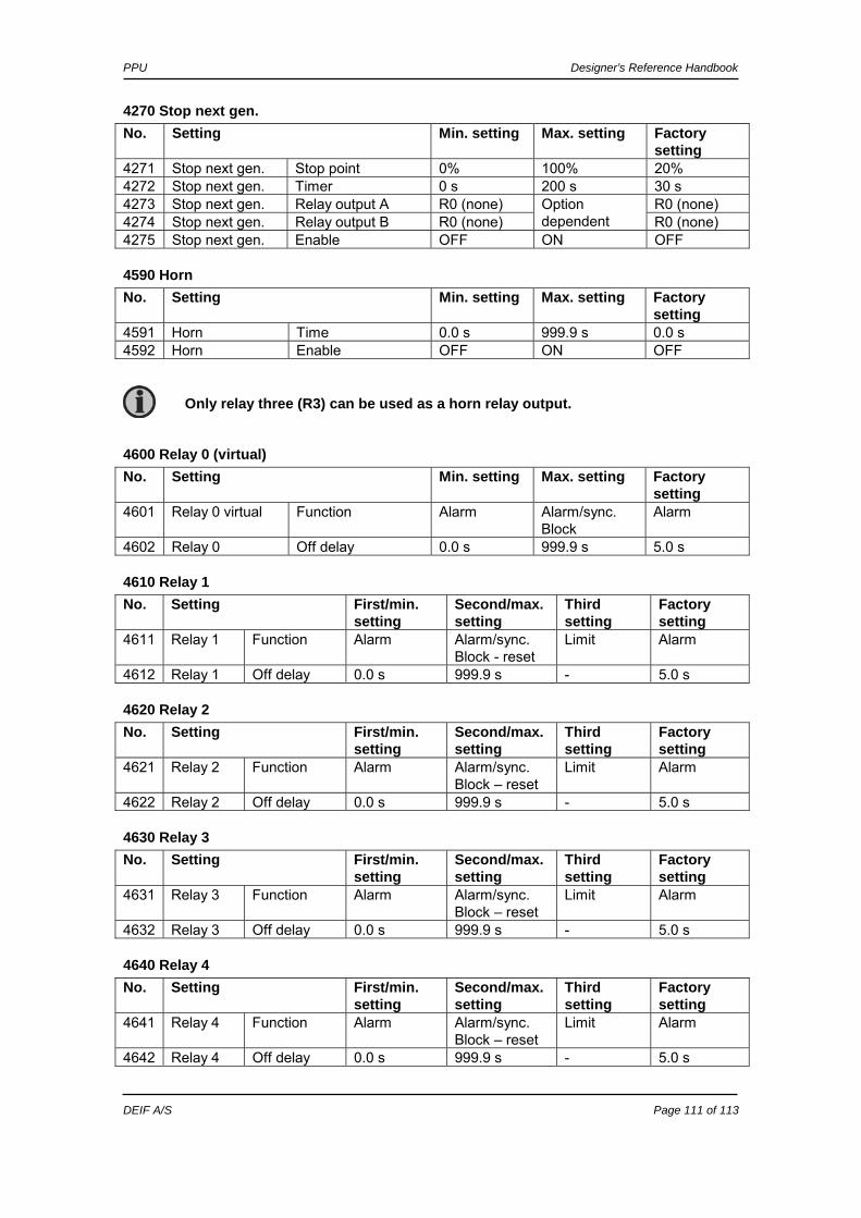
PPU Designer’s Reference Handbook
DEIF A/S Page 111 of 113
4270 Stop next gen. No. Setting Min. setting Max. setting Factory
setting 4271 Stop next gen. Stop point 0% 100% 20% 4272 Stop next gen. Timer 0 s 200 s 30 s 4273 Stop next gen. Relay output A R0 (none) R0 (none) 4274 Stop next gen. Relay output B R0 (none)
Option dependent R0 (none)
4275 Stop next gen. Enable OFF ON OFF
4590 Horn No. Setting Min. setting Max. setting Factory
setting 4591 Horn Time 0.0 s 999.9 s 0.0 s 4592 Horn Enable OFF ON OFF
4600 Relay 0 (virtual) No. Setting Min. setting Max. setting Factory
setting 4601 Relay 0 virtual Function Alarm Alarm/sync.
Block Alarm
4602 Relay 0 Off delay 0.0 s 999.9 s 5.0 s
4610 Relay 1 No. Setting First/min.
setting Second/max. setting
Third setting
Factory setting
4611 Relay 1 Function Alarm Alarm/sync. Block - reset
Limit Alarm
4612 Relay 1 Off delay 0.0 s 999.9 s - 5.0 s
4620 Relay 2 No. Setting First/min.
setting Second/max. setting
Third setting
Factory setting
4621 Relay 2 Function Alarm Alarm/sync. Block – reset
Limit Alarm
4622 Relay 2 Off delay 0.0 s 999.9 s - 5.0 s
4630 Relay 3 No. Setting First/min.
setting Second/max. setting
Third setting
Factory setting
4631 Relay 3 Function Alarm Alarm/sync. Block – reset
Limit Alarm
4632 Relay 3 Off delay 0.0 s 999.9 s - 5.0 s
4640 Relay 4 No. Setting First/min.
setting Second/max. setting
Third setting
Factory setting
4641 Relay 4 Function Alarm Alarm/sync. Block – reset
Limit Alarm
4642 Relay 4 Off delay 0.0 s 999.9 s - 5.0 s
Only relay three (R3) can be used as a horn relay output.
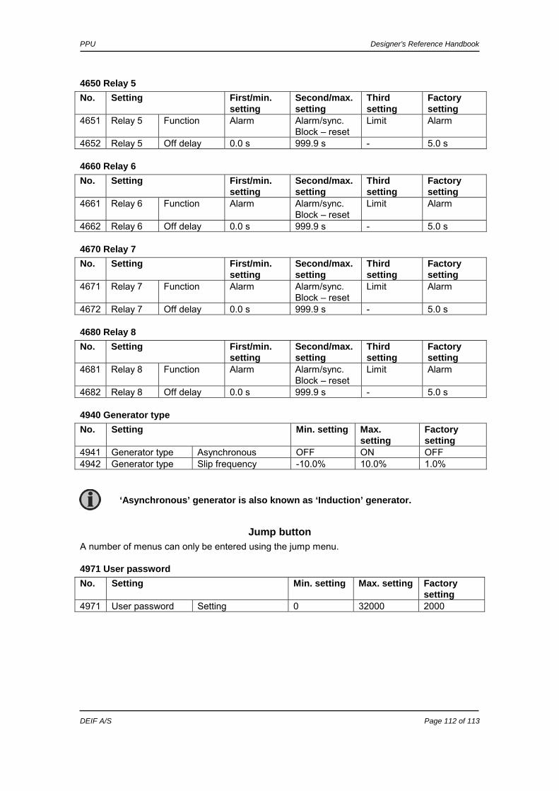
PPU Designer’s Reference Handbook
DEIF A/S Page 112 of 113
4650 Relay 5 No. Setting First/min.
setting Second/max. setting
Third setting
Factory setting
4651 Relay 5 Function Alarm Alarm/sync. Block – reset
Limit Alarm
4652 Relay 5 Off delay 0.0 s 999.9 s - 5.0 s
4660 Relay 6 No. Setting First/min.
setting Second/max. setting
Third setting
Factory setting
4661 Relay 6 Function Alarm Alarm/sync. Block – reset
Limit Alarm
4662 Relay 6 Off delay 0.0 s 999.9 s - 5.0 s
4670 Relay 7 No. Setting First/min.
setting Second/max. setting
Third setting
Factory setting
4671 Relay 7 Function Alarm Alarm/sync. Block – reset
Limit Alarm
4672 Relay 7 Off delay 0.0 s 999.9 s - 5.0 s
4680 Relay 8 No. Setting First/min.
setting Second/max. setting
Third setting
Factory setting
4681 Relay 8 Function Alarm Alarm/sync. Block – reset
Limit Alarm
4682 Relay 8 Off delay 0.0 s 999.9 s - 5.0 s
4940 Generator type No. Setting Min. setting Max.
setting Factory setting
4941 Generator type Asynchronous OFF ON OFF 4942 Generator type Slip frequency -10.0% 10.0% 1.0%
Jump button A number of menus can only be entered using the jump menu.
4971 User password No. Setting Min. setting Max. setting Factory
setting 4971 User password Setting 0 32000 2000
‘Asynchronous’ generator is also known as ‘Induction’ generator.

PPU Designer’s Reference Handbook
DEIF A/S Page 113 of 113
4972 YYYYY password No. Setting Min. setting Max. setting Factory
setting 4971 YYYYY password Setting 0 32000 4972
4980 Service menu No. Setting Description 4981 Service menu Alarm Shows remaining delay time 4982 Service menu Digital input Shows binary input status 4983 Service menu Digital output Shows relay output status
6100 Application No. Setting Description Factory setting 6100 Application Mode 0 Normal (3 phase) Normal (3 phase) 6100 Application Mode 1 Split phase - 6100 Application Mode 2 Single phase -
6200 Phase compensation No. Setting Min. setting Max. setting Factory
setting 6200 Phase
compensation Setpoint -45 deg. 45 deg. 0.0 deg.
DEIF A/S reserves the right to change any of the above.
This is the backup password. If it is changed keep the new password in a safe place.