lsa 42 - leroy- · pdf filefor paralleling mains paralleling 3-phase sensing 3-phase sensing...
TRANSCRIPT
LSA 42.3
Low Voltage Alternators - 4 pole25 to 60 kVA - 50 Hz / 31.5 to 75 kVA - 60 Hz
Electrical and mechanical data

2 Electric Power Generation
LSA 42.3 - 25 to 60 kVA - 50 Hz / 31.5 to 75 kVA - 60 Hz
Specially adapted to applicationsThe LSA 42.3 alternator is designed to be suitable for typical generator applications, such as: backup, marine applications, rental, telecommunications, etc.
Compliant with international standardsThe LSA 42.3 alternator conforms to the main international standards and regulations: - IEC 60034, NEMA MG 1.32-33, ISO 8528-3, CSA C22.2 n°100-14, UL 1446 (UL 1004 on request), marine regulations, etc.It can be integrated into a CE marked generator.The LSA 42.3 is designed, manufactured and marketed in an ISO 9001 and ISO 14001 environment.
Top of the range electrical performance ● Class H insulation. ● Standard 12 wire re-connectable winding, 2/3 pitch, type no. 6 ● Voltage range: - 50 Hz: 220 V - 240 V and 380 V - 415 V (440 V) - 60 Hz: 208 V - 240 V and 380 V - 480 V ● High efficiency and motor starting capacity ● Other voltages are possible with optional adapted windings: - 50 Hz: 440 V (no. 7), 500 V (no. 9), 690 V (n°10) - 60 Hz: 380 V and 416 V (no. 8), 600 V (no. 9) ● R 791 interference suppression conforming to standard EN 61000-6-3, EN 61000-6-2, EN 55011 group 1 class B standard for
European zone (CE marking)
Reinforced mechanical structure using finite element modelling ● Compact rigid assembly to better withstand generator vibrations ● Steel frame ● Aluminium flanges and shields ● Two-bearing and single-bearing versions designed to be suitable for commercially-available heat engines ● Half-key balancing two bearing ● Permanently greased bearings (20 000h) ● Direction of rotation : clockwise and anti-clockwise (without derating)
Excitation and regulation system suited to the applicationExcitation system Regulation options
Voltage regulator SHUNT AREP PMG
Current transformer
for parallelingMains
paralleling3-phasesensing
3-phase sensing formains paralleling
unbalancedRemote voltagepotentiometer
R220 Std - - - - - - -R438 - Std Std C.T. R726* R731* R734* √R450* Option Option Option C.T. R726* R731* R734* √
D510C* Option Option Option C.T. included included contacter factory √ * Steel terminal box mounting only √: Possible mounting
Compact and design terminal box ● Easy access to the AVR (lid) and to the connections ● 8 way terminal block for reconnecting the voltage ● Predrilled holes for cable gland ● Steel terminal box in option
Protection system suited to the environment ● The LSA 42.3 is IP 23 ● Standard winding protection for clean environments with relative humidity ≤ 95%, including indoor marine environments ● Options: - Filters on air inlet : derating 5% - Filters on air inlet and air outlet (IP 44) : derating 10% - Winding protection for harsh environments and relative humidity greater than 95% - Space heaters - Thermal protection for stator windings - Height fixing : H = 225 mm (option) with the order

3Electric Power Generation
Phase 3 ph. 1 ph. 3 ph. 1 ph. 3 ph. 1 ph. 3 ph. 1 ph.Y 380V 400V 415V 440V ∆∆ 380V 400V 415V 440V ∆∆ 380V 400V 415V 440V ∆∆ 380V 400V 415V 440V ∆∆∆ 220V 230V 240V 230V 220V 230V 240V 230V 220V 230V 240V 230V 220V 230V 240V 230V
YY 220V 220V 220V 220V
42.3 VS1 kVA 25 24.5 15 22.8 22.3 13.7 26.5 26 15.9 27.5 27 16.5kW 20 19.6 12 18.2 17.9 10.9 21.2 20.8 12.7 22 21.6 13.2
42.3 VS2 kVA 27 26 16.2 24.6 23.6 14.7 28.9 27.6 17.3 30 28 18kW 21.6 20.8 13 19.7 18.9 11.8 23.1 22.1 13.9 24 22.9 14.4
42.3 VS3 kVA 32 30 19.2 29.1 27.3 17.5 34 31.8 20.4 35.2 33.0 21.1kW 25.6 24 15.4 23.3 21.8 14 27.1 25.4 16.3 28.2 26.4 16.9
42.3 S4 kVA 35 30.6 22 32 27.9 20 37.1 32.5 23.3 38.5 33.7 24.2kW 28 24.5 17.6 25.5 22.3 16 29.7 26 18.7 30.8 27.0 19.4
42.3 S5 kVA 40 35 25 36.4 31.9 22.8 42.4 37.1 26.5 45 38.5 28.1kW 32 28 20 29.1 25.5 18.2 33.9 29.7 21.2 36 30.8 22.5
42.3 M7 kVA 45 39 27 41 35.5 24.6 48.2 41.3 28.9 50 42.9 30kW 36 31.2 21.6 32.8 28.4 19.7 38.5 33.1 23.1 40 34.3 24
42.3 M8 kVA 50 43 30 45.5 39.1 27.3 53 45.6 31.8 55 47.3 33kW 40 34.4 24 36.4 31.3 21.8 42.4 36.5 25.4 44 37.8 26.4
42.3 L9 kVA 60 51.6 36 54.6 47.0 32.8 63.6 54.7 38.2 66 56.8 40kW 48 41.3 28.8 43.7 37.6 26.2 50.9 43.8 30.5 52.8 45.4 32
Phase 3 ph. 1 ph. 3 ph. 1 ph. 3 ph. 1 ph. 3 ph. 1 ph.Y 380V 416V 440V 480V ∆∆ 380V 416V 440V 480V ∆∆ 380V 416V 440V 480V ∆∆ 380V 416V 440V 480V ∆∆∆ 220V 240V 240V 220V 240V 240V 220V 240V 240V 220V 240V 240V
YY 208V 220V 240V 208V 220V 240V 208V 220V 240V 208V 220V 240V
42.3 VS1 kVA 29.1 31.3 31.5 31.5 18.9 26.5 28.4 28.7 28.7 17,2 30.8 33.1 33.4 33.4 19,8 32 34.4 34.7 34.7 20,8 kW 23.3 25 25.2 25.2 15.1 21.2 22.8 22.9 22.9 13,7 24.7 26.5 26.7 26.7 15,9 25.6 27.5 27.7 27.7 16,6
42.3 VS2 kVA 29.9 31.9 33.8 33.8 19.2 26.9 29 30.7 30.7 17,5 31.4 33.8 35.8 35.8 20,2 32.5 35.1 37.5 37.5 21,1 kW 23.7 25.5 27 27 15.4 21.5 23.2 24.6 24.6 14,0 25.1 27.1 28.6 28.6 16,2 26 28.1 30 30 16,9
42.3 VS3 kVA 34.5 38 40 40 22.8 31.4 34.6 36.4 36.4 20,7 36.6 40.3 42.4 42.4 23,9 38 41.8 44 44 25,1 kW 27.6 30.4 32 32 18.2 25.1 27.7 29.1 29.1 16,6 29.3 32.2 33.9 33.9 19,1 30.4 33.4 35.2 35.2 20,0
42.3 S4 kVA 37.5 40.3 42.9 43.8 24.2 33.4 36.6 39.0 39.8 22,0 39 42.7 45.4 46.4 25,4 40.4 44.3 47.2 48.1 26,6 kW 30 32.2 34.3 35 19.3 26.8 29.3 31.2 31.9 17,6 31.2 34.1 36.4 37.1 20,3 32.3 35.4 37.7 38.5 21,2
42.3 S5 kVA 42 46 49 50 27.6 38.2 41.9 44.6 45.5 25,1 44.5 50 51.9 53 29,0 46.2 50.6 53.9 55 30,4 kW 33.6 36.8 39.2 40 22.1 30.6 33.5 35.7 36.4 20,1 35.6 40 41.6 42.4 23,2 37 40.5 43.1 44 24,3
42.3 M7 kVA 46 50 53.5 56.5 30 41.9 45.5 48.7 51.4 27,3 48.8 53 56.7 59.9 31,5 50.6 55 58.9 62.5 33,0 kW 36.8 40 42.8 45.2 24 33.5 36.4 38.9 41.1 21,8 39 42.4 45.4 47.9 25,2 40.5 44 47.1 50 26,4
42.3 M8 kVA 51.5 56.5 59.5 62.5 33.9 46.9 51.4 54.1 57 30,8 54.6 60 63.1 66.3 35,6 56.7 62.5 65.5 68.8 37,3 kW 41.2 45.2 47.6 50 27.1 37.5 41.1 43.3 45.5 24,7 43.7 48 50.5 53 28,5 45.3 50 52.4 55 29,8
42.3 L9 kVA 59 65 69 75 39 53.7 59.2 62.8 68.3 35,5 62.5 68.9 73.1 79.5 41,0 64.9 71.5 75.9 82.5 42,9 kW 47.2 52.0 55.2 60 31.2 43.0 47.3 50.2 54.6 28,4 50.0 55.1 58.5 63.6 32,8 51.9 57.2 60.7 66.0 34,3
LSA 42.3 - 25 to 60 kVA - 50 Hz / 31.5 to 75 kVA - 60 Hz
General characteristics
kVA / kW - P.F. = 0.8Duty/T°C Continuous duty/40°C Continuous duty/40°C Stand-by/40°C Stand-by/27°CClass/T°K H/125°K F/105°K H/150°K H/163°K
Insulation class H Excitation system SHUNT AREP or PMGWinding pitch 2/3 (wdg 6) AVR type R 220 R 438Number of wires 12 Voltage regulation (*) ± 0.5 % ± 0.5 %Protection IP 23 Short-circuit current - 300% (3 IN): 10 sAltitude ≤ 1000 m Total Harmonic Distortion THD (**) in no-load ..... : < 2%Overspeed 2250 min-1 Total Harmonic Distortion THD (**) on linear load : < 4%Air flow 0.10m3/s, 50 Hz - 0.13m3/s, 60 Hz Waveform: NEMA = TIF (**) < 50(*) Steady state. (**) Total harmonic distortion between phases, no-load or on-load (non-distorting).
kVA / kW - P.F. = 0.8Duty/T°C Continuous duty/40°C Continuous duty/40°C Stand-by/40°C Stand-by/27°CClass/T°K H/125°K F/105°K H/150°K H/163°K
Ratings 60 Hz - 1800 R.P.M.
Ratings 50 Hz - 1500 R.P.M.
4 Electric Power Generation
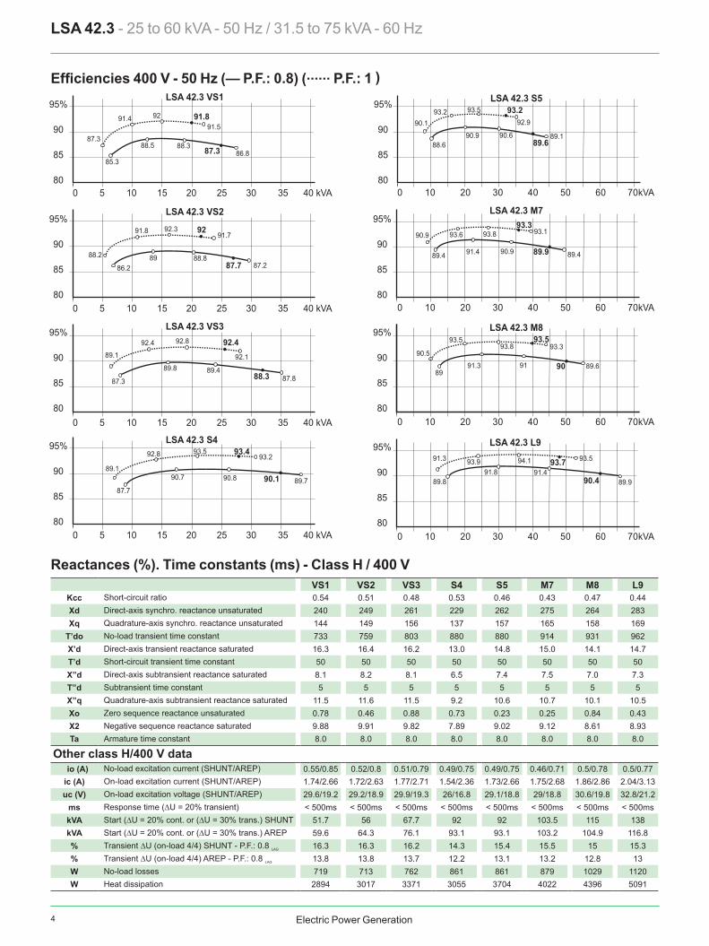
VS1 VS2 VS3 S4 S5 M7 M8 L9Kcc 0.54 0.51 0.48 0.53 0.46 0.43 0.47 0.44Xd 240 249 261 229 262 275 264 283Xq 144 149 156 137 157 165 158 169
T’do 733 759 803 880 880 914 931 962X’d 16.3 16.4 16.2 13.0 14.8 15.0 14.1 14.7T’d 50 50 50 50 50 50 50 50X”d 8.1 8.2 8.1 6.5 7.4 7.5 7.0 7.3T”d 5 5 5 5 5 5 5 5X”q 11.5 11.6 11.5 9.2 10.6 10.7 10.1 10.5Xo 0.78 0.46 0.88 0.73 0.23 0.25 0.84 0.43X2 9.88 9.91 9.82 7.89 9.02 9.12 8.61 8.93Ta 8.0 8.0 8.0 8.0 8.0 8.0 8.0 8.0
io (A) 0.55/0.85 0.52/0.8 0.51/0.79 0.49/0.75 0.49/0.75 0.46/0.71 0.5/0.78 0.5/0.77ic (A) 1.74/2.66 1.72/2.63 1.77/2.71 1.54/2.36 1.73/2.66 1.75/2.68 1.86/2.86 2.04/3.13uc (V) 29.6/19.2 29.2/18.9 29.9/19.3 26/16.8 29.1/18.8 29/18.8 30.6/19.8 32.8/21.2
ms < 500ms < 500ms < 500ms < 500ms < 500ms < 500ms < 500ms < 500mskVA 51.7 56 67.7 92 92 103.5 115 138kVA 59.6 64.3 76.1 93.1 93.1 103.2 104.9 116.8% 16.3 16.3 16.2 14.3 15.4 15.5 15 15.3% 13.8 13.8 13.7 12.2 13.1 13.2 12.8 13W 719 713 762 861 861 879 1029 1120W 2894 3017 3371 3055 3704 4022 4396 5091
95%
90
85
800 5 10 15 20 25 30 35 40 kVA
0 5 10 15 20 25 30 35 40 kVA
0 5 10 15 20 25 30 35 40 kVA
0 5 10 15 20 25 30 35 40 kVA
LSA 42.3 VS1
87.388.3
86.8
91.5
85.3
88.5
91.4 92 91.8
87.3
95%
90
85
80
LSA 42.3 VS2
92
87.288.2 89 88.8
91.8 92.3
86.2
91.7
87.7
95%
90
85
80
LSA 42.3 VS3
95%
90
85
80
LSA 42.3 S4
90.1
92.8
89.787.7
89.190.7
93.5
90.8
93.293.4
95%
90
85
80
LSA 42.3 M7
89.4
90.993.3
90.9
93.1
91.4
93.6 93.8
89.489.9
95%
90
85
80
LSA 42.3 M8
LSA 42.3 L9
89
90.5
9091 89.691.3
93.593.8 93.3
93.5
0 10 20 30 40 50 60 70kVA
0 10 20 30 40 50 60 70kVA
0 10 20 30 40 50 60 70kVA
0 10 20 30 40 50 60 70kVA
95%
90
85
80
89.8
91.3
90.491.4
89.9
93.5
91.893.9 93.794.1
89.1
89.487.8
92.1
87.3
89.8
92.4 92.8 92.4
88.3
95%
90
85
80
LSA 42.3 S5
89.6
93.2
89.188.6
90.1
90.9
93.5
90.6
92.993.2
LSA 42.3 - 25 to 60 kVA - 50 Hz / 31.5 to 75 kVA - 60 Hz
Efficiencies 400 V - 50 Hz (— P.F.: 0.8) (...... P.F.: 1 )
Short-circuit ratioDirect-axis synchro. reactance unsaturatedQuadrature-axis synchro. reactance unsaturatedNo-load transient time constantDirect-axis transient reactance saturatedShort-circuit transient time constantDirect-axis subtransient reactance saturatedSubtransient time constantQuadrature-axis subtransient reactance saturatedZero sequence reactance unsaturatedNegative sequence reactance saturatedArmature time constant
Other class H/400 V dataNo-load excitation current (SHUNT/AREP)On-load excitation current (SHUNT/AREP)On-load excitation voltage (SHUNT/AREP)Response time (∆U = 20% transient)Start (∆U = 20% cont. or (∆U = 30% trans.) SHUNTStart (∆U = 20% cont. or (∆U = 30% trans.) AREPTransient ∆U (on-load 4/4) SHUNT - P.F.: 0.8 LAG
Transient ∆U (on-load 4/4) AREP - P.F.: 0.8 LAG
No-load lossesHeat dissipation
Reactances (%). Time constants (ms) - Class H / 400 V

5Electric Power Generation
LSA 42.3 - 25 to 60 kVA - 50 Hz / 31.5 to 75 kVA - 60 Hz
Transient voltage variation 400V - 50 Hz
1) For a starting P.F. other than 0.6, the starting kVA must be multiplied by K = Sine P.F. / 0.8Calculation example for a different P.F. other than 0.6: Starter motor kVA calculated at 0.4 P.F. = 40 kVA> Sin P.F. 0.4 = 0.9165 > K = 1.145 > kVA corrected = 45.8 kVA > Voltage dip corresponding to L9 = 13%.
2) For voltages other than 400V (Y), 230V (∆) at 50 Hz, then kVA must be multiplied by (400/U)2 or (230/U)2.
Phase loading (SHUNT)
kVA at PF Ø 0.8
kVA at PF Ø 0.8
Volta
ge d
rop
Load shedding (SHUNT)
Volta
ge ri
seVo
ltage
dro
p
Motor starting (SHUNT)
locked rotor kVA at PF Ø 0.6
Phase loading (AREP & PMG)
kVA at PF Ø 0.8
kVA at PFØ 0.8
Volta
ge d
rop
Load shedding (AREP & PMG)
Volta
ge ri
seVo
ltage
dro
p
Motor starting (AREP & PMG)
locked rotor kVA at PF Ø 0.6
0 40 80 120 kVA
30 %
25
20
15
10
5
40%
30
20
10
40%
30
20
10
VS1 VS2 VS3 S4 S5
M7
VS1 VS2 VS3 S4 S5 M7 M8 L9
VS1 VS2 VS3 S4 S5 M7M8
L9
M8
L9
0 40 80 120 160 200kVA
13%
45.8
0 40 80 120 kVA
0 40 80 120 kVA
30 %
25
20
15
10
5
40%
30
20
10
40%
30
20
10
VS1 VS2 VS3 S4S5
M7
VS1 VS2 VS3 S4 S5 M7
M8
L9
VS1 VS2 VS3 S4 S5
M7
M8
L9
M8
L9
0 40 80 120 160 200kVA
0 40 80 120 kVA

6 Electric Power Generation
VS1 VS2 VS3 S4 S5 M7 M8 L9Kcc 0.52 0.49 0.46 0.51 0.44 0.41 0.45 0.42Xd 252 260 272 239 273 287 275 294Xq 151 156 163 143 163 172 165 176
T’do 733 759 803 880 880 914 931 962X’d 17.2 17.1 16.9 13.5 15.5 15.7 14.7 15.3T’d 50 50 50 50 50 50 50 50X”d 8.6 8.5 8.4 6.7 7.7 7.8 7.3 7.6T”d 5 5 5 5 5 5 5 5X”q 12.1 12.1 12.0 9.6 11.0 11.2 10.5 10.5Xo 0.46 0.83 0.31 0.26 0.69 0.05 0.97 0.86X2 10.37 10.35 10.24 8.22 9.39 9.55 8.97 9.30Ta 8.0 8.0 8.0 8.0 8.0 8.0 8.0 8.0
io (A) 0.55/0.85 0.52/0.8 0.51/0.79 0.49/0.75 0.49/0.75 0.46/0.71 0.5/0.77 0.5/0.77ic (A) 1.76/2.69 1.73/2.65 1.77/2.72 1.54/2.36 1.73/2.66 1.75/2.68 1.84/2.82 1.99/3.06uc (V) 30.2/19.3 29.7/19 30.3/19.4 26.4/16.9 29.4/18.8 29.5/18.8 30.9/19.7 32.9/21.1
ms < 500ms < 500ms < 500ms < 500ms < 500ms < 500ms < 500ms < 500mskVA 63.3 68.1 82 111.8 111.8 124.7 146.9 165.6kVA 71.4 76.9 92.6 121.8 121.6 133.8 137.9 152.2% 16.8 16.8 16.6 14.7 15.8 15.9 15.4 15.7% 14.1 14.1 14.0 12.5 13.4 13.5 13.0 13.3W 1021 1016 1087 1229 1229 1258 1462 1591W 3389 3505 3914 3597 4312 4709 5120 5917
95%
90
85
800 5 10 15 20 25 30 35 40 45 50kVA
0 5 10 15 20 25 30 35 40 45 50kVA
0 5 10 15 20 25 30 35 40 45 50kVA
0 5 10 15 20 25 30 35 40 45 50kVA
LSA 42.3 VS1
86.388.8 87.7
91.8
84.7
88.6
9192 92
88.1
95%
90
85
80
LSA 42.3 VS2
92.2
8887.2 89.1 89.3
91.5 92.3
85.6
92
88.5
95%
90
85
80
LSA 42.3 VS3
95%
90
85
80
LSA 42.3 S4
90.6
92.4
90.4
86.9
88.1 90.6
93.4
91.1
93.493.5
95%
90
85
80
LSA 42.3 M7
88.8
90.1
93.6
91.3
93.4
91.4
93.3 93.8
90.190.5
95%
90
85
80
LSA 42.3 M8
LSA 42.3 L9
8990.5 90
91 89.691.3
93.5 93.8
93.393.5
0 10 20 30 40 50 60 70 80 90kVA
95%
90
85
80
89.3
90.5
9191.7
90.6
93.891.8
93.693.994.1
88.289.9
88.6
92.5
86.7
89.9
92.1 92.8 92.6
89.1
0 10 20 30 40 50 60 70 80 90kVA
0 10 20 30 40 50 60 70 80 90kVA
0 10 20 30 40 50 60 70 80 90kVA
95%
90
85
80
LSA 42.3 S5
90.2
92.9
89.887.9
89.2 90.9
93.5
90.9
92.993.3
LSA 42.3 - 25 to 60 kVA - 50 Hz / 31.5 to 75 kVA - 60 Hz
Efficiencies 480 V - 60 Hz (— P.F.: 0.8) (...... P.F.: 1 )
Short-circuit ratioDirect-axis synchro. reactance unsaturatedQuadrature-axis synchro. reactance unsaturatedNo-load transient time constantDirect-axis transient reactance saturatedShort-circuit transient time constantDirect-axis subtransient reactance saturatedSubtransient time constantQuadrature-axis subtransient reactance saturatedZero sequence reactance unsaturatedNegative sequence reactance saturatedArmature time constant
Other class H/480 V dataNo-load excitation current (SHUNT/AREP)On-load excitation current (SHUNT/AREP)On-load excitation voltage (SHUNT/AREP)Response time (∆U = 20% transient)Start (∆U = 20% cont. or (∆U = 30% trans.) SHUNTStart (∆U = 20% cont. or (∆U = 30% trans.) AREPTransient ∆U (on-load 4/4) SHUNT - P.F.: 0.8 LAG
Transient ∆U (on-load 4/4) AREP - P.F.: 0.8 LAG
No-load lossesHeat dissipation
Reactances (%). Time constants (ms) - Class H / 480 V
7Electric Power Generation
LSA 42.3 - 25 to 60 kVA - 50 Hz / 31.5 to 75 kVA - 60 Hz
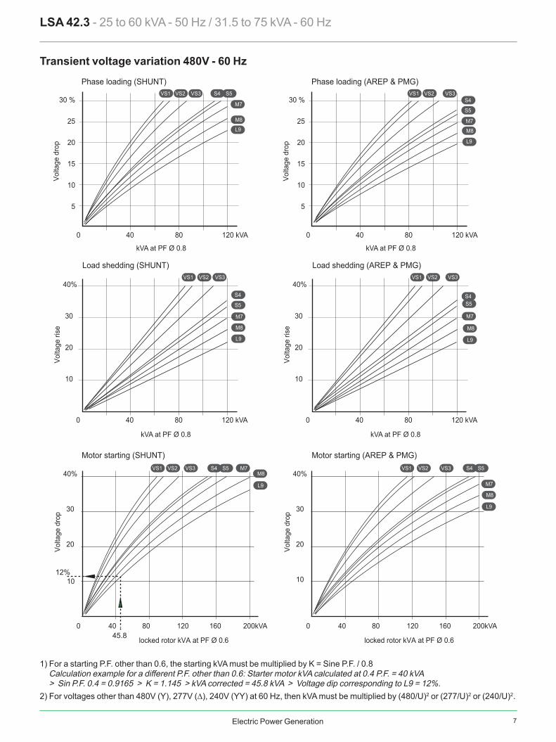
Transient voltage variation 480V - 60 Hz
1) For a starting P.F. other than 0.6, the starting kVA must be multiplied by K = Sine P.F. / 0.8Calculation example for a different P.F. other than 0.6: Starter motor kVA calculated at 0.4 P.F. = 40 kVA> Sin P.F. 0.4 = 0.9165 > K = 1.145 > kVA corrected = 45.8 kVA > Voltage dip corresponding to L9 = 12%.
2) For voltages other than 480V (Y), 277V (∆), 240V (YY) at 60 Hz, then kVA must be multiplied by (480/U)2 or (277/U)2 or (240/U)2.
0 40 80 120 kVA
30 %
25
20
15
10
5
40%
30
20
10
40%
30
20
10
VS1 VS2 VS3
S4
S5
M7
VS1 VS2 VS3 S4 S5 M7M8
L9
VS1 VS2 VS3 S4 S5
M7
M8
L9
M8
L9
0 40 80 120 160 200kVA
12%
45.8
0 40 80 120 kVA
0 40 80 120 kVA
30 %
25
20
15
10
5
40%
30
20
10
40%
30
20
10
VS1 VS2 VS3
S4S5
M7
VS1 VS2 VS3 S4 S5
M7
M8
L9
VS1 VS2 VS3S4
S5
M7
M8
L9
M8
L9
0 40 80 120 160 200kVA
0 40 80 120 kVA
Phase loading (SHUNT)
kVA at PF Ø 0.8
kVA at PF Ø 0.8
Volta
ge d
rop
Load shedding (SHUNT)
Volta
ge ri
seVo
ltage
dro
p
Motor starting (SHUNT)
locked rotor kVA at PF Ø 0.6
Phase loading (AREP & PMG)
kVA at PF Ø 0.8
kVA at PF Ø 0.8
Volta
ge d
rop
Load shedding (AREP & PMG)
Volta
ge ri
seVo
ltage
dro
p
Motor starting (AREP & PMG)
locked rotor kVA at PF Ø 0.6

8 Electric Power Generation
LSA 42.3 - 25 to 60 kVA - 50 Hz / 31.5 to 75 kVA - 60 Hz
3-phase short-circuit curves at no load and rated speed (star connection Y)
Influence due to connectionCurves shown are for star (Y) connection.For other connections, use the following multiplication factors: - Series delta : current value x 1.732 - Parallel star : current value x 2
LSA 423 VS1
LSA 423 VS3
1 10 100 1000 10000
1 10 100 1000 10000
SHUNT
LSA 423 VS2
1 10 100 1000 10000
10000
1000
100
10
10000
1000
100
10
10000
1000
100
10
10000
1000
100
10
AREP
SHUNT
AREP
SHUNT
AREP
SHUNT
AREP
LSA 423 S4
1 10 100 1000 10000
Cur
rent
(A)
Cur
rent
(A)
Cur
rent
(A)
Cur
rent
(A)
time (ms)
time (ms)
time (ms)
time (ms)
SymmetricalAsymmetrical
SymmetricalAsymmetrical
SymmetricalAsymmetrical
SymmetricalAsymmetrical
9Electric Power Generation
LSA 42.3 - 25 to 60 kVA - 50 Hz / 31.5 to 75 kVA - 60 Hz
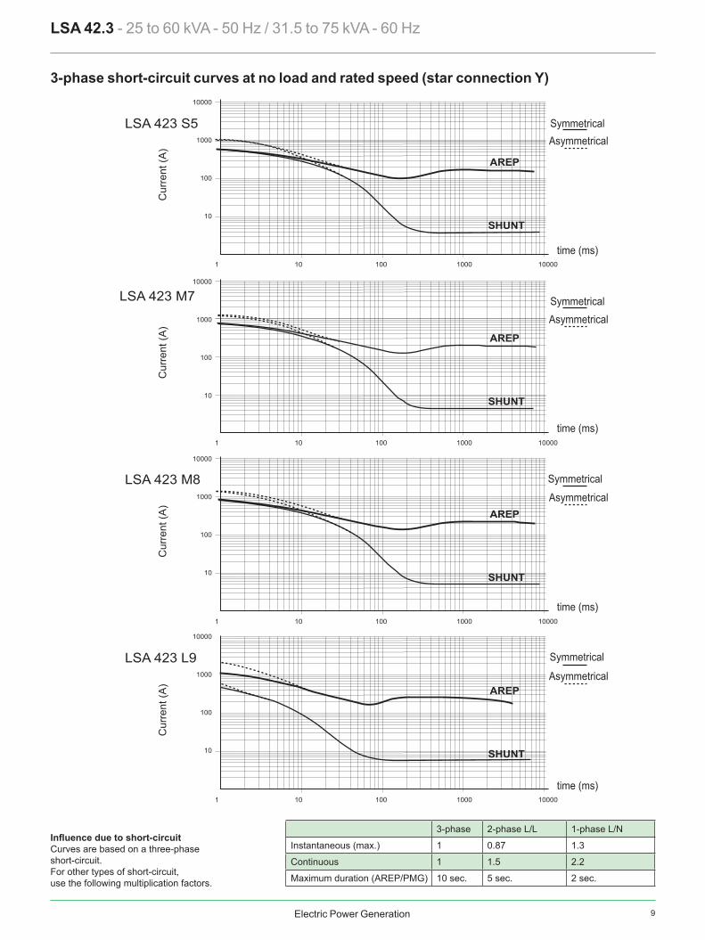
3-phase short-circuit curves at no load and rated speed (star connection Y)
Influence due to short-circuitCurves are based on a three-phaseshort-circuit.For other types of short-circuit, use the following multiplication factors.
3-phase 2-phase L/L 1-phase L/N
Instantaneous (max.) 1 0.87 1.3
Continuous 1 1.5 2.2
Maximum duration (AREP/PMG) 10 sec. 5 sec. 2 sec.
LSA 423 M8
LSA 423 M7
00001 0001 001 01 1
00001 0001 001 01 1
LSA 423 L9
00001 0001 001 01 1
LSA 423 S5
00001 0001 001 01 1
SHUNT
AREP
SHUNT
AREP
SHUNT
AREP
SHUNT
AREP
10000
1000
100
10
10000
1000
100
10
10000
1000
100
10
10000
1000
100
10
Cur
rent
(A)
time (ms)
SymmetricalAsymmetrical
Cur
rent
(A)
time (ms)
SymmetricalAsymmetrical
Cur
rent
(A)
time (ms)
Symmetrical
Asymmetrical
Cur
rent
(A)
time (ms)
Symmetrical
Asymmetrical
10 Electric Power Generation
Ø 6
0
Ø 4
1
Ø 3
0
Ø 1
8
Lr
Xr
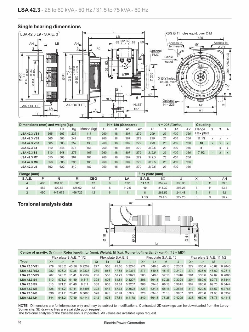
Xr Lr M J Xr Lr M J Xr Lr M J Xr Lr M J LSA 42.3 VS1 279 526.2 45.36 0.2209 277 558 45.68 0.2246 274 549.8 46.13 0.2363 272 535.6 46.62 0.2843LSA 42.3 VS2 282 526.2 47.36 0.2337 280 558 47.68 0.2374 277 549.8 48.13 0.2491 274 535.6 48.62 0.2611LSA 42.3 VS3 287 526.2 51.41 0.2592 286 558 51.73 0.2629 283 549.8 52.18 0.2746 281 535.6 52.67 0.2866LSA 42.3 S4 310 571.2 61.49 0.317 308 603 61.81 0.3207 306 594.8 62.26 0.3324 304 580.6 62.75 0.3444LSA 42.3 S5 310 571.2 61.49 0.317 308 603 61.81 0.3207 306 594.8 68.18 0.3645 304 580.6 62.75 0.3444LSA 42.3 M7 325 611.2 67.41 0.3491 323 643 67.73 0.3528 321 634.8 68.18 0.3645 319 620.6 68.67 0.3765LSA 42.3 M8 330 611.2 70.42 0.3683 328 643 70.74 0.372 326 634.8 71.18 0.3837 324 620.6 71.68 0.3957LSA 42.3 L9 344 641.2 77.49 0.4141 342 673 77.81 0.4178 340 664.8 78.25 0.4295 338 650.6 78.75 0.4415
H = 180 (Standard) H = 225 (Option)L LB Xg C B A1 A2 C B A1 A2 2 3 4
LSA 42.3 VS1 565 503 237 117 260 18 307 279 299 23 400 356LSA 42.3 VS2 565 503 242 122 260 18 307 279 299 23 400 356 11 1/2 x x -LSA 42.3 VS3 565 503 252 133 260 18 307 279 299 23 400 356 10 x x xLSA 42.3 S4 610 548 275 165 260 18 307 279 312.5 23 400 356 8 - x xLSA 42.3 S5 610 548 275 165 260 18 307 279 312.5 23 400 356 7 1/2 - x xLSA 42.3 M7 650 588 287 181 260 18 307 279 312.5 23 400 356LSA 42.3 M8 650 588 295 186 260 18 307 279 312.5 23 400 356LSA 42.3 L9 662 622 310 187 260 18 307 279 312.5 23 400 356
S.A.E. P N M XBG T LA S.A.E. BX U X Y AH4 406 361.95 381 12 6 122 11 1/2 352.42 333.38 8 11 39.63 452 409.58 428.62 12 5 112.5 10 314.32 295.28 8 11 53.82 490 447.675 466.725 12 6 111 8 263.52 244.48 6 11 62
7 1/2 241.3 222.25 8 9 30.2
LSA 42.3 - 25 to 60 kVA - 50 Hz / 31.5 to 75 kVA - 60 Hz
Single bearing dimensions
Torsional analysis data
Centre of gravity: Xr (mm), Rotor length: Lr (mm), Weight: M (kg), Moment of inertia: J (kgm2): (4J = MD2)Flex plate S.A.E. 7 1/2 Flex plate S.A.E. 8 Flex plate S.A.E. 10 Flex plate S.A.E. 11 1/2
Type
Dimensions (mm) and weight (kg)
Flange (mm) Flex plate (mm)
CouplingMasse (kg) Flange
Flex plate
Ø B
X
Ø NØ P
AH3
- 0.0
50- 0
.100
+ 0
- 0.1
27
B
78.5
15°
Ø 64
103
5214
L
LB
LA LA
Xg
598989 3232
137
420
264
(270
.5:L
9)
5
+1 -3
CT T
H
A2A1
97
Ø 2
35
L
LB3
Ø B
X
Ø NØ
455
AH
- 0.0
50- 0
.100
+ 0
- 0.1
27
C
LSA 42.3 L9 - S.A.E. 3
X Ø Y holesequid. over
Ø U
INLET
Access to Access toterminals AVR
XBG Ø 11 holes equid. over Ø M
outlet
OptionalH = 225AIR OUTLET AIR OUTLET
OptionalPMG
Cable
NOTE : Dimensions are for information only and may be subject to modifications. Contractual 2D drawings can be downloaded from the Leroy-Somer site, 3D drawing files are available upon request.The torsional analysis of the transmission is imperative. All values are available upon request.
11Electric Power Generation
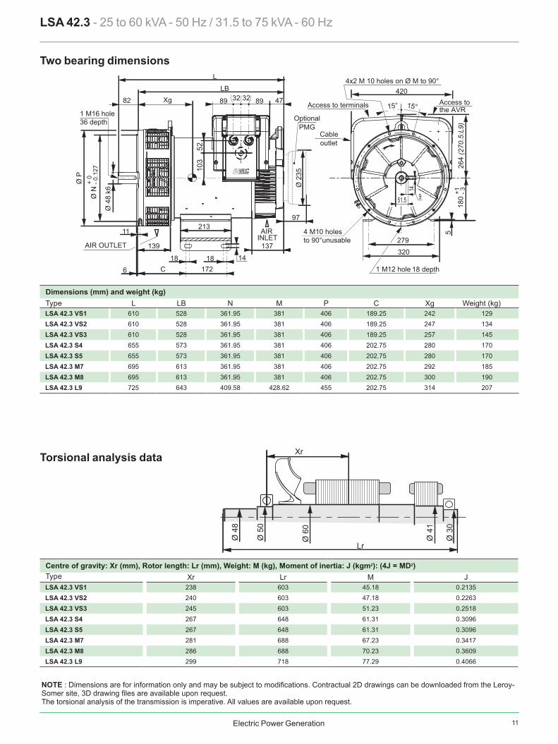
L LB N M P C XgLSA 42.3 VS1 610 528 361.95 381 406 189.25 242 129LSA 42.3 VS2 610 528 361.95 381 406 189.25 247 134LSA 42.3 VS3 610 528 361.95 381 406 189.25 257 145LSA 42.3 S4 655 573 361.95 381 406 202.75 280 170LSA 42.3 S5 655 573 361.95 381 406 202.75 280 170LSA 42.3 M7 695 613 361.95 381 406 202.75 292 185LSA 42.3 M8 695 613 361.95 381 406 202.75 300 190LSA 42.3 L9 725 643 409.58 428.62 455 202.75 314 207
Xr Lr M J LSA 42.3 VS1 238 603 45.18 0.2135LSA 42.3 VS2 240 603 47.18 0.2263LSA 42.3 VS3 245 603 51.23 0.2518LSA 42.3 S4 267 648 61.31 0.3096LSA 42.3 S5 267 648 61.31 0.3096LSA 42.3 M7 281 688 67.23 0.3417LSA 42.3 M8 286 688 70.23 0.3609LSA 42.3 L9 299 718 77.29 0.4066
Ø 6
0
Ø 5
0
Ø 4
8
Ø 4
1
Ø 3
0
Lr
Xr
LSA 42.3 - 25 to 60 kVA - 50 Hz / 31.5 to 75 kVA - 60 Hz
Two bearing dimensions
Dimensions (mm) and weight (kg)Type Weight (kg)
Ø P
6
11
141818
15° 15°
103
52
L
LBXg82 478989 3232
137139
420
5
+1 - 3
51.5 9
14
C 172
213
180
279320
Ø 4
8 k6
97
Ø 2
35
Ø N
+ 0
- 0.1
27 264
(270
.5:L
9)
AIR OUTLET
AIR INLET
Access to terminals Access tothe AVR
4x2 M 10 holes on Ø M to 90°
1 M12 hole 18 depth
Cable outlet
1 M16 hole 36 depth Optional
PMG
4 M10 holesto 90°unusable
Torsional analysis data
Centre of gravity: Xr (mm), Rotor length: Lr (mm), Weight: M (kg), Moment of inertia: J (kgm2): (4J = MD2)Type
NOTE : Dimensions are for information only and may be subject to modifications. Contractual 2D drawings can be downloaded from the Leroy-Somer site, 3D drawing files are available upon request.The torsional analysis of the transmission is imperative. All values are available upon request.

www.leroy-somer.com/epg
- 2017.12 / j4802 en
© Nidec 2017. The information contained in this brochure is for guidance only and does not form part of any contract. The accuracy cannot be guaranteed as Nidec have an ongoing process of development and reserve the right to change the specification of their products without notice.
Moteurs Leroy-Somer SAS. Siège : Bd Marcellin Leroy, CS 10015, 16915 Angoulême Cedex 9, France. Capital social : 65 800 512 €, RCS Angoulême 338 567 258.
Linkedin.com/company/Leroy-SomerTwitter.com/Leroy_Somer_enFacebook.com/LeroySomer.Nidec.enYouTube.com/LeroySomerOfficiel