designers notebook blast considerations part 1€¦ · blast mitigation provisions for a new...
TRANSCRIPT

Designer’sNOTEBOOK
BLAST CONSIDERATIONS

22
Design Considerations for Blast Resistance of Architectural Precast Concrete Façades
In today’s environment of enhanced risk some facilities require protective design and the
management of risk. There are many design options available to reduce the risk to any building.
The goal of protective design against the effects of blast is the protection of the building
occupants and the reduction of casualties. Economically feasible design for antiterrorism/
force protection (AT/FP) requires an integrated approach to facility siting, operation
programming of interior spaces, employment of active and passive security measures
employing both technological security provisions and human security provisions. This paper
addresses the important element of design of the architectural façade as one element of the
protective design chain.
Designing a structure that could face a threat from a terrorist bombing which could
originate either external or internal to the structure requires finding the most effective way
to meet the standards for enhanced safety that currently exist. This article only addresses
external blasts. When considering protection for a building, owners and architects must work
with structural engineers and blast consultants to determine the blast forces to protect
against, considering the risk and vulnerability assessments and protection levels. Optimally,
blast mitigation provisions for a new building should be addressed in the early stages of
project design to minimize the impact on architecture and cost. Defensive design often
affects aesthetics, accessibility, fire safety regulations, and budgetary constraints.
The building’s exterior is its first real defense against the effects of a bomb. How the
façade responds to this loading will significantly affect the behavior of the structure.
Although this article is primarily concerned with the façade, some design concepts for the
structure are discussed. The comprehensive protection of occupants within the structure
is likely to cause window sizes to decrease in height and width, yet increase in thickness,
and attachments to become more substantial. Considering the extent of surface area
enclosing a building, even modest levels of protection will be expensive. As a result, the design
philosophy might best be served by concentrating on the improvement of the post-damaged
behavior of the façade. In order to protect the occupants to the highest degree, the aim
should be for the building and its cladding components to remain standing or attached long
enough to evacuate every person and to protect occupants from injury or death resulting
from flying debris.
Several types of hazards can affect building systems (structural or architectural). These
hazards can be subdivided into two general categories: man-made (blast) and natural
(earthquakes, wind, etc). For a successful approach to any system design, it is essential to
understand the nature of the hazard. Dynamic hazards can be described by their relative
amplitudes and relative time (frequency) attributes. Fig. 1 shows a schematic representation
of the amplitude-frequency relationships of several dynamic hazards.
PCI’s Architectural Precast Concrete
Services Committee discusses items
to consider in designing for blast
resistance.

33
Blast Basics
It is important to
emphasize the principal
differences between static,
dynamic and short-duration
dynamic loads. Typically,
static loads do not produce
inertia effects in the
structural response, are
not time dependent, and
are assumed to act on the
structure for long periods of
time (e.g. gravity loads). Dynamic loads, such as induced by earthquake or wind gusts, have strong
time dependencies and their typical durations are measured in tenths of seconds. Short-duration
dynamic loads, such as those induced by explosions or debris impact, are nonoscillatory pulse
loads, and their duration is about 1,000 times shorter than the duration of typical earthquakes.
Structural response under short-duration dynamic effects could be significantly different than the
much slower loading cases, requiring the designer to provide suitable structural details. Therefore,
the designer must explicitly address the effects related to such severe loading environments,
besides the general principles used for structural design to resist conventional loads. As a starting
point, the reader should review background material on structural considerations and design in the
references in the Blast Analyses Standards section of this article.
There are conflicting hazard demands on cladding relating to the weight or mass of a
typical wall. For a seismic hazard, the forces on the wall are directly proportional to its
mass. Forces that are produced from a blast hazard are inversely proportionate to the
mass of the cladding. In some panel configurations, increasing the mass of the panel can
provide improvements in the response of the panel to a defined level of blast loading. Wind-
produced internal forces are independent of the wall mass. This produces a dilemma for the
designer: higher mass would be beneficial in a blast condition, but be harmful in an earthquake
condition. Obviously, an optimization or balanced design is needed in such a situation, with the
understanding that both hazards require ductile behavior from the cladding and connections.
However, the manner the cladding-structure interacts when subjected to each of the two
hazards is completely different. During earthquakes, the movement of the structure will
impose forces on the cladding. During a blast event, the cladding would impose reactions
(through the connections) on the structure.
An explosion is a very rapid release of stored energy characterized by an audible blast.
Part of the energy is released as thermal radiation, and part is coupled into the air (air-
Fig. 1 – Qualitative amplitude-frequency distribution for different hazards.SOURCE: Ettouney, M., “Is Seismic Design Adequate for Blast?” Society of American Military Engineers National Symposium on Comprehensive Force Protection, Charleston, S.C., November 2001.

4
blast) and soil (ground-shock) as radially expanding shock waves. Air-blast is the principal damage
mechanism. Air-blast phenomena occur within milliseconds and the local effects of the blast are
often over before the building structure can globally react to the effects of the blast. Also, initial
peak pressure intensity (referred to as overpressure) may be several orders of magnitude higher than
ambient atmospheric pressure. The overpressure radiates from the point of detonation but decays
exponentially with distance from the source and time and eventually becomes negative (outward-
rushing force) subjecting the building surfaces to suction forces as a vacuum is created by the shock
wave, see Fig. 2. In many cases, the effect of the negative phase is ignored because
it usually has little effect on the maximum response. The maximum impulse delivered
to the structure is the area under the positive phase of the reflected pressure-time
curve. Both the pressure and impulse (or duration time) are required to define the
blast loading.
The shape of the building can affect the overall damage to the structure. For
example, “U”- or “L-shaped” buildings may trap the shock wave, which may increase
blast pressure locally because of the complex reflections created. Large or gradual
re-entrant corners have less effect than small or sharp re-entrant corners. In
general, convex rather than concave shapes are preferred for the exterior of the building. The
reflected pressure on the surface of a circular building is less intense than on a flat building. The
extent of damage depends on the yield or charge weight (measured in equivalent lbs. of TNT), the
relative position of the explosive device, and the design details. The shock waves compress air
molecules in its path, producing overpressure. When the shock waves encounter the building surfaces,
they are reflected, amplifying the overpressure so that it is higher than the initial peak pressure.
These blast load pressures can greatly exceed wind and seismic design loads. Therefore, it is typically
costly for most buildings to be designed to withstand a large explosion in, or very near the building.
A secondary effect of the air-blast is dynamic pressure or drag loading, which is a very high velocity wind.
It propels the debris generated by the air-blast, creating secondary projectiles. Also, the building is subject
to the ground-shock, which produces ground motions sometimes similar to a short duration earthquake.
The response of a building to a large explosion occurs in distinct phases. Initially, as the blast
wave contacts the nearest exterior wall of the building, windows are shattered, and the walls and
columns deflect under the reflected pressure. If the blast intensity is sufficient, the wall eventually
deforms inelastically and suffers permanent displacement or collapse. The internal pressure exerts
a downward and upward pressure on the floor slabs, depending upon the expected performance of
the façade in the blast. If the façade remains intact during a blast event this limits the propagation
of the blast pressures within the building. The upward pressure is important because columns and
slabs are not ordinarily designed for such loads. As the blast wave expands and diffracts around
the building, it exerts an overpressure on the roof, side walls and, finally, on the walls of the far side,
see Fig. 3. Although the pressure levels on the three sides facing away from the blast are smaller
Fig. 2 – Qualitative pressure-time history. SOURCE: “Structures to Resist the Effects of Accidental Explosions,” TM5-1300, November, 1990.

5
than those on the front, they are significant. Since the location
of the explosion cannot be anticipated, each building face must be
designed for the worst case, i.e., an explosion normal to that face.
Internal pressure may be reduced by decreasing the size and number of
openings or by using blast resistant glazing and doors.
Blast characteristics are very different in open air versus confined
spaces. Parking structures have varying degrees of openness or vent
area and the blast response will be very structure specific. Confined
and contained explosions produce very complex pressures within and
exiting from the structure. Confined explosions include a reflected shock wave phase and a
gas-loading phase. The reflected shock wave phase is similar to an open-air blast except that
they are much more complex due to reverberation off various surfaces in the structure. The
gas-loading phase is due to the confined space not being able to vent the gases from the
explosion. The result is a much longer lasting and potentially more damaging pressure being
applied to the structure.
All building components requiring blast resistance should meet the criteria required for GSA
or DOD facilities and be designed using established methods and approaches for determining
dynamic loads and dynamic structural response. Design and analysis approaches should be
consistent with those in the technical manuals below:
1) U.S. Departments of the Army, the Navy and the Air Force, “Structures to Resist the Effects
of Accidental Explosions,” Revision 1, (Department of the Army Technical Manual TM 5-1300,
Department of the Navy Publication NAVFAC P-397, Department of the Air Force Manual
AFM 88-22), Washington, DC, November, 1990. (This reference in combination with Con Wep
software guides designer in the calculation of the pressure and related information necessary
to perform an analysis for the structure.) Contact David Hyde, U.S. Army Engineer Research
and Development Center, 3909 Halls Ferry Road, Vicksburg, Mississippi 39180 or via e-mail to
2) DAHSCWEMAN, “Technical Manual - Design and Analysis of Hardened Structures to
Conventional Weapon Effects; PSADS (Protective Structures Automated Design System),
Version 1.0” (incorporating Army TM 5-855-1, Air Force AFJMAN32-1055, Navy NAVFAC P-
1080, and Defense Special Weapons Agency DAHSCWEMAN-97), Headquarters, U.S. Army
Corps of Engineers (CEMP-ET), Washington, DC, September, 1998.
3) Unified Facilities Criteria, “Design and Analysis of Hardened Structures to Conventional
Weapons Effects,” U.S. Department of Defense, UFC 3-340-01, June 2002. [For Official Use
Only] [Formerly Army TM 5-855-1].
4) Hyde, D., “ConWep - Application of TM 5-855-1,” U.S. Army Engineer Waterways
Blast Analyses Standards
Fig. 3 – Blast loading on buildings. SOURCE: “Concrete and Blast Effects,” ACI SP 175, American Concrete Institute, Farmington Hills, Mich., 1998.

6
Experiment Station, Vicksburg, MS, August, 1992. Con Wep is a collection of conventional
weapon effects calculations from the equations and curves of TM 5-855-1.
5) U.S. Department of the Army, Security Engineering, TM 5-853 and Air Force AFMAN 32-1071,
Volumes 1, 2, 3, and 4. Washington, D.C., Departments of the Army and Air Force. (1994).
6) Air Force Engineering and Services Center, “Protective Construction Design Manual,” ESL-TR-87-
57. Prepared for Engineering and Services Laboratory, Tyndall Air Force Base, FL., November 1989.
7) U.S. Department of Energy, “A Manual for the Prediction of Blast and Fragment
Loadings on Structures,” Revision 1, DOE/TIC 11268. Washington, DC, Headquarters U.S.
Department of Energy, July, 1992.
8) Unified Facilities Criteria, DoD Minimum Antiterrorism Standards for Buildings, UFC 4-
010-01. U.S. Department of Defense, July, 2002.
9) Interim Antiterrorism/Force Protection Construction Standards – Guidance on
Structural Requirements (DRAFT), U.S. Department of Defense, March 5, 2001.
It is likely that to design against blast will require a comprehensive knowledge of explosive
effects and fortification sciences, such as described in the DAHSCWEMAN (1998), in Technical
Manual (TM) 5-855-1 (U.S. Department of the Army 1998), and in the Tri-Service manual (TM
5-1300, U.S. Departments of the Army, Navy, and Air Force 1990). The electronic version of the
DAHSCWEMAN manual will greatly assist designers in applying blast design concepts.
Also the report “Structural Design for Physical Security: State of the Practice,” prepared by the
Structural Engineering Institute Task Committee, Edward J. Conrath, et al, American Society of Civil
Engineers, (1999) addresses the design of structures to resist the effects of terrorist bombings. It
provides guidance for structural engineers charged with designing for blast resistance of civil facilities.
Currently there are no formal blast performance criteria for civilian buildings. The U.S.
Department of Defense, Department of State, and General Services Administration have
developed specific antiterrorism requirements for military, embassy, and federal buildings,
respectively. However, for security reasons key portions of these criteria are only available to
designers of specific projects to which they apply. Table 1 provides some recommendations
for private-sector facilities. In all cases the designer’s goal is to balance the nature and
probability of each threat with the additional costs of protecting against it.
The key aspect of structural design to resist blast effects and progressive collapse is
determining the nature and magnitude of the blast loading. This involves assessing the
amount and type of explosive as well as its distance from the building. Another factor is the
level of security that can be placed around the building.
The design vehicle weapon size that is considered will usually be much smaller than the
largest credible threat, measured say in the hundreds of pounds rather than the thousands
of pounds of TNT equivalent. The decision is usually based on a trade off between the largest
Determination of Blast Loading

7
credible attack directed against the building and the design constraints of the project.
Further, the design pressures and impulses may be less than the actual peak pressures and
impulses may be less than the actual peak pressures and impulses acting on the building. This
is the approach that the federal government has taken in their design criteria for federally
owned domestic office buildings.
The total dynamic pressure (in psi) and the positive phase duration (in milliseconds) are
found using TNT equivalents (the equivalent weight of the explosive in TNT = W) and the
distance from the blast = R. To calculate blast loads, the blast must be scaled. Similar
blast waves are produced at identical scaled distances when two explosive charges of similar
geometry and of the same explosive, but of different sizes, are detonated in the same
atmosphere. The scaled distance parameter Z (ft per lb TNT equivalent) is:
Table 1. Recommended Antiterrorism Design Criteria(Conrath et. al.)
Tactic ParameterEstimated Likelihood of Terrorist Attack
Measurement of Standoff Distance RLow Medium High Very
High
VehicleBomb
Vehicle Size*(lbs GVW) 4,000 4,000 5,000 12,000 Controlled Perimeter,
Vehicle Barrier, Or Unsecured Parking/RoadCharge Size
W (lbs TNT) 50 100 500 2,000
Placed Bomb
Charge SizeW (lbs TNT) 0 2 100 100 Unobstructed Space or
Unsecured Parking/Road
StandoffWeapon
Charge SizeW (lbs TNT) 2 2 50 50 Neighboring
Structure
*For barrier design, with maximum velocity based on site configuration.
With the scaled distance in the correct units, published curves can be used to find the total
dynamic pressure and the positive phase duration.
Although the angle of incidence at which a blast wave strikes the building surface also
influences these parameters, it is usually conservative to neglect this adjustment. Either
way, in order to obtain the blast load, a number of different tools can be used. Tables of pre-
determined values may be used (see GSA Security Reference Manual: Part 3 – Blast Design &
Assessment Guidelines, July 31, 2001) or computer programs can perform these calculations
and provide much greater accuracy. One such software product, AT Blast, is available for
downloading free of charge from the U.S. General Services Administration (www.oca.gsa.
gov). Designers of government projects may request Con Wep, another software product,
RZ = — W 1/3
SOURCE: Schmidt, Jon A., “Structural Design for External Terrorist Bomb Attacks,” NCSEA, Structure magazine (www.structuremag.org), March, 2003.

8
through the agency that they have a contract with. Con Wep is a collection of conventional
weapons effects calculations from the equations and curves of TM 5-855-1. Users should be
thoroughly familiar with TM 5-855-1 before using this program as a design tool.
Although the actual blast load on an exposed element will vary over its tributary area, for
design the maximum dynamic load is typically taken as the product of this area and either
the maximum pressure or a spatially averaged value. This is analogous to the manner in which
design wind loads for components and cladding are routinely calculated. Blast loads need not
be factored since they already represent an ultimate design condition.
After the blast load has been predicted, damage levels may be evaluated by explosive testing,
engineering analysis, or both. Often, testing is too expensive an option for the design community
and an engineering analysis is performed instead. To accurately represent the response of an
explosive event, the analysis needs to be time dependent and account for non-linear behavior.
Non-linear dynamic analysis techniques are similar to those currently used in advanced
seismic analysis. Analytical models range from equivalent single-degree-of-freedom (SDOF)
models to finite element (FEM) representation. In either case, numerical computation requires
adequate resolution in space and time to account for the high-intensity, short-duration loading
and non-linear response. The main problems are the selection of the model, the appropriate
failure modes, and finally, the interpretation of the results for structural design details.
Whenever possible, results are checked against data from tests and experiments on similar
structures and loadings. Available computer programs include:
• AT Planner (U.S. Army Engineer Research and Development Center)
• BEEM (Technical Support Working Group)
• BLASTFX (Federal Aviation Administration)
Components such as beams, slabs, or walls can often be modeled by a SDOF system and the
governing equation of motion solved by using numerical methods. There are also charts developed
by J.M. Biggs in "Introduction to Structural Dynamics," McGraw-Hill Publishing Company,
1964, and military handbooks for linearly decaying loads, which provide the peak response and
circumvent the need to solve differential equations. These charts require only knowledge of the
fundamental period of the element, its ultimate resistance force, the peak pressure applied to
the element, and the equivalent linear decay time to evaluate the peak displacement response
of the system. The design of the anchorage and supporting structural system can be evaluated
by using the ultimate flexural capacity obtained from the dynamic analysis. Other charts are
available which provide damage estimates for various types of construction based on peak
pressure and peak impulse based on analysis or empirical data. Military design handbooks
typically provide this type of design information.
For SDOF systems, material behavior can be modeled using idealized elastic, perfectly-plastic
Blast Effects Predictions

9
stress-deformation functions, based on actual structural support conditions and strain-
rate-enhanced material properties. The model properties selected to provide the same peak
displacement and fundamental period as the actual structural system in flexure. Furthermore,
the mass and the resistance functions are multiplied by mass and load factors, which estimate
the actual portion of the mass or load participating in the deflection of the member along its
span.
For more complex elements, the blast consultant must resort to finite-element numerical
time integration techniques. The time and cost of the analysis cannot be ignored when choosing
design procedures. SDOF models are suitable for numerical analysis on PCs, but the most
sophisticated FEM systems (with non-linear material models and options for explicit modeling of
reinforcing bars) may have to be carried out on servers. Because the design analysis process is
a sequence of iteration, the cost of analysis must be justified in terms of benefits to the project
and increased confidence in the reliability of the results. In some cases, an SDOF approach will be
used for the preliminary design and a more sophisticated approach, using finite elements, will be
used for the final verification of the design.
A dynamic non-linear approach is more likely than a static approach to provide a section
that meets the design constraints of the project. Elastic static calculations are likely to give
overly conservative design solutions if the peak pressure is considered without the effect of
load duration. By using dynamic calculations instead of static, it is possible to account for the
very short duration of the loading. Because the peak pressure levels are so high, it is important
to account for the short duration of the loading to properly model the structural response. In
addition, the inertial effect included in dynamic computations greatly improves response. This is
because by the time the mass is mobilized; the loading is greatly diminished, enhancing response.
Furthermore, by accepting that damage occurs it is possible to account for the energy absorbed
by ductile systems through plastic deformation. Finally, because the loading is so rapid, it is
possible to enhance the material strength to account for strain-rate effects.
Both concrete and reinforcing steel subjected to the very short duration impulse type loading
caused by a blast exhibit a higher strength than similar elements subjected to a static loading.
The stiffness and strength of both steel reinforcement and concrete are likely to increase
with the higher rate of loading under blast conditions. This obviously increases the strength of
reinforced concrete members which translates into higher dynamic resistance. But the high rate
of loading expected during blasts is also likely to significantly reduce the deformation capacity
and the fracture energy of reinforced concrete. This translates into reduction of ductility of
reinforced concrete in blast loading situations.
In dynamic non-linear analysis, response is evaluated by comparing the ductility (i.e., the peak
displacement divided by the elastic limit displacement) and/or support rotation (the angle
between the support and the point of peak deflection) to empirically established maximum values

10
that have been established by the military through explosive testing. Not that these values
are typically based on limited testing and are not well defined within the industry at this time.
Maximum permissible values vary, depending on the material and the acceptable damage level.
If static design methods are used, it is recommended that an equivalent static pressure be
used rather than the peak air-blast pressure. The peak air-blast pressure generally leads to
over-designed sections that are not cost effective, add weight to the structure, and are difficult
to construct.
Specifications for precast elements can be either in the form of a performance requirement,
with the air-blast pressures and required performance provided, or as a prescriptive
specification with equivalent static pressures provided. The equivalent static pressures
are computed based on the peak dynamic response of the panel for the defined threat. The
performance specifications give the precaster more flexibility to provide the systems with which
they are most familiar. However, it requires that the precaster either have in-house dynamic
analysis capability or have a relationship with a blast engineer who can work with them to
customize the most cost-effective system.
On the other hand, as static equivalent pressures are based on the specific panel’s response
to the air-blast load, changing dimensions, reinforcement, or supported elements would require
recalculation of the static equivalent load. However, when using the static equivalent loads, the
designer may proceed normally with the lateral design process, using a load factor of one.
Note that equivalent static values are different from quasi-static values which assume a
displacement ductility less than one. The equivalent static values are based on computations
that are non-linear, with ductilities in excess of one.
Levels of damage computed by means of analysis may be described by the terms minor,
moderate, or major, depending on the peak ductility, support rotation and collateral effects. A
brief description of each damage level is given below.
Minor: Nonstructural failure of building elements such as windows, doors, curtain walls, and
false ceilings. Injuries may be expected, and possible fatalities are possible but unlikely.
Moderate: Structural damage is confined to a localized area and is usually repairable.
Structural failure is limited to secondary structural members such as beams, slabs, and
non-loadbearing walls. However, if the building has been designed for loss of primary members,
localized loss of columns may be accommodated. Injuries and some fatalities are expected.
Major: Loss of primary structural components such as columns or transfer girders
precipitates loss of additional adjacent members that are adjacent to or above the lost
member. In this case, extensive fatalities are expected. Building is usually not repairable.
Generally, moderate damage at the design threat level is a reasonable design goal for new
construction.
Table 2 provides estimates of incident pressures at which damage may occur.

11
Table 2 Damage Approximations
Damage Incident Overpressure (psi)
Typical window glass breakage 0.15 – 0.22Minor damage to some buildings 0.5 – 1.1Panels of sheet metal buckled 1.1 – 1.8Failure of concrete block walls 1.8 – 2.9Collapse of wood framed buildings Over 5.0Serious damage to steel framed buildings 4 – 7Severe damage to reinforced concrete structures 6 – 9Probable total destruction of most buildings 10 – 12
SOURCE: Explosive Shocks in Air, Kinney & Grahm, 1985; Facility Damage and Personnel Injury from Explosive Blast, Montgomery & Ward, 1993; and The Effects of Nuclear Weapons, 3rd Edition, Glasstone & Dolan, 1977
Fig. 4 provides a quick method for predicting the expected overpressure (expressed in psi) on a
building for a specific explosive weight and stand-off distance. Enter the x-axis with the estimated
explosive weight a terrorist might use and the y-axis with a known stand-off distance from a
building. By correlating the resultant effects of overpressure with other data, the degree of
����������������������
������������������������������
����������� ���� ������
��
���
�����
�����
�����
���
���
���
���
����
�������������������������
����� ������ �������
����
����
�����
����
�����
�
Fig. 4 – Incident overpressure measured in pounds per square inch, as a function of stand-off distance and net explosive weight (pounds-TNT).Source: Federal Emergency Management Agency. Reference Manual to Mitigate Potential Terrorist Attacks. FEMA 426 (Washington, DC: Federal Emergency Management Agency, December 2003).

12
damage that the various components of a building might receive can be estimated. The vehicle
icons in Figs. 4 and 5 indicate the relative size of the vehicles that might be used to transport
various quantities of explosives.
Fig. 5 shows an example of a range-to-effect chart that indicates the distance or stand-off
to which a given size bomb will produce a given effect. This type of chart can be used to display
the blast response of a building component or window at different levels of protection. It can also
be used to consolidate all building response information to assess needed actions if the threat
weapon-yield changes. For example, an amount of explosives are stolen and indications are that
they may be used against a specific building. A building-specific range-to-effect chart will allow
quick determination of the needed stand-off for the amount of explosives in question, after the
explosive weight is converted to TNT equivalence.
����������������������
�����������������������������������������������������
����������������������
������������������ ���� ������
���� ���
������������������ ��������������������������������������
���������������������������
��������������������������������������������������������������������������������������
���������������������
�������������������������������������������������
����� ������ �������
�����
������
���
����
����
����
������
�
Fig. 5 – Explosives environments – blast range to effects.Source: Federal Emergency Management Agency. Reference Manual to Mitigate Potential Terrorist Attacks. FEMA 426 (Washington, DC: Federal Emergency Management Agency, December 2003).

Designer’sNOTEBOOK
BLAST CONSIDERATIONS

13
Protection for a commercial building, which comes in active and passive forms, will impact
the damage sustained by the building and the rescue efforts of the emergency workers. The
primary approach is to create a standoff distance that ensures a minimum guaranteed
distance between the blast source and the target structure. The standoff distance is vital
in the design of blast resistant structures since it is the key parameter that determines, for
a given bomb size or charge weight, the blast overpressures that load the building cladding
and its structural elements. The blast pressure is inversely proportional to the cube of the
distance from the blast to the point in question. For example, if the standoff distance is
doubled the peak blast pressure is decreased by a factor of eight, see Fig. 6. Furthermore,
for a similar charge weight, the greater standoff distance results in a longer loading duration
than the shorter standoff distance, and the blast wave is more uniformly distributed across
the building face. Currently design standoff distances for blast protection vary from 33 to
148 feet depending on the function of the building. This standoff distance, or setback zone,
is achieved by placing at the site perimeter anti-ram bollards, large planters, low level walls,
fountains and other barriers that cannot be compromised by vehicular ramming. In urban
areas, the setback choices are limited. In suburban or rural areas, large setbacks around a
building can be used.
Standoff Distance
Fig. 6 – Pressure vs. Range-Hemispherical Surface Burst.**Bridge and Tunnel Vulnerability Workshop, U.S. Army Engineer Research and Development Center, Vicksburg, MS, May 13-15, 2003
teef ,egnaR
Pre
ssur
e, p
si
egnaR .sv erusserPtsruB ecafruS lacirehpsimeH
2 5 01 05 001 005 000,2000,12.0
1
01
001
000,1
000,01
000,001
000,002
4-C sdnuop 0002,thgiew egrahCsdnuop 0652,TNT fo thgiew .vqE
isp ,erusserP tnedicnIisp ,erusserP detcelfeR

14
The maximum vehicle speeds attainable will be determined by the site conditions; therefore,
the site conditions will determine the vehicle kinetic energy resulting from an impact that
must be resisted by the standoff barriers. Both the bollard and its slab connection must be
designed to resist the impact loading at the maximum speed attainable. Conversely, if design
restrictions limit the capacity of the bollard or its slab connection, then site restrictions will
be required to limit the maximum speed attainable by the potential bomb delivery vehicle.
While the setback zone is the most effective and efficient measure to lessen the effect of a
terrorist vehicle bomb attack, it also can work against rescue teams since the barriers could
deter access to the rescue and firefighting vehicles. In most urban settings, the typical setback
distance from the street to the building façade is typically 10 to 25 feet, which does not pose
any access problems for emergency vehicles. However, when designing prestigious buildings,
including landmark office towers, hospitals and museums, the setback is often increased to
100 feet or more to create a grand public space. Details to allow emergency access should
be included in the design of operational bollards or fences. If plaza or monumental stairs were
used, some secondary access must be incorporated to similarly allow entry. Furthermore, public
parking lots abutting the building must be secured or eliminated, and street parking should not
be permitted adjacent to the building. Additional standoff distance can be gained by removing
one lane of traffic and turning it into an extended sidewalk or plaza. However, the practical
benefit of increasing the standoff depends on the charge weight. If the charge weight is small,
this measure will significantly reduce the forces to a more manageable level. If the threat is a
large charge weight, the blast forces may overwhelm the structure despite the addition of nine
or ten feet to the standoff distance, and the measure may not significantly improve survivability
of the occupants or the structure.
Figures 6 and 7 (next Page) illustrate the effect of increased standoff distances on the
pressures that would be created on the structure.
Even where the minimum standoff distances are achieved, many aspects of building layout
and other architectural design issues must be incorporated to improve overall protection of
personnel inside buildings.
Several important concepts should be kept in mind while designing buildings for blast
resistance. These concepts include energy absorption, safety factors, limit states, load
combinations, resistance functions, structural performance considerations, and most
importantly, structural redundancy to prevent progressive collapse of the building. A design
satisfying all required strength and performance criteria would be unsatisfactory without
redundancy.
Design Concepts

15Fig. 7 – Explosive Airblast Loadings from Vehicle Bombs.*
*Bridge and Tunnel Vulnerability Workshop, U.S. Army Engineer Research and Development Center, Vicksburg, MS, May 13-15, 2003.
� ������ � �� ��
���
��� � ������� ��
�
�������
�� �������
������� �
�
��������
sdn oce sill im , e
miT
Pressure, psi
Impulse, psi-msec
erus ser
P tne
d icn I
t sru
B ec afru
S l acir eh
psim e
H
6.12
4 .28. 2
2 .36.3
44 .4
8 .42.5
66.5
00
0552
0010 5
05 157
002001
05 2521
00305 1
0 535 71
00 40 02
05452 2
00 5052
0555 72
006003
4-C sd nuop 0 0 0
2,th gi e
w eg rahC
s dnu op 0652,
TN
T fo thgiew .vq
Ete ef 0 2
egnaR
isp 1. 555er us s er p kae
Pc
esm- isp 8 .75 2
eslupm I
ce sm 51 9.1
lav irr a fo em i
Tc es
m 827 .3noi ta ru
D634 5.0
t neici ffe oc ya ceD
� ��� �� �
����� � �
�� �� �
�� �� ��
����� ��
���
��
������ ��
� ��
��
sdnocesill im ,e
miT
Pressure, psi
Impulse, psi-msec
erusser
P detcelfe
Rts r
uB ecafr
uS lacire
hpsi
m eH
3 36 3
9324
5484
1545
7506
6636
00
504
0108
5 1021
0206 1
5 2002
0 304 2
53082
0402 3
54063
0 5004
55044
4-C s dnuop 0 00
2,th gie
w egr ahC
sd nuop 0652,
TN
T fo thgiew .vq
Eteef
00 1egna
Ris p 45. 25
erusser p ka eP
cesm- is p
7. 553esl up
mIces
m 90.53
la v irr a f o emi
Tces
m 88.82
noi taruD
1.0 1tneiciffeoc y ace
D
��� ���
�� ���� �
�� ���� �
���� �
sdn ocesi llim ,e
m iT
Pressure, psi
Impulse, psi-msec
erusser
P tne
dicnI
tsru
B ecaf ru
S laci reh
ps ime
H
336 3
9 324
5484
1545
7506
6636
00
251
40 3
65 4
80 6
015 7
2109
415 01
6 10 21
8 1531
0205 1
4-C sd nuo p 00 0
2,thgi e
w e gra hC
sd nuop 0652,
TN
T fo thgiew .v q
Et ee f 0 01
eg naR
isp 30 .81eru ss erp k ae
Pces
m -isp 7 .541esl up
mIce s
m 90 .53lavir ra f o e
miT
cesm 88. 82
noit aruD
20 .41t ne iciff eoc ya ce
D
������
� ���� ��
����� ��
� ����
� ������ �

16
Structures with three or more stories are more likely to be subject to significant damage
as a result of progressive collapse. The Engineer of Record needs to design the structure to
sustain local damage with the structural system as a whole remaining stable and not being
damaged to an extent disproportionate to the original localized damage. This is achieved
through structural elements that provide stability to the entire structural system by
transferring loads from any locally damaged region to adjacent regions capable of resisting
those loads without collapse. Transfer girders and the columns supporting them are
particularly vulnerable to blast loading. Unless specially designed, this form of construction
poses a significant impediment to the safe redistribution of the load in the event the girder or
the columns supporting it are damaged.
To limit the extent of collapse of adjacent components: (1) highly redundant structural
systems are designed; (2) the structure is analyzed to ensure it can withstand removal of one
primary exterior vertical or horizontal load-carrying element (i.e., a connection, column, beam
or a portion of a loadbearing/shear wall system) without progressive collapse; (3) connections
are detailed to provide continuity across joints equal to the full structural capacity of
connected members (see Article 16.5-Structural Integrity in ACI 318); (4) floors are designed
to withstand load reversals due to explosive effects; and (5) exterior walls employ one-way
wall elements spanning vertically to minimize blast loads on columns.
Strength and ductility (energy-dissipating capacity) are necessary to achieve high energy
absorption. High energy absorption is achieved through the use of appropriate structural
materials and details. These details must accommodate relatively large deflections and
rotation in order to provide redundancy in the load path. Elements with low ductility are
undesirable for blast resistant design.
Margins of safety against structural failure are achieved through the use of allowable
deformation criteria. Structures subjected to blast load are typically allowed to undergo
plastic (permanent) deformation to absorb the explosion energy, whereas response to
conventional loads is normally required to remain in the elastic range. The more deformation
the structure or member is able to undergo, the more blast energy that can be absorbed. As
member stresses exceed the yield limit, stress level is not appropriate for judging member
response as is done for static elastic analysis. In dynamic design, the adequacy of the
structure is judged on maximum deformations. Limits on displacements are selected based on
test data or other empirical evidence as well as blast probability and potential consequences.
A degree of conservatism is included to ensure adequate capacity because the applied loads
are not “factored up” to provide a factor of safety.
As long as the calculated deformations do not exceed the allowable values, a margin of safety
against failure exists. Since the actual weight of the explosive charge is unknown, the engineer
cannot increase the design blast pressure loading to achieve a margin of safety. Blast resistant

17
design requires that the loads from blasts be quantified by risk analysis and that the structural
performance requirements be established for buildings subjected to these derived loads. Methods
to determine the blast loading and structural performance limits are established in TM 5-1300 for
buildings exposed to explosions from TNT or other high-yield explosives in military applications and
munitions plants. Typical threats for civilian structures vary from suitcase and backpack bombs (20
to 50 lbs TNT equivalent) to van or small truck bombs (3,000 to 5,000 lbs TNT equivalent). Generally
the smaller charge sizes are associated with vehicles that can be kept further from the building (60
to 100 ft) by appropriately designed vehicle barriers.
Design codes contain special provisions for high seismic conditions, which may be used to address
the requirements to design against progressive collapse associated with design for blast resistance.
However, these provisions are not sufficient for blast design. These provisions are intended to protect
against nonductile failure modes, such as buckling or premature crushing of brittle materials, through
use of special detailing and design requirements. The desirable features of earthquake-resistant
design (ductility, redundancy, and load redistribution) are equally desirable in blast design. The
provision for seismic detailing, which maintains the capacity of the section despite development of
plastic hinges, is also desirable for resisting the effects of blast. However, the highly localized loading
from a blast and the potential for different mechanisms/failure modes requires some additional
considerations. The engineer should design the panels so that the full capacity of the section will be
realized and that no premature failure will occur.
Building codes define the load factors and combinations of loads to be used for conventional loading
conditions such as dead, live, wind and earthquake. However, no current building codes cover blast
loading conditions. Blast loads are combined with only those loads that are expected to be present at
the time of the explosion. Therefore, blast loads are not combined with earthquake or wind loads.
The Strength Design Method of ACI 318 may be used to extend standard concrete strength
and ductility requirements to the design of blast resistant structures. The resistance of concrete
elements because of high strain rates is computed using dynamic material strengths, which are 10 to
30% greater than static load strengths. Strength reduction or resistance factors are not applied (i.e.
φ = 1.0) to load cases involving blast. The plastic response used in blast design is similar in concept to
the moment redistribution provisions in ACI 318, Section 8.4 and the seismic criteria provided in ACI
318, Chapter 21. The seismic detailing provisions are applied to provide the necessary ductile response.
In addition to ACI 318 requirements, the following items should be considered for blast
resistant design.
a. The minimum reinforcing provisions of ACI 318 apply, however the option to use one third
more reinforcing than computed should not be taken. The moment capacity of under-reinforced
concrete members is controlled by the uncracked strength of the member. To prevent a premature
ductile failure, reinforcing in excess of the cracking moment should be provided. Two-way, sym-
metric reinforcement is reconnended to accommodate large deformations and rebound loads.

18
For panels, the minimum reinforcement ratio (percentage of reinforcing steel cross sectional
area to the panel cross sectional area) of vertical reinforcing steel should be equal to or
greater than Building Code ACI 318 minimums required for Seismic Design Categories D, E,
or F. If the risk potential for a blast is high, the minimum reinforcement ratio required for
blast-resistant design (TM 5-855-1; DAHSCWEMAN 1998) should be used as a basis for
design. Generally, for concrete walls 8 in. or greater in thickness, the recommended minimum
reinforcing should be 0.25% each face. For concrete walls less than 8 in. thick, 0.5% as a
single row (on center line) of reinforcing should be the minimum specified.
b. Code provisions for maximum allowable reinforcing are included to prevent crushing of
concrete prior to yielding of steel. Code provisions also allow compression reinforcing to offset
maximum tension reinforcing requirements. Because blast resistant precast concrete panels
typically have the same reinforcing on each face to resist rebound loads, maximum reinforcing
provisions should not be a problem.
c. The substitution of higher grades of reinforcing should not be allowed. Grade 60 reinforcing
bars (No. 11 and smaller) have sufficient ductility for dynamic loading. Bars with high yield
strength may not have the necessary ductility for flexural resistance and shop bending, thus
straight bars should be used when possible for these materials. Welding of reinforcement is
generally discouraged for blast design applications; however, it may be required for anchorage.
In these cases, ASTM A706 bars may be used.
d. Development lengths should not be reduced for excessive reinforcement. Because plastic
hinges will cause over-designed reinforcing to yield, the full actual strength of reinforcing
should be used in computing section capacities. The development of reinforcing should be
computed accordingly.
e. Criteria intended to reduce cracking at service load levels need not be applied to load
combinations including blast. Cracking, as well as permanent deformations resulting from a
plastic range response, are an expected result of such an unusual type of load.
f. Some concrete elements are simultaneously subjected to out-of-plane bending loads in
combinations with in-plane shear loads. For example, side walls must resist side overpressures
acting into the plane of the side wall. Additionally, reactions from the roof diaphragm acting in
the plane of the side shear wall must also be resisted.
A major structural consideration is the construction of the exterior façade. Second only
to the impact the standoff distance has on the effects of the blast, the façade remains
the occupant’s last form of true protection. Not only does the building’s skin protect the
occupants from the weather, but it also has the potential to limit the blast pressure that can
actually enter the workspace.
Façade Considerations

Designer’sNOTEBOOK
BLAST CONSIDERATIONS

19
For a surface blast, the most directly affected building elements are the façade and
structural members on the lower four stories. Although the walls can be designed to protect
the occupants, a very large vehicle bomb at small standoffs will likely breach any reasonably
sized wall at the lower levels. There is a decrease in reflected pressure with height due to the
increase in distance and angle of incidence of the air blast. Chunks of concrete dislodged by
blast forces move at high speeds and are capable of causing injuries. Additional protection
from fragment impact can be provided by steel backing plates, carbon fiber materials or
KEVLAR lining the interior of the wall; however, these are extreme measures that should be
reserved for localized protection of high value assets.
The building structure, architectural precast cladding, and the window, window wall, and
any curtain wall framing systems may be designed to adhere to the blast criteria within
the Interagency Security Committee (ISC) ‘Security Design Criteria for New Federal Office
Buildings and Major Renovation Projects,’ dated May 28, 2001 for the appropriate Hazard
Level as determined by a threat consultant. By combining the criteria of the ISC with the
applicable blast analysis standards mentioned earlier, the architectural precast cladding
systems should be sufficiently sized, reinforced, detailed, and installed to resist the required
blast loading criteria on the panels if they were tested in accordance with the General
Services Administration’s (GSA’s) ‘Standard Test Method for Glazing and Window Systems
Subject to Dynamic Overpressure Loadings’ (GSA – TS01-2003). In addition to transferring
the blast pressures safely into the supporting structure, the panels must also be checked for
their capacity to transfer the additional loading caused by the specified window framing and
blast resistant glass units.
Architectural precast concrete can be designed to mitigate the effects of a bomb blast and
thereby satisfy GSA and DOD requirements. Rigid façades, such as precast concrete, provide
needed strength to the building through in-plane shear strength and arching action. However,
these potential sources of strength are not usually taken into consideration in conventional
design as design requirements do not need those strength measures. Panels are designed
for dynamic blast loading rather than the static loading that is more typical. Precast walls,
being relatively thin flexural elements, should be designed for a ductile response (eliminating
brittle modes of failure). There are tradeoffs in panel stiffness and the forces that must be
reacted to by the panel connections that must be evaluated by the engineer. Typically, the
panels should have increased section thickness or ribs on the back and have as much as 75
percent additional reinforcement. However, the amount of flexural reinforcing should be limited
to assure that the tensile reinforcing yields before concrete crushing can occur. Shear steel
may be used to increase shear resistance, confine the flexural reinforcing, and prevent buckling
of bars in compression.
Architectural Precast Concrete Cladding

20
For precast panels, consider a minimum thickness of five inches exclusive of reveals, with
two-way, reinforcing bars spaced not greater than the thickness of the panel to increase
ductility and reduce the chance of flying concrete fragments, or use the thinnest panel
thickness that is acceptable for conventional loads. The objective is to reduce the loads
transmitted into the connections, which need to be designed to resist the ultimate flexural
resistance of the panels.
Precast concrete panels are subject to horizontal loadings due to wind, earthquake and
blast and in plane loads due to earthquakes. As a means of addressing these loads, they
may be analyzed separately. This is a satisfactory design approach based on the 2000
International Building Code (IBC) load combinations.
Deep surface profiling should be minimized; such features can enhance blast effects by
causing complex reflections and lead to a greater level of damage than would be produced with
a plane façade.
To accommodate blast loading, the following features are commonly incorporated into
precast panel systems:
1. Increase panel size to at least two stories tall or one bay wide to increase their ductility.
Panels can then absorb a larger portion of the blast energy and transfer less through
connections to the main structure. Typically, the largest panel is analyzed for wind,
seismic and dead-loading and connections are based on those results. But with bomb
blast criteria, the goal is to provide panels with the flexibility to bend, break, or crush
while remaining essentially intact. As a result, in many instances, the smaller, less flexible
panels in each group may be the critical components, and these are analyzed for loading
instead.
2. Panels should be connected to floor diaphragms, rather than to columns, in order to
prevent stressing of the columns. The panels would then fail individually. When panels are
connected to the floors rather than the columns, movement of any panel causes the
previously set and tied-back panel to lose alignment. The amount of deflection of the floor
or beam varies with the panel’s position on the floor or beam, requiring field estimates to
determine how high to set each panel to allow for deflection caused by the adjacent panel.
3. Panels may be designed with integrally cast and reinforced vertical pilasters or ribs on the
back to provide additional support and act as beams that span floor-to-floor to take loads,
see Fig. 8. This rib system would make the panels more ductile and better able to withstand
an external blast, but force the window fenestration into a “punched” opening symmetry.
Load-bearing precast panels need to be designed to span over failed areas by means of
arching action, strengthened gravity connections, secondary support systems or other
means of providing an alternate load path. The precast concrete structure must satisfy the
requirements of ACI 318, Sections 7.13.3 and 16.5.
Fig. 8 – The 6 in. thick x 22 ft. tall panels were reinforced with ribs
spaced 6 ft. apart.

21
For load-bearing wall structures, the following detailing recommendations on connections/ties will
help resist progressive collapse:
• Horizontal and vertical ties in vertical joints between adjacent or intersecting bearing walls.
• Panels must be connected across horizontal joints by a minimum of two connections per panel.
• All members must be connected to the lateral force resisting system and their supporting
members. Tension ties must be provided in the transverse, longitudinal, and vertical directions and
around the perimeter of the structure.
• Ties between transverse bearing walls and connecting floor panels.
• Connection details that rely solely on friction caused by gravity loads are not to be used.
Architectural precast construction relies on mechanical connectors at discrete locations
that may be damaged in a blast event, posing specific design problems to the engineer. These
problems can be overcome with proper detailing. The governing connection forces are based on the
maximum percentage of reinforcement for wind, seismic or blast loading, since the amount of steel is
proportional to panel stiffness. The reaction forces for the design of the anchorages and connections
should be based on panel width and be considered factored loads. The wind load reactions are based
on elastic deformations of the panels.
Precast concrete cladding wall panel connection details may be strengthened versions of
conventional connections with a likely significant increase in connection hardware, see Figs. 9-11 or
connection details emulating cast-in-place concrete to provide a building which provides building
continuity. For a panel to absorb blast energy (and provide ductility) while being structurally efficient,
it must develop its full plastic flexural capacity which assumes the development of a collapse
mechanism. The failure mode should be yielding of the steel and not splitting, spalling or pulling out of
the concrete. This requires that connections are designed for at least 20% in excess of the member’s
bending capacity. Also, the shear capacity of the connections should be at least 20% greater than
the member’s shear capacity, steel-to-steel connections should be designed such that the weld is
never the weak link in the connection. Coordination with interior finishes needs to be considered due
to the larger connection hardware required to resist the increased forces generated from the blast
energy.
Where possible, connection details should provide for redundant load paths, since connections
designed for blast may be stressed to near their ultimate capacity, the possibility of single
connection failures must be considered. Consideration should be given to the number of components
in the load path and the consequences of a failure of any one of them. The key concept in the
development of these details is to trace the load or reaction through the connection. This is much
more critical in blast design than in conventionally loaded structures. Connections to the structure
should have as direct a load transmission path as practical, using as few connecting pieces as
possible.
Connection Concepts and Details

22
Rebound forces (load reversal) can be quite high. These forces are a function of the
mass and stiffness of the member as well as the ratio of blast load to peak resistance. A
connection that provides adequate support during a positive phase load could allow a member
to become dislodged during rebound. Therefore, connections should be checked for rebound
loads (even if the panel is not designed for rebound). It is conservative to use the same load
in rebound as for the inward pressure. More accurate values may be obtained through dynamic
analysis and military handbooks.
It is also important that connections for blast loaded members have sufficient rotational
capacity. A connection may have sufficient strength to resist the applied load; however, when
significant deformation of the member occurs this capacity may be reduced due to buckling of
stiffeners, flanges, or changes in nominal connection geometry, etc.
The capacity of a panel to deform significantly and absorb energy is dependent on the
ability of its connections to maintain integrity throughout the blast response. If connections
become unstable at large displacements, failure can occur. The overall resistance of the panel
assembly will reduce, thereby increasing deflections or otherwise impairing panel performance.
Both bolted and welded connections can perform well in a blast environment, if they can
develop strength at least equal to that of the connected elements (or at least the weakest
of the connected elements).
Figs. 9-11 – Connection details
Fig. 9a through 9b – Panel to panel or alignment connections
9a 9b

23
10a
10b
10d
10eFig. 10a through 10f – Bearing connections
10c

24
Fig. 11a through 11b – Push/pull or tie-back connections
Fig. 12 – Column cover connection
10f
11a 11b

Designer’sNOTEBOOK
BLAST CONSIDERATIONS

3838
Design Considerations for Blast Resistance of Architectural Precast Concrete FaçadesPart IV
Glazing The façade is comprised of the transparent glazing and opaque exterior wall elements. The
glazing, a blast sensitive element, is the first building component likely to fail in response
to the initial blast pressure that engulfs the building. Although the opaque wall elements
may be designed to resist the loading, the options available for the glass are much more
limited. These options include selecting an appropriate type of glass, applying security window
(fragment retention) film, installing blast curtains/shields, and / or using laminated glass.
Due to the extreme intensity of the blast pressures, all glazing on the blast side of the
target structure will fail for most car bomb threats. There is a direct correlation between the
degree of fenestration and the amount of debris that enters the occupied space. Historically,
failed window glazing due to the direct pressures produced by an explosion has resulted in a
considerable proportion of injuries, casualties and loss of use of the facility.
The two keys to protecting the workspace are attempting to prevent the windows from
failing and then ensuring that the windows fail properly if overloaded. While a great number of
injuries are related to flying glass shards, it is not the only significant source of injury though
usually a more visible one. The other visible cause of injury is falling debris. One of the less
visible causes of injuries is blast pressure, which can rupture the ear drum, collapse the lung,
or even crush the skull. These injuries, which begin at pressures near 15 pounds per square
inch (psi), can be reduced if the level of blast pressures entering the space is curtailed. The
amount of blast pressure that enters the space is directly proportional to the amount of
openings on the façade of a structure. Also, smaller windows will generally break at higher
pressures than larger windows, making them less prone to breakage. Consideration should be
given to designing narrow recessed windows with sloped sills because they are less vulnerable
to blast (see Fig. 13) .To the extent
that nonfrangible glass isolates a
building’s interior from blast shock
waves, it can also reduce damage
to interior framing elements (e.g.,
supported floor slabs could be made
to be less likely to fail due to uplift
forces) for exterior blasts.
In embassies, the earliest type of civilian building designed to resist blast events, fenestration
is limited to 15 percent of the effective wall area (calculated using the floor-to-floor height and
width of a single bay). While this helps in the protective design, it does not provide the proper
lighting or open feeling that is desired in modern office buildings; therefore, the fenestration
limitations may be increased to 40 percent for commercial buildings.
PCI’s Architectural Precast Concrete
Services Committee discusses items
to consider in designing for blast
resistance.
Fig. 13 – Narrow and recessed windows with sloped sills.Source: U.S. Air Force, Installation Force Protection Guide

3939
The second design aspect for windows is to ensure that they fail properly if overloaded.
Special blast resistant windows can be designed not to fail for the small to mid-sized opening
described above, provided that the loading is limited. Annealed plate glass, the most common
form of architectural glass, behaves poorly when loaded dynamically.
While typical annealed plate glass is only capable of resisting, at most, 2 psi (14 kPa)
of blast pressure, there exist several other types of glazing that can resist moderately
larger blast pressures. Thermally Tempered Glass (TTG) (ANSI Z97.1 or ASTM C1048)
and Polycarbonate glazing, also known as bullet-resistant glass, can be made in sheets
up to about 1-in. thick and can resist pressures up to about 30 to 40 psi (200 to 275
kPa). Laminated (60 mil interlayer thickness) annealed glass with a 1/4-in (6mm) bead of
structural sealant around the inside perimeter exhibits the best post-damage behavior and
provides the highest degree of safety to occupants. The lamination holds the shards of glass
together in explosive events, reducing its potential to cause laceration injuries. The structural
sealant helps to hold the pane in the frame for higher loads. For insulated units, only the
inner pane needs to be laminated. Associated with each of these upgrades is a considerable
increase in cost for the glazing material. Also, the window bite (i.e., the depth of window
captured by the frame) needs to be at least 1/2-in.
Equally important to the design of the glass is the design of the glazing system and the
framing to which the glazing is attached. Glazing, frames, and attachments must be treated
as an integrated system and be capable of resisting blast pressures and transferring the
loads to the cladding to which the frame is attached. To fail as predicted, a window must be
held in place long enough to develop the proper stresses that cause failure. Otherwise, the
window may disengage from its frame intact and pose a post-event threat or cause serious
damage or injury. Therefore, the frame and anchorage should be designed to develop the full
loading anticipated for the chosen glazing type. Depending on the façade, the cladding panels
to which the windows are attached must be able to support the reaction forces of a window
loaded to failure.
Window frames and mullions of steel, steel reinforced aluminum, and heavy walled aluminum
are common for blast resistant framing components. Frames, mullions, and window hardware
should be designed to resist a minimum static load of 1 psi (7 kPa) applied to the surface
of the glazing or a dynamic load may be applied using the peak pressure and impulse values.
However, designing for 1 psi static loading will not necessarily ensure that the window frames,
mullions and anchorages are capable of developing the full strength of the laminate interlayer.
The equivalent static value is dependent on the type of glass, thickness of glass, size of
window unit, and thickness of laminate interlayer utilized. Also, a static approach may lead to
a design that is not practical, as the mullion can become very deep and heavy, driving up the
weight and cost of the window system.

40
The loading of the frame will depend on the design blast pressure and the size of the window.
As a minimum, frame connections to surrounding walls should be designed to resist a combined
ultimate loading consisting of a tension force of 200 lbs/in (35 kN/m) and a shear force of 75 lbs/
in (13 kN/m). Typically, this requires a plate with anchors rather than a simple bolted connection.
Frame supporting elements and their connections should be designed based on their ultimate
capacities. In addition, because the resulting dynamic loads are likely to be dissipated through
multiple mechanisms, it is not necessary to account for reactions from the supporting elements in
the design of the remainder of the structure. Additional reinforcement should be provided at window
openings. Vertical and horizontal reinforcement that would have occupied the opening width should be
evenly distributed on each side. Also, shear reinforcement should be provided as required around the
opening.
Fig. 14 shows a typical section through a frame containing a blast window. The primary elements
include an inner frame holding the glazing and an outer frame anchored to the structure. The inner
frame consists of a frame angle and glazing stop. The frame angle is typically an A36 angle cut
to the desired dimensions. The glazing stop is fabricated from a structural angle, a structural
tube (as shown), or an A36 bar with countersunk holes. The entire inner frame is designed to allow
replacement of the glazing. Windows are typically factory-glazed and mounted in the window openings
as a complete unit.
The window is held and supported by continuous gaskets on the inside and outside faces of the
glazing. Neoprene gaskets are used for glass and santoprene is used for polycarbonate/glass
lay-ups. Setting blocks provide a cushion for the glazing and clearance for thermal expansion and
rotation of the glazing during blast loading.
Fig. 14 – Generic blast window glazing and frame detail. Source: Structural Design for Physical Security: State of the Practice, Structural Engineering Institute of American Society of Civil Engineers, Reston, VA, 1999.
41
The outer frame, referred to as an embed, is fabricated from A36 plate, channel, or angle
depending upon the particular geometry of the concrete wall and architectural treatment. The
embed shown in Fig. 14 consists of a 1/2 in. x by 6 in. (1 cm x 15 cm) steel plate. The inner frame
is connected to the embed using high-strength bolts in drilled and tapped holes in the embed
plate. Shim space should not be greater than 1/4 in. to minimize the length of the frame
bolts. Corrosion resistant, usually stainless, shims are placed at each bolt when required. The
frames may be cantilevered out from the edge of the wall to reduce the recessed distance
when a thick architectural façade is used. This cantilevered distance is usually not greater
than 1.5 in. (4 cm).
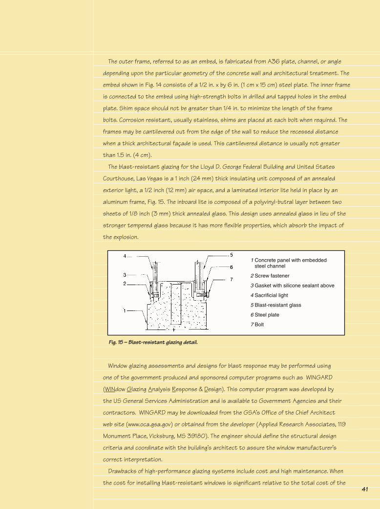
The blast-resistant glazing for the Lloyd D. George Federal Building and United States
Courthouse, Las Vegas is a 1 inch (24 mm) thick insulating unit composed of an annealed
exterior light, a 1/2 inch (12 mm) air space, and a laminated interior lite held in place by an
aluminum frame, Fig. 15. The inboard lite is composed of a polyvinyl-butral layer between two
sheets of 1/8 inch (3 mm) thick annealed glass. This design uses annealed glass in lieu of the
stronger tempered glass because it has more flexible properties, which absorb the impact of
the explosion.
Window glazing assessments and designs for blast response may be performed using
one of the government produced and sponsored computer programs such as WINGARD
(WINdow Glazing Analysis Response & Design). This computer program was developed by
the US General Services Administration and is available to Government Agencies and their
contractors. WINGARD may be downloaded from the GSA’s Office of the Chief Architect
web site (www.oca.gsa.gov) or obtained from the developer (Applied Research Associates, 119
Monument Place, Vicksburg, MS 39180). The engineer should define the structural design
criteria and coordinate with the building’s architect to assure the window manufacturer’s
correct interpretation.
Drawbacks of high-performance glazing systems include cost and high maintenance. When
the cost for installing blast-resistant windows is significant relative to the total cost of the
Fig. 15 – Blast-resistant glazing detail.
1 Concrete panel with embedded steel channel
2 Screw fastener
3 Gasket with silicone sealant above
4 Sacrificial light
5 Blast-resistant glass
6 Steel plate
7 Bolt

42
building, resources allocated to protective design may be better applied toward upgrading the
structural frame to be blast resistant. This is because the blast pressures from a close in
car or truck bomb can far exceed the allowable pressures any window system can resist. As a
point of reference, façade blast pressures in the Oklahoma City bombing were on the order of
4,000 psi - 100 times higher than the design pressures described above.
Atriums incorporating large vertical glazed openings on the building façade, common in
prestigious office buildings, cannot be designed to withstand blast pressures from a close-
in explosion. It is not reasonable to harden the exterior walls of the structure and leave an
atrium’s exterior wall of this type as an inviting target. Atrium balcony parapets, spandrel
beams, and exposed slabs must be strengthened to withstand loads that are transmitted
through exterior glass or framing. Another approach is to use an internal atrium with no
outward facing windows or an atrium with clerestory windows that are close to the ceiling and
angling the windows away from the curb to reduce the pressure levels.
The initial construction cost of protection has two components; fixed and variable. Fixed
costs include such items as security hardware and space requirements. These costs do not
depend on the level of an attack; that is, it costs the same to keep a truck away from a
building whether the truck contains 500 or 5000 lbs. of TNT. Blast protection, on the other
hand, is a variable cost. It depends on the threat level, which is a function of the explosive
charge weight and the stand-off distance.
The optimal stand-off distance is determined by defining the total cost of protection as
the sum of the cost of protection (construction cost) and the cost of stand-off (land cost).
These two costs are considered as a function of the stand-off for a given explosive charge
weight. The cost of protection is assumed to be proportional to the peak pressure at the
building envelope, and the cost of land is a function of the square of the stand-off distance.
The optimal stand-off is the one that minimizes the sum of these costs.
If additional land is not available to move the secured perimeter farther from the building,
the required floor area of the building can be distributed among additional floors. As the
number of floors is increased, the footprint decreases, providing an increased stand-off
distance. Balancing the increasing cost of the structure (due to the added floors) and the
corresponding decrease in protection cost (due to added stand-off), it is possible to find the
optimal number of floors to minimize the cost of protection.
Though it is difficult to assign costs to various upgrade measures because they vary
based on the site specific design, some generalizations can be made (see Fig. 16). In some
cases, the owner may decide to prioritize enhancements, based on their effectiveness in
saving lives and reducing injuries. For instance, measures against progressive collapse are
perhaps the most effective actions that can be implemented to save lives and should be
Initial Costs

43
considered above any other upgrades. Laminated glass is perhaps the single most effective
measure to reduce extensive non-fatal injuries.
An awareness of a blast threat from the beginning of a project helps to decide early what
the priorities are for the facility. Including protective measures as part of the discussion
regarding trade-offs early in the design process often helps to clarify the issues.
Ultimately the willingness to pay the additional cost for protection against blast hazards
is a function of the “probability of regrets” in the event a sizable incident occurs. In some
situations, the small probability of an incident may not be compelling enough to institute
the design enhancements. Using this type of logic, it is likely to lead to a selection process
in which buildings stratify into two groups: those that incorporate no measures at all or only
the most minimal provisions and those that incorporate high levels of protection. It also
leads to the conclusion that it may not be appropriate to consider any but the most minimal
measures for most buildings.
���������������������������������������������������
����
����
����
�����
���
����
���
����
���
����
�������������
���������������������������������
�� �� �����
����������������
�������������������
������������������������������������
������������
������������������� ����������������
�������� ���������������
����������������������
Fig. 16 – Plots showing relationship between cost of upgrading various building components, standoff distance, and risk.Source: Federal Emergency Management Agency. Primer for Design of Commercial Buildings to Mitigate Terrorist Attacks. FEMA 427 (Washington, DC: Federal Emergency Management Agency, December 2003).