designing of all terrain eco-green vehicle (atv) · catia software. later the design is ......
TRANSCRIPT

International Journal of Engineering Trends and Technology (IJETT) – Volume 54 Issue 3- December 2017
ISSN: 2231-5381 http://www.ijettjournal.org Page 180
Designing of All Terrain Eco-Green Vehicle
(ATV) Venu Gopal Prathimala
1, Pradeep Varma Pericherla
2, Roshan Puvvada
3, Nithin Mane
4
1,2,3,4 B.Tech, Mechanical Engineering, GITAM (deemed to be University)
Visakhapatnam, Andhra Pradesh, INDIA.
Abstract—This paper provides an in-detail
description of the design considerations, static &
dynamic analysis and mathematical data involved in
the design of an ELECTRIC MOTOR POWERED ALL
TERRAIN VEHICLES (ATV). The main objective of
this paper is to reduce the weight of the electric
powered vehicles and to design a vehicle which works
efficiently in the emerging electric vehicle sector. In
order to maintain the speed levels of the vehicle,
seamless decision were made in motor selection. The
main focus had been laid on the simplicity of the
design, high performance, easy maintenance and
safety at a very affordable price. The design and
development comprise of material selection, chassis
and frame design, cross section determination,
determining strength requirements of roll cage, stress
analysis and simulations to test the ATV against
failure [1]. During the entire design process,
consumer interest through innovative, inexpensive,
and effective methods was always the priority. Most of
the components have been chosen based on their easy
availability and reliability. According to recognition
of customer’s need the vehicle is designed to be
ergonomic, aerodynamic, highly engineered and
easily manufactured. Hence, it makes the vehicle more
efficient. This vehicle can navigate through almost all
terrains, which ultimately is the main purpose behind
the making of any all-terrain vehicle [5].
This report tries to summarize the steps taken in
finalizing the design and analysis of the all-terrain
vehicle (ATV) in a nutshell.
Keywords—All Terrain Vehicle, Modelling, FEA,
Roll cage, Strength, Stiffness, Impact loads.
I. INTRODUCTION
The aim of the study is to determine the best design
for the new age of eco-green vehicles that would
provide maximum efficiency in consideration of fuel
utilization and to develop the roll cage for All-Terrain
Vehicle. The material used for the roll cage is selected
based on strength, cost and availability. A software
model is prepared in SOLID-WORKS software and
CATIA software. Later the design is tested against all
modes of failure by conducting various simulations
and stress analysis with the aid of ANSYS Software
(14). Based on the result obtained from these tests the
design is modified accordingly. After successfully
designing the roll cage, it is ready for the fabrication.
As weight is the critical aspect in a vehicle which is
powered by a small electric motor, balance must be
found between the strength and weight of the design.
This design is both cost efficient and has a good
strength [1, 2]. The chassis is the component in charge
of supporting all other vehicle’s subsystems and also
to safeguard the driver at all time. The chassis design
needs to be prepared for impacts that take place in any
certain crash or rollover. Thus, the design of chassis
plays a vital role in the designing of an ATV.
II. DESIGN METHODOLOGIES
A. Main design focus-
The main design of the vehicle is focused on lighter
and more rigid and ascetics oriented frame, robust
suspension design and a more versatile drive train. In
addition, the design of steering and braking with high
safety and precision was aimed at. It is also necessary
to keep weight of the roll cage as low as possible to
achieve better acceleration and it is also important to
maintain the Centre of gravity of the as low as
possible to avoid toppling. [3] Mounting heavier
components such as engine, driver seat etc., directly
on chassis is one way of achieving low Centre of
gravity.
B. Frame Design-
The objective of the chassis is to encapsulate all
components of the car, including a driver, efficiently
and safely. Principal aspects of the chassis is focused
during the design and implementation which includes
driver safety, suspension and drive train integration,
structural rigidity, weight, and operator ergonomics.
The number one priority in the chassis design was
driver safety.
C. Design Considerations-
The goals for the roll cage design include [2]:
Increase comfort for the driver.
Decreased weight, and overall length.
Improved packaging for subsystems.
Aesthetic considerations.
Attractive design.
Durable.
Lower C.G value.

International Journal of Engineering Trends and Technology (IJETT) – Volume 54 Issue 3- December 2017
ISSN: 2231-5381 http://www.ijettjournal.org Page 181
Material Selection: Material selection is one of the
key factors in designing the frame of the ATV as it is
the measure of safety, reliability, performance and
strength of the roll cage. To ensure that the optimal
material is chosen, extensive research was carried out
and the results were compared with materials from
multiple categories [3]. Since safety of driver is
paramount to us, the roll cage is required to have
adequate factor of safety even in worst case scenario.
The strategy behind selecting the material for roll cage
was to achieve maximum welding area, good bending
stiffness, minimum weight and maximum strength for
the pipes. So after market analysis on cost, availability
and properties of many materials it is concluded that
using either AISI 1018 or AISI 4130 are the best
options. Among these materials AISI 4130 is chosen
due to the following reasons which were observed
from the comparison table as shown in Table 1 [6]:
Table 1: Material Comparison Chart.
D. Size Specifications of Material-
In order to reduce the weight of the roll cage, different
sizes of the tubes were considered in.
Primary tubes:
Normalized Al-Si4130 Chrome-Moly Steel.
Outer diameter—31.75mm
Wall thickness—1.65mm
Secondary tubes:
Outer diameter—25.4mm
Wall thickness—1.65mm
E. Design Stage:
A number of models of the roll cage were designed
and modified to reach the design considerations. The
frame was designed using CATIA and
SOLIDWORKS packages and analysis was performed
in ANSYS.
The main steps to be followed while designing the
frame of the vehicle are:
Proper clearances must be maintained
between the driver and the frame by taking
the measurements of the common driver
dimensions.
Wheel base and track width must be fixed
initially before designing the roll cage.
Proper leg room must be provided.
F. Bending strength & stiffness calculation:
The bending strength of a material is given by the
bending moment equation [4].
𝑀
𝐼 =
𝜎
𝑌=
𝐸
𝑅
Where
M is the bending moment/strength
I is the moment of inertia
σ is the bending stress
Y is the distance from the neutral axis
E is the young’s modulus.
From the above bending moment equation
𝑀 = 𝜎 ∗ 𝐼
𝑌
Where I Is the moment of inertia is given by
𝐼 =𝜋
64(𝐷0
4 − 𝐷𝑖4)
Similarly bending stiffness is given by the equation:
𝐵𝑒𝑛𝑑𝑖𝑛𝑔 𝑠𝑡𝑖𝑓𝑓𝑛𝑒𝑠𝑠 = 𝐸 ∗ 𝐼
For AISI 1018:
1. For pipe 1 with given dimensions :-
Outside diameter 𝐷0 = 2.54 cm
Wall thickness (t) = 0.304 cm
Inner diameter 𝐷𝑖 = 𝐷0 − 2𝑡 =2.54 – (2*0.304)
𝐷𝑖 = 1.932 cm.
Bending strength = 390456 N-mm.
Bending stiffness = 278.507*107 N-mm
2.
2. For pipe 2 with given dimensions :-
Outside diameter 𝐷0 = 3.175 cm
Wall thickness (t) = 0.165 cm
Inner diameter 𝐷𝑖 = 𝐷0 − 2𝑡
Material 1018 steel 4130 steel
outside diameter 2.54cm 3.175cm
wall thickness 0.304cm 0.165cm
bending stiffness 3791.1N/m2
3635.1
N/m2
bending strength 391.3N-m 487N-m
Weight perimeter 1.686kg 1.229kg
young’s modulus 205Gpa 190-
210Gpa
poisons ratio 0.29 0.27-
0.30
carbon content 0.14-0.2 0.28-
0.33
Tensile yield
strength
365 MPa 460 MPa
International Journal of Engineering Trends and Technology (IJETT) – Volume 54 Issue 3- December 2017
ISSN: 2231-5381 http://www.ijettjournal.org Page 182
=3.175 – (2*0.165)
𝐷𝑖= 2.845 cm.
Bending strength =407291.4 N-mm.
Bending stiffness = 363.144*107 N-mm
2.
3. For pipe 3 with given dimensions :-
Outside diameter 𝐷0 = 2.54 cm
Wall thickness (t) = 0.165 cm
Inner diameter 𝐷𝑖 = 𝐷0 − 2𝑡
=2.54 – (2*0.165)
𝐷𝑖 = 2.21 cm.
Bending strength =250550.2 N-mm.
Bending stiffness = 178.714*107 N-mm
2.
FOR AISI 4130:
4. For pipe 1 with given dimensions :-
Outside diameter 𝐷0 = 2.54 cm
Wall thickness (t) = 0.304 cm
Inner diameter 𝐷𝑖 = 𝐷0 − 2𝑡 =2.54 – (2*0.304)
𝐷𝑖 = 1.932 cm.
Bending strength = 492081.6 N-mm.
Bending stiffness =285.300*107 N-mm
2.
5. For pipe 2 with given dimensions :-
Outside diameter 𝐷0 = 3.175 cm
Wall thickness (t) = 0.165 cm
Inner diameter 𝐷𝑖 = 𝐷0 − 2𝑡
=3.175 – (2*0.165)
𝐷𝑖= 2.845 cm.
Bending strength = 513298.8 N-mm
Bending stiffness = 372.002*107 N-mm
2.
6. For pipe 3 with given dimensions :-
Outside diameter 𝐷0 = 2.54 cm
Wall thickness (t) = 0.165 cm
Inner diameter 𝐷𝑖 = 𝐷0 − 2𝑡 =2.54 – (2*0.165)
𝐷𝑖= 2.21cm.
Bending strength = 315761.9 N-mm.
Bending stiffness =183.073*107 N-mm
2.
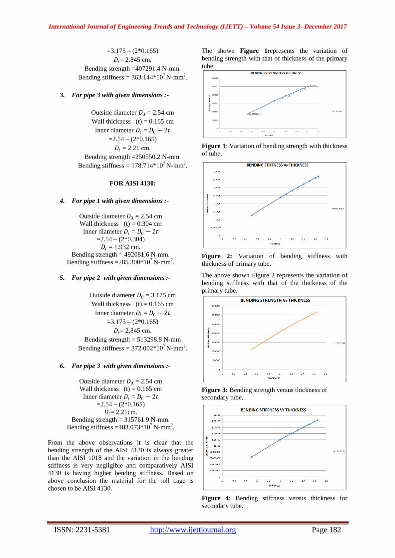
From the above observations it is clear that the
bending strength of the AISI 4130 is always greater
than the AISI 1018 and the variation in the bending
stiffness is very negligible and comparatively AISI
4130 is having higher bending stiffness. Based on
above conclusion the material for the roll cage is
chosen to be AISI 4130.
The shown Figure 1represents the variation of
bending strength with that of thickness of the primary
tube.
Figure 1: Variation of bending strength with thickness
of tube.
Figure 2: Variation of bending stiffness with
thickness of primary tube.
The above shown Figure 2 represents the variation of
bending stiffness with that of the thickness of the
primary tube.
Figure 3: Bending strength versus thickness of
secondary tube.
Figure 4: Bending stiffness versus thickness for
secondary tube.

International Journal of Engineering Trends and Technology (IJETT) – Volume 54 Issue 3- December 2017
ISSN: 2231-5381 http://www.ijettjournal.org Page 183
The above shown Figure 2 & Figure 4 represents the
variation of bending strength and bending stiffness
with that of the thickness of the secondary tube.
Thickness Strength Thickness Stiffness
1.65 513298.8 1.65 3.72E+09
1.6 500134.8 1.6 3.62E+09
1.5 473388.5 1.5 3.43E+09
1.4 446078.2 1.4 3.23E+09
1.3 418196 1.3 3.03E+09
1.2 389733.9 1.2 2.82E+09
1.1 360684 1.1 2.61E+09
1 331038.2 1 2.4E+09
0.5 173586.1 0.5 1.26E+09
Table 2: Data for strength and stiffness versus
thickness graphs for primary tube.
Thickness Strength Thickness Stiffness
1.65 315761.9 1.65
183073237
6
1.6 308037.1 1.6
178594533
6
1.5 292271.2 1.5
169453774
2
1.4 276077.4 1.4
160064866
1
1.3 259447.9 1.3
150423358
3
1.2 242374.9 1.2
140524760
4
1.1 224850.7 1.1
130364542
2
1 206867.4 1 119938131
0.5 109783.5 0.5 636505385
Table 3: Data for strength and stiffness versus
thickness graphs for secondary tube.
The above shown Table 2 &Table 3 represents the
mathematical data involved in the graphical
representation of strength and stiffness versus
thickness of primary and secondary tubes.
G. Geometry Creation:
The design was done using the CATIA and
SOLIDWORKS software’s. The model was made
fully parametric. This means the features of the model
will change according to any modifications to the
parent features. The usage of parametric design was
extremely important with this design. As so many
factors interact in the design of the frame, the
parametric properties allowed the change of a single
part to automatically change the design of all parts
interacting with it [4].
By fulfilling all the design considerations a 3D model
was designed.
Figure 5: Wireframe model of the roll cage.
The above shown Figure 5 represents the wireframe
model of the roll cage which is designed in CATIA
software package.
Figure 6: Modified wire frame of the roll cage.
The above shown Figure 6 represents the modified
wireframe model of the roll cage which is designed in
CATIA software package.
Figure 7: Fabricated roll cage.
The above shown Figure 7represents the manufactured
model of the roll cage which is designed in CATIA
software package.
Figure 8: Roll cage model with the driver.
International Journal of Engineering Trends and Technology (IJETT) – Volume 54 Issue 3- December 2017
ISSN: 2231-5381 http://www.ijettjournal.org Page 184
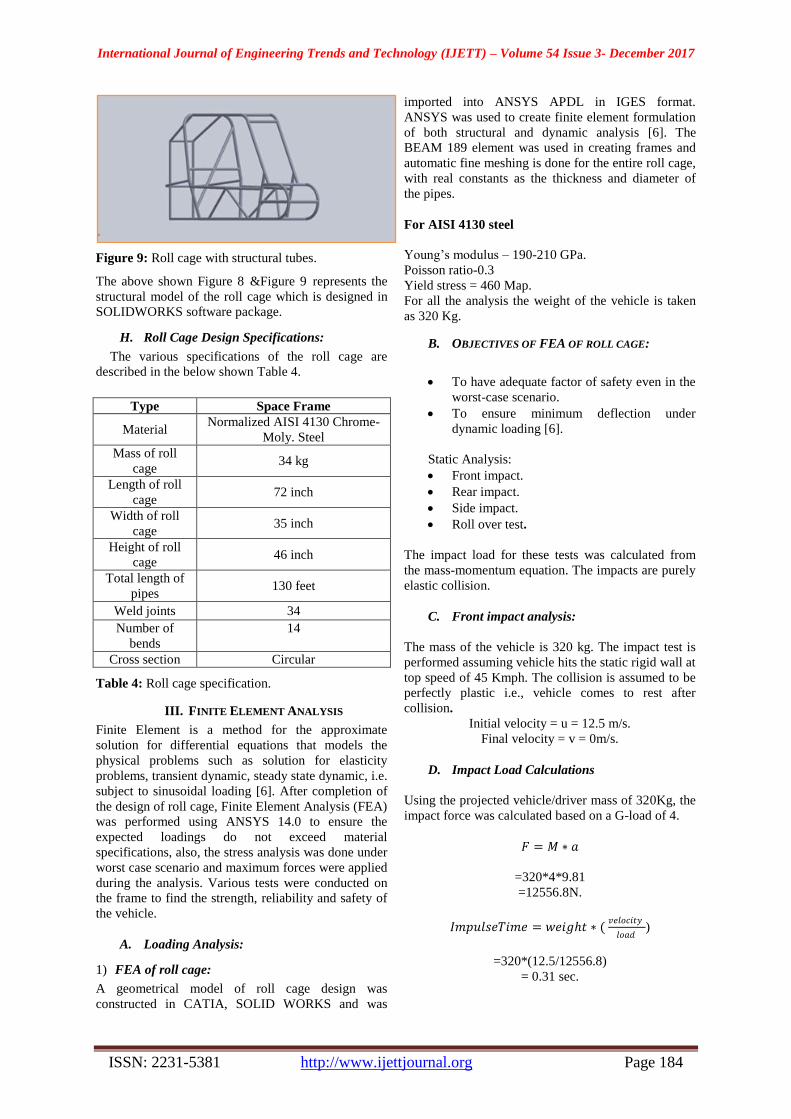
Figure 9: Roll cage with structural tubes.
The above shown Figure 8 &Figure 9 represents the
structural model of the roll cage which is designed in
SOLIDWORKS software package.
H. Roll Cage Design Specifications:
The various specifications of the roll cage are
described in the below shown Table 4.
Type Space Frame
Material Normalized AISI 4130 Chrome-
Moly. Steel
Mass of roll
cage 34 kg
Length of roll
cage 72 inch
Width of roll
cage 35 inch
Height of roll
cage 46 inch
Total length of
pipes 130 feet
Weld joints 34
Number of
bends
14
Cross section Circular
Table 4: Roll cage specification.
III. FINITE ELEMENT ANALYSIS
Finite Element is a method for the approximate
solution for differential equations that models the
physical problems such as solution for elasticity
problems, transient dynamic, steady state dynamic, i.e.
subject to sinusoidal loading [6]. After completion of
the design of roll cage, Finite Element Analysis (FEA)
was performed using ANSYS 14.0 to ensure the
expected loadings do not exceed material
specifications, also, the stress analysis was done under
worst case scenario and maximum forces were applied
during the analysis. Various tests were conducted on
the frame to find the strength, reliability and safety of
the vehicle.
A. Loading Analysis:
1) FEA of roll cage:
A geometrical model of roll cage design was
constructed in CATIA, SOLID WORKS and was
imported into ANSYS APDL in IGES format.
ANSYS was used to create finite element formulation
of both structural and dynamic analysis [6]. The
BEAM 189 element was used in creating frames and
automatic fine meshing is done for the entire roll cage,
with real constants as the thickness and diameter of
the pipes.
For AISI 4130 steel
Young’s modulus – 190-210 GPa.
Poisson ratio-0.3
Yield stress = 460 Map.
For all the analysis the weight of the vehicle is taken
as 320 Kg.
B. OBJECTIVES OF FEA OF ROLL CAGE:
To have adequate factor of safety even in the
worst-case scenario.
To ensure minimum deflection under
dynamic loading [6].
Static Analysis:
Front impact.
Rear impact.
Side impact.
Roll over test.
The impact load for these tests was calculated from
the mass-momentum equation. The impacts are purely
elastic collision.
C. Front impact analysis:
The mass of the vehicle is 320 kg. The impact test is
performed assuming vehicle hits the static rigid wall at
top speed of 45 Kmph. The collision is assumed to be
perfectly plastic i.e., vehicle comes to rest after
collision.
Initial velocity = u = 12.5 m/s.
Final velocity = v = 0m/s.
D. Impact Load Calculations
Using the projected vehicle/driver mass of 320Kg, the
impact force was calculated based on a G-load of 4.
𝐹 = 𝑀 ∗ 𝑎
=320*4*9.81
=12556.8N.
𝐼𝑚𝑝𝑢𝑙𝑠𝑒𝑇𝑖𝑚𝑒 = 𝑤𝑒𝑖𝑔𝑡 ∗ ( 𝑣𝑒𝑙𝑜𝑐𝑖𝑡𝑦
𝑙𝑜𝑎𝑑)
=320*(12.5/12556.8)
= 0.31 sec.
International Journal of Engineering Trends and Technology (IJETT) – Volume 54 Issue 3- December 2017
ISSN: 2231-5381 http://www.ijettjournal.org Page 185
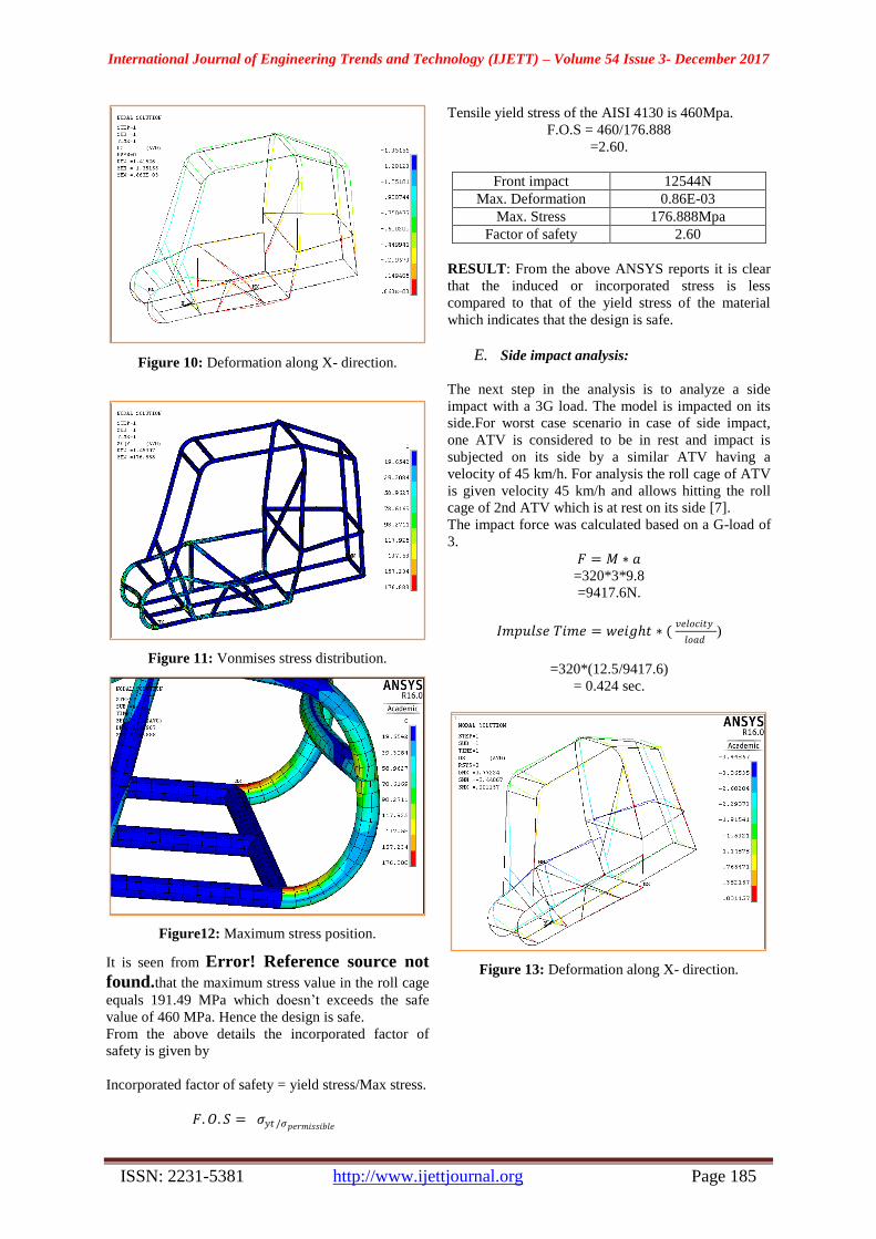
Figure 10: Deformation along X- direction.
Figure 11: Vonmises stress distribution.
Figure12: Maximum stress position.
It is seen from Error! Reference source not
found.that the maximum stress value in the roll cage
equals 191.49 MPa which doesn’t exceeds the safe
value of 460 MPa. Hence the design is safe.
From the above details the incorporated factor of
safety is given by
Incorporated factor of safety = yield stress/Max stress.
𝐹.𝑂. 𝑆 = 𝜎𝑦𝑡 /𝜎𝑝𝑒𝑟𝑚𝑖𝑠𝑠𝑖𝑏𝑙𝑒
Tensile yield stress of the AISI 4130 is 460Mpa.
F.O.S = 460/176.888
=2.60.
Front impact 12544N
Max. Deformation 0.86E-03
Max. Stress 176.888Mpa
Factor of safety 2.60
RESULT: From the above ANSYS reports it is clear
that the induced or incorporated stress is less
compared to that of the yield stress of the material
which indicates that the design is safe.
E. Side impact analysis:
The next step in the analysis is to analyze a side
impact with a 3G load. The model is impacted on its
side.For worst case scenario in case of side impact,
one ATV is considered to be in rest and impact is
subjected on its side by a similar ATV having a
velocity of 45 km/h. For analysis the roll cage of ATV
is given velocity 45 km/h and allows hitting the roll
cage of 2nd ATV which is at rest on its side [7].
The impact force was calculated based on a G-load of
3.
𝐹 = 𝑀 ∗ 𝑎
=320*3*9.8
=9417.6N.
𝐼𝑚𝑝𝑢𝑙𝑠𝑒 𝑇𝑖𝑚𝑒 = 𝑤𝑒𝑖𝑔𝑡 ∗ ( 𝑣𝑒𝑙𝑜𝑐𝑖𝑡𝑦
𝑙𝑜𝑎𝑑)
=320*(12.5/9417.6)
= 0.424 sec.
Figure 13: Deformation along X- direction.

International Journal of Engineering Trends and Technology (IJETT) – Volume 54 Issue 3- December 2017
ISSN: 2231-5381 http://www.ijettjournal.org Page 186
Figure 14: Vonmises stress distribution.
It is seen from Error! Reference source not
found.that the maximum stress value in the roll cage
equals 307.929 Mpa which doesn’t exceeds the safe
value of 460 MPa. Hence the design is safe.
From the above details the incorporated factor of
safety is given by
Incorporated factor of safety = yield stress/Max stress.
Tensile yield stress of the AISI 4130 is 460Mpa.
F.O.S = 460/301.748
=1.52
Side impact 8232 N
Max. Deformation 0.001157 mm
Max. Stress 301.748 Mpa
Factor of safety 1.52
RESULT: From the above ANSYS reports it is clear
that the induced or incorporated stress is less
compared to that of the yield stress of the material
which indicates that the design is safe.
F. Rear Impact Analysis:
The next step is to analyze the model for rear impact
with G-Load of 4.For worst case hit another similar
ATV on its rear part with a maximum scenario in rear
impact, the ATV is considered to velocity of 45 km/h.
For analysis the roll cage of 2nd ATV is given a
velocity of 45 km/h and allows hitting the roll cage of
1st ATV which is at rest on its rear part [7].
𝐹 = 𝑀 ∗ 𝑎
=320*4*9.8
=12556.8 N.
𝐼𝑚𝑝𝑢𝑙𝑠𝑒 𝑇𝑖𝑚𝑒 = 𝑤𝑒𝑖𝑔𝑡 ∗ ( 𝑣𝑒𝑙𝑜𝑐𝑖𝑡𝑦
𝑙𝑜𝑎𝑑)
=320*(12.5/10976)
= 0.364 sec.
Figure 15: Deformation along X-axis.
Figure 16: Vonmises stress distribution.
Figure 17: Maximum stress distribution.
It is seen from Error! Reference source not
found.that the maximum stress value in the roll cage
equals 198.726 Mpa which doesn’t exceeds the safe
value of 460 MPa. Hence the design is safe.
From the above details the incorporated factor of
safety is given by
Incorporated factor of safety = yield stress/Max stress.

International Journal of Engineering Trends and Technology (IJETT) – Volume 54 Issue 3- December 2017
ISSN: 2231-5381 http://www.ijettjournal.org Page 187
Tensile yield stress of the AISI 4130 is 460Mpa.
F.O.S = 460/196.823
=2.337.
Rear impact 12544N
Max. Deformation 2.7102 mm
Max. Stress 196.823 Mpa
Factor of safety 2.33
RESULT: From the above ANSYS reports it is clear
that the induced or incorporated stress is less
compared to that of the yield stress of the material
which indicates that the design is safe.
G. Roll Over Impact Analysis:
The final step in the analysis was to analyze the stress
on the roll cage caused by a roll over with a G-Load
of2.5 on the frame.
In roll over impact, ATV is considered to be dropped
on its roof on road or ground from a height of 10
feet.10 feet for the drop height is selected because it is
sufficiently greater than anything expected at the
event site. Since road and ground are non-deformable
bodies [7].
𝐹 = 𝑀 ∗ 𝑎
=320*2.5*9.8
=7848 N.
𝐼𝑚𝑝𝑢𝑙𝑠𝑒 𝑇𝑖𝑚𝑒 = 𝑤𝑒𝑖𝑔𝑡 ∗ ( 𝑣𝑒𝑙𝑜𝑐𝑖𝑡𝑦
𝑙𝑜𝑎𝑑)
=320*(12.5/7848)
= 0.509 sec.
Figure 18: Deformation along X-axis.
Figure 19: Vonmises stress distribution.
Figure 20: Maximum stress distribution.
It is seen from Error! Reference source not
found.that the maximum stress value in the roll cage
equals 233.782MPa which doesn’t exceeds the safe
value of 460 MPa. Hence the design is safe.
From the above details the incorporated factor of
safety is given by
Incorporated factor of safety = yield stress/Max stress.
Tensile yield stress of the AISI 4130 is 460Mpa.
F.O.S = 460/233.782
=1.96.
Roll Over impact 7848 N
Max. Deformation 0.2819 mm
Max. Stress 233.782 Mpa
Factor of safety 1.96.
RESULT: From the above ANSYS reports it is clear
that the induced or incorporated stress is less
compared to that of the yield stress of the material
which indicates that the design is safe.

International Journal of Engineering Trends and Technology (IJETT) – Volume 54 Issue 3- December 2017
ISSN: 2231-5381 http://www.ijettjournal.org Page 188
IV. CONCLUSIONS
The project aimed at designing, analyzing,
fabrication and testing of the roll cage. The design is
first conceptualized based on the personal experiences
and intuition. Engineering principles and design
processes are then used to verify and create a vehicle
with optimal performance, safety, manufacturability,
and ergonomics. The roll cage has been designed and
fabricated to the best of its possible. The design
process included using solid works, CATIA and
ANSYS software packages to model, simulate, and
assist in the analysis of the completed vehicle. The
primary objective of this project is to identify and
determine the design parameters of the vehicle with a
proper study of vehicle dynamics. This project helped
us to study and analyze the procedure for vehicle roll
cage and to identify the performance affecting
parameters. It also helps us to understand and
overcome the theoretical difficulties of vehicle design.
The entire designing and manufacturing period was a
great experience for the team as we were introduced
into the amazing world of automobile engineering. It
was a learning experience in which we were the proud
beneficiaries.
REFERENCES
[1] Sandeep Garg, Ravi Shankar Raman, ―Design analysis of the roll cage for all - terrain vehicle,‖ International Journal of
Research in Engineering and Technology (IJRET).,eISSN:
2319-1163 | pISSN: 2321-Volume: 02 Issue: 09 | Sep-2013.
[2] Khelan Chaudhari, Amogh Joshi & Ranjit Kunte, Design
And Development Of Roll Cage For An Allterrain Vehicle, International Journal on Theoretical and Applied Research in
Mechanical Engineering (IJTARME), ISSN : 2319 – 3182,
Volume-2, Issue-4, 2013.
[3] Herb Adams, ―Chassis Engineering‖, Berkley Publishing
Group New York.
[4] F. L. Singer , ―Strength of Materials‖, Harper and Row
Publishers, New York.
[5] UpendraS.Gupta,SumitChandak,,Devashish Dixit, ―Design
& Manufacturing of All Terrain Vehicle (ATV)- Selection, Modification , Static & Dynamic Analysis of ATV
Vehicle‖International Journal of Engineering Trends and
Technology (IJETT) – Volume 20 Number 3 – Feb 2015.
[6] Deep Shrivastava, ―Designing of All Terrain Vehicle
(ATV)‖International Journal of Scientific and Research Publications, Volume 4, Issue 12, December 2014 1 ISSN
2250-3153.
[7] Bharat Kumar Sati, PrashiUpreti ,AnirudhTripathi& Shankar
Batra,‖Static and Dynamic Analysis of the Roll Cage for an All-Terrain Vehicle‖Imperial Journal of Interdisciplinary
Research (IJIR) Vol-2, Issue-6, 2016 ISSN: 2454-1362.
[8] Thomas D. Gillespie; Fundamental of Vehicle Dynamics;
ISBN; 978-1-56091-199-9; February 1992.