desktop 554a - gdc.com
TRANSCRIPT

Fractional T1Data Service Unit
DeskTop 554A
GDC 048R148-000Issue 2, August 1998
Installation and Operation
General DataComm

Trademarks and Patents
General DataComm, the General DataComm logo and the following are trademarks of General DataComm, Inc. in the United States and other countries: ACCULINE, ANALOOP, AUTOFRAME, BERT 901, DATA-COMM SECURE-PAK, DATALOOP, DIGIDIAL, ENmacs, FASTPRO, FIRST RESPONSE, GDC, GDC APEX, GENERAL DATACOMM X-PRESS, GEN*NET, GEN*PAC, IMAGE*TMS, KILOMUX, LAN*TMS, MEGA*BRIDGE, MEGAMUX, MEGAMUX TMS, MEGANET, MEGA-SPLIT, MEGASWITCH, MEGAVIEW, NETCON, NETSWITCH, NMC, QUIKSHIPPERS, SERVI-CHECK, SERVI-SNAP, WINmacs.
All other products or services mentioned in this document are identified by the trademarks, service marks, or product names as designated by the companies who market those products. Inquiries concerning such trade-marks should be made directly to those companies.
Copyright
© 1998 General DataComm, Inc. All rights reserved.
P.O. Box 1299, Middlebury, Connecticut 06762-1299 U.S.A.
This publication and the software it describes contain proprietary informa-tion. No part of this document may be copied, photocopied, reproduced, translated or reduced to any electronic or machine-readable format with-out prior written permission of General DataComm, Inc.
The information in this document is subject to change without notice. General DataComm assumes no responsibility for any damages arising from the use of this document, including but not limited to, lost revenue, lost data, claims by third parties, or other damages. If you have comments or suggestions concerning this manual, please write to Technical Publica-tions or call 1-203-758-1811.

Table of Contents
1-1
1-1
1-2
1-2
1-3
2-1
2-1
2-1
2-2
-2
-13
13
15
-16
16
3-1
3-1
3-3
Preface
1 Technical Overview
Overview............................................................................
DT 554A DSU Features.....................................................
Description .........................................................................
Fractional T1 Capabilities ..................................................
DTE Interface.....................................................................
2 Installation
Overview............................................................................
Unpacking and Handling ...................................................
Preoperational Check .........................................................
Option Selection.................................................................
Timing Options............................................................ 2
Connections...................................................................... 2
DTE Interface Port Connection ................................. 2-
Network Connection.................................................. 2-
Primary Power Connection........................................ 2
Terminal Connection ................................................. 2-
3 Operation
Overview............................................................................
Controls and Indicators ......................................................
Terminal Interface..............................................................
GDC 048R148-000-02

iv Table of Contents
-3
3-8
10
12
4-1
4-4
4-8
-10
11
-13
13
-14
-16
-17
-19
21
21
3
Configuration............................................................... 3
Diagnostics ..................................................................
Monitor ...................................................................... 3-
What Are You?.......................................................... 3-
4 Tests
Overview............................................................................
Terminal Interface Test Procedure.....................................
Network QRSS Self Test ...................................................
Network Payload Loopback............................................. 4
Network Line Loopback .................................................. 4-
Network Local Test.......................................................... 4
Network Local Test with QRSS Self Test ....................... 4-
Network Remote Test ...................................................... 4
Network Remote Test with QRSS Self Test .................... 4
DTE Self Test................................................................... 4
DTE Local Loopback....................................................... 4
DTE Digital Loopback..................................................... 4-
DTE Remote Digital Loopback ....................................... 4-
DTE Remote Digital Loopback with Self Test ................ 4-2
A Technical Characteristics
B DTE Interface Signals
C Timing Options
D Alarm Definitions
GDC 048R148-000-02
Table of Contents v
3
-13
14
-2
4
-9
-10
-11
-12
-3
-4
-7
9
9
-11
12
12
-13
14
-15
-15
-16
-17
-18
19
20
20
Figures
2-1 Position of Configuration Option Switchbanks .......... 2-
2-2 Back Panel Connectors ............................................... 2
2-3 EIA-530 Interface Daughter Card Installation............ 2-
3-1 DT 554A Front Panel Controls and Indicators ........... 3
3-2 Configuration Screen, with Default Settings .............. 3-
3-3 Diagnostics Selection Screen...................................... 3
3-4 Diagnostics Results Screen......................................... 3
3-5 Monitor Screen ........................................................... 3
3-6 What Are You? Screen ............................................... 3
4-1 Fault Isolation Procedure ............................................ 4
4-2 Diagnostics Selection Screen...................................... 4
4-3 Diagnostics Results Screen......................................... 4
4-4 Data Path for Network End-to-End Self Test ............. 4-
4-5 Network End-to-End Self Test, Front Panel Control.. 4-
4-6 Data Path for Network Payload Loopback ................. 4
4-7 Data Path for Network Line Loopback....................... 4-
4-8 Network Line Loopback, Front Panel Control ........... 4-
4-9 Data Path for Network Local Test .............................. 4
4-10 Network Local Test, Front Panel Control................... 4-
4-11 Data Path for Network Remote Test........................... 4
4-12 Network Remote Test, Front Panel Control ............... 4
4-13 Data Path for Network Remote Test with Self Test ... 4
4-14 Network Remote Test with Self Test, Front Panel Control..................................................... 4
4-15 Data Path for DTE End-to-End Self Test ................... 4
4-16 DTE End-to-End Self Test, Front Panel Control ........ 4-
4-17 Data Path for DTE Local Loopback ........................... 4-
4-18 DTE Local Loopback, Front Panel Control................ 4-
GDC 048R148-000-02
vi Table of Contents
21
22
-22
-23
-24
-4
-4
-6
-8
-9
-10
-11
-12
5
4-19 Data Path for DTE Digital Loopback ......................... 4-
4-20 Data Path for DTE Remote Digital Loopback............ 4-
4-21 DTE Remote Digital Loopback, Front Panel Control..................................................... 4
4-20 Data Path for DTE Remote Digital Loopback with Self Test .............................................................. 4
4-21 DTE Remote Digital Loopback with Self Test, Front Panel Control..................................................... 4
Tables
1-1 Equipment List............................................................ 1
2-1 Option Application Notes – Switchbank S13,CSU Characteristics .................................................... 2
2-2 Option Application Notes – Switchbank S14,Network Characteristics.............................................. 2
2-3 Option Application Notes – Switchbank S15,DTE Characteristics .................................................... 2
2-4 Option Application Notes – Switchbank S10,DTE Characteristics .................................................... 2
2-5 Option Application Notes – Switchbanks S11 & S12,DS0 Assignments........................................................ 2
2-6 DTE Data Rate Selection – Switchbank S12.............. 2
2-7 DTE Starting DS0 Selections – Switchbank S11 ....... 2
3-1 DT 554A Configuration Option Settings.................... 3-
GDC 048R148-000-02

Preface
n is
, ent
pc
nal
5
ScopeThis manual describes how to install and configure a General DataComm Desktop 554A Data Service Unit. It is written for installers, service technicians, and users. It assumes a working knowledge of data interfaces, and T1 and Fractional T1 data transmission services.
Revision HistoryThis is the initial issue of the manual.
OrganizationThis manual has four chapters and four appendices. The informatioarranged as follows:
• Chapter 1 - Technical Overview describes the Data Service Unitits features, and its options. This chapter contains the EquipmList table.
• Chapter 2 - Installation provides directions for installing the DSUand configuring it by means of the switchbanks located on theboard.
• Chapter 3 - Operation describes the use of both the DSU front panel controls and indicators, and the VT100-compatible termiinterface that can be accessed through the Console port.
• Chapter 4 - Tests describes tests that can be performed on the DSU.
• Appendix A - Technical Characteristics
• Appendix B - DTE Interface Signals lists pin/signal assignments for the two DTE interfaces that the DSU can support: ITU-T V.3and EIA-530.
GDC 048R148-000-02

viii Preface
n
r
ec-
• Appendix C - Timing Options illustrates the arrangements that cabe used to provide transmit timing for the DSU.
• Appendix D - A larm Definitions identifies the conditions that cancause the DSU to generate an alarm.
Document Conventions
Level 1 paragraph headers introduce major topics.
Level 2 paragraph headers introduce subsections of majotopics.
Level 3 paragraph headers introduce subsections of sondary topics.
This typewriter font shows output that is displayed on the screen.
This bold font shows specific input that you type at the keyboard.
This bold italicized font shows vari-able input that you type at the key-board.
Notes present special instructions, helpful hints or general rules.
NOTE
GDC 048R148-000-02

Preface ix
es
s pore
port ess
Service Support and TrainingVITAL Network Services, a General DataComm company, is committed to providing the service support and training needed toinstall, manage, and maintain your GDC equipment.
GDC’s VITAL Network Services provides hands-on training coursthrough VITAL Network Services Global Technology Training Services. Courses range from basic data communications, modemand multiplexers, to complex network and ATM systems. Trainingcourses are available at our centers in the US, UK, France, Singaand Mexico, as well as at a customer’s site.
For more information regarding GDC's VITAL Network Services’ service programs, training courses, or for assistance with your suprequirements, contact GDC's VITAL Network Services at the addror phone number listed below, or visit our website at: http//www.vitalnetsvc.com
VITAL Network Services World Headquarters6 Rubber AvenueNaugatuck, Connecticut 06770 USA
North America: 1 800 243 10301 888 248 48251 203 729 2461
Training Information: 1 203 729 0271French Speaking Canada:1 800 361 2552North America Fax: 1 203 723 5012
1 203 729 761
GDC 048R148-000-02
x Preface
1
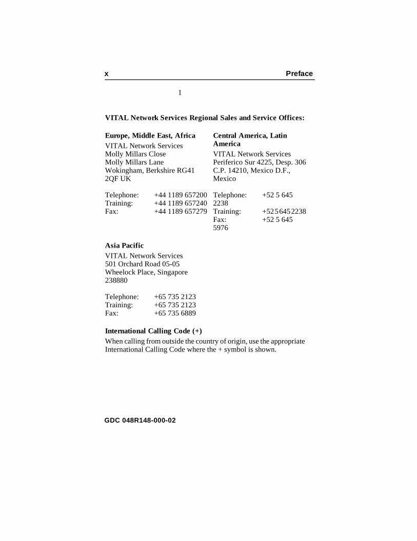
VITAL Network Services Regional Sales and Service Offices:
Europe, Middle East, AfricaVITAL Network ServicesMolly Millars CloseMolly Millars LaneWokingham, Berkshire RG41 2QF UK
Telephone: +44 1189 657200Training: +44 1189 657240Fax: +44 1189 657279
Central America, Latin AmericaVITAL Network ServicesPeriferico Sur 4225, Desp. 306C.P. 14210, Mexico D.F., Mexico
Telephone: +52 5 645 2238Training: +52 5 645 2238Fax: +52 5 645 5976
Asia PacificVITAL Network Services501 Orchard Road 05-05Wheelock Place, Singapore 238880
Telephone: +65 735 2123Training: +65 735 2123Fax: +65 735 6889
International Calling Code (+)When calling from outside the country of origin, use the appropriateInternational Calling Code where the + symbol is shown.
GDC 048R148-000-02
Preface xi
tic ildup
y SD the , use
an r
ion r
.
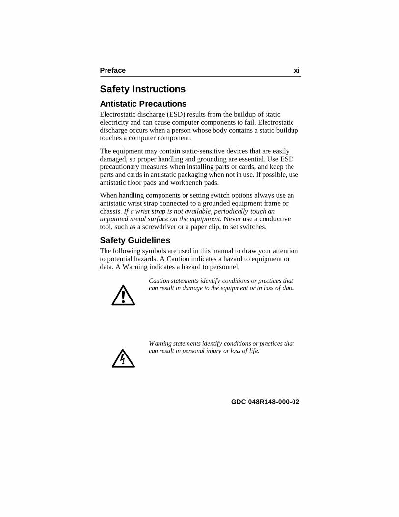
Safety InstructionsAntistatic PrecautionsElectrostatic discharge (ESD) results from the buildup of static electricity and can cause computer components to fail. Electrostadischarge occurs when a person whose body contains a static butouches a computer component.
The equipment may contain static-sensitive devices that are easildamaged, so proper handling and grounding are essential. Use Eprecautionary measures when installing parts or cards, and keep parts and cards in antistatic packaging when not in use. If possibleantistatic floor pads and workbench pads.
When handling components or setting switch options always use antistatic wrist strap connected to a grounded equipment frame ochassis. If a wrist strap is not available, periodically touch an unpainted metal surface on the equipment. Never use a conductive tool, such as a screwdriver or a paper clip, to set switches.
Safety GuidelinesThe following symbols are used in this manual to draw your attentto potential hazards. A Caution indicates a hazard to equipment odata. A Warning indicates a hazard to personnel.
Caution statements identify conditions or practices thatcan result in damage to the equipment or in loss of data
Warning statements identify conditions or practices thatcan result in personal injury or loss of life.
GDC 048R148-000-02
xii Preface
one ent
dard
es
ork e
if l be cal, r y
Always use caution and common sense. To reduce the risk of electricalshock, do not operate any equipment with the cover removed. Repairs must be performed by qualified service personnel only.
Regulatory NoticesFCC Part 68 ComplianceConnection of data communications equipment to the public telephnetwork is regulated by FCC Rules and Regulations. This equipmcomplies with Part 68 of these regulations which require all of thefollowing:
All connections to the telephone network must be made using stanplugs and telephone company provided jacks or equivalent. Connection of this equipment to party lines and coin telephones isprohibited. A label on the bottom of the DT 554A enclosure providthe FCC Registration number for the unit. If requested, give this information to the telephone company.
To connect the DeskTop 554A DSU to the Public Telephone Netwyou are required to give the following information to the TelephonCompany:
The telephone company may discontinue your service temporarilythe unit causes harm to the telephone network. If possible, you wilnotified of such an action in advance. If advance notice is not practiyou will be notified as soon as possible and will be advised of youright to file a complaint with the FCC. The telephone company machange its communication facilities, equipment, operations and procedures where reasonably required for operation. If so, the telephone company will notify you in writing. All repairs or
FCC Registration Number: AG6USA-24144-DE-NFIC (Facility Interface Code): 04DU9-DN, 04DU9-BN,
04DU9-1KN,04DU9-1SN
SOC (Service Order Code): 6.0YTelephone Company jack type:RJ48C
GDC 048R148-000-02

Preface xiii
C
d in
will
lled be t
ns ay
to
und llic tion
ces nce
modifications to the equipment must be performed by General DataComm. Any other repair or modification by a user voids the FCregistration and the warranty.
Industry Canada NotificationThe Industry Canada label identifies certified equipment. This certification means that the equipment meets telecommunicationsnetwork protective, operation and safety requirements as prescribethe appropriate Terminal Equipment Technical Requirements document(s). The Department does not guarantee the equipmentoperate to the user's satisfaction.
Before installing this equipment, users should ensure that it is permissible to be connected to the facilities of the local telecommunications company. The equipment must also be instausing an acceptable method of connection. The customer should aware that compliance with the above conditions may not prevendegradation of service in some situations.
Repairs to certified equipment should be coordinated by a representative designated by the supplier. Any repairs or alteratiomade by the user to this equipment, or equipment malfunctions, mgive the telecommunications company cause to request the user disconnect the equipment.
Users should ensure for their own protection that the electrical groconnections of the power utility, telephone lines and internal metawater pipe system, if present, are connected together. This precaumay be particularly important in rural areas.
Caution: Users should not attempt to make such connections themselves, but should contact the appropriate electric inspectionauthority, or electrician, as appropriate.
Notice: The Ringer Equivalence Number (REN) assigned to eachterminal device provides an indication of the maximum number ofterminals allowed to be connected to a telephone interface. The termination on an interface may consist of any combination of devisubject only to the requirement that the sum of the Ringer EquivaleNumbers of all the devices does not exceed 5.
GDC 048R148-000-02

xiv Preface
tte
nant ère n de
ant blier sus s.
par
un ar
fils
ont ante
n le
e
face
nce
Avis D’industrie CanadaL’étiquette d’Industrie Canada identifie le matériel homologué. Ceétiquette certifie que le matériel est conforme aux normes de protection, d’exploitation et de sécurité des réseaux de télécommunications, comme le prescrivent les documents concerles exigences techniques relatives au matériel terminal. Le Ministn’assure toutefois pas que le matériel fonctionnera à la satisfactiol’utilisateur.
Avant d’installer ce matériel, l’utilisateur doit s’assurer qu’il est permis de le raccorder aux installations de l’entreprise locale de télécommunication. Le matériel doit également être installé en suivune méthode acceptée de raccordement. L’abonné ne doit pas ouqu’il est possible que la comformité aux conditions énoncées ci-desn’empêche pas la dégradation du service dans certaines situation
Les réparations de matériel homologué doivent être coordonnéesun représentant désigné par le fournisseur. L’entreprise de télécommunications peut demander à l’utilisateur de débrancher appareil à la suite de réparations ou de modifications effectuées pl’utilisateur ou à cause de mauvais fonctionnement.
Pour sa propre protection, l’utilisateur doit s’assurer que tous les de mise à la terre de la source d’énergie électrique, des lignes téléphoniques et des canalisations d’eau métalliques, s’il y en a, sraccordés ensemble. Cette précaution est particulièrement importdans les régions rurales.
Avertissement: L’utilisateur ne doit pas tenter de faire ces raccordements lui-même; il doit avoir recours à un service d’inspection des installations électriques, ou à un électricien, selocas.
Avis: L’indice d’équivalence de la sonnerie (IES) assigné à chaqudispositif terminal indique le nombre maximal de terminaux qui peuvent être raccordés à une interface. La terminaison d’une intertéléphonique peut consister en une combinaison de quelques dispositifs, à la seule condition que la somme d’indices d’équivalede la sonnerie de tous les dispositifs n’excède pas 5.
GDC 048R148-000-02

Preface xv
.
MB-
t t in r
.
Electromagnetic CompatibilityThis Class A digital apparatus complies with Canadian ICES-003
La Compatibilité d’ Eléctro-magnetiqueCet appareil numerique de la classe A est conforme a la norme N003 du Canada.
DeutschlandInstallations Anweisungen: Installieren Sie die Telefonleitungen nichwährend eines Gewitters. Installieren Sie die Telefonleitungen nicheinem feuchten Raum, auβer die Dose entspricht den Vorschriften füFeuchträume. Berühren Sie unisolierte Telefonleitungen oder Einrichtungen nicht, auβer diese sind vom Telefonnetz getrennt. Vorsicht bei der Installierung oder Änderung von TelefonleitungenAchtung: Es gibt keine durch den Benutzer zu wartende Teile im Gerät. Wartung darf nur durch qualifiziertes Personal erfolgen.
GDC 048R148-000-02

xvi Table of Contents
GDC 048R148-000-02

1 Technical Overview
nd
er e
he
ent.
p-
ty
s;
OverviewThis manual contains instructions for installing the DT 554A DSU aplacing it into service.
DT 554A DSU FeaturesThe General DataComm DT 554A Data Service Unit (DSU) is a highly efficient means of transmitting and receiving digital data ova T1 line supplied by a telephone company (Telco) or other servicprovider. The DT 554A DSU:
• Provides interface to Fractional T1 (FT1) services, giving you tflexibility to utilize only the bandwidth you need, from 56 Kbpsup to the full T1 rate of 1.536 Mbps
• Allows the linking of FT1 services with traditional Dataphone Digital Service (DDS) and generic digital services, including support for ANSI T1.403 PN 127 loop up/loop down codes.
• Supports one high-speed serial data port for customer equipm
ITU-T V.35-compatible interface is standard
EIA-530-compatible channel interface is available as an otion
• Permits configuration of network transmitter timing from a varieof sources:
Timing recovered from network data
External timing
Internal clock
• Supports Extended Superframe (ESF) and D4 framing formatalso supports unformatted (unframed) operation, for use with proprietary formats
• Provides configurable Auto Framing option that automatically adapts the DSU to ESF or D4 format
GDC 048R148-000-02

1-2 Technical Overview
ce
8
d it r
-
r
bps bps
• With ESF framing selected, supports both TABS MaintenanceMessages (Technical Reference 54016) and ANSI PerformanReport Messages (Bellcore TR-TSY-000194) procedures for collection and monitoring of network performance informationprovided by the Central Office
• Provides independent user and network register sets for TABSperformance data
• Supports both Alternate Mark Inversion (AMI) and Bipolar with Zero Substitution (B8ZS) line codes, and allows a variety of options for ones density in the data stream
• Supports a VT100-compatible terminal interface for configuration, diagnostic, and monitoring functions through theConsole port on the back panel
• Provides T1- and channel-level diagnostics for extensive diagnostic capabilities
DescriptionThe DT 554A DSU provides interface between the customer's equipment and a Fractional T1 (FT1) digital carrier facility provideby the Telco or other carrier. It performs both the Data Service Un(DSU) function of converting the customer’s data stream to bipolaformat, and the Channel Service Unit (CSU) functions of network interfacing and protection. The DT 554A DSU is ideal for mediumsized, low-channel-density networks.
The DT 554A DSU may be equipped with an optional EIA-530 interface in place of the standard ITU-T V.35 interface.
Fractional T1 CapabilitiesA T1 line's DS1 signal consists of 24 DS0 channels. The DT 554ADSU can be configured to map user data into either consecutive oalternate DS0s to provide rates from 56 Kbps (1 DS0) to 1.536 M(24 DS0s at 64 Kbps each). Rates that use less than the full 1.536 Mare referred to as Fractional T1 (FT1).
GDC 048R148-000-02

Technical Overview 1-3
4 of 56 SU line.
ed, dth. ing
data ta.
s.
cs,
e
The output rates available from the DSU are multiples of 56 and 6Kbps because each of the T1 line's 24 DS0s provides a data rate or 64 Kbps depending on the form of line coding being used. The Dcan be configured to start a group of DS0s on any DS0 in the T1
The full T1 bandwidth is available when consecutive DS0s are usbut restrictions on ones density may limit the actual usable bandwiUse of consecutive DS0s for N x 64 Kbps requires either B8ZS codon the network line or provisioning in the DTE to guarantee mark density requirements.
Using alternate DS0s reduces the T1 bandwidth available for user by one-half, but it eliminates restrictions on the content of user daWhen the DSU is configured to use alternate DS0s it maintains minimum ones density at 50% by filling the unused DS0s with one
DTE InterfaceThe DT 554A DSU's standard DTE interface is an ITU-T V.35-compatible port for connection to synchronous serial customer equipment. Examples of customer equipment are Front End Processors (FEPs), Local Area Network (LAN) bridges, video codeCAD/CAM workstations, and Group 4 facsimile equipment.
An optional EIA-530 compatible interface is available to replace thstandard V.35 channel interface.
GDC 048R148-000-02

1-4 Technical Overview
Table 1-1 Equipment List
(Continued on next page)
Description GDC Part No.
GDC DT 554A DSU, 117 V ac, V.35 channel interface
048A102-001
GDC DT 554A DSU, 117 V ac, V.35 channel interface, Canada
048A102-002
Optional Assembly
EIA-530 channel interface daughter card 048P042-001
Cables
Interface cable, ITU-T V.35 34-pin male-to-male (DSU channel port to customer equipment) (5- to 50-foot lengths)
027H570-XXX
Adapter cable, 34-pin male to DB25 female (com-bines with cable terminated in DB25 male to support EIA-530 interface)
027H901-001
Interface cable, EIA-530 DB25 male-to-male (con-nects adapter cable 027H901-001 to customer equip-ment with a female connector) (6-, 26- and 43-inch, and 2- to 100-foot lengths)
028H502-XXX
Interface cable, EIA-530 DB25 male-to-female (con-nects adapter cable 027H901-001 to customer equip-ment with a male connector) (26- and 43-inch, and 2- to 100-foot lengths)
028H511-XXX
Interface cable, EIA-449 37-pin male-to-male (com-bines with adapter cable 027H501-001, which in turn connects to adapter cable 027H901-001) (1- to 50-foot lengths)
027H603-XXX
Adapter cable, EIA-449 37-pin female to DB25 male (connects interface cable 027H603-XXX to adapter cable 027H901-001)
027H501-001
Interface cable, EIA-449 37-pin male to DB25 male (connects adapter cable 027H901-001 to customer equipment with a 37-pin female connector) (1- to 50-foot lengths)
023H603-XXX
GDC 048R148-000-02

Technical Overview 1-5
Table 1-1 Equipment List (Continued)
Description GDC Part No.
Interface cable, EIA-530 DB25 male-to-male (con-nects adapter cable 027H901-001 to EIA-422 multi-plexer aggregate with a female connector) (10- to 50-foot lengths)
027H531-XXX
DCE-to-DCE crossover interface cable, V.35 34-pin male to 34-pin male
027H521-XXX
DCE-to-DCE crossover interface cable, EIA-530 DB25 male-to-male (combines with adapter cable 027H901-001) (10- to 50-foot lengths)
027H527-XXX
Interface cable, RJ48C plug-to-plug (DSU network port to the T1 line) (10- to 50-foot lengths; 10-foot length included with standalone enclosure models)
022H024-XXX
Interface cable, RJ48C plug-to-15-pin male (DSU network port to the T1 line, Canadian installation only) (10- to 50-foot lengths)
022H022-XXX
Interface cable, RJ48C plug to 15-pin female (DSU network port to the T1 line, for Canadian installation only) (10- to 125-foot lengths)
022H020-XXX
Adapter, RS-232 DB25 male to RS-561 8-pin modu-lar jack (connects to VT100-compatible terminal to support connection of interface cable 830-028-XXX)
029H210-001
Interface cable, RS-561 8-pin modular plug to plug (connects DSU Console port to adapter 029H210-001)
830-028-8XX
GDC 048R148-000-02


2 Installation
use. c
pter. e
the l the (e.g.,
for c
in If
it is
ou
st
ou
OverviewThis chapter describes the installation of the DT 554A DSU.
The DT 554A DSU is shipped pre-assembled, tested, and ready toThe normal procedure after unpacking the unit is to connect it to apower and perform the Preoperational Check described in this chaWhen the test is successfully completed you may proceed to makcable connections to the DSU.
The DT 554A DSU should be installed in a ventilated area where ambient temperature does not exceed 122°F (50°C). Do not instalDSU above other equipment that generates large amounts of heat power supplies).
This chapter includes information on setting configuration options the DSU by means of the hardware switchbanks located on the pboard.
Unpacking and HandlingThe DT 554A DSU is shipped in packing material that is encloseda corrugated box. Inspect the DT 554A DSU when you receive it.you observe any damage, notify the shipper immediately.
Do not discard the box and packing material. Save them for use if ever necessary to reship the DT 554A DSU.
Preoperational CheckYou should give the DT 554A DSU a preoperational check before yconnect it to the network or customer equipment, and before you change any factory-set options. The factory default setting for all options is all switches set to Off. Perform a Local Test with Self-Teto verify normal operation. Refer to Chapter 4 for instructions on performing the test. Perform the test on the DT 554A DSU before yconnect it to anything other than ac power.
GDC 048R148-000-02

2-2 Installation
DT s
rm ror re ions
by
inal t
he
4A nnel g,
If the DT 554A DSU does not check out properly, replace it with aspare, if available, and repeat the test. Do not attempt to repair the554A DSU. For assistance, contact General DataComm Service adescribed in the Preface.
If the DT 554A DSU passes the test but subsequently fails to perfoin data communications operation, it may not be at fault; some ermay have been made in the installation or option selection, or themay be other faulty devices or connections. Recheck the connectand option selections, and if necessary perform the Fault IsolationProcedure in Chapter 4 to isolate the fault. Also verify that the customer equipment and remote DSU are compatible (that is, operating at the same rate).
Option SelectionThe DT 554A DSU provides a number of field-selectable options which you can adapt it to a variety of configurations. The most convenient way to set options is to use the VT100-compatible terminterface. Directions for connecting to the back panel Console porappear in this chapter; directions for using the terminal interface appear in Chapter 3, Operation.
You can also make option selections by positioning switches on tDSU pc card. Figure 2-1 illustrates the locations of the option switchbanks. The options are described in Tables 2-1, 2-2, 2-3, 2-4, and 2-5.
Timing OptionsTiming options determine the clock source for the data the DT 55DSU transmits to the network and receives from the customer chaequipment. The default timing option for the DSU is Receive timin
a. If the Auto Framing option is to be used, enable it at onlyone of the two DSUs that make up a link.
b. If you connect two DSUs back-to-back (direct cable connection) and automatic Line Build-Out is to be used,enable it in only one of the DSUs.
GDC 048R148-000-02

Installation 2-3
re
ity
in which the network provides the timing source.
Although the network clock is the preferred timing source, the DT554A DSU provides other timing options for use in applications whea network clock is either not available or not applicable. The flexibiland complexity of the DSU’s timing options require detailed explanations. Refer to Appendix C for details and applications of theDT 554A DSU timing options. .
Figure 2-1 Position of Configuration Option Switchbanks on DT554A PC Card
1 2 3 4 5 6 7 8
ON
1 2 3 4
ON
1 2 3 4 5 6 7 8
ON
1 2 3 4 5 6 7 8
ON
1 2 3 4 5 6 7 8
ON
1 2 3 4 5 6 7 8
ON
S13 S14 S15
S10 S11 S12
Front Edge of PC Board
GDC 048R148-000-02
2-4 Installation
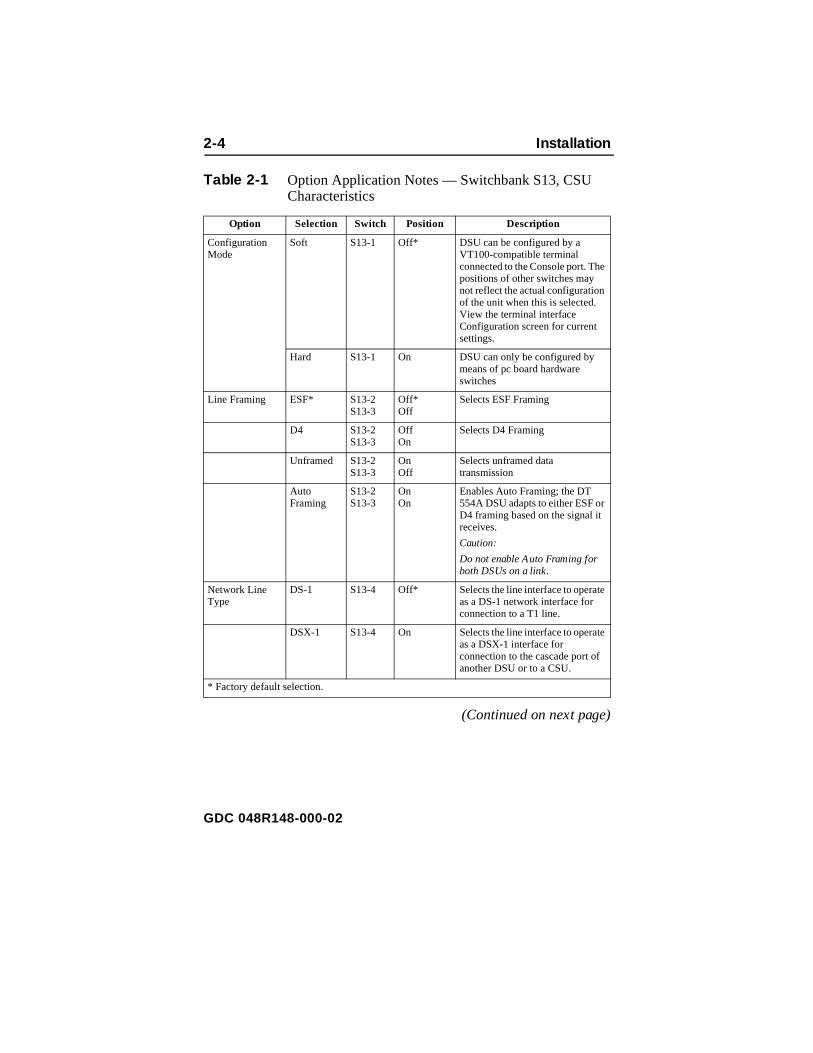
Table 2-1 Option Application Notes — Switchbank S13, CSU Characteristics
(Continued on next page)
Option Selection Switch Position Description
Configuration Mode
Soft S13-1 Off* DSU can be configured by a VT100-compatible terminal connected to the Console port. The positions of other switches may not reflect the actual configuration of the unit when this is selected. View the terminal interface Configuration screen for current settings.
Hard S13-1 On DSU can only be configured by means of pc board hardware switches
Line Framing ESF* S13-2S13-3
Off*Off
Selects ESF Framing
D4 S13-2S13-3
OffOn
Selects D4 Framing
Unframed S13-2S13-3
OnOff
Selects unframed data transmission
Auto Framing
S13-2S13-3
OnOn
Enables Auto Framing; the DT 554A DSU adapts to either ESF or D4 framing based on the signal it receives.
Caution:
Do not enable Auto Framing for both DSUs on a link.
Network Line Type
DS-1 S13-4 Off* Selects the line interface to operate as a DS-1 network interface for connection to a T1 line.
DSX-1 S13-4 On Selects the line interface to operate as a DSX-1 interface for connection to the cascade port of another DSU or to a CSU.
* Factory default selection.
GDC 048R148-000-02

Installation 2-5
Table 2-1 Option Application Notes — Switchbank S13, CSU Characteristics (Continued)
Option Selection Switch Position Description
DS-1 Line Build-Out (LBO)/ DSX-1Pre-equalization
LBO S13-5S13-6S13-7S13-8
All Off* = 0 dB
S13-5 On = -7.5 dB
S13-6 On = -15 dB
S13-7 On = -22.5 dB
S13-8 On = Auto LBO
These switches control LBO when a DS-1 line interface is selected at S13-4. Set all Off for 0 dB manual LBO. Set 5, 6, or 7 On for the spec-ified manual LBO. Set 8 On for au-tomatic LBO. Set only one switch On.
Caution:
Do not enable automatic LBO for both DSUs in a pair connected back-to-back. Do not enable auto-matic LBO when the DSU is con-nected to a DS1 Interface Connector (Smart Jack): use man-ual LBO with 0 dB attenuation.
Pre-equalization
S13-5S13-6S13-7S13-8
All Off* = 0-133 ft
S13-5 On = 133 -266 ft
S13-6 On = 266 -399 ft
S13-7 On = 399 -533 ft
S13-8 On = 533 -655 ft
These switches control Pre-equal-ization when a DSX-1 line inter-face is selected at S13-4.
Pre-equalization matches transmit-ter to network gain characteristics for DSX-1. Select the lowest value that equals or exceeds the distancebetween units.
* Factory default selection.
GDC 048R148-000-02

2-6 Installation
k
Table 2-2 Option Application Notes — Switchbank S14, NetworCharacteristics(Continued on next page)
Option Selection Switch Position Description
Network Coding
B8ZS* S14-1 Off* Selects Bipolar with 8 Zero Substi-tution (B8ZS) encoding for the net-work side
AMI S14-1 On Selects Alternate Mark Inversion (AMI) encoding for the network side.
The DSU enforces an 8 x (N+1) ones density requirement when AMI is selected in combination with framed N x 64k operation and con-secutive DS0s, or with unframed operation.
Network ESF Mode
ANSI T1.403*
S14-2 Off* Selects compliance with ANSI net-work performance messages (per Bellcore TR-TSY-000194), avail-able only with ESF framing.
TR 54016 S14-2 On Selects compliance with network maintenance messages per PUB 54016, available only with ESF framing.
Network TXTiming
Receive* S14-3S14-4
Off* or OnOff* On
The DSU recovers receive T1 clock from the network receive T1 data and uses it as the send timing source for T1 data output to the network.
Note:
Both settings provide the same result.
DTE S14-3S14-4
OffOn
The DSU translates the clock taken from the Ext Clk signal provided by the DTE and uses it as the send tim-ing source for T1 data output to the network.
Internal S14-3S14-4
OnOff
The DSU provides the send timing source for T1 data output to the net-work.
* Factory default selection.
GDC 048R148-000-02
Installation 2-7
k
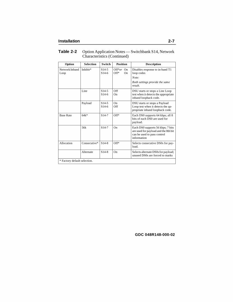
Table 2-2 Option Application Notes — Switchbank S14, NetworCharacteristics (Continued)
Option Selection Switch Position Description
Network Inband Loop
Inhibit* S14-5S14-6
Off* or OnOff* On
Disables response to in-band T1 loop codes
Note:
Both settings provide the same result.
Line S14-5S14-6
OffOn
DSU starts or stops a Line Loop test when it detects the appropriateinband loopback code.
Payload S14-5S14-6
OnOff
DSU starts or stops a Payload Loop test when it detects the ap-propriate inband loopback code.
Base Rate 64k* S14-7 Off* Each DS0 supports 64 kbps; all 8 bits of each DS0 are used for payload.
56k S14-7 On Each DS0 supports 56 kbps; 7 bitsare used for payload and the 8th bitcan be used to pass control information
Allocation Consecutive* S14-8 Off* Selects consecutive DS0s for pay-load.
Alternate S14-8 On Selects alternate DS0s for payload;unused DS0s are forced to marks
* Factory default selection.
GDC 048R148-000-02

2-8 Installation
Table 2-3 Option Application Notes — Switchbank S15, DTE Characteristics
Option Selection Switch Position Description
DTE CTS Forced ON* S15-1 Off* CTS forced On
Follow RTS S15-1 On CTS controlled by RTS
DTE DCD Forced ON* S15-2 Off* DCD forced On
Follow OOF
S15-2 On DCD Off when network signal is Out Of Frame
DTE DSR Forced ON* S15-3 Off* DSR forced ON
Follow LOS S15-3 On DSR Off when network Loss Of Signal is detected
DTE Receive Data
Normal* S15-4 Off* Channel Receive Data not inverted.
Invert S15-4 On Channel Receive Data inverted.
DTE Send Data Normal* S15-5 Off* Channel Transmit Data not inverted.
Invert S15-5 On Channel Transmit Data inverted.
DTE Split Timing
Disable* S15-6 Off* DSU uses selected Network TX Timing (S14-3&4) to clock T1 transmit data and channel send data
Enable S15-6 On DSU uses selected Network TX Timing (S14-3&4) to clock T1 transmit data, and uses the Ext Clk signal provided by DTE to clock channel send data
DTE Receive Clock
Normal* S15-7 Off* Channel Receive Clock not inverted.
Invert S15-7 On Channel Receive Clock inverted.
DTE Send Clock Normal* S15-8 Off* Channel Transmit Clock not inverted.
Invert S15-8 On Channel Transmit Clock inverted.
* Factory default selection.
GDC 048R148-000-02

Installation 2-9
Table 2-4 Option Application Notes — Switchbank S10, DTE Characteristics
Option Selection Switch Position Description
DTE Auto Clock Invert
Disable* S10-1 Off* Normal/Invert condition of DTE Receive and Send Clocks controlled by S15-7&8
Enable S10-1 On DSU monitors for data/clock mismatches in DTE data, and auto-matically toggles between Normal and Invert conditions to compensate for detected mismatch conditions. Overrides settings of S15-7&8
DTE Test Leads Disable* S10-2 Off* DTE Test Leads LL and RL disabled.
Enable S10-2 On DTE Test Leads LL and RL enabled.
DTE Test Pattern
2047* S10-3 Off* Selects 2047-bit Self-Test pattern for channel tests
511 S10-3 On Selects 511-bit Self-Test pattern for channel tests
LL Switch Mode Bilateral S10-4 Off* T1 Line Loop test loops full T1 back to network interface, and loops chan-nel back to DTE.
Channel Line Loop test loops channel back to DTE, and loops DS0s allocated to the channel back to network interface.
Unilateral S10-4 On T1 Line Loop test loops full T1 back to network interface.
Channel Line Loop test loops channel back to DTE.
* Factory default selection.
GDC 048R148-000-02

2-10 Installation
,
Table 2-5 Option Application Notes — Switchbanks S11 & S12DS0 AssignmentsOption Selection Switch Position Description
Starting DS0 1* — 24 S11-4S11-5S11-6S11-7S11-8
Default:
All Off = DS0 1
See Table 2-7 for other settings
Selects lowest numbered DS0 in the group that conveys channel data. The rest of the DS0s required to support the selected Channel Data Rate follow sequentially after the one selected here.
Number of DS0s
1 — 24* S12-4S12-5S12-6S12-7S12-8
Default:
All Off = 24 DS0s
See Table 2-6 for other settings
Selects how many DS0s are to be used for channel data. S14-7 determines rate of indi-vidual DS0s.
* Factory default selection.
GDC 048R148-000-02

Installation 2-11
Table 2-6 DTE Data Rate Selection — Switchbank S12
Rate* # of DS0s**
S12-4 S12-5 S12-6 S12-7 S12-8
1344/1536Default Setting
24 Off Off Off Off Off
56/64 1 Off Off Off Off On
112/128 2 Off Off Off On Off
168/192 3 (1/8) Off Off Off On On
224/256 4 Off Off On Off Off
280/320 5 Off Off On Off On
336/384 6 (1/4) Off Off On On Off
392/448 7 Off Off On On On
448/512 8 Off On Off Off Off
504/576 9 (3/8) Off On Off Off On
560/640 10 Off On Off On Off
616/704 11 Off On Off On On
672/768 12 (1/2) Off On On Off Off
728/832 13 Off On On Off On
784/896 14 Off On On On Off
840/960 15 (5/8) Off On On On On
896/1024 16 On Off Off Off Off
952/1088 17 On Off Off Off On
1008/1152 18 (3/4) On Off Off On Off
1064/1216 19 On Off Off On On
1120/1280 20 On Off On Off Off
1176/1344 21 (7/8) On Off On Off On
1232/1408 22 On Off On On Off
1288/1472 23 On Off On On On
1344/1536 24 On On Off Off Off
* Individual DS0 rate is controlled by option switch S14-7: On for 56 kbps, Off for 64 kbps.
**Figure in parentheses is the fraction of the full T1 bandwidth represented by the selectednumber of DS0s.
GDC 048R148-000-02

2-12 Installation
Table 2-7 DTE Starting DS0 Selections — Switchbank S11
Starting DS0 S11-4 S11-5 S11-6 S11-7 S11-8
1Default Setting
Off Off Off Off Off
1 Off Off Off Off On
2 Off Off Off On Off
3 Off Off Off On On
4 Off Off On Off Off
5 Off Off On Off On
6 Off Off On On Off
7 Off Off On On On
8 Off On Off Off Off
9 Off On Off Off On
10 Off On Off On Off
11 Off On Off On On
12 Off On On Off Off
13 Off On On Off On
14 Off On On On Off
15 Off On On On On
16 On Off Off Off Off
17 On Off Off Off On
18 On Off Off On Off
19 On Off Off On On
20 On Off On Off Off
21 On Off On Off On
22 On Off On On Off
23 On Off On On On
24 On On Off Off Off
GDC 048R148-000-02

Installation 2-13
rd d
on
d. ) re.
Connections
Figure 2-2 Back Panel Connectors
DTE Interface Port ConnectionThe DT 554A DSU provides one DTE interface port. In its standaconfiguration it is compatible with ITU-T V.35. It can also be orderewith the daughter card that makes the port EIA-530 compatible.
The DTE interface port is a 34-pin female (V.35) connector locatedthe rear panel. Refer to Table 1-1 for the appropriate interface cable.Refer to Appendix B for interface pin/signal assignments.
The optional EIA-530 interface card attaches to connectorsXA3P1, XA3P2, and XA3P3 on the main pc card. Figure 2-3 illustrates enable and disable positions for the daughter carWhen it is not present, shorting jumpers (P/N 208-011-716must be installed on the connectors as described in the figu
Network Interface Port – RJ48C
DTE Interface Port – ITU-T V.35 34-pin connector;
EIA-530 compatible when optional daughter card is installed
Console Port – for connection of VT100-compatible
terminal
AC Power Cord Connection
Network Console POWERBusiness Equipment
NOTE
GDC 048R148-000-02

2-14 Installation
Figure 2-3 EIA-530 Interface Daughter Card Installation
To bypass the EIA-530 inter-
face, install the plug-in card in
this position. Connections:
J2 to XA3P2J3 to XA3P3
J1, J4, and J5 are not used.
J1J2J3
J5J4 EIA-530 PLUG-IN CARDPART NO. 048P042-001
BY
PA
SS
J1J2 J3
J5 J5EIA-530 PLUG-IN CARDPART NO. 048P042-001
BY
PA
SS
Base card,
GDC048P102-001
rear edgeX
A3P
2X
A3P
3
XA3P1
This illustration shows the connectors on the plug-in card to help you position it. The connectors are actually on the underside, facing toward the base card, when you install the plug-in card.
There are jumpers on XA3P2 and XA3P3 when the optional plug-in card is not present.
To enable the EIA-530 inter-
face, install the plug-in card
in this position. Connections:
J2 to XA3P2J3 to XA3P3J1 t0 XA3P1
J5 and J4 are not used.
GDC 048R148-000-02

Installation 2-15
nel. to-e
nd
ted
d
Network ConnectionConnect the network (T1 line) to the DT 554A DSU as described below.
The network port interface is an RJ48C jack located on the rear paYou must use either GDC cable P/N 022H024-XXX (RJ48C plug-plug) or 022H021-XXX (RJ48C plug-to-terminal lugs) to connect thT1 line to the DSU. The plug-to-plug cable is labeled NETWORK aCSU to indicate where each end is used.
Pinouts for the network end of the network interface cables are lisbelow:
The Telco continuously monitors the T1 link and the equipment connected to it. Notify the Telco before connecting the DT 554A DSU to the network. The DT 554ADSU must remain continuously powered on and connecteto the T1 service. FCC Part 68 rules require the user to notify the service provider if the DSU is removed from service or turned off.
For Canadian installations only, a special cable is required for the network connection. Use GDC cable P/N 022H020(RJ48C to DB15F) to connect the network port to the T1 line.
Function Direction
027H242-X04022H024-XXX
Pin No.
022H025-XXX022H021-XXX
Wire color
Receive Data (Ring) To DSU 1 ORN/WHT
Receive Data (Tip) To DSU 2 WHT/ORN
Send Data (Ring) From DSU 4 BLU/WHT
Send Data (Tip) From DSU 5 WHT/BLU
Shield (Frame Gnd.) n/a 7 DRAIN
NOTE
NOTE
GDC 048R148-000-02

2-16 Installation
ions
d ac
trol. the ill
tial s is
d nel
Primary Power ConnectionAfter the DT 554A DSU has been installed and the above connecthave been made, connect primary power to the system.
Connect the ac power cord to the back panel and insert the moldethree-prong plug into a polarized outlet that provides the requiredpower.
The outlet that provides ac power should not be under switch conThe DT 554A DSU should be powered by the same ac source ascustomer equipment connected to it. Use of the same ac source wprevent large circulating currents caused by differences in groundpotential. If you cannot be sure that the customer equipment is powered by the same ac source as the DSU, verify that the potendifference between the grounding circuits of their respective outletless than 0.25 V rms.
Terminal ConnectionIf you are using a VT100-compatible terminal for configuration ancontrol of the DT 554A DSU, make the connection at the back paConsole port identified in Figure 2-2. The port is RS-561 compatible.Refer to Table 1-1 for the appropriate interface cable.
Note: The remaining leads are not used.
If you connect two DSUs back-to-back (a direct cable connection), automatic Line Build-Out must not be enabledfor both. It may be enabled in one of the units, if so desired.
a. This installation procedure must be followed for compliance with FCC Part 15, Subpart J, Class A requirements.
b. For Canadian installations only, a special cable is required for the network port connection. Use GDC cableP/N 022H020-XXX (RJ48C plug to 15-pin female) to connect the network port to the T1 line.
NOTE
GDC 048R148-000-02
Installation 2-17
Use of a terminal is optional. Configuration can be accomplished entirely by means of the hardware switches on the pc card.
GDC 048R148-000-02

3 Operation
. of of a ort.
its ions
der l ll E on
inal
by
e
ush
OverviewThis chapter provides instructions for operating the DT 554A DSUYou can control and monitor DSU functions in two ways: by meansthe switches and LED indicators on the front panel, and by meansVT100-compatible terminal connected to the back panel Console p
The front panel provides a group of monitoring functions through indicators and enables you to invoke a subset of the DSU test functthrough its four switches.
The terminal interface provided by the Console port supports a broarange of functions than does the front panel. Through the terminainterface you can alter the configuration of the DSU, invoke the furange of its diagnostic test functions, view the current status of DTinterface signals and unit alarm conditions, and display informationthe unit.
This chapter describes the use of front panel switches and the terminterface for accessing the DSU diagnostic functions. Chapter 4, Tests, describes in detail the actual test procedures that you can performthose means.
Controls and IndicatorsFigure 3-1 illustrates the DT 554A DSU front panel and explains thfunction of each control and indicator.
The four switches on the front panel are momentary action pushbuttons. One push on switch initiates its function, a second pterminates the function.
GDC 048R148-000-02

3-2 Operation
Figure 3-1 DT 554A Front Panel Controls and Indicators
General Data-Comm
DeskTop554A
ON SD RD OOF LOS BPV ALM TM T1 ST LL RL
ON (Green)Power On indicator
SD (Green)DTE Send Data indicator
RD (Green)DTE Receive Data indicator
LOS (Red)Network Loss of Signal indicator
OOF (Red)Network Out of Frame indicator
BPV (Red)Network Bipolar Violations indicator
ALM (Red)Alarm indicator
TM (Red)On while DSU is any Test Mode; flashes to indicateerrors when Self Test pattern generator/ checker isin use
T1 (Red LED & Switch)Selects tests between T1 (LED On) and Channel (LED Off). Selection must occur before a test is started; cannot be changed while a test is running.
ST (Red LED & Switch)Selects between Self Test patterngenerator/checker On (LED On) andOff (LED Off)
RL (Red LED & Switch)Controls Remote Loopback Test
LL (Red LED & Switch)Controls Line Loopback Test
GDC 048R148-000-02
Operation 3-3
ns. ays
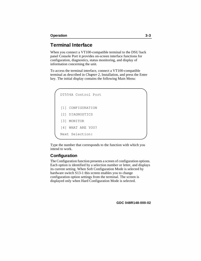
Terminal InterfaceWhen you connect a VT100-compatible terminal to the DSU backpanel Console Port it provides on-screen interface functions for configuration, diagnostics, status monitoring, and display of information concerning the unit.
To access the terminal interface, connect a VT100-compatible terminal as described in Chapter 2, Installation, and press the Enter key. The initial display contains the following Main Menu:
Type the number that corresponds to the function with which you intend to work.
ConfigurationThe Configuration function presents a screen of configuration optioEach option is identified by a selection number or letter, and displits current setting. When Soft Configuration Mode is selected by hardware switch S13-1 this screen enables you to change configuration option settings from the terminal. The screen is displayed only when Hard Configuration Mode is selected.
DT554A Control Port
[1] CONFIGURATION
[2] DIAGNOSTICS
[3] MONITOR
[4] WHAT ARE YOU?
Next Selection:
GDC 048R148-000-02

3-4 Operation
the
tothe
eld
Figure 3-2 Configuration Screen, with Default Settings
The procedure for changing configuration option settings involves following steps:
1. Type the selection number or letter of the option you intendchange. Highlighting appears on the current setting field for corresponding option.
2. Use the left and right arrow keys to toggle the highlighted fi
DT554A Configuration
[0]Return to Main Menu Unit is under SoftwareControl
[1]Network Framing: ESF[2]Network Coding: B8ZS[3]Network Line Type: DS-1[4]Network Line Buildout: Manual 0dB[5]Network ESF Mode: ANSI T1.403[6]Network Timing: Receive[7]Network Inband Loop: Inhibit
[8]DTE DS0 Format: N x 64 Kbps[9]DTE Starting DS0: 1[A]DTE Rate: 1536 Kbps (24 DS0s)[B]DTE Allocation: Consecutive[C]DTE CTS Control: Forced ON[D]DTE DCD Control: Forced ON[E]DTE DSR Control: Forced ON[F]DTE Invert Data: Normal[G]DTE Invert Timing: Normal[H]DTE Split Timing: Disable[I]DTE Test Leads: Disable
Next Selection:
GDC 048R148-000-02

Operation 3-5
nged
.
ble
t
s-
through its potential settings.
3. When the desired setting is displayed, press Enter. The chasetting goes into effect immediately.
4. Repeat steps 1 through 3 for each option you need to change
5. After you’ve made all required changes, type selection 0, Returnto Main Menu .
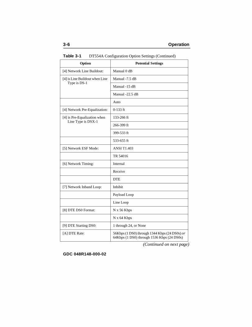
Table 3-1, which starts below, lists the configuration options that appear on the terminal interface display and all the settings availafor each. For more detailed descriptions of the individual option settings and their effects on operation of the DSU you can consulTables 2-1 through 2-5 in Chapter 2, Installation.
Table 3-1 DT554A Configuration Option Settings
(Continued on next page)
Option Potential Settings
[0] Return to Main Menu Unit is under Software Control*
Unit is under Hardware Control*
[1] Network Framing: ESF
D4
Unframed
Auto
[2] Network Coding: B8ZS
AMI
[3] Network Line Type: DS-1
DSX-1
* The setting of hardware switch S13-1 determines the Hard Mode/Soft Mode status that is displayed with the Return to Main Menu selection. This screen is diplay-only when the unit is in Hard Mode.
GDC 048R148-000-02
3-6 Operation
Table 3-1 DT554A Configuration Option Settings (Continued)
(Continued on next page)
Option Potential Settings
[4] Network Line Buildout: Manual 0 dB
[4] is Line Buildout when Line Type is DS-1
Manual -7.5 dB
Manual -15 dB
Manual -22.5 dB
Auto
[4] Network Pre-Equalization: 0-133 ft
[4] is Pre-Equalization when Line Type is DSX-1
133-266 ft
266-399 ft
399-533 ft
533-655 ft
[5] Network ESF Mode: ANSI T1.403
TR 54016
[6] Network Timing: Internal
Receive
DTE
[7] Network Inband Loop: Inhibit
Payload Loop
Line Loop
[8] DTE DS0 Format: N x 56 Kbps
N x 64 Kbps
[9] DTE Starting DS0: 1 through 24, or None
[A] DTE Rate: 56Kbps (1 DS0) through 1344 Kbps (24 DS0s) or 64Kbps (1 DS0) through 1536 Kbps (24 DS0s)
GDC 048R148-000-02
Operation 3-7
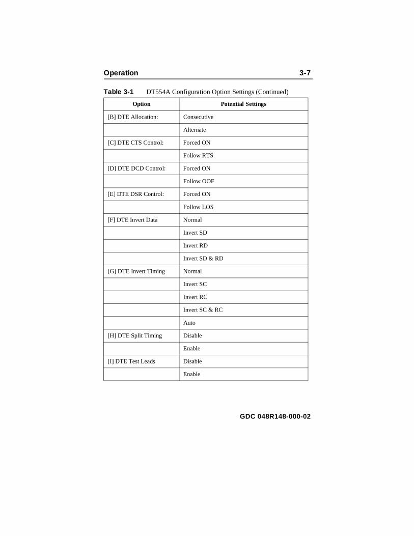
Table 3-1 DT554A Configuration Option Settings (Continued)
Option Potential Settings
[B] DTE Allocation: Consecutive
Alternate
[C] DTE CTS Control: Forced ON
Follow RTS
[D] DTE DCD Control: Forced ON
Follow OOF
[E] DTE DSR Control: Forced ON
Follow LOS
[F] DTE Invert Data Normal
Invert SD
Invert RD
Invert SD & RD
[G] DTE Invert Timing Normal
Invert SC
Invert RC
Invert SC & RC
Auto
[H] DTE Split Timing Disable
Enable
[I] DTE Test Leads Disable
Enable
GDC 048R148-000-02
3-8 Operation
one trol
e
nd he
DiagnosticsThe terminal interface DT554A Diagnostics function supports twoscreens: one by which you select and initiate tests on the DSU, andthat displays test results. The results screen also contains the confunction for ending a test.
You can perform a wider variety of tests from the terminal than aravailable by means of the DSU front panel switches. When you perform a test that employs the DSU Self Test pattern generator achecker, the results displayed on-screen are more detailed than terror indication provided by the front panel TM LED.
Figure 3-3 illustrates the Diagnostics selection screen, and Figure 3-4 illustrates the Diagnostics results screen. Detailed instructions forusing these screens appear in Chapter 4, Tests, together with descriptions of the diagnostic functions.
GDC 048R148-000-02

Operation 3-9
Figure 3-3 Diagnostics Selection Screen
DT554A Diagnostics
[0]Return to Main Menu
[1]Select LL Mode: Unilateral 1
[2]Start Network QRSS Self Test[3]Start Network Payload Loopback[4]Start Network Line Loopback[5]Start Network Local Test[6]Start Network Local Test with QRSS Self Test[7]Start Network Remote Test[8]Start Network Remote Test with QRSS Self Test
[9]Select DTE Self Test Pattern:2047 Pattern 2
[A]Start DTE Self Test[B]Start DTE Local Loopback[C]Start DTE Digital Loopback[D]Start DTE Remote Digital Loopback[E]Start DTE Remote Digital Loopback with SelfTest
Next Selection:
1 or Bilateral2 or 511 Pattern
GDC 048R148-000-02

3-10 Operation
of
of
Figure 3-4 Diagnostics Results Screen
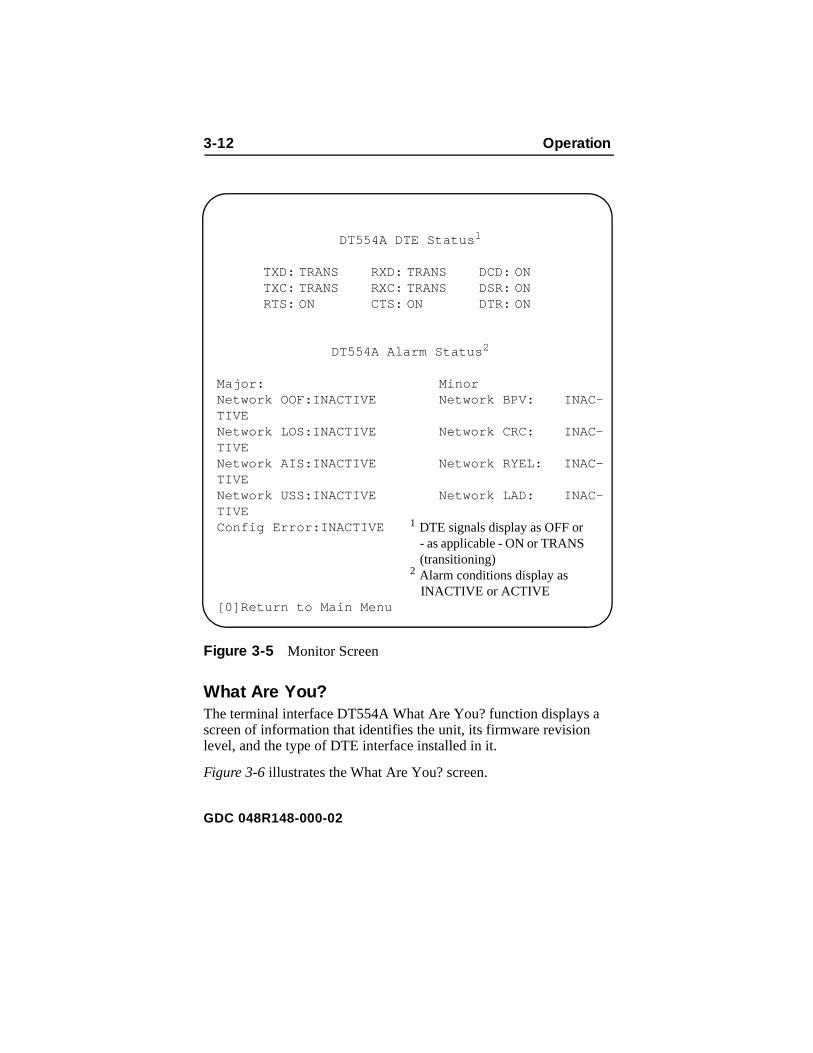
MonitorThe terminal interface DT554A Monitor function displays a screenstatus information concerning DTE interface signals and alarm conditions.
Figure 3-5 illustrates the Monitor screen.
The DTE Status portion of the screen displays the current status
DT554A Diagnostics
[0]Return to Main Menu
[1]Stop Test 1
[2]Inject Single Bit Error (ST only)[3]Reset Counters
Current Test: Network QRSS SelfTest 2
Test Status: Running 3
Test Duration: x minutes, y seconds
Bit Errors: 0000 e00 4
Next Selection: 1 displays "Restart Test" when Test Status is "Stopped"2 displays name of test selected from Diag-
nostic Selection screen; identifies Network Line Loopback and DTE Local Loopback tests as either Unilateral or Bilateral
3 or "Stopped"4 or "NO SYNC"; displays only while a Self Test is selected
GDC 048R148-000-02

Operation 3-11
On
,
the
nine DTE interface signals as OFF, ON, or TRANS. TRANS indicates that the signal is transitioning, as opposed to being in a prolongedor Off condition.
The Alarm Status portion of the screen displays the current statusINACTIVE or ACTIVE, of the nine alarm conditions that the DSU can report. Definitions of the alarm conditions appear in Appendix D, A larm Definitions.
When you are done viewing the Monitor screen, type 0 to return toMain Menu.
GDC 048R148-000-02
3-12 Operation
Figure 3-5 Monitor Screen
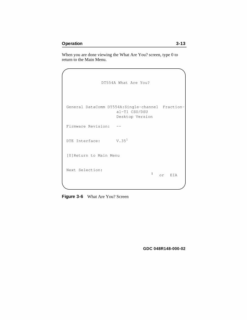
What Are You?The terminal interface DT554A What Are You? function displays ascreen of information that identifies the unit, its firmware revision level, and the type of DTE interface installed in it.
Figure 3-6 illustrates the What Are You? screen.
DT554A DTE Status 1
TXD: TRANS RXD: TRANS DCD: ONTXC: TRANS RXC: TRANS DSR: ONRTS: ON CTS: ON DTR: ON
DT554A Alarm Status 2
Major: MinorNetwork OOF:INACTIVE Network BPV: INAC-TIVENetwork LOS:INACTIVE Network CRC: INAC-TIVENetwork AIS:INACTIVE Network RYEL: INAC-TIVENetwork USS:INACTIVE Network LAD: INAC-TIVEConfig Error:INACTIVE
[0]Return to Main Menu
1 DTE signals display as OFF or - as applicable - ON or TRANS (transitioning)
2 Alarm conditions display as INACTIVE or ACTIVE
GDC 048R148-000-02
Operation 3-13
When you are done viewing the What Are You? screen, type 0 toreturn to the Main Menu.Figure 3-6 What Are You? Screen
DT554A What Are You?
General DataComm DT554A:Single-channel Fraction-al-T1 CSU/DSU Desktop Version
Firmware Revision: --
DTE Interface: V.35 1
[0]Return to Main Menu
Next Selection: 1 or EIA
GDC 048R148-000-02

3-14 Operation
GDC 048R148-000-02

4 Diagnostics
d ests
to
he
d
ote
nd that
The
ach
OverviewThis chapter describes the test functions of the DT 554A DSU anprovides instructions for their use. There are three ways to control tlocally:
• Terminal Interface Diagnostics Selection screen enables you command all DSU tests
• Front panel switches enable you to command all but three of tDSU tests
• DTE interface signals can command two tests – DTE Local anRemote Loopbacks.
The DSU can also be commanded remotely into tests that involvelooping the networks signal back to be checked for errors at the remsite. The remote site DSU transmits inband loop codes to commaremote loopbacks at the local unit. This chapter identifies the testscan be commanded remotely.
The structure of the chapter is based on the terminal interface Diagnostic Selection screen since it includes all the test functions. other two means of diagnostic control are limited to subsets.
The table on the following page lists the available tests and how ecan be commanded.
GDC 048R148-000-02

4-2 Diagnostics
ime, ther ns
ence
st
-
-
The local diagnostic functions work on a "first come, first served" basis: only one of the three means of control can be in effect at a tand a test that has begun cannot be overridden by either of the otwo types of control. While the terminal interface Diagnostic screeare open the DSU ignores the front panel switches and the DTE interface test leads.
Inband loop codes received from the remote site DSU take precedover local diagnostic functions. If a locally initiated test is running when a loop code is received, the DT 554A DSU terminates the teand performs the remote loopback.
Test: Can be commanded by –
Network QRSS Self Test Terminal Interface, Front Panel Switch ST (T1 indicator, controlled by T1 switch, must be On)
Network Payload Loopback Terminal Interface
Network Line Loopback Terminal Interface, Front Panel Switch LL (T1 indi-cator, controlled by T1 switch, must be On)
Network Local Test Terminal Interface
Network Local Test with QRSS Self Test
Terminal Interface
Network Remote Test Terminal Interface, Front Panel Switch RL (T1 indicator, controlled by T1 switch, must be On)
Network Remote Test with QRSS Self Test
Terminal Interface, Front Panel Switches RL and ST (T1 indicator, controlled by T1 switch, must be On)
DTE Self Test Terminal Interface, Front Panel Switch ST
DTE Local Loopback Terminal Interface, Front Panel Switch LL, DTE In-terface pin L
DTE Digital Loopback Terminal Interface
DTE Remote Digital Loopback
Terminal Interface, Front Panel Switch RL, DTE In-terface pin BB
DTE Remote Digital Loopback with Self Test
Terminal Interface, Front Panel Switches RL and ST
GDC 048R148-000-02

Diagnostics 4-3
Figure 4-1 Fault Isolation Procedure
Passor
Fail
Perform Network Local Test with
QRSS Self Test
PassFail Passor
Fail
Perform Network Remote Test, or Network Remote Test with Self Test, with
remote configured for Line Loopback
Local Equipment or Equipment-to-DSU
Connection Problem
Passor
Fail
Communication Line or Line-to-DSU Connection
Problem
Passor
Fail
Perform Network Local Test with QRSS Self Test
at remote DSU
Remote DSU or Equipment Problem
Passor
Fail
Perform Network Local Test at remote DSURemote DSU Problem
Passor
FailNo System Problem
Remote Equipment or Equipment-to-DSU
Connection Problem
Perform Network Remote Test, or Network Remote Test
with Self Test, with remote configured for Payload
Loopback
Fail
Fail
Fail
Fail
Fail
Pass
Pass
Pass
Pass
PassPerform Network Local TestLocal DSU Problem
Start
GDC 048R148-000-02

4-4 Diagnostics
n of d in
ve s of
Tests can be used at the time of installation or whenever operatiothe DSU must be checked. You can also use these tests as an aiisolating problems in the data communications system (refer to Figure 4-1, Fault-Isolation Procedure).
Terminal Interface Test ProcedureAll tests that you perform by means of the terminal interface involthe same basic procedure, which is described below. Descriptionthe individual tests appear on the following pages.
Figure 4-2 Diagnostics Selection Screen
DT554A Diagnostics
[0]Return to Main Menu
[1]Select LL Mode: Unilateral 1
[2]Start Network QRSS Self Test[3]Start Network Payload Loopback[4]Start Network Line Loopback[5]Start Network Local Test[6]Start Network Local Test with QRSS Self Test[7]Start Network Remote Test[8]Start Network Remote Test with QRSS Self Test
[9]Select DTE Self Test Pattern:2047 Pattern 2
[A]Start DTE Self Test[B]Start DTE Local Loopback[C]Start DTE Digital Loopback[D]Start DTE Remote Digital Loopback[E]Start DTE Remote Digital Loopback with Self Test
Next Selection:
1 or Bilateral2 or 511 Pattern
GDC 048R148-000-02

Diagnostics 4-5
re-formbothload
tics
to
-
of he unc-
u-
-t-
d
Employ the following procedure to initiate tests using the terminalinterface:
1. If the test is one that involves cooperation with an operator at amote site, contact that person and make arrangements to perthe test. Tests that must be initiated (and later terminated) at sites include end-to-end self tests, Line Loopbacks, and PayLoopbacks.
2. Select [2] DIAGNOSTICS from the terminal interface MainMenu. The DSU responds by displaying the DT554A DiagnosSelection screen, as shown in Figure 4-1.
3. Make any preliminary setups required for the test you intendperform. Two selections fall into this category:
[1] Select LL Mode must be set correctly if you are doing a Network Line Loopback or a DTE Local Loopback. When Unilateral is selected the function creates only one loopback: incoming data back onto the T1 line in the casethe network test, or transmit data back as receive data in tcase of the DTE test. When Bilateral is selected each test ftion loops data in both directions.
[9] Select DTE Self Test Pattern can be set to 2047 Pattern or 511 Pattern as needed for either ofthe two functions that involve DTE Self Test. This is particlarly important when doing an end-to-end self test.
To change the setting of either of these
A. Type the selection number or letter of the option you intend to change. Highlighting appears on the current seting field for the corresponding option.
B. Use the left and right arrow keys to toggle the highlightefield through its potential settings.
C. When the desired setting is displayed, press Enter.
GDC 048R148-000-02

4-6 Diagnostics
The4A
s
in
If
t
n
4. Type the selection number of the test you intend to perform. DSU responds by initiating the test and displaying the DT55Diagnostics results screen, as shown in Figure 4-3.
The Diagnostics Results screen displays four lines of information about the current test and a menu with four selections:
Current Test: identifies the test that is running, including Unilateral/Bilateral specification for Network Line Loopback orDTE Local Loopback.
Test Status: displays Running when the screen first appears; it displays Stopped when you select [1] Stop Test from the Results screen menu. The menu selection changes to [1] Restart Test when Stopped is displayed here.
Test Duration: displays how long the test has run.
Bit Errors: is displayed only when the Self Test function iin use; it normally displays the number of detected errors; it displays NO SYNC if no test pattern is being received during anend-to-end test.
In addition to [1] Stop/Restart Test , described together with Test Status above, and [0] Return to Main Menu the menu contains two selections:
[2] Inject Single Bit Error enables you to insert
A.The DSU must be optioned for Soft Configuration modeorder for you to perform LL Mode or DTE Self Test Pattern selection from the Diagnostics Selection screen.you attempt either selection while the DSU is in Hard Configuration mode, the screen displays a message thathe function is not available.
B.When the DSU is in Soft Configuration mode, changes youmake to the LL Mode or DTE Self Test Pattern selectiofrom the Diagnostics Selection screen also apply to howthose functions operate in response to the front panel switches.
NOTE
GDC 048R148-000-02

Diagnostics 4-7
n-
an intentional error as check on the error detector when runing a self test.[3] Reset Counters clears both the Bit Errors count and the Test Duration .
Figure 4-3 Diagnostics Results Screen
DT554A Diagnostics
[0]Return to Main Menu
[1]Stop Test 1
[2]Inject Single Bit Error (ST only)[3]Reset Counters
Current Test: Network QRSS SelfTest 2
Test Status: Running 3
Test Duration: x minutes, y seconds
Bit Errors: 0000 e00 4
Next Selection: 1 displays "Restart Test" when Test Status is "Stopped"2 displays name of test selected from Diag-
nostic Selection screen; identifies Network Line Loopback and DTE Local Loopback tests as either Unilateral or Bilateral
3 or "Stopped"4 or "NO SYNC"; displays only while a Self Test is selected
GDC 048R148-000-02

4-8 Diagnostics
tion he
st
rm
n or ater
U,
ons
tted.
n
en el. nly ted t
Network QRSS Self TestThe Network QRSS Self Test function provides test pattern generaand checking that involves the network interface while excluding tDTE interface. The pattern it provides is a quasi-random signal (QRSS).
The Network QRSS Self Test function appears three times in the terminal interface Diagnostics Selection menu: once by itself and twice in combination with loopback tests. The loopback-with-self tefunctions are discussed on later pages under their own headings.
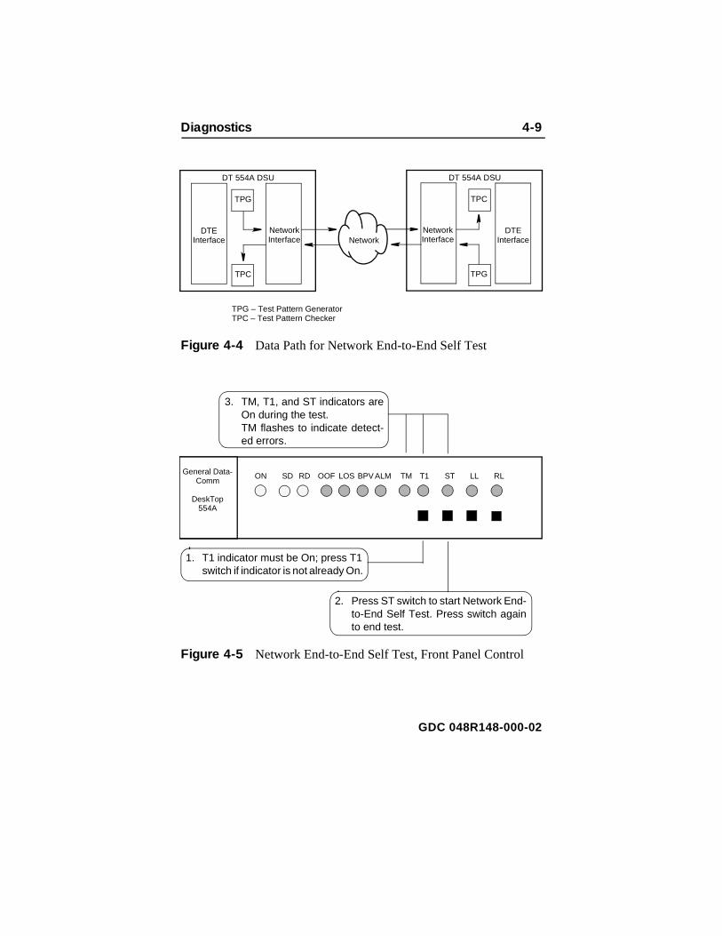
You can use the Network QRSS Self Test function by itself to perfoan End-to-End Self Test as illustrated in Figure 4-4. You can command the test by means of either the terminal interface screethe front panel switches. Use of the terminal interface provides gredetail in the test results. The test requires the cooperation of an operator at the remote site to initiate the function in the remote DSobserve the results, and terminate the function.
In the Network End-to-End Self Test, two DSUs transmit internallygenerated test patterns to each other for verification. Bipolar violatiare corrected during this test. Within each DSU, a Test Pattern Generator creates the test pattern, and a Test Pattern checker determines if the data it receives matches that which was transmiThe test checks both DSUs and the T1 link.
To initiate the test from the terminal interface Diagnostics Selectioscreen, select [2] Start Network QRSS Self Test .
Figure 4-5 shows the switches and indicators that are involved whyou command a Network End-to-End Self Test from the front panRemember that when you initiate the test from the front panel the odisplay of results is the TM indicator flashing in response to detecerrors. The terminal interface Diagnostics Results screen does nodisplay the results of tests initiated from the front panel.
GDC 048R148-000-02
Diagnostics 4-9
Figure 4-4 Data Path for Network End-to-End Self Test
Figure 4-5 Network End-to-End Self Test, Front Panel Control
Network
TPG – Test Pattern GeneratorTPC – Test Pattern Checker
DTE Interface
Network Interface
TPG
TPC
DTE Interface
Network Interface
TPC
TPG
DT 554A DSU DT 554A DSU
2. Press ST switch to start Network End-to-End Self Test. Press switch againto end test.
1. T1 indicator must be On; press T1 switch if indicator is not already On.
3. TM, T1, and ST indicators areOn during the test. TM flashes to indicate detect-ed errors.
General Data-Comm
DeskTop554A
ON SD RD OOF LOS BPV ALM TM T1 ST LL RL
GDC 048R148-000-02
4-10 Diagnostics
a
ack sed
ion
es
of
nt
itted
e
Network Payload LoopbackThe Network Payload Loopback function provides a data path fortest signal that is originated and checked at the remote site. The Payload Loopback, illustrated in Figure 4-6, loops back onto the T1 line only the receive DS0s that carry DTE channel data. The loopboccurs at a point within the DSU at which the data has already pasthrough most of the network interface circuitry.
You can command the loopback by means of either the terminal interface screen or the front panel switches:
• On the terminal interface Diagnostic Selection screen this functis selection [3] Start Network Payload Loopback . You can command the payload loopback from the terminal interface regardless of how DSU hardware configuration switchare set.
• The Network Payload Loopback function is performed as partthe DTE Local Loopback when DSU hardware configuration switch S10-4, LL Switch Mode, is set to Bilateral (Off). Figure 4-18 shows how to perform the DTE Local Loopback using the fropanel switches.
The payload loopback can also be initiated by a loop code transmto the local DSU from the remote site. Local DSU optioning determines whether it can be commanded into the loopback by thremote. For the DSU to accept the remote payload loop code, setswitches S14-5 & -6 to 5 On, 6 Off.
GDC 048R148-000-02

Diagnostics 4-11
st
ssed
ion
n s
to es r the to 5
Figure 4-6 Data Path for Network Payload Loopback
Network Line LoopbackThe Network Line Loopback function provides a data path for a tesignal that is originated and checked at the remote site. The Line Loopback, illustrated in Figure 4-7, loops back the entire T1 line. Theloopback occurs at a point within the DSU at which the data has pathrough only a minimum of the network interface circuitry.
You can command the loopback by means of either the terminal interface screen or the front panel switches:
• On the terminal interface Diagnostic Selection screen this functis selection [4] Start Network Line Loopback .
• Figure 4-8 shows the switches and indicators that are involvedwhen you command a Network Line Loopback from the front panel. The DSU also establishes a DTE Local Loopback wheDSU hardware configuration switch S10-4, LL Switch Mode, iset to Bilateral (Off).
The line loopback can also be initiated by a loop code transmittedthe local DSU from the remote site. Local DSU optioning determinwhether it can be commanded into the loopback by the remote. FoDSU to accept the remote line loop code, set switches S14-5 & -6 Off, 6 On.
NetworkDTE
InterfaceNetwork Interface
DT 554A DSU
DTE or other signal source
Network Payload Loopback can be commanded from front panel by running DTE Local Loopback with DSU optioned for bilateral loopbacks (switch S10-4).
Network Payload Loopback
GDC 048R148-000-02

4-12 Diagnostics
Figure 4-7 Data Path for Network Line Loopback
Figure 4-8 Network Line Loopback, Front Panel Control
NetworkDTE
InterfaceNetwork Interface
DT 554A DSU
DTE or other signal source
When DSU is optioned for bilateral loopbacks (switch S10-4) a DTE Local Loopback is also initiated when Network Line Loopback is commanded.
Network Line Loopback
2. Press LL switch to start Network LineLoopback. Press switch again to endtest.
1. T1 indicator must be On; press T1 switch if indicator is not already On.
3. TM, T1, and LL indicators areOn during the test.
General Data-Comm
DeskTop554A
ON SD RD OOF LOS BPVALM TM T1 ST LL RL
GDC 048R148-000-02

Diagnostics 4-13
e by an
he
lect
e
back ed an
Network Local TestThe data path for the Network Local Test is illustrated in Figure 4-9. This test can only be commanded from the terminal interface Diagnostics Selection screen.
The DSU loops the transmit signal back to the receive path at thenetwork interface. While the loop is in effect the DSU transmits anAlarm Indication Signal (all ones) on the T1 line. The DTE interfacremains active so that a test signal can be generated and checkedexternal device.
Local Test checks the local DSU, including the channel interface,isolated from the T1 line. Error detection and reporting is entirely tresponsibility of the external device that supplies the test signal.
To initiate the loopback from the Diagnostics Selection screen, se[5] Start Network Local Test .
Figure 4-9 Data Path for Network Local Test
Network Local Test with QRSS Self TestThe data path for the Network Local Test with QRSS Self Test is illustrated in Figure 4-10. This test can only be commanded from thterminal interface Diagnostics Selection screen.
The DSU generates a QRSS test pattern, loops the transmit signalto the receive path at the network interface, and checks the returntest pattern for errors. While the loop is in effect the DSU transmitsAlarm Indication Signal (all ones) on the T1 line. The DSU is electronically disconnected from its DTE during the test.
DT 554A DSU
DTE Interface
Network Interface
DTE or other signal source
GDC 048R148-000-02
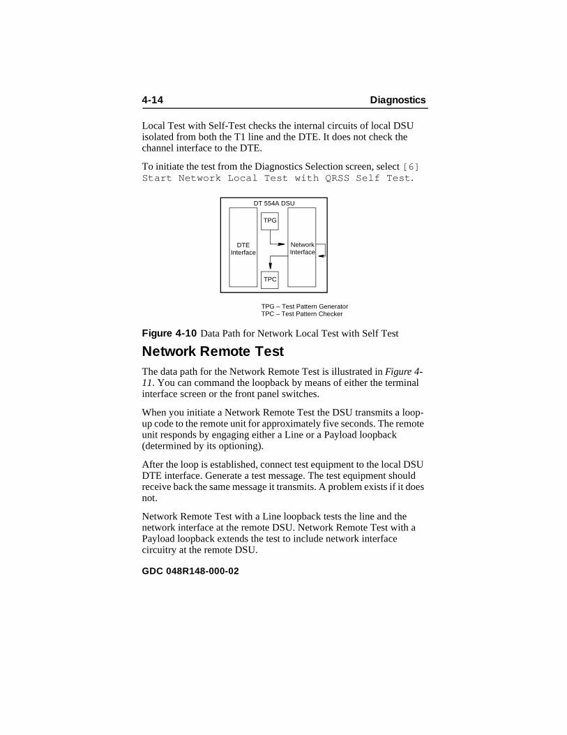
4-14 Diagnostics
al
op-ote
SU uld oes
a
Local Test with Self-Test checks the internal circuits of local DSUisolated from both the T1 line and the DTE. It does not check the channel interface to the DTE.
To initiate the test from the Diagnostics Selection screen, select [6] Start Network Local Test with QRSS Self Test .
Figure 4-10 Data Path for Network Local Test with Self Test
Network Remote TestThe data path for the Network Remote Test is illustrated in Figure 4-11. You can command the loopback by means of either the termininterface screen or the front panel switches.
When you initiate a Network Remote Test the DSU transmits a loup code to the remote unit for approximately five seconds. The remunit responds by engaging either a Line or a Payload loopback (determined by its optioning).
After the loop is established, connect test equipment to the local DDTE interface. Generate a test message. The test equipment shoreceive back the same message it transmits. A problem exists if it dnot.
Network Remote Test with a Line loopback tests the line and the network interface at the remote DSU. Network Remote Test with Payload loopback extends the test to include network interface circuitry at the remote DSU.
TPG – Test Pattern GeneratorTPC – Test Pattern Checker
DT 554A DSU
DTE Interface
Network Interface
TPG
TPC
GDC 048R148-000-02

Diagnostics 4-15
n
en
To initiate the test from the terminal interface Diagnostics Selectioscreen, select [7] Start Network Remote Test .
Figure 4-12 shows the switches and indicators that are involved whyou command a Network Remote Test from the front panel.
Figure 4-11 Data Path for Network Remote Test
Figure 4-12 Network Remote Test, Front Panel Control
Network
DT 554A DSU
DTE Interface
Network Interface
DTE Interface
Network Interface
Line Loopback or Payload Loopback as selected by remote DSU configuration
DTE or other signal source
DT 554A DSU
2. Press RL switch to start NetworkRemote Test. Press switch againto end test.
1. T1 indicator must be On; press T1 switch if indicator is not already On.
3. TM, T1, and RL indicators areOn during the test.
General Data-Comm
DeskTop554A
ON SD RD OOF LOS BPVALM TM T1 ST LL RL
GDC 048R148-000-02

4-16 Diagnostics
is s
op-ote
ttern ked ted
a
n
en the
Network Remote Test with QRSS Self TestThe data path for the Network Remote Test with QRSS Self Test illustrated in Figure 4-13. You can command the loopback by meanof either the terminal interface screen or the front panel switches.
When you initiate a Network Remote Test the DSU transmits a loup code to the remote unit for approximately five seconds. The remunit responds by engaging either a Line or a Payload loopback (determined by its optioning).
When the loop is established the DSU generates a QRSS test paand transmits it to the remote DSU which loops it back to be checfor errors at the local DSU. The DSUs are electronically disconnecfrom their DTEs during the test.
Network Remote Test with a Line loopback tests the line and the network interface at the remote DSU. Network Remote Test with Payload loopback extends the test to include network interface circuitry at the remote DSU.
To initiate the test from the terminal interface Diagnostics Selectioscreen, select [8] Start Network Remote Test with QRSS Self Test .
Figure 4-14 shows the switches and indicators that are involved whyou command a Network Remote Test with QRSS Self Test from front panel.
Figure 4-13 Data Path for Network Remote Test with Self TestFigure 4-13 Data Path for Network Remote Test with Self Test
Network
TPG – Test Pattern GeneratorTPC – Test Pattern Checker
DT 554A DSU
DTE Interface
Network Interface
TPG
TPC
DTE Interface
Network Interface
Line Loopback or Payload Loopback as selected by remote DSU configuration
DT 554A DSU
GDC 048R148-000-02

Diagnostics 4-17
able tern
he nce k .
d-
Figure 4-14 Network Remote Test with Self Test, Front Panel Control
DTE Self TestThe DTE Self Test function provides test pattern generation and checking that involves the DTE interface. The test pattern is selectto be either a 2047-bit or a 511-bit pattern. You can select the patby means of hardware switch S10-3 or by means of the terminal interface DT554A Diagnostics Selection screen, [9] Select DTE Self Test Pattern .
The DTE Self Test function can be initiated from two selections in tterminal interface Diagnostics Selection menu: once by itself and oin combination with a loopback test. The Remote Digital Loopbacwith Self Test is discussed on a later page under its own heading
You can use the DTE Self Test function by itself to perform an Ento-End Self Test as illustrated in Figure 4-15. You can command the
2. Press RL and ST switches to startNetwork Remote Test with Self Test.Press switches again to end test.
1. T1 indicator must be On; press T1 switch if indicator is not already On.
3. TM, T1, ST, and RL indicatorsare On during the test. TM flashes to indicate detect-ed errors.
General Data-Comm
DeskTop554A
ON SD RD OOF LOS BPVALM TM T1 ST LL RL
GDC 048R148-000-02

4-18 Diagnostics
anel he e
ons
tted.
n
en
nly ted t
test by means of either the terminal interface screen or the front pswitches. Use of the terminal interface provides greater detail in ttest results. The test requires the cooperation of an operator at thremote site to initiate the function in the remote DSU, observe theresults, and terminate the function.
In the DTE End-to-End Self Test, two DSUs transmit internally generated test patterns to each other for verification. Bipolar violatiare corrected during this test. Within each DSU, a Test Pattern Generator creates the test pattern, and a Test Pattern checker determines if the data it receives matches that which was transmiThe test checks both DSUs and the T1 link.
To initiate the test from the terminal interface Diagnostics Selectioscreen, select [A] Start DTE Self Test .
Figure 4-16 shows the switches and indicators that are involved whyou command a DTE End-to-End Self Test from the front panel. Remember that when you initiate the test from the front panel the odisplay of results is the TM indicator flashing in response to detecerrors. The terminal interface Diagnostics Results screen does nodisplay the results of tests initiated from the front panel.
Figure 4-15 Data Path for DTE End-to-End Self Test
Network
DT 554A DSU
DTE Interface
TPG – Test Pattern GeneratorTPC – Test Pattern Checker
TPG
TPC
Network Interface
TPC
TPG
DT 554A DSU
DTE Interface
Network Interface
GDC 048R148-000-02

Diagnostics 4-19
st nal
U lity
lect
en an TE
Figure 4-16 DTE End-to-End Self Test, Front Panel Control
DTE Local LoopbackThe data path for the DTE Local Loopback is illustrated in Figure 4-17. The DSU loops the transmit signal back to the receive path jubeyond the DTE interface, which remains active so that a test sigcan be generated and checked by an external device.
DTE Local Loopback checks the DTE interface and the DTE-to-DSconnection. Error detection and reporting is entirely the responsibiof the external device that supplies the test signal.
To initiate the loopback from the Diagnostics Selection screen, se[B] Start DTE Local Loopback .
Figure 4-18 shows the switches and indicators that are involved whyou command a DTE Local Loopback from the front panel. You calso command the test by means of DTE interface pin L when the DTest Leads configuration option is enabled (switch S10-2 On).
2. Press ST switch to start DTE End-to-End Self Test. Press switch again toend test.
1. T1 indicator must be Off; press T1 switch if indicator is On.
3. TM and ST indicators are Onduring the test. TM flashes to indicate detect-ed errors.
General Data-Comm
DeskTop554A
ON SD RD OOF LOS BPV ALM TM T1 ST LL RL
GDC 048R148-000-02

4-20 Diagnostics
Figure 4-17 Data Path for DTE Local Loopback
Figure 4-18 DTE Local Loopback, Front Panel Control
NetworkDTE
InterfaceNetwork Interface
DT 554A DSU
DTE or other signal source
When DSU is optioned for bilateral loopbacks (switch S10-4) a Network Payload Loopback is also initiated when DTE Local Loopback is commanded.
DTE Local Loopback
2. Press LL switch to start DTE LocalLoopback Test. Press switch again toend test.
1. T1 indicator must be Off; press T1 switch if indicator is On.
3. TM and LL indicators are Onduring the test.
General Data-Comm
DeskTop554A
ON SD RD OOF LOS BPV ALM TM T1 ST LL RL
GDC 048R148-000-02

Diagnostics 4-21
t al
in nal
its
is ce. k the
the
DTE Digital LoopbackThe DTE Digital Loopback function provides a data path for a tessignal that is originated and checked at the remote site. The DigitLoopback, illustrated in Figure 4-19, loops receive data back throughthe transmit portion of the DTE interface.
You can command the loopback only by means of the terminal interface DT554A Diagnostics Selection screen.
To initiate the loopback from the terminal interface DT554A Diagnostics Selection screen, select [C] Start DTE Digital Loopback .
Figure 4-19 Data Path for DTE Digital Loopback
DTE Remote Digital LoopbackThe data path for the DTE Remote Digital Loopback is illustrated Figure 4-20. You can command the loopback by means of the termiinterface screen, the front panel switches, or a signal on the DTEinterface.
When you initiate a DTE Remote Digital Loopback the DSU transma PN127 code to the remote unit. The remote unit responds by establishing a digital loopback toward the local DSU. After the loopestablished, connect test equipment to the local DSU DTE interfaGenerate a test message. The test equipment should receive bacsame message it transmits. A problem exists if it does not. DTE Remote Digital Loopback tests the local DSU, the line, and most ofremote DSU.
NetworkDTE
InterfaceNetwork Interface
DT 554A DSU
GDC 048R148-000-02

4-22 Diagnostics
n
en el.
B
To initiate the test from the terminal interface Diagnostics Selectioscreen, select [D] Start DTE Remote Digital Loopback .
Figure 4-21 shows the switches and indicators that are involved whyou command a DTE Remote Digital Loopback from the front pan
You can also command the test by means of DTE interface pin Bwhen the DTE Test Leads configuration option is enabled (switchS10-2 On).
Figure 4-20 Data Path for DTE Remote Digital Loopback
Figure 4-21 DTE Remote Digital Loopback, Front Panel Control
Network
DT 554A DSU
DTE Interface
Network
Interface
DTE
Interface
Network Interface
DT 554A DSU
DTE or other signal source
2. Press RL switch to start DTE RemoteDigital Loopback Test. Press switchagain to end test.
1. T1 indicator must be Off; press T1 switch if indicator is On.
3. TM and RL indicators are Onduring the test.
General Data-Comm
DeskTop554A
ON SD RD OOF LOS BPVALM TM T1 ST LL RL
GDC 048R148-000-02

Diagnostics 4-23
t is s
he .
t be
n
en
lf
DTE Remote Digital Loopback with Self TestThe data path for the DTE Remote Digital Loopback with Self Tesillustrated in Figure 4-22. You can command the loopback by meanof the terminal interface screen or the front panel switches.
When you initiate a DTE Remote Digital Loopback with Self Test tDSU transmits a PN127 code to the remote unit. The remote unitresponds by establishing a digital loopback toward the local DSU
When the loop is established the DSU generates the selected tespattern and transmits it to the remote DSU which loops it back to checked for errors at the local DSU. The DSUs are electronically disconnected from their DTEs during the test.
To initiate the test from the terminal interface Diagnostics Selectioscreen, select [E] Start DTE Remote Digital Loopback with Self Test .
Figure 4-23 shows the switches and indicators that are involved whyou command a DTE Remote Digital Loopback with Self Test fromthe front panel.
Figure 4-22 Data Path for DTE Remote Digital Loopback with SeTest
Network
DT 554A DSU
DTE
Interface
Network Interface
TPG – Test Pattern GeneratorTPC – Test Pattern Checker
TPG
TPC
DTE Interface
Network
Interface
DT 554A DSU
GDC 048R148-000-02
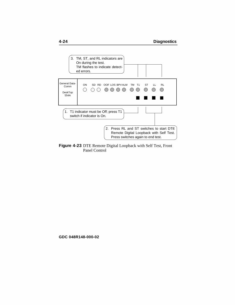
4-24 Diagnostics
Figure 4-23 DTE Remote Digital Loopback with Self Test, Front Panel Control
2. Press RL and ST switches to start DTERemote Digital Loopback with Self Test.Press switches again to end test.
1. T1 indicator must be Off; press T1 switch if indicator is On.
3. TM, ST, and RL indicators areOn during the test. TM flashes to indicate detect-ed errors.
General Data-Comm
DeskTop554A
ON SD RD OOF LOS BPVALM TM T1 ST LL RL
GDC 048R148-000-02
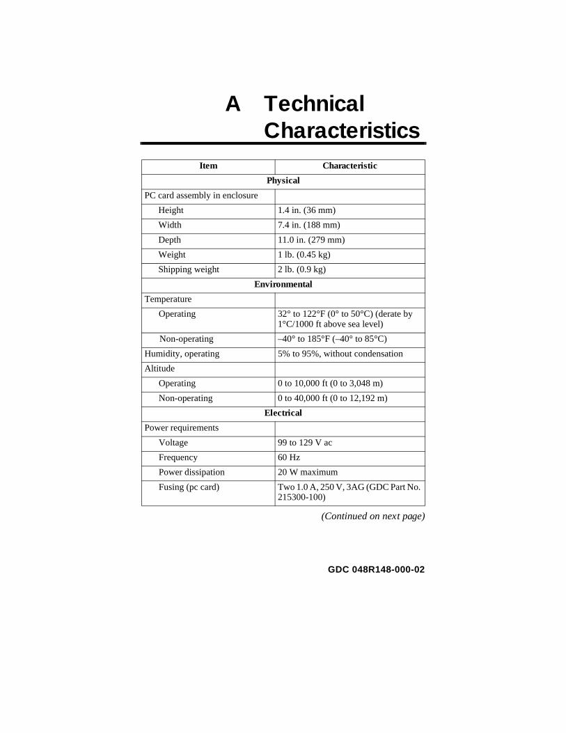
A TechnicalCharacteristics
(Continued on next page)
Item Characteristic
Physical
PC card assembly in enclosure
Height 1.4 in. (36 mm)
Width 7.4 in. (188 mm)
Depth 11.0 in. (279 mm)
Weight 1 lb. (0.45 kg)
Shipping weight 2 lb. (0.9 kg)
Environmental
Temperature
Operating 32° to 122°F (0° to 50°C) (derate by 1°C/1000 ft above sea level)
Non-operating –40° to 185°F (–40° to 85°C)
Humidity, operating 5% to 95%, without condensation
Altitude
Operating 0 to 10,000 ft (0 to 3,048 m)
Non-operating 0 to 40,000 ft (0 to 12,192 m)
Electrical
Power requirements
Voltage 99 to 129 V ac
Frequency 60 Hz
Power dissipation 20 W maximum
Fusing (pc card) Two 1.0 A, 250 V, 3AG (GDC Part No. 215300-100)
GDC 048R148-000-02

A-2 Technical Characteristics
-
(Continued on next page)
Item Characteristic
Electrical (Continued)
Data rates N x 64 kbps or N x 56 kbps (N = 1 to 24); maximum aggregate (payload) rate of 1,536,000 bps (1,544,000 bps in unframed mode)
Communication line T1 digital carrier (non-loaded, stag-gered-twist ABAM, PIC, or pulp-insu-lated exchange-type cable, 19 to 26 gauge)
Line impedance 100ΩNetwork port physical interface RJ48C modular jack
Network port physical interface RJ48C modular jack
Network transmitter
Frequency 1,544,000 bps ± 50 bps
Pulse amplitude — with surge protection
2.40 to 3.60 V at 60°F — may vary over a cycle of 60 Hz current.
Unbalance in height of adjacent negative and positive pulses
200 mV (maximum)
Width of output pulse (half amplitude)
324 nsec ± 45 nsec
Unbalance in width of positive and negative pulses
20 nsec (maximum)
Time between two consecutive pulses of opposite polarity
648 nsec ± 15 nsec (measured at half amplitude point of leading edges)
Maximum rise or falling time 100 nsec
Overshoot at trailing edge of pulse
10% to 30% of pulse amplitude
Line Build-Out 0, 7.5, 15, or 22.5 dB (selectable or automatic) at 772 kHz
GDC 048R148-000-02
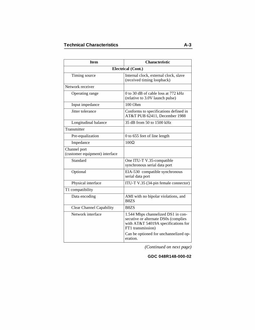
Technical Characteristics A-3
-
(Continued on next page)
Item Characteristic
Electrical (Cont.)
Timing source Internal clock, external clock, slave (received timing loopback)
Network receiver
Operating range 0 to 30 dB of cable loss at 772 kHz (relative to 3.0V launch pulse)
Input impedance 100 Ohm
Jitter tolerance Conforms to specifications defined in AT&T PUB 62411, December 1988
Longitudinal balance 35 dB from 50 to 1500 kHz
Transmitter
Pre-equalization 0 to 655 feet of line length
Impedance 100ΩChannel port (customer equipment) interface
Standard One ITU-T V.35-compatible synchronous serial data port
Optional EIA-530 compatible synchronous serial data port
Physical interface ITU-T V.35 (34-pin female connector)
T1 compatibility
Data encoding AMI with no bipolar violations, and B8ZS
Clear Channel Capability B8ZS
Network interface 1.544 Mbps channelized DS1 in con-secutive or alternate DS0s (complies with AT&T 54019A specifications for FT1 transmission)
Can be optioned for unchannelized operation.
GDC 048R148-000-02

A-4 Technical Characteristics
Item Characteristic
Electrical (Cont.)
Consecutive zeros enforcement
8 x (N+1) when configured for AMI, consecutive, N x 64, framed; or AMI, unframed
Keep Alive signal Type 1 (consecutive, framed ones fill-ing the unused bandwidth)
Framing format D4 Superframe, AT&T 54016 Extended Superframe (ESF),ANSI T1.403 ESF with automatic frame format, unframed option
Alarms and status conditionsOut of Frame (OOF), Alarm Indication Signal (AIS or Blue alarm), Loss of Signal (LOS)
Diagnostics Network Self-Test; Network Line Loop; Network Payload Loop; Network Local Test, with Self-Test; Network Remote Test, with Self-Test; DTE Self-Test;DTE Local Loop; DTE Digital Loop; DTE Remote Digital Loop, with Self-Test.
Front panel test switch
EIA test leads for LL, RL
GDC 048R148-000-02

B Interface Signals
Table B-1 ITU-T V.35 (Standard Interface)
34-PinPin No. Function Direction
A Frame Ground, AA n/a
P Send Data (a), BA To DSU
S Send Data (b), BA To DSU
R Rcv Data (a), BB From DSU
T Rcv Data (b), BB From DSU
C RTS, CA To DSU
D CTS, CB From DSU
E DSR, CC From DSU
B Sig Gnd, AB n/a
F DCD, CF From DSU
L LL To DSU
U Ext Clk (a), DA To DSU
W Ext Clk (b), DA To DSU
V Rcv Clk (a), DD From DSU
X Rcv Clk (b), DD From DSU
Y Tx Clk (a), DB From DSU
AA Tx Clk (b), DB From DSU
H DTR, CD To DSU
BB RDL, RL To DSU
K Test Mode, TM From DSU
GDC 048R148-000-02

B-2 Interface Signals
e from pter
Table B-2 EIA-530 (Optional Interface)*
* The optional EIA-530 interface for a DT 554A DSU is implemented through th34-pin female business equipment connector on the back panel. Conversion that connector to a standard DB25 female connector for EIA-530 requires AdaCable GDC Part No. 027H901-001. This table lists pinouts for both types of connector.
34-Pin Pin No. DB25 Pin No. Function Direction
A 1 Frame Ground, AA n/a
P 2 Send Data (a), BA To DSU
S 14 Send Data (b), BA To DSU
R 3 Rcv Data (a), BB From DSU
T 16 Rcv Data (b), BB From DSU
C 4 RTS (a), CA To DSU
Y 19 RTS (b), CA To DSU
D 5 CTS (a), CB From DSU
V 13 CTS (b), CB From DSU
E 6 DSR (a), CC From DSU
J 22 DSR (b), CC From DSU
B 7 Sig Gnd, AB n/a DSU
F 8 DCD (a), CF From DSU
HH 10 DCD (b), CF From DSU
X 17 Rcv Clk (a), DD From DSU
MM 9 Rcv Clk (b), DD From DSU
W 24 Ext Clk (a), DA To DSU
CC 11 Ext Clk (b), DA To DSU
AA 15 Tx Clk (a), DB From DSU
U 12 Tx Clk (b), DB From DSU
H 20 DTR (a), CD To DSU
Z 23 DTR (b), CD To DSU
BB 21 RDL, RL To DSU
K 25 Test Mode, TM From DSU
L 18 LL To DSU
GDC 048R148-000-02

C Timing Options
ally s of
the n
ions
e
ly the nce ly
is ock er e
OverviewThe flexibility and complexity of the timing options for the DT 554ADSU require explanations that are more detailed than those normprovided. This appendix therefore describes details and applicationthe DT 554A DSU timing options:
• Receive Timing
• Internal Timing
• DTE Timing
• DTE Split Timing
Each description is accompanied by an illustration that shows howtiming clock is distributed throughout the network. The timing optiodescriptions are followed by some representative network applicatthat show how to apply the timing options in a variety of network configurations.
Timing Option DescriptionsIn synchronous networks, all device transmitters and receivers arusually referenced to a single master timing source. This timing source, or clock, is frequently provided by the network and is highaccurate and stable. The DSU recovers the embedded clock fromdata stream and uses it to synchronize its own internal timing refereto the master clock. This allows the DSU to extract the data reliaband further to distribute timing to other devices connected to it. (Timing is embedded in the data stream on the network port, but provided on a separate lead in the DTE interface.) The network clis the preferred timing source, but the DT 554A DSU supports othtiming options as well, for use in applications where timing from thnetwork clock is either not available or not applicable.
GDC 048R148-000-02

C-2 Timing Options
, ork
ed en ay
nd
into
ce
rk,
red
U A
r
e
r, s f a r
The default timing option for the DT 554A DSU is Receive Timingused when the network provides the timing source. When the netwdoes not provide the timing source, one DT 554A DSU must use Internal Timing (or DTE Timing when customer equipment connectto it provides timing) and the others must use Receive Timing. Whthe network and the customer equipment both provide timing, you mneed to use DTE Split Timing, a combination of Receive Timing aDTE Timing.
One thing is common to all DT 554A DSU timing options: the DSUuses the clock it recovers from network receive data to clock data the receive buffer and to provide the channel receive clock signal for the channel. What differs is the source of the master clock referenand the source of the channel transmit clock signals, as shown in Table C-1:
• With Receive Timing, the master clock comes from the netwoand channel transmit clock signals are derived from the clock recovered from the network receive data.
• With Internal Timing, the DSU provides the master clock, but channel transmit clock signals are still derived from the recoveclock.
• With DTE Timing, the customer equipment connected to the DSprovides its own transmit clock signal, from which the DT 554
Several techniques exist for providing timing to the customeequipment: smooth clock and variations of gapped clock. With a smooth or continuous clock, the type employed by thDT 554A DSU, every clock pulse is the same length and occurs at the same interval. With a gapped clock, howevepulses are intentionally omitted. Customer equipment that iexpecting a smooth clock may not function properly with agapped clock. It may interpret the missing pulses as loss otiming. A gapped clock, moreover, may never be used as timing reference or to convey network timing. On the othehand, equipment that can tolerate a gapped clock will probably work well with a smooth clock, making the smoothclock technique more universally acceptable.
NOTE
GDC 048R148-000-02

Timing Options C-3
the
he
t, 4 tes
hen
4A ata it
DSU derives a master clock. For this method, the DTE must bemaster source of timing.
• With DTE Split Timing, the customer equipment connected to tDSU provides its own transmit clock signal (like DTE Timing),but the network provides the master clock for the rest of the network (like Receive Timing).
The data rate on the network port is 1.544 Mbps. On the DTE porhowever, the data rate may be from 56 Kbps to 1.536 Mbps (1.54Mbps when using unframed mode). The DT 554A DSU compensafor the difference in data rates by translating the clock frequency wpassing it from one port to another.
Table C-1 Timing Option Reference
Receive TimingWith Receive Timing, illustrated in Figure C-1, the network (or a device at the remote end) provides the timing source (1). The DT 55DSU recovers the receive T1 clock from the network receive T1 dand uses it both to clock T1 data into the receive buffer (2) and toprovide the send timing source for T1 data output from the transm
All timing options that include split timing require each timing source to be traceable to the same Stratum 1 clock.
Master Clock SourceCh. Trans.
Clock Source
Timing Option Net. 554 DTE Net. DTE
Receive Timing Ð Ð
Internal Timing Ð Ð
DTE Timing Ð Ð
DTE Split Timing Ð Ð
NOTE
GDC 048R148-000-02
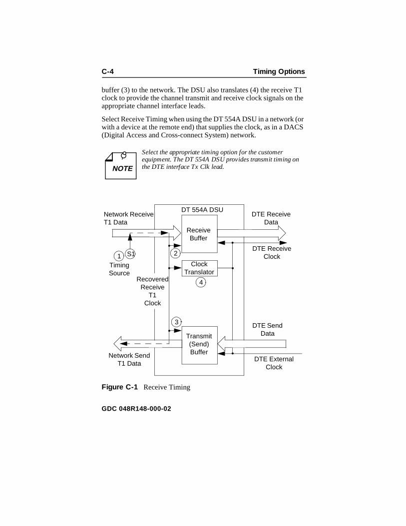
C-4 Timing Options
T1 the
(or CS
buffer (3) to the network. The DSU also translates (4) the receiveclock to provide the channel transmit and receive clock signals onappropriate channel interface leads.
Select Receive Timing when using the DT 554A DSU in a network with a device at the remote end) that supplies the clock, as in a DA(Digital Access and Cross-connect System) network.
Figure C-1 Receive Timing
Select the appropriate timing option for the customer equipment. The DT 554A DSU provides transmit timing onthe DTE interface Tx Clk lead.NOTE
Receive Buffer
Transmit (Send) Buffer
ClockTranslator
Network Receive T1 Data
DTE Receive Data
Network Send T1 Data
DTE Send Data
1
3
2
4
S1DTE Receive
Clock
DTE External Clock
RecoveredReceive
T1Clock
DT 554A DSU
Timing Source
GDC 048R148-000-02

Timing Options C-5
ing 4A ata 4A el face
Internal TimingWith Internal Timing, illustrated in Figure C-2, the DT 554A DSU provides the send timing source (1) for T1 data output from the transmit buffer (2) to the network. (This clock satisfies the requirements of a Stratum 4, Level II clock, as defined in AT&T Technical Reference 62411.) The remote DSU uses this as its timreference (3) and loops it back to the DT 554A DSU (4). The DT 55DSU recovers the receive T1 clock from the network receive T1 dand uses it to clock T1 data into the receive buffer (5). The DT 55DSU also translates (6) the receive T1 clock to provide the channtransmit and receive clock signals on the appropriate channel interleads.
Select Internal Timing when using the DT 554A DSU in a private network that does not provide timing (e.g., a non-DACS based service).
a. Configure only one DT 554A DSU in your network for Internal Timing, and configure the others for Receive Timing.
b. Select the appropriate timing option for the customer equipment: The DT 554A DSU provides transmit timingon the DTE interface Tx Clk lead.
NOTE
GDC 048R148-000-02

C-6 Timing Options
rce to
ta he el
Figure C-2 Internal Timing
DTE TimingWith DTE Timing, illustrated in Figure C-3, the customer equipmentconnected to the DSU DTEl interface provides its own channel transmit clock signal (1) on the appropriate interface lead. The DT554A DSU translates (2) this clock to provide the send timing soufor T1 data output from the transmit buffer (3) to the network. Theremote DSU uses this as its timing reference (4) and loops it backthe DT 554A DSU (5). The DT 554A DSU recovers the receive T1clock from the network receive T1 data and uses it to clock T1 dainto the receive buffer (6). The DT 554A DSU also translates (7) treceive T1 clock to provide the receive clock signals for the channon the appropriate interface leads.
Receive Buffer
Transmit (Send) Buffer
ClockTranslator
Network Receive T1 Data
DTE Receive Data
Network Send T1 Data
DTE Send Data
1
23
4
5
6
S1
DTE Receive Clock
DTE External Clock
Recovered Receive
T1Clock
DT 554A DSU
Timing Source
GDC 048R148-000-02

Timing Options C-7
ing t be rate
In order for this application to work, the DTE device that acts as timsource S1 must be the network source of timing. The DTE must nopassing along timing that is derived from another source or from a conversion.
Select DTE Timing when using the DT 554A DSU in a private network with the customer equipment supplying the clock.
Figure C-3 DTE Timing
Select the appropriate timing option for the customer equipment: The DT 554A DSU expects external timing onthe DTE interface Ext Clk lead.NOTE
Receive Buffer
Transmit (Send) Buffer
ClockTranslator
ClockTranslator
Network Receive T1
Data
DTE Receive Data
Network Send T1 Data
DTE Send Data
1
2
43
5
6
7
S1
DTE Receive Clock
DTE External Clock
Recovered Receive
T1Clock
DT 554A DSU
Timing Source
GDC 048R148-000-02
C-8 Timing Options
s
ock
rk. ide TE the he g
y
n
k.
DTE Split TimingDTE Split Timing, illustrated in Figure C-4, is a combination of Receive Timing and DTE Timing that utilizes two clock sources. Ain Receive Timing, the network (or a device at the remote end) provides one timing source (1). The DT 554A DSU recovers the receive T1 clock from the network receive T1 data and uses it to clT1 data into the receive buffer (2) and to provide the send timing source for T1 data output from the transmit buffer (3) to the netwoThe DT 554A DSU also translates (4) the receive T1 clock to provthe receive clock signal, on the appropriate interface lead. As in DTiming, the customer equipment on the channel interface providesother timing source, its own channel transmit clock signal (5) on tappropriate interface lead, but the DT 554A DSU uses it for nothinelse.
Select DTE Split Timing when there are timing sources provided bboth the network and the customer equipment.
a. Select the appropriate timing option for the customer equipment: The DT 554A DSU expects external timing othe DTE interface Ext Clk lead.
b. A ll timing options that include split timing require every timing source to be traceable to the same Stratum 1 cloc
NOTE
GDC 048R148-000-02

Timing Options C-9
le t the
are
de
Figure C-4 DTE Split Timing
Typical Network ApplicationsAlthough you can use the DT 554A DSU in various network configurations with different types of equipment, the following simpapplications illustrate the fundamental reasoning you use to selecappropriate timing option.
Back-to-Back ApplicationIn an in-house data communications network, two DT 554A DSUs connected back-to-back. The only component connecting them iscable, so there is no network to provide the timing source.
If the customer equipment connected to the channel cannot provi
Receive Buffer
Transmit (Send) Buffer
ClockTranslator
Network Receive T1
Data
DTE Receive Data
Network Send T1 Data
DTE Send Data
1
3
2
4
S1DTE Receive
Clock
DTE External Clock
Recovered Receive
T1Clock
DT 554A DSU
Timing Source
5
S2
Timing Source
GDC 048R148-000-02

C-10 Timing Options
ct
nt
DT
g h er ng
timing, select Internal Timing for the master or host end, and seleReceive Timing for the other, as shown in Figure C-5 A. In this example, the DT 554A DSU at Site A is configured for Internal Timing, making it the timing source.
If the customer equipment is to provide an external timing source,select DTE Timing for the DT 554A DSU connected to that equipmeand select Receive Timing for the other, as shown in Figure C-5 B. In this example, the host computer at Site A is providing timing, so its 554A DSU is configured for DTE Timing.
In the master/slave multiplexer application illustrated in Figure C-5 C, the multiplexer at Site A is configured as the master (i.e., the timinsource) and the multiplexer at Site B is configured as a slave. WitDTE Timing selected for both DT 554A DSUs, the master multiplexprovides timing and the slave multiplexer loops back timing so timiis dependent on the customer equipment.
A. DT 554A DSU at Site A Supplies Timing
DT 554A DSU
DT 554A DSU
Host Computer
Terminal
Site A Site B
Timing Option: Internal
Timing Option: Receive
Timing Source
GDC 048R148-000-02

Timing Options C-11
B. Customer Equipment at Site A Supplies Timing
C. Master/Slave Multiplexer Timing
Figure C-5 Typical Back-to-Back Applications
DT 554A DSU
DT 554A DSU
Host Computer
Terminal
Site A Site B
Timing Option:
DTE
Timing Option: Receive
Timing Source
DT 554A DSU
DT 554A DSU
Site A Site B
Timing Option:
DTE
Timing Option:
DTE
MUX MUX
Master Multiplexer –Timing Source
Slave Multiplexer –Loops Timing Back to DSU
GDC 048R148-000-02


D Alarm Definitions
r on
ing nt
e of al. ork
OverviewThis appendix describes the DT 554A DSU alarms that can appeathe terminal interface Monitor screen Alarm Status display:
Network OOF (Network Out of Frame)
Network LOS (Network Loss of Signal)
Network USS (Network Unavailable Signal State)
Network AIS (Network Alarm Indication Signal)
Network BPVS (Network Bipolar Violations)
Network CRCS (Network Cyclic Redundancy Checksum)
Network RYEL (Network Received Yellow Alarm)
Network LAD (Network Low Average Density)
Config Error (Configuration Error)
Network AlarmsNetwork Out Of FrameA Network Out Of Frame (NETWORK OOF) alarm event occurs when the DSU misses two out of four framing bits in the signal comfrom the network. The front panel OOF indicator reflects the currestatus of DSU-to-network synchronization.
Network Loss Of SignalA Network Loss of Signal (NETWORK LOS) alarm event occurs when the DSU senses an absence of network signal. The absencsignal for a time equivalent to 175 bits (± 75) is considered no signThe front panel LOS indicator reflects the current status of the netwsignal condition.
GDC 048R148-000-02
D-2 Alarm Definitions
nt nds thout
ate I)
ror
or de
ms nal.
s
ced k/mits RK
Network Unavailable Signal StateA Network Unavailable Signal State (NETWORK USS) alarm eveoccurs when 10 consecutive severely errored seconds occur. It ewhen the DSU has processed 10 consecutive seconds of data withe occurrence of a severely errored second.
Network Alarm Indication SignalA Network Alarm Indication Signal (NETWORK AIS) alarm event occurs when the DSU receives an AIS from the network.
Network Bipolar ViolationsA Network Bipolar Violation (NETWORK BPV) alarm event occurswhen the signal the DSU receives from the network does not alternbetween signal levels as required for Alternate Mark Inversion (AMor Bipolar with 8 Zero Substitution (B8ZS) data encoding.
The front panel BPV indicator reflects the current status of BPV erevents.
Network Cyclic Redundancy ChecksumA Network Cyclic Redundancy Checksum (NETWORK CRCS) erralarm event occurs when ESF framing is in use and the CRC-6 cocalculated at the receiving DSU does not match the CRC-6 code calculated by the DSU that transmitted the signal. The DSU perforthe CRC check on each ESF frame to detect errors in the DS1 sig
Network Received YellowA Network Received Yellow (NETWORK RYEL) alarm event occurwhen the DSU receives a Yellow alarm from the network.
Network Low Average DensityA Network Low Average Density (NETWORK LAD) alarm event occurs when the 8(N+1) Ones Density Requirement is being enfor(DSU operating mode either Unframed/AMI or Framed/AMI/Nx64Consecutive) and the DSU has to insert ones in the signal it transtoward the network. The DSU inserts ones and declares a NETWOLAD alarm when the signal from the DTE at its DTE interface portcontains fewer ones than the Ones Density option requires.
GDC 048R148-000-02

Alarm Definitions D-3
not
ber end
Configuration ErrorA Configuration Error (CONFIG ERROR) alarm indicates that theDSU has detected one of the following conditions:
• The checksum computed by the DSU for its configuration doesmatch the one it stored at the time the configuration was performed.
• The settings of switchbanks S11, Starting DS0, and S12, Numof DS0s, are such that the configured group of DS0s would extDS0s beyond number 24.
GDC 048R148-000-02


Index
Back Panel Connectors 2-13Configuration Option Settings 3-5Configuration Options
CSU Characteristics 2-4DS0 Assignments 2-10DTE Characteristics 2-8Network Characteristics 2-6
Configuration Screen 3-4Controls and Indicators 3-1Data Rate Selection 2-11Diagnostics Results Screen 3-10Diagnostics Selection Screen 3-9DTE Digital Loopback 4-21DTE Interface Port Connection 2-13DTE Interface 1-3DTE Local Loopback 4-19DTE Remote Digital Loopback with Self Test 4-23DTE Remote Digital Loopback 4-21DTE Self Test 4-17EIA-530 Interface Daughter Card Installation 2-14Equipment List 1-4Fault Isolation Procedure 4-3Features 1-1Fractional T1 Capabilities 1-2Front Panel Controls and Indicators 3-2Monitor Screen 3-11Network Connection 2-15Network Line Loopback 4-11Network Local Test with QRSS Self Test 4-13Network Local Test 4-13Network Payload Loopback 4-10Network QRSS Self Test 4-8Network Remote Test with QRSS Self Test 4-16Network Remote Test 4-14Option Selection 2-2
GDC 048R148-000-02

2 Index
Option Switchbanks, Location 2-3Preoperational Check 2-1Primary Power Connection 2-16Starting DS0 Selections 2-12Terminal Connection 2-16Terminal Interface
Configuration Screen 3-3Diagnostics Screen 3-8Monitor Screen 3-10Test Procedure 4-4What Are You? Screen 3-12
Timing Options 2-2Unpacking and Handling 2-1What Are You? Screen 3-12
GDC 048R148-000-02


General DataComm