table of contents - gdc.com msr 30 series routers system description table of contents i ... 3.1.2...
TRANSCRIPT

H3C MSR 30 Series Routers System Description Table of Contents
i
Table of Contents
Chapter 1 Introduction............................................................................................................. 1-1
Chapter 2 System Features ..................................................................................................... 2-1 2.1 Multiple Services Integration ......................................................................................... 2-1 2.2 New Storage Media....................................................................................................... 2-2
2.2.1 USB.................................................................................................................... 2-2 2.2.2 CF Card.............................................................................................................. 2-3
2.3 Routing & Switch Convergence..................................................................................... 2-4 2.4 IPv6 .............................................................................................................................. 2-4 2.5 A Rich of Interfaces....................................................................................................... 2-5 2.6 Feature-riched Services ................................................................................................ 2-6 2.7 Powerful Forwarding/Service Processing....................................................................... 2-8 2.8 High Reliability .............................................................................................................. 2-8 2.9 Superior QoS................................................................................................................ 2-9 2.10 Perfect Security Mechanism.......................................................................................2-10 2.11 Robust Route Policy...................................................................................................2-10 2.12 Integrated Network Management System ...................................................................2-11 2.13 Globalization Design ..................................................................................................2-11
Chapter 3 System Structure .................................................................................................... 3-1 3.1 View.............................................................................................................................. 3-1
3.1.1 MSR 30-20 Router View...................................................................................... 3-1 3.1.2 MSR 30-40 Router View...................................................................................... 3-2 3.1.3 MSR 30-60 Router View...................................................................................... 3-3
3.2 System Description ....................................................................................................... 3-3 3.2.1 Fixed interfaces .................................................................................................. 3-3 3.2.2 Interface Cards ................................................................................................... 3-4 3.2.3 Processor and Memory ....................................................................................... 3-5 3.2.4 Power Supply...................................................................................................... 3-5 3.2.5 Indicator Implications .......................................................................................... 3-6
3.3 Interface Attributes.......................................................................................................3-11 3.4 Supported Interface Cards ...........................................................................................3-19
3.4.1 Supported SIC Interface Cards ..........................................................................3-19 3.4.2 Supported Multifunctional Interface Modules (MIMs) ..........................................3-20 3.4.3 ESM Module......................................................................................................3-22 3.4.4 VPM and VCPM Module ....................................................................................3-22
Chapter 4 System Feature List and Performance Index......................................................... 4-1 4.1 H3C MSR 30 Series Feature List................................................................................... 4-1 4.2 System Performance Index of H3C MSR 30 Series Routers .......................................... 4-5

H3C MSR 30 Series Routers System Description Table of Contents
ii
Chapter 5 Applications and Solutions .................................................................................... 5-1 5.1 Network Application of Integrated Multiple Services....................................................... 5-1 5.2 Network Application of Comprehensive Services in Enterprises..................................... 5-1 5.3 Carrier Network Applications ......................................................................................... 5-2 5.4 IPv6 Network Application .............................................................................................. 5-3 5.5 MPLS VPN Network Application.................................................................................... 5-4 5.6 Network Application of Voice Services........................................................................... 5-5 5.7 Network Application of Security Services....................................................................... 5-6 5.8 Network Application of Integrated Routing and Switch ................................................... 5-7

H3C MSR 30 Series Routers System Description Chapter 1 Introduction
1-1
Chapter 1 Introduction
MSR 20/30/50 series routers are the next generation of MSR series routers that Huawei brought into the market on the basis of success in R series and AR 18/28/46 series routers. Upgraded and enhanced comprehensively based on the original routers in terms of hardware/software, this series of routers have improved price/performance ratio and mutliservice integration capability significantly. It is further divided into three series: MSR 20, MSR 30 and MSR 50, which are positioned in ascending order. MSR 20 and MSR 30 can be used as the edge access equipments of large networks or carrier networks, and the core of branches or small businesses; MSR 50 can be used as the core of large and medium-size enterprise networks as well as the edge/aggregation access equipments of large networks or carrier networks.
With VRP COMMWARE V5 network OS platform from Huawei-3Com, MSR 20/30/50 series routers continuously support software features of original R series and AR 18/28/46 series. For example, it offers feature-rich network security; supports SNA (System Network Architecture)/DLSw (Data-Link Switching); delivers backup center- and VRRP-based backup solutions; supports MPLS L3/L2 VPN, ADSL access, PPPoE Server/Client, IP multicast; and provides a rich of QoS (Quality of Service) features and so on. At the same time, VRP COMMWARE V5 OS platform supports IPv6 and other rich features. Additionally, MSR 20/30/50 series routers use international standards-compliant hardware and software, guaranteeing the interoperability with other products on all layers, and thus protecting users’ existing investments. As a result, the next generation of MSR series routers, combined with other series of Quidway routers and LAN Switches, can provide all-around and end-to-end network solutions for users in such industries as telecom, ISP (Internet Service Provider), financial service, tax, police, railway, education and electric power as well as large and medium-size enterprise users.
Here are the features of H3C MSR 20/30/50 series routers:
l A new software architecture: with the next generation of powerful, multi-services, scalable and componentized advanced OS platform Comeware V5 that Huawei-3Com has invested heavily, this series of routers provide a full support of IPv6 and the compatibility with IPv4. It not only supports the existing software features of V3, but also delivers feature-riched functions, satisfying the demanding requirements of networks and services.
l A smoothly scalable and advanced hardware architecture: This series of routers separate resources from services for higher resource utilization and investment protection. The built-in encryption engine can enhance encryption and meet increasingly rigorous security. Time Division Multiplex (TDM) slot switching function can bring higher local call competition rate and quality. High-density voice

H3C MSR 30 Series Routers System Description Chapter 1 Introduction
1-2
boards, crypto-accelerator boards and switching boards can improve performance and service integration. Use of common pinch cards and common LPUs makes it possible to smoothly integrate diverse services modules. In addition, a variety of extended services are available and new storages like USB and CF Flash are supported
l Integration of multiple services: By combining security, switching and voice services, this series of routers improves the integration of multiple services. For example, it provides world-class and innovative network security functions. As a result, you can realize a comprehensive integration of LAN switches and deploy voice gateways flexibly and conveniently.
l High performance/price ratio: By using the latest technologies in the industry, faster operating network processors and high integrated chipsets, this series of routers improves IP forwarding, service processing and data encryption performances whiling expanding interface density and strengthening software functions and services integration.
l Intelligent and auto-sensing network: This series of routers comes with quality analysis tools. You can dynamically adjust configuration according to the real network status, so as to provide a portfolio of solutions, such as service auto-sensing, security auto-sensing, reliability auto-sensing and intelligent management.
l Investment protection: This series of routers is fully compatible with all the modules and all the features of AR 18/28/46 series modularized routers to provide investment protection. At the same time, interface modules and software functions developed on the new series of routers can meet the application requirements of users at present and in the future, realizing investment protection in the future.
l Novel and fashionable appearance: Unlike the single and compact appearance of AR 18/28/46 series routers, this series of routers mixes popular and fashionable elements in appearance design. Modem and simple, it indicates the internal and external values of products properly.

H3C MSR 30 Series Routers System Description Chapter 2 System Features
2-1
Chapter 2 System Features
MSR 30 series is the mid-range products between MSR 20 series and MSR 50 series in the next generation of MSR series routers. MSR 30 series provides a variety of models and higher interface density and forward performances. It is intended to the center access equipments and network site access equipments of small- and mid-sized businesses as well as the edge access equipments of carrier networks.
Following are the features of the next generation of MSR series routers.
2.1 Multiple Services Integration
The next generation of MSR series routers allow enterprises to build a data, voice and IP phone integrated network on a single platform. Higher data and voice integration density brings voice over IP applications into a new stage while streamlining network operation management and reducing maintenance costs.
To support such a single platform integrating diverse services, the next generation of MSR series routers have redefined architecture. On the one hand, it meets the current services requirements of users. On the other hand, it provides means to extend services flexibly and protect user investments well.
Forwarding, security and voice features of the next generation of MSR series routers are boosted at a large extent than predecessors. Higher slot density is also available because of new built-in slots in the next generation of MSR series routers.
Multiple services integration of the next generation of MSR series routers includes the following features:
I. Comprehensive routing and switch convergence
The next generation of MSR series routers have realized integrated design and implementation in terms of hardware and software. You can use all the features of routers and switches seamlessly. See section 2.3 Routing & Switch Convergence for details.
II. Voice services
The next generation of software platform from Huawei-3Com, coupled with the new hardware voice design of the next generation of MSR series routers, Comware V5 provides mainstream voice communication protocols like H.323 and SIP, a variety of voice services such as emergency call, help in power off, dial-in policy, fax and E-PHONE, and diverse voice interfaces, including FXS/FXO/VE1/E&M.
With an extensible architecture, Digital Signal Processor (DSP) resources are allocated consistently in the next generation of MSR series routers. This brings higher DSP

H3C MSR 30 Series Routers System Description Chapter 2 System Features
2-2
resource utilization and access density. At the same time, local TDM switching is supported. On the one hand, voice quality is guaranteed. On the other hand, DSP resource occupation resulted from local calls is avoided and DSP resources are saved.
The next generation of MSR series routers provide flexible pinch card design. You can select it if necessary.
III. Security
Today, security becomes the basic function of a network. It is necessary to integrate security into the overall network. So a router plays an important role in network defense strategies. The next generation of MSR series routers can provide security services in conjunction with other services applications for its advanced, integrated and end-to-end security.
Comware V5 has extended security features further. Available security functions include Firewall, IPSec VPN, MPLS VPN, CA, Secure Shell (SSH) protocol 2.0, intrusion protection and simple network management protocol (SNMP v3) and so on.
Since security is directly integrated into the routers, the next generation of MSR series routers have a lot number of security accelerator hardware, including encryption function from hosts as well as MIM/FIC modules and ESM encryption engine for encryption.
IV. Balanced services and performance
The next generation of MSR series routers can provide users data, security, voice and video integrated services and upper layer applications, meeting their applications on the Internet at present and in the future without compromising original data transfer performance.
2.2 New Storage Media
The next generation of low-end and mid-range routers supports the use of new storage media like USB Flash and CF card for flexible scalability and investment protection. At the same time, many simple and convenient means are available for security and automatic service implementation.
2.2.1 USB
USB, the short of Universal Serial Bus, supports connecting several devices with a rate higher than common parallel ports and serial ports. There are two specifications of USB: USB 1.1 and USB 2.0, with up to 12Mbit/s and 480Mbit/s rates respectively. . USB is hot-swappable and plug-and-play.
Now, MSR 20/30/50 series routers support USB 1.1. With it, you can enjoy mission-critical storage and security functions, for example, provide a lot of Flash

H3C MSR 30 Series Routers System Description Chapter 2 System Features
2-3
memory for applications and configuration, store security VPN certification to build a secure VPN connection and distribute configuration safely.
I. USB Flash memory
USB Flash memory is attained to the router through a USB interface and can be detected automatically for plug-and-play. You only need to insert it in the USB interface of the router. USB Flash memory provides a choice of standby storage function. Comware software mirroring, configuration or other files can be replicated to USB Flash memory, and also then replicated to the router. As for reliability, it is compared to using CF (Compact Flash) card to save and recover files.
When it comes to supported file formats, USB Flash memory supports all the file formats supported on CF card (FAT16, FAT32). The configuration can be transferred from USB Flash memory to the router automatically for automatic configuration and deployment.
Huawei-3Com supports the following kinds of USB Flash memories: 64MB, 128MB, 256MB and 512MB.USB Flash memory provides a mechanism of backing up CF card. As USB Flash memory is widely used, using it to backup and recover files can bring in higher convenience and reliability for users.
II. USB application
With the introduction of USB interface, you can save the configuration of the router in USB Flash memory. After you insert the USB Flash memory holding the configuration in the USB interface, the router can get the configuration from the USB Flash memory, and then upgrade and update automatically. In this way, you can realize “zero-touch configuration and implementation.” That is, enterprises and carriers can upload boot configuration into the USB Flash memory. With the help of boot configuration, a remote site can build a connection to the master site, and then download the complete configuration to carry out deployment.
By leveraging the mentioned USB features, enterprises and carriers can carry out deployment over a network without uploading the configuration to routers before delivery and deployment, so as to realize low touch or zero touch configuration and deployment. In addition, manufacturers can ship routers to customers directly without configuration. As a result, the products can close the real requirements of customers for easy of use.
2.2.2 CF Card
Compact Flash Card (CF card), an advanced mobile storage, features high speed, high capacity, compact factor, light and low power consumption.
MSR 20/30/50 series routers support CF card. You can upgrade and replace CF card without opening the chassis. As for easy of use, it represents a design vision of personalization. As the software features and services of routers are changing, the size

H3C MSR 30 Series Routers System Description Chapter 2 System Features
2-4
of Comware V5 software platform is increasingly growing. A design to fix storage capacity is a risk and obstacle for software upgrading. Use of CF card can solve this issue. You can protect investments perfectly and provide ongoing service scalability for users.
2.3 Routing & Switch Convergence
SIC/MIM slots in the next generation of MSR series routers support many kinds of Layer 2 switching modules. In which MSR 30 series routers support 4/8/16/24-port SIC/DSIC/MIM/DMIM switching modules. Coupled with feature-riched switching of Comware V5 software platform, the next generation of MSR series can ensure comprehensive routing and switch convergence.
The Ethernet switch modules of the next generation of MSR series routers are capable of realizing Layer 2 switch LAN interface-to-Layer 3 WAN interface conversion. In case of access to Ethernet, up to four Layer 3 WAN interfaces can be configured to facilitate flexible networking.
The Ethernet switch modules of the next generation of MSR series routers allow for perfect Layer 2 Ethernet switch features and related protocols, for example, VLAN, MAC address management, STP, port aggregation LACP, 802.1x and QoS/ACL and so on. Where SIC/DSIC cards are designed to implement low density access switches that provide basic Layer 2 switch feature; MIM/DMIM cards are designed to implement high density access and aggregation switches that provide intelligent and scalable Layer 2 switch feature. MIM/DMIM cards are hot-swappable. DMIM card comes with photoelectric Combo GE interface to enable access in different distances. At the same time, GE interface interconnection can be used to realize expansion of ports and VLAN domain between modules.
Plug-in cards with different densities and different features can adapt to different user requirements while streamlining networking. Multi-services routers work well when switch modules enable L2 wire speed forwarding, meeting the requirements of routing and switch integration and replacing the networking of traditional routers and Ethernet switches in deed. As a result, users can use and manage devices flexibly.
2.4 IPv6
Today’s Internet is running on the basis of IPv4 protocol. With the rapid development of the Internet, limited address space defined by IPv4 will be exhausted. Short of address will make an adverse effect on the continuous development of the Internet, and severely restrict the application of IP technologies and the prospect of networks in the future. IPv6, as the basis of the next generation of networks, is broadly recognized for its outstanding technical advantages, which are shown as follows:.
l Flexible header format l Larger address space

H3C MSR 30 Series Routers System Description Chapter 2 System Features
2-5
l Valid hierarchical addressing and routing system l Full state and stateless address configuration l Built-in security l QoS l Robust negotiation mechanism for neighbor discovery l Scalability l Meeting mobile requirements (3GPP determined to use IPv6 to build the next
generation of IPv6 core network)
The next generation of MSR series routers support the following IPv6 features:
l IPv6 address l Local link unicast address l Local site unicast address l Global unicast address l Multicast address l IPv6 Neighbor Discovery l Neighbor Discovery (ND) host l Neighbor Discovery (ND) router l IPv6 Path MTU l IPv6 ACL l IPv6 routing protocol l IPv4 to IPv6 migration l Network Address Translation-protocol Translation) NAT-PT l Packet and message translation l IPv6-IPv4 tunneling
2.5 A Rich of Interfaces
The next generation of MSR series routers come with a rich of physical interfaces. General interfaces include: syn/asyn serial interface, Ethernet interface, E1/T1 interface, E1-F/T1-F interface, E3/T3 interface, ISDN BRI/PRI interface analog modem (AM) interface, voice interface, SDH interface and Ethernet port and so on.
l Ethernet interfaces: FE and GE; l Frame relay interfaces: E1/T1, E1-F/T1-F, syn serial interface, E3/T3; l X.25 interfaces: E1/T1, E1-F/T1-F, syn serial interface, E3/T3; l ISDN interfaces: ISDN BRI, ISDN PRI; l PSTN interfaces: asyn serial interface, E1/T1, AM, ADSL2+; l DDN network interfaces: syn/asyn serial interface, E1/T1, E1-F/T1-F, E3/T3; l Voice interfaces: analog voice interfaces (including FXS/FXO/E&M), digital voice
interfaces (including VE1/VT1); l USB interface: USB 1.1; l Layer 2 Ethernet ports; l POS interface.

H3C MSR 30 Series Routers System Description Chapter 2 System Features
2-6
2.6 Feature-riched Services
The next generation of MSR series routers provide a large number of services as follows:
I. xDSL
The next generation of MSR series routers have an optional SIC-ADSL2+ interface card. SIC-ADSL2+ offers common phone interfaces. By leveraging digital code modulation technology, you can access digital subscriber line access multiplexer (DSLAM) devices through the existing copper phone lines and obtain higher data transmission capacity.
With ATM adaptation layer 5 (AAL5) as the ATM adaptation layer protocol, the next generation of MSR series routers provide traffic services like constant bit rate (CBR), variable bit rate (VBR) and unspecified bit rate (UBR). Many issues, such as IP packet over ATM, authentication and accounting, are also solved through IPoA, PPPoA and PPPoEoA technologies. This series of routers is applicable to high speed data services and transmission of larger data packets, helping small- and medium-sized enterprises networks to access the Internet directly through broadband.
II. MPLS VPN and traditional VPN
The next generation of MSR series routers support Layer 2 and Layer 3 tunneling protocols. Layer 2 tunneling protocol (L2TP) is helpful for users to enable dial-in virtual private data network (VPDN) and leased-line VPN services. Layer 3 tunneling protocol is enabled based on generic routing encapsulation (GRE) protocol. Combined with IPSec technology, it provides a full set of network security solutions for leased-line VPN, including access control, connectionless integrity and data source authentication, anti-replay, encryption and traffic classification and encryption. Both tunneling protocols can be used independently or jointly to provide better services.
MPLS is the combination of IP and ATM. It uses a short, fixed long label to replace IP header to identify data flows and as the basis of forwarding to provide higher forwarding rate. With the support of IP routing protocol and control protocol, MPLS can meet the network requirements of diverse new applications. In a MPLS network, tagged packets are transferred along the label switched path (LSP) made up of a series of label switch routers (LSRs). Using MPLS to enable VPN is of natural advantages because LSP itself is a tunnel on the public network. MPLS VPN refers to combine the geographical branches of a private network into a unified network. It supports the reuse of IP addresses between branches and interoperation between VPNs. MSR 20/30/50 series routers can function as not only label edge routers (LERs) but also label switch routers (LSRs). When MSR 20/30/50 series routers locate at the edge of a label domain, they as LERs can connect MPLS domains and non-MPLS domains as well as different MPLS domains, and classify services, distribute labels, encapsulate or strip off

H3C MSR 30 Series Routers System Description Chapter 2 System Features
2-7
multi-tier labels. When the next generation of MSR series run in a MPLS domain, they can exchange labeled packets.
III. DCC
The next generation of MSR series routers bring perfect dial-in solutions for users, with Circular DCC and Resourced-Shared DCC two dial-in modes supported. In some cases, a connection is built and communication is carried out between routers only when there are messages need to transfer. So the transferred messages are time-free, small in volume and unexpected. DDC comes into being to offer a flexible and cost-effective solution for users. Especially, Resource-Shared DCC is more perfect. It allows more than one dial-in user to share physical interfaces and make different calls through dialer pool. In real circumstances, DCC generally is used in backup mode to guarantee the master line communication. When the master line cannot communicate services due to a line failure or other reasons, DCC provides a backup line to guarantee the operation of services. In addition, DCC can enable callback, including PPP callback, ISDN calling line identification callback.
IV. Voice
The next generation of MSR series routers provide mainstream voice communication protocols like H.323 and SIP for a variety of voice services such as emergency call/dial-in policy/fax/E-PHONE, and a variety of voice interfaces such as FXS/FXO/VE1/VT1/E&M.
By employing high performance digital signal process (DSP) chipset and high compression ratio coding/decoding algorithm, combined with the features from Comware V5 software platform like security, QoS and policy-based routing, the next generation of MSR series routers can ensure the transmission of voice over IP through silence compression, comfortable noise and anti-jitter measures.
Two connection modes are supported: quick connection and non-quick connection. The next generation of MSR series routers carry out out-band transmission of dual tone multi-frequency (DTMF) codes with tunneling while offering busy tone detection and some special services for PBX (for example, Do-Not-Disturb, transfer in busy and alarm clock).
Voice processing module (VPM) is also supported. It is a DSP array and easy of upgrading and expansion. All VE1 and VT1 interface cards share DSP resources of VPM, saving user investments and maximizing hardware resources.
The next generation of MSR series routers provide a rich of voice interfaces that can not only directly connect to general phones/faxes, but also connect to PBX switches through trunks like AT0 and E1/T1. It realizes the interoperation with voice gateways from other vendors well in addition to high density and qualified voice and fax communications, protecting the existing investments of users effectively. When E1 trunk is used to connect a PBX, R2 signaling as well as DSS1 and Q.SIG signaling on ISDN PRI interface are supported. One-stage/dual-stage dial-in services are available.

H3C MSR 30 Series Routers System Description Chapter 2 System Features
2-8
Synchronous transmission of voice and data on PRI interface is also supported. As a result, the utilization is improved and the scope of supported services is enlarged.
The next generation of MSR series routers offer Gateway Keeper (GK) Client function that maintains communications with GK Server through Registration, Admission and Status (RAS) signaling. In this way, GK Server provides H3C voice gateway services like access permission, address translation, bandwidth management and voice gateway management. At the same time, it can network with mainstream voice gateway flexibly. This makes the next generation of MSR series routers fit for large- and medium- sized voice communications in enterprises.
By compressing redundant information like voice header on low-speed PPP serial links, IP Header Compression (IPHC) reduces the bandwidth occupied by voice channels significantly and maximizes network resources.
The next generation of MSR series routers provide voice RADIUS function. When a voice call occurs, the router reports statistics including call duration, number of packets and number of bytes to RADIUS Server for accounting.
2.7 Powerful Forwarding/Service Processing
IP packet forwarding efficiency is a key index for performance measurement. When the router forwards a packet according to general procedure, it needs to look up the routing table based on the network layer information of the packet to determine a best path for forwarding. And each subsequential packet will be processed by this process repeatedly. In addition to flexible services and protocol processing, the next generation of MSR series routers use advanced quick route search algorithm to enable fast forwarding, improving forwarding and services processing capabilities significantly. The next generation of MSR series routers support fast forwarding on a variety of high speed link interfaces. It can also forward packets rapidly in conjunction with QoS and firewall.
2.8 High Reliability
I. Hot-swappable power supply/interface card/fan
According to carrier-class product requirements, the next generation of MSR series routers are designed to support RPS redundant power supply, so as to meet the high reliability requirements of carrier-class networks on devices.
II. Backup center and VRRP
With Backup Center and VRRP, the next generation of MSR series routers provide a backup solution in case of a communication line or device failure to guarantee smooth data communication, and thus boosting network robusticity and reliability effectively. Backup Center supports backup load balancing.
H3C MSR 30 Series Routers System Description Chapter 2 System Features
2-9
III. External storages like CF card and USB Flash memory
CF card and USB Flash memory can be used to store many system files and configuration to improve system reliability. External storages can accommodate a large volume of system logs and security logs for backing up, browsing and archiving.
2.9 Superior QoS
The next generation of MSR series routers are developed based on Comware V5 platform. The QoS of V5 platform inherits all the QoS features of previous Comware versions. That is, it supports Diff-Serv standard well. At the same time, it adds the supports of IPV6 QoS as well as MPLS Traffic Engineering (MPLS TE) and MPLS Resource Reservation Setup Protocol (MPLS RSVP).
QoS Diff-Serv model includes traffic classification, traffic policing, traffic shaping, queue management and queue scheduling that completely enables six sets of PHB services (EF, AF1 to AF4, BE) defined in standards. This allows network operators to provide users different QoS levels of service guarantee, making the Internet a real data, voice and video integrated network.
The enablement of Differentiated Service (Diff-Serv) includes traffic classification, traffic policing (CAR), traffic shaping (GTS), congestion management (PQ/CQ/WFQ/CBQ) and congestion avoidance (WRED).
l Traffic classification: identify interesting objects by a certain matching rule. Traffic classification is the premise for differentiated services.
l Traffic policing: monitor the specifications of the specified traffic flowed into the router. Once the traffic has exceeded the specifications, you can take restriction or punishment actions to protect the business interests and network resources of operators.
l Congestion management: measures you must take to settle resource competition in case of network congestion. Generally, it places packets in a queue for caching and uses a scheduling algorithm to determine the forwarding order.
l Congestion avoidance: too congestion may damage network resources. Congestion avoidance monitors the utilization of network resources. When it finds that the congestion is aggravating, it drops packets proactively and relieve network overload by adjusting traffic.
l Traffic shaping: a traffic control measure that actively adjusts the traffic output rate. Generally, it is used to adapt to the available network resources from the downstream routers and avoid unnecessary packet drop and congestion.
MPLS traffic engineering (MPLS TE) is a QoS technology based on Int-serv module. By combining traffic engineering and MPLS, you can establish a LSP tunnel to the designated path and reserve resources. So network traffic can bypass congested nodes for the purpose of balancing. The next generation of MSR series routers can use QoS in a MPLS network flexibly. Furthermore, it can use original QoS of Diff-Serv for

H3C MSR 30 Series Routers System Description Chapter 2 System Features
2-10
CE and PE routers and QoS of Int-Serv for MPLS aggregation/core networks to realize real end-to-end QoS guarantee.
2.10 Perfect Security Mechanism
The next generation of MSR series routers have many authentication methods (plain text authentication and MD5) and support two kinds of user authorization modes: local authentication and RADIUS authentication that can authenticate user IDs and authorization to prevent from illegal configuration of devices.
The ACL feature of the next generation of MSR series routers is used to create a combination of rules that permit or deny based on source/destination IP address segments (including host address) or source/destination ports. This is applicable to the following cases where you can control access to the traffic on the user side or the network side and set the rights to access local information network or WAN by users for the purpose of protecting key servers, protecting system users, restricting foreign access, preventing from network attacks and supporting real-time updating.
The network address translation (NAT) feature of the next generation of MSR series routers allows for translation and recovery of IP addresses and ports. At the same time, it allows the Intranet to provide limited access to internal hosts by user configurations. The feature can also meet high capacity and high performance to adapt to the position of the next generation of MSR series routers in a network. In addition to above mentioned basic functions, the NAT feature of the next generation of MSR series routers limits the number of concurrent connections of individual users. As a result, it can reduce network strike from malicious resource occupation while meeting general network applications. You can output address translation information through logs to analysis network failures and locate hidden security troubles. The NAT feature provides application layer gateway (ALG) function for common specific application layer FTP and ICMP.
Furthermore, H3C MSR 50 series routers have plenty of statistics including traffic statistics, traffic sample and NAT information statistics.
2.11 Robust Route Policy
Route policy consists of a series of rules which are broken into three types used for route publication, route receiving and route import respectively. Route policy is referred to as route filtering, because defining a policy is equivalent to defining a set of filters and applying these filters before the receiving/publication of a route information or the exchange of route information between different protocols.
Route policy is used with routing protocols to strengthen the control of routing protocols. When exchanging route information with the peer, a upper layer routing protocol may need to only receive or publish a part of route information meeting the specified conditions; when importing the route information of other routing protocols, the route

H3C MSR 30 Series Routers System Description Chapter 2 System Features
2-11
protocol may need to only import a part of route information meeting the conditions, and set some attributes of the imported route information to satisfy the requirements of the protocol. Route policy is the way to enable these functions for route protocols.
Route policies supported on the next generation of MSR series routers including route policy definition, route import and distribution definition and restriction rules like route prefix, autonomous system path, community attribute and access list. The use of route policy is of greater practical value for the manageability of enhanced a network.
2.12 Integrated Network Management System
Quidview V3 is the next generation of network management system self-developed by Huawei-3Com. With componentized structure design, Quidview enables lots of functions like device management, VPN monitoring and deployment, software upgrade management, configuration management, alarm management, performance management and WEB report through the installation of different service components. Quidview provides a perfect solution to facilitate monitor, maintain and manage your networks, no matter you are enterprise network user, campus networks users or operators.
In case of independent installation, Quidview device management components can integrate with common network management platforms in the industry, for example, SNMPc, HP Openview.
The next generation of MSR series routers have many maintenance means like local maintenance, remote maintenance and centralized maintenance, and provide a full set of alarm, test, diagnosis, trace and log functions for daily maintenance and management.
2.13 Globalization Design
According to UL, CE and FCC standards, the next generation of MSR series routers are designed to conform to certification requirements in home, Europe and North American.
See Comware V5 Software Platform Product Overview for detailed software functions.

H3C MSR 30 Series Routers System Description Chapter 3 System Structure
3-1
Chapter 3 System Structure
H3C MSR 30 series routers use an integrated design. MSR 30-60 is 3U high, MSR 30-40 is 2U high and MSR 30-20 is 1U (1U = 44.45mm) high respectively. H3C MSR 30-20/30-40/30-60 routers have the same overall chassis layout that can be installed in 19in standard racks.
3.1 View
3.1.1 MSR 30-20 Router View
I. Front view
Figure 3-1 MSR 30-20 front view
II. Rear view
Figure 3-2 MSR 30-20 rear view
MSR 30-20 is 1U high. There are one CF card slot, one CONSOLE port, one AUX port, two USB Host interfaces on the front panel and two GE interfaces, four SIC interface card slots (two horizontal slots can be combined to support DSIC) and two MIM interface card slots on the rear panel. Power input locates on the front panel, with AC and RPS power supplies supported.

H3C MSR 30 Series Routers System Description Chapter 3 System Structure
3-2
3.1.2 MSR 30-40 Router View
I. Front view
Figure 3-3 MSR 30-40 front view
II. Rear view
Figure 3-4 MSR 30-40 rear view
MSR 30-40 is 2U high. There are one CF card slot, one CONSOLE port, one AUX port, two USB Host interfaces on the front panel, and 2-GE Combo interface RJ 45 and SFP connectors, four SIC interface card slots (two horizontal slots can be combined to support DSIC) and four MIM interface card slots (two horizontal slots can be combined to support DMIM) on the rear panel. Power input locates on the front panel, with AC and RPS power supplies supported.

H3C MSR 30 Series Routers System Description Chapter 3 System Structure
3-3
3.1.3 MSR 30-60 Router View
I. Front view
Figure 3-5 MSR 30-60 front view
II. Rear view
Figure 3-6 MSR 30-60 rear view
MSR 30-60 is 3U high. There are one CF card slot, one CONSOLE port, one AUX port, two USB Host interfaces on the front panel, and 3-GE Combo interface RJ 45 and SFP connectors, four SIC interface card slots (two horizontal slots can be combined to support DSIC) and four MIM interface card slots (two horizontal slots can be combined to support DMIM) on the rear panel. Power input locates on the front panel, with AC and RPS power supplies supported.
3.2 System Description
3.2.1 Fixed interfaces
Table 3-1 H3C MSR 30-20/30-40/30-60 fixed interfaces
Item MSR 30-20 MSR 30-40 MSR 30-60 Fixed Console 1 1 1

H3C MSR 30 Series Routers System Description Chapter 3 System Structure
3-4
AUX 1 1 1 USB 2 2 2
GE Two electrical interfaces
Two GE Combo interfaces
Two GE Combo interfaces
interfaces
FE 0 0 0
& Note:
l GE Combo interface means that there is only one GE interface in the board but one electrical interface and one optical interface outside. You can use them if necessary. Using electrical interface and optical interface simultaneously is prohibited. When cables and optical fibers are connected simultaneously, by default electrical interface works.
l Of two USB 2.0 interfaces, USB 0 supports Host or Device mode; USB 1 supports only Host mode.
3.2.2 Interface Cards
Table 3-2 H3C MSR 30-20/30-40/30-60 interface cards
Item MSR 30-20 MSR 30-40 MSR 30-60
SIC 4 SICs or 2 DSICs
4 SICs or 2 DSICs
4 SICs or 2 DSICs External
modules MIM 2 4 MIMs or 1
DMIM 6 MIMs or 2 DMIMs
ESM 2 2 2 VCPM 1 1 1 Internal
modules VPM 2 3 3
& Note:
l Two horizontal SIC slots can be combined a large slot supporting DSIC; two horizontal MIM slots can be combined a large slot supporting DMIM;
l VPM (DSP strip) must be used with VCPM (voice co-processing) pinch card for the decompression of multiple digital voice (E1/T1) lines.

H3C MSR 30 Series Routers System Description Chapter 3 System Structure
3-5
3.2.3 Processor and Memory
Table 3-3 H3C MSR 30-20/30-40/30-60 processor and memory
Item MSR 30-20 MSR 30-40 MSR 30-60
Processor PowerPC 533MHz PowerPC 667MHz PowerPC 667MHz
Boot ROM 4M 4M 4M
Memory DDR SDRAM: Default: 256MB Maximum: 1GB
DDR SDRAM: Default: 256MB Maximum: 1GB
DDR SDRAM: Default: 256MB Maximum: 1GB
CF card Default: 256MB Maximum: 256MB
Default: 256MB Maximum: 256MB
Default: 256MB Maximum: 256MB
& Note:
l Boot ROM holds the boot files used for startup. l Memory holds the communication data with CPU when the system works. l CF card (256M) holds the software and configuration of the system. When the
software is reading or writing from/to a CF card, the CF card indicator goes on. At this time you cannot draw out the CF card. Otherwise the files stored in the CF card will be damaged.
3.2.4 Power Supply
Table 3-4 Other H3C MSR 30-20/30-40/30-60 hardware
Item MSR 30-20 MSR 30-40 MSR 30-60
442 X 441.8 X 44.2mm
442 X 422.3 X 88.2mm
442 X 421.8 X 132mm Dimension (H×W×D)
(with feet/without rack-mounting ear)
(17.4 X 17.39 X 1.74 in.)
(17.4 X 16.63 X 3.47 in.)
(17.4 X 16.6 X 5.2 in.)
Weight 6.5Kg (14.33lb) 8Kg(17.64lb) 10Kg(22.05lb)

H3C MSR 30 Series Routers System Description Chapter 3 System Structure
3-6
Input AC voltage
Rated voltage range: 100VAC to 240VAC; 50Hz/60Hz
Rated voltage range: 100VAC to 240VAC; 50Hz/60Hz
Rated voltage range: 100VAC to 240VAC; 50Hz/60Hz
Maximum power 125W 210W 210W
Operating temperature 0 °C to 40°C 0 °C to 40°C 0 °C to 40°C
Relative humidity (noncondensing) 5% to 90% 5% to 90% 5% to 90%
& Note:
MSR 30 series routers support AC and RPS power supplies. You can use different power supplies according to different applications.
3.2.5 Indicator Implications
I. MSR 30-20 indicator implications
Figure 3-7 Front panel of MSR 30-20 MPU
Table 3-5 Implications of indicators on the front panel of MSR 30-20 MPU
Indicator Monochromatic/dichromatic Quantity Status Function
Go on in green
The board supplies power well.
PWR Monochromatic 1
Go off The board does not supply power.

H3C MSR 30 Series Routers System Description Chapter 3 System Structure
3-7
Flashing in green (0.5Hz)
The system works well.
Flashing in green (4Hz)
Starting up the system
Go off No input voltage or MPU failure
SYS Dichromatic 1
Go on in yellow Failure
Go on in green
Attained to the Host and hot-swappable USB
(device) Monochromatic 1
Go off Not being attained to the Host
Go on in green
CF card is on, and success in host examination.
Flashing in green
The system is accessing CF card. Do not insert or draw out.
Go on in yellow
CF card is on, but failure to host examination.
CF Dichromatic 1
Go off CF card is not inserted or recognizable.
Figure 3-8 Rear panel of MSR 30-20 MPU

H3C MSR 30 Series Routers System Description Chapter 3 System Structure
3-8
Table 3-6 Implications of indicators on the rear panel of MSR 30-20 MPU
Indicator Monochromatic
/dichromatic Quantity Status Function
Go on in green VPMx is on and valid.
Go on in yellow VPMx is on but invalid.
VPM0 through VPM1
Dichromatic 2
Go off VPMx is off.
Go on in green ESMx is on and valid.
Go on in yellow VPMx is on but invalid.
ESM0 through ESM1
Dichromatic 2
Go off VPMx is off.
Go on in green VCPM is on and valid.
Go on in yellow VCPM is on but invalid.
VCPM Dichromatic 1
Go off VCPM is off.
Go on in orange 100M/10M connection is established
Flashing in orange Receive/send data at 100M/10M
Go on in green 1000M connection is established
Flashing in green Receive and send data at 1000M
CE0 through CE 1 (two indicators contained by the connector)
Dichromatic 2
Go off No connection

H3C MSR 30 Series Routers System Description Chapter 3 System Structure
3-9
II. MSR 30-40/30-60 indicator implications
Figure 3-9 Front panel of MSR 30-40/30-60 MPU
Table 3-7 Implications of indicators on the front panel of MSR 30-40/30-60 MPU
Indicator Monochromatic
/dichromatic Quantity Status Function
Go on in green The board supplies power well.
PWR Monochromatic 1
Go off The board does not supply power.
Flashing in green (0.5Hz)
The system works well.
Flashing in green (4Hz)
Starting up the system
Go off No input voltage or MPU failure
SYS Dichromatic 1
Go on in yellow Failure
Go on in green Attained to the Host and hot-swappable USB
(device) Monochromatic 1
Go off Not being attained to the Host
CF Dichromatic 1 Go on in green
CF card is on, and success in host examination.

H3C MSR 30 Series Routers System Description Chapter 3 System Structure
3-10
Flashing in green
The system is accessing CF card. Do not insert or draw out.
Go on in yellow
CF card is on, but failure to host examination.
Go off CF card is not inserted or recognizable.
Figure 3-10 Rear panel of MSR 30-40/30-60 MPU
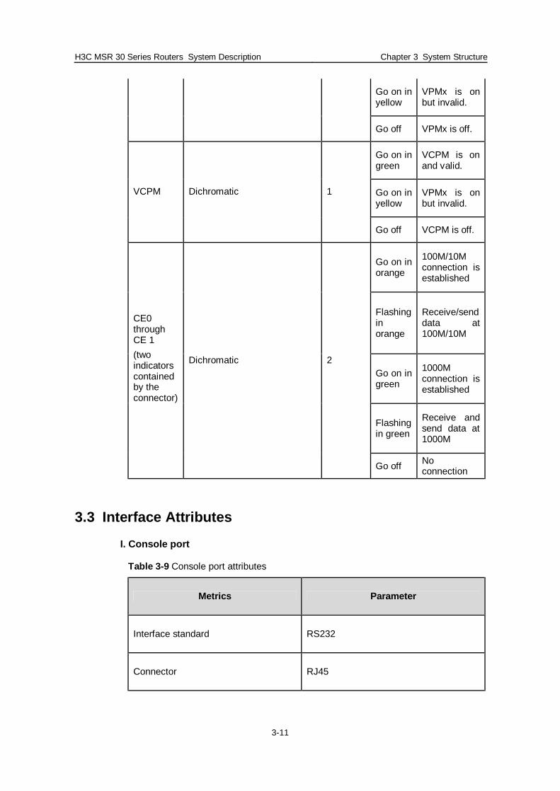
Table 3-8 Implications of indicators on the rear panel of MSR 30-40/30-60 MPU
Indicator Monochromatic/dichromatic Quantity Status Function
Go on in green
VPMx is on and valid.
Go on in yellow
VPMx is on but invalid.
VPM0 through VPM2
Dichromatic 3
Go off VPMx is off.
ESM0 through ESM 1
Dichromatic 2 Go on in green
ESMx is on and valid.
H3C MSR 30 Series Routers System Description Chapter 3 System Structure
3-11
Go on in yellow
VPMx is on but invalid.
Go off VPMx is off.
Go on in green
VCPM is on and valid.
Go on in yellow
VPMx is on but invalid.
VCPM Dichromatic 1
Go off VCPM is off.
Go on in orange
100M/10M connection is established
Flashing in orange
Receive/send data at 100M/10M
Go on in green
1000M connection is established
Flashing in green
Receive and send data at 1000M
CE0 through CE 1 (two indicators contained by the connector)
Dichromatic 2
Go off No connection
3.3 Interface Attributes
I. Console port
Table 3-9 Console port attributes
Metrics Parameter
Interface standard RS232
Connector RJ45

H3C MSR 30 Series Routers System Description Chapter 3 System Structure
3-12
Rate 9600bps to 115200bps
II. USB interface
Table 3-10 USB interface attributes
Metrics Parameter
Interface standard USB2.0
Connector USB Host
Rate 1.2 Mbps to 12 Mbps
Interface mode Host/Device
III. FE Electrical Interface
Table 3-11 FE electrical interface attributes
Metrics Layer 2 FE electrical interface parameter
Layer 3 FE electrical interface parameter
Interface standard 10/100Base-TX 10/100Base-TX
Interface type MDI/MDIX MDI
Connector RJ45 RJ45
Rate 10/100Mbps 10/100Mbps
10/100Mbps auto-sensing 10/100Mbps auto-sensing Operating mode
Full duplex/ half duplex Full duplex/ half duplex
H3C MSR 30 Series Routers System Description Chapter 3 System Structure
3-13
Supporting only Layer 2 switching
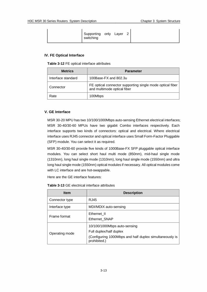
IV. FE Optical Interface
Table 3-12 FE optical interface attributes
Metrics Parameter
Interface standard 100Base-FX and 802.3u
Connector FE optical connector supporting single mode optical fiber and multimode optical fiber
Rate 100Mbps
V. GE Interface
MSR 30-20 MPU has two 10/100/1000Mbps auto-sensing Ethernet electrical interfaces; MSR 30-40/30-60 MPUs have two gigabit Combo interfaces respectively. Each interface supports two kinds of connectors: optical and electrical. Where electrical interface uses RJ45 connector and optical interface uses Small Form-Factor Pluggable (SFP) module. You can select it as required.
MSR 30-40/30-60 provide five kinds of 1000Base-FX SFP pluggable optical interface modules. You can select short haul multi mode (850nm), mid-haul single mode (1310nm), long haul single mode (1310nm), long haul single mode (1550nm) and ultra long haul single mode (1550nm) optical modules if necessary. All optical modules come with LC interface and are hot-swappable.
Here are the GE interface features:
Table 3-13 GE electrical interface attributes
Item Description
Connector type RJ45
Interface type MDI/MDIX auto-sensing
Frame format Ethernet_II Ethernet_SNAP
Operating mode
10/100/1000Mbps auto-sensing Full duplex/half duplex (Configuring 1000Mbps and half duplex simultaneously is prohibited.)

H3C MSR 30 Series Routers System Description Chapter 3 System Structure
3-14
Table 3-14 GE optical interface attributes
Item Description
Connector type SFP/LC
Interface standard 802.3, 802.3u and 802.3ab
Type
Short-haul multi mode (850nm)
Mid-haul multi mode (1310nm)
Long haul (1310nm)
Long haul (1550nm)
Ultra long haul (1550nm)
Min. -9.5dBm -9dBm -2dBm -4dBm -4dBm
Transmitting optical power
Max. 0dBm -3dBm 5dBm 1dBm 2dBm
Receiving sensitivity -17dBm -20dBm -23dBm -21dBm -22dBm
Core wave length 850nm 1310nm 1310nm 1550nm 1550nm
Optical fiber type
62.5/125μm multi mode optical fiber
9/125μm single mode optical fiber
9/125μm single mode optical fiber
9/125μm single mode optical fiber
9/125μm single mode optical fiber
Maximum transmission distance
0.55km 10km 40km 40km 70km
Operating mode 1000 Mbps full duplex
VI. AUX port
Table 3-15 Aux port attributes
Metrics Parameter
Interface standard RS232 (supporting remote Modem configuration)
Connector RJ45
Rate 9600bps to 115200bps

H3C MSR 30 Series Routers System Description Chapter 3 System Structure
3-15
VII. Synchronous serial port
Table 3-16 Synchronous serial port attributes
Metrics Parameter
Interface standard V.24 (DTE/DCE), V.35 (DTE/DCE), X.21 (DTE/DCE), RS449 (DTE/DCE) and RS530 (DTE/DCE)
Connector DB28
Rate 1200Mbps to 2.048Mbps (baud rate (bps): 1200, 4800, 9600, 19200, 38400, 115200, 56000, 64000, 72000, 128000, 384000 and 2048000)
VIII. Asynchronous serial port
Table 3-17 Asynchronous serial port attributes
Metrics Parameter
Interface standard V.24 (DTE/DCE)
Connector RJ45
Rate 300kbps to 115.2Kbps (baud rate (bps): 300, 600, 1200, 4800, 9600, 19200, 38400, 57600 and 15200)
IX. AM interface
Table 3-18 AM interface attributes
Metrics Parameter
Interface standard G.712
Connector RJ45
Bandwidth 300Hz to 3400Hz
X. CE1/PRI and CT1/PRI interfaces
Table 3-19 CE1/PRI and CT1/PRI interface attributes
Metrics Parameter
Interface standard G.703 and G.704
Connector DB15 (FIC-1E1/ FIC-2E1) DB25 (FIC-4E1) RJ45 (FIC-1T1/ FIC-2T1/ FIC-4T1)
Rate CE1/PRI: 2.048Mbps (n×64k bps, n=1...31) CT1/PRI: 1.544Mbps (n×64k or 56kbps, n=1...24)

H3C MSR 30 Series Routers System Description Chapter 3 System Structure
3-16
XI. E1-F and T1-F interfaces
Table 3-20 E1-F and T1-F interface attributes
Metrics Parameter
Interface standard G.703 and G.704
Connector DB15 (FIC-1E1-F/ FIC-2E1-F) DB25 (FIC-4E1-F) RJ45 (FIC-1T1-F/FIC-2T1-F/FIC-4T1-F)
Rate CE1/PRI: 2.048Mbps (n×64kbps, n=1...31) CT1/PRI: 1.544Mbps (n×64k or 56kbps, n=1...24)
XII. Standard CE3/CT3 interface
Table 3-21 CE3/CT3 interface attributes
Metrics Parameter
Interface standard G.703 and G.704
Connector SMB
Rate CE3: 34.368Mbps CT3: 44.736Mbps
XIII. ISDN BRI interface
Table 3-22 ISDN BRI interface attributes
Metrics Parameter
Interface standard ISDN BRI interface
Connector RJ45
Rate 64Kbps and 2B+D
XIV. ATM-E1/T1 and IMA group interfaces
Table 3-23 IMA group interface attributes
Metrics Parameter
Interface standard ITU-G.703 and ITU-G.704
Connector DB68
Operating mode ATM E1/T1 independent link mode/IMA binding mode

H3C MSR 30 Series Routers System Description Chapter 3 System Structure
3-17
XV. 155M ATM interface
Table 3-24 155M ATM interface attributes
Metrics Parameter
Interface standard SDH/SONET
Connector FE optical connector supporting single mode optical fiber and multimode optical fiber
Rate OC-3/STM-1 (155Mbps)
XVI. ADSL2+ interface
Table 3-25 ADSL2+ interface attributes
Metrics Parameter
Interface standard
ITU-T 992.1 G.DMT ITU-T 992.2 G.Lite ITU-T G992.3 ADSL2 ITU-T G992.5 ADSL2+ ANSI T1.413 Issue 2
Connector RJ11
Rate Up to 1024kbits/s on the upstream and 24Mbit/s on the downstream
Services ADSL2+ access over common phone lines
XVII. ADSL-I Interface
Table 3-26 ADSL-I Interface attributes
Item Parameter
Interface standard G. 992.1
Connector RJ11
Interface rate Up to 8Mbps on the downstream and 1024kbps on the upstream
Services ADSL access over ISDN lines

H3C MSR 30 Series Routers System Description Chapter 3 System Structure
3-18
XVIII. POS/CPOS (E1/T1) interface
POS is a 155.52Mbps non-channelized interface and CPOS is a 1155.52Mbps channelized interfaces. Both can be split into E1 or T1 channel.
Table 3-27 POS/CPOS interface attributes
Item Parameter
Interface standard SONET OC-3/SDH STM-1
Connector SFP/LC
Interface rate 155.52Mbps
Type Short haul multi mode
Mid-haul single mode
Long haul single mode
Ultra long haul single mode
Min. -19.0 dBm -15.0 dBm -5.0 dBm -5.0 dBm
Transmitting optical power
Max. -14.0 dBm -8.0 dBm 0. dBm 0. dBm
Receiving sensitivity -30.0 dBm -28.0 dBm -34.0 dBm -34.0 dBm
Overload optical power -14.0 dBm -7.0 dBm -9.0 dBm -10.0 dBm
Core wave length 1310nm 1310nm 1310nm 1550nm
Maximum transmission distance
2km 15km 40km 80km
Optical fiber type
62.5/125μm multi mode optical fiber
9/125μm single mode optical fiber
9/125μm single mode optical fiber
9/125μm single mode optical fiber
XIX. Analog voice interfaces (E7M, FXO and FXS)
Table 3-28 Analog voice interfaces (E7M, FXO and FXS) attributes
Metrics Parameter
Interface standard G.712
Connector RJ48
Bandwidth 300 to 3400Hz

H3C MSR 30 Series Routers System Description Chapter 3 System Structure
3-19
XX. VE1 voice interface
Table 3-29 VE1 voice interface attributes
Metrics Parameter
Interface standard G.703 and G.704
Connector DB15
Rate CE1/PRI: 2.048Mbps (n×64k bps, n=1...31)
XXI. VT1 voice interface
Table 3-30 VT1 voice interface attributes
Metrics Parameter
Interface standard G.703 and G.704
Connector RJ45
Rate CT1/PRI: 1.544Mbps (n×64k or 56kbps, n=1...24)
3.4 Supported Interface Cards
3.4.1 Supported SIC Interface Cards
H3C MSR 30 series routers support the following smart interface cards (SICs):
I. Ethernet interface cards
l 1-port 10Base-T/100Base-TX Ethernet interface card (SIC-1FEA) l 1-port 10Base-T Ethernet interface card (SIC-1ETH) l 1-port 10M/100M/1000M electrical and optical Ethernet SIC interface card
(SIC-1GEC)
II. WAN interface cards
l 1-port enhanced high-speed syn/asyn serial port interface card (SIC-1SAE) l 1-port nonchannelized E1 interface card (SIC-1E1-F) l 1-port nonchannelized T1 interface card (SIC-1T1-F) l 1-port E1/CE1/PRI compatible interface card (SIC-1EPRI) l 1-port T1/CE1/PRI compatible interface card (SIC-1TPRI) l 1-port ADSL over ISDN interface card (SIC-1ADSL-I) l 1-port ADSL over POTS interface card (SIC-1ADSL) l 1-port analog Modem interface card (SIC-1AM) l 2-port analog Modem interface card (SIC-2AM)

H3C MSR 30 Series Routers System Description Chapter 3 System Structure
3-20
III. Voice interface cards
l 1-port voice subscriber circuit interface card (SIC-1FXS) l 2-port voice subscriber circuit interface card (SIC-2FXS) l 1-port voice FXO interface card (SIC-1FXO) l 2-port voice FXO interface card (SIC-2FXO) l 1-way E1 voice SIC interface card (SIC-1VE1) l 1-way T1 voice SIC interface card (SIC-1VT1)
IV. Ethernet switching cards
l 4-port 10M/100M Ethernet Layer 2 switching card (SIC-4FSW) l 9-port 10M/100M Ethernet Layer 2 switching card (SIC-9FSW)
3.4.2 Supported Multifunctional Interface Modules (MIMs)
H3C MSR 30 series routers support the following multifunctional interface modules (MIMs):
I. Ethernet interfaces
l 1-port 10Base-T/100Base-TX Fast Ethernet interface module (1FE) l 2-port 10Base-T/100Base-TX Fast Ethernet interface module (2FE) l 4-port 10Base-T/100Base-TX Fast Ethernet interface module (4FE) l 1-port 10Base-T/100Base-TX/1000Base-T Ethernet electrical interface module
(1GBE) l 2-port 10Base-T/100Base-TX/1000Base-T Ethernet electrical interface module
(2GBE) l 1-port 1000Base-SX/1000Base-LX GE optical interface module (1GEF) l 2-port 1000Base-SX/1000Base-LX GE optical interface module (2GEF)
II. WAN modules
l 2-port enhanced high-speed syn/asyn serial port interface module (2SAE) l 4-port enhanced high-speed syn/asyn serial port interface module (4SAE) l 8-port enhanced high-speed syn/asyn serial port interface module (8SAE) l 8-port enhanced asyn serial port interface module (8SAE) l 16-port enhanced asyn serial port interface module (16SAE) l 1-port channelized E1 module (1E1) l 2-port channelized E1 module (2E1) l 4-port channelized E1 module (4E1) l 8-port channelized E1 module (75ohm) (8E1(75)) l 8-port channelized E1 module (120ohm) (8E1(120)) l 1-port nonchannelized E1 module (1E1-F) l 2-port nonchannelized E1 module (2E1-F) l 4-port nonchannelized E1 module (4E1-F) l 8-port nonchannelized E1 module (75ohm) (8E1-F(75))
H3C MSR 30 Series Routers System Description Chapter 3 System Structure
3-21
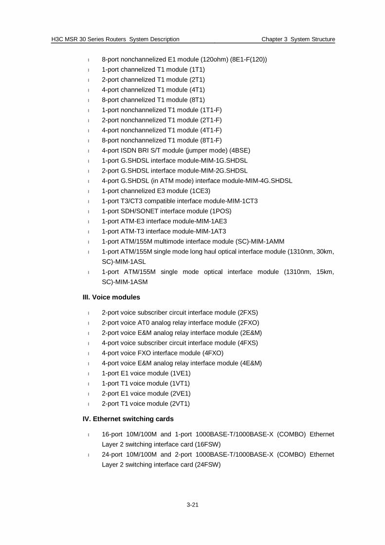
l 8-port nonchannelized E1 module (120ohm) (8E1-F(120)) l 1-port channelized T1 module (1T1) l 2-port channelized T1 module (2T1) l 4-port channelized T1 module (4T1) l 8-port channelized T1 module (8T1) l 1-port nonchannelized T1 module (1T1-F) l 2-port nonchannelized T1 module (2T1-F) l 4-port nonchannelized T1 module (4T1-F) l 8-port nonchannelized T1 module (8T1-F) l 4-port ISDN BRI S/T module (jumper mode) (4BSE) l 1-port G.SHDSL interface module-MIM-1G.SHDSL l 2-port G.SHDSL interface module-MIM-2G.SHDSL l 4-port G.SHDSL (in ATM mode) interface module-MIM-4G.SHDSL l 1-port channelized E3 module (1CE3) l 1-port T3/CT3 compatible interface module-MIM-1CT3 l 1-port SDH/SONET interface module (1POS) l 1-port ATM-E3 interface module-MIM-1AE3 l 1-port ATM-T3 interface module-MIM-1AT3 l 1-port ATM/155M multimode interface module (SC)-MIM-1AMM l 1-port ATM/155M single mode long haul optical interface module (1310nm, 30km,
SC)-MIM-1ASL l 1-port ATM/155M single mode optical interface module (1310nm, 15km,
SC)-MIM-1ASM
III. Voice modules
l 2-port voice subscriber circuit interface module (2FXS) l 2-port voice AT0 analog relay interface module (2FXO) l 2-port voice E&M analog relay interface module (2E&M) l 4-port voice subscriber circuit interface module (4FXS) l 4-port voice FXO interface module (4FXO) l 4-port voice E&M analog relay interface module (4E&M) l 1-port E1 voice module (1VE1) l 1-port T1 voice module (1VT1) l 2-port E1 voice module (2VE1) l 2-port T1 voice module (2VT1)
IV. Ethernet switching cards
l 16-port 10M/100M and 1-port 1000BASE-T/1000BASE-X (COMBO) Ethernet Layer 2 switching interface card (16FSW)
l 24-port 10M/100M and 2-port 1000BASE-T/1000BASE-X (COMBO) Ethernet Layer 2 switching interface card (24FSW)

H3C MSR 30 Series Routers System Description Chapter 3 System Structure
3-22
V. Encryption module
l High performance network data encryption module (HNDE)
3.4.3 ESM Module
l High-performance network data encryption ESM module (ESM-ANDE) l Standard network data encryption ESM module (ESM-SNDE)
ESM module supports IPSec and by using hardware encryption expedites IP packet encryption. The use of hardware encryption/decryption and hashing operation allows the router to encrypt packets with high performance and reliability.
The encryption card is optional. On a router installed with an encryption card, the main control board functions to route IP packets and implement encryption-enabled VPN, while the encryption card functions to encrypt packets.
Table 3-31 Encryption card attributes
Attribute Description
Protocol IP sec
Hardware encryption algorithm Key algorithms: DES, 3DES, AES Authentication algorithms: HMAC-MD5-96, HMAC-SHA-1-96
3.4.4 VPM and VCPM Module
VPM (Voice Processing Module) functions to implement the encryption/decryption, EC and CNG of voices.
VCPM (Voice Co-Processing Module) processes the voice data in combination with VPM.
l Voice co-processing module RT-VCPM l 8-way voice processing module RT-VPM8 l 16-way voice processing module RT-VPM16 l 24-way voice processing module RT-VPM24 l 32-way voice processing module RT-VPM32

H3C MSR 30 Series Routers System Description Chapter 4 System Feature List and Performance Index
4-1
Chapter 4 System Feature List and Performance
Index
4.1 H3C MSR 30 Series Feature List
Table 4-1 H3C MSR 30 Series Feature List
Item Description
LAN protocol
l ARP (agent ARP, free ARP and authorization ARP)
l Ethernet_II l Ethernet_SNAP l VLAN-BASED PORT ISOLATE/VLAN
VPN/VOICE VLAN) l 802.3x l LACP (802.3ad) l 802.1p l 802.1Q l 802.1x l RSTP (802.1w) l MSTP (802.1s) l GVRP l PORT MUTILCAST suppression Network
interconnection
WAN protocol
l PPP and MP l PPPoE Client and PPPoE Server l FR and MFR l FR Fragment, FR Compress and FR over
IP l FRTS l ATM (IPA, IPoEoA, PPPoA and PPPoEoA) l DCC and Dialer Watch l HDLC l LAPB l X25 and X25 to TCP l X25 PAD, X25 Huntgroup and X25 CUG l DLSW (V1.0/2.0) l ISDN and ISDN Network l ISDN QSIG l MODEM
Network protocol IP service
l Fast forwarding (unicast/multicast) l TCP l UDP l IP Option l IP unnumber l Policy routing (unicast/multicast)
H3C MSR 30 Series Routers System Description Chapter 4 System Feature List and Performance Index
4-2
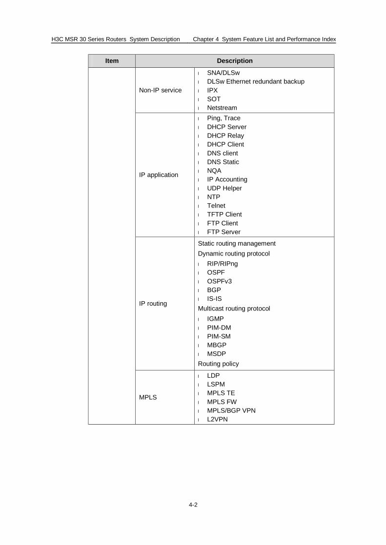
Item Description
Non-IP service
l SNA/DLSw l DLSw Ethernet redundant backup l IPX l SOT l Netstream
IP application
l Ping, Trace l DHCP Server l DHCP Relay l DHCP Client l DNS client l DNS Static l NQA l IP Accounting l UDP Helper l NTP l Telnet l TFTP Client l FTP Client l FTP Server
IP routing
Static routing management Dynamic routing protocol l RIP/RIPng l OSPF l OSPFv3 l BGP l IS-IS Multicast routing protocol l IGMP l PIM-DM l PIM-SM l MBGP l MSDP Routing policy
MPLS
l LDP l LSPM l MPLS TE l MPLS FW l MPLS/BGP VPN l L2VPN

H3C MSR 30 Series Routers System Description Chapter 4 System Feature List and Performance Index
4-3
Item Description
IPv6
l Basic IPv6 functions l IPv6 ND l IPv6 PMTU l IPv6 FIB l IPv6 ACL l IPv6 transition technology l NAT-PT l IPv6 tunnel l 6PE l IPv6 routing l IPv6 static routing management l Dynamic routing protocol l RIPng l OSPFv3 l IS-ISv6 l BGP4+ l Multicast routing protocol l MLD l PIM-DM l PIM-SM l PIM-SSM
Port security l PPPoE Client & Server l PORTAL l 802.1x
AAA l Local authentication l Radius l HWTACACS
Firewall l ASPF l ACL l FILTER
Data security
l IKE l IPSec l Encryption card l Portal
Network security
Others
l L2TP l NAT/NAPT l PKI l RSA l SSH V1.5/2.0 l SSL l URPF l GRE
Reliability VRRP Backup center

H3C MSR 30 Series Routers System Description Chapter 4 System Feature List and Performance Index
4-4
Item Description
Layer 2 QoS
l SP l WRED (Port) l CAR l LR l Flow-base QOS Policy l Port-Based Mirroring l Flow Redirect l Priority Mapping l Port Trust Mode l Port Priority l Flow Filter l FlowControl&Backpressure l ACL
Traffic policying l CAR (Committed Access Rate) l LR (Line Rate)
Congestion management l FIFO, PQ, CQ, WFQ, CBQ and RTPQ
Congestion avoidance l WRED/RED
Traffic shaping l GTS (Generic Traffic Shaping)
QOS
Other QOS technologies
l FR QOS l MPLS QOS l MP QoS/LFI l cRTP/IPHC l ATM QOS l Sub interface QOS
Interface
l FXS l FXO l E&M l VE1/VT1
Signaling
l R2 l DSSI l Q.sig l Digital E&M
H.323 l H.225 l H.245
GK Client l GK Client
SIP l SIP
Voice
Codec
l G.711A law l G.711U law l G.723R53 l G.723R63 l G.729a l G.729R8

H3C MSR 30 Series Routers System Description Chapter 4 System Feature List and Performance Index
4-5
Item Description
Media Process l RTP/cRTP l IPHC l Voice Backup
FAX l FAX
Others l Voice RADIUS
Network management
l SNMP V1/V2c/V3 l MIB l SYSLOG l BIMS l RMON
Local management
l Command line l File system l auto-config l Dual Image Maintainabilit
y
User access management
l Console port l AUX port l TTY port l Telnet (VTY) l SSH l FTP l X25 PAD l XMODEM
For Comware features in the above table, refer to Comware V5 System Description
4.2 System Performance Index of H3C MSR 30 Series Routers
Table 4-2 System performance index of H3C MSR 30 series routers
Argument MSR 30-20 MSR 30-40/30-60
Packet processing capacity 180Kpps 220Kpps
Frame delay (64Bytes in the maximum of 100% traffic) < 0.1 ms < 0.1 ms
Frame loss rate (in the maximum of 110% traffic) < 10% < 10%
System startup time <120s <120s

H3C MSR 30 Series Routers System Description Chapter 5 Applications and Solutions
5-1
Chapter 5 Applications and Solutions
5.1 Network Application of Integrated Multiple Services
By leveraging pinch cards directly embedded in the main board and the new Comware V5 software platform from Huawei-3Com, the next generation of MSR series routers provides a full set of services integrating switching, voice and security applications in order to implement a variety of services applications cost-effectively and conveniently, including voice applications.
Figure 5-1 Integrated multiple services network
5.2 Network Application of Comprehensive Services in Enterprises
For small- and medium-sized businesses (SMBs), a full series of MSR 20/30/50 routers can be used for comprehensive services networks, where MSR 50 series routers serve as the core in enterprises and MSR 20/30 series routers as the access devices in branches. A variety of services are available, including data, video, voice and fax. For large or ultra large enterprises, H3C NE series high-end and core routers are used as the core in enterprises and MSR 30/50 series routers as the access devices on the edge and aggregation layer in branches. The following illustrates a typical network application where MSR 50 series routers serve as the core.
H3C MSR 30 Series Routers System Description Chapter 5 Applications and Solutions
5-2
Headquarters
BranchOfficeH3C MSR 20/30 H3C MSR 20/30
H3C MSR 50
PBX
PBX PBX
Client Client
Client
PC
PC
PC
Sever MCU
E1
Carrier Network
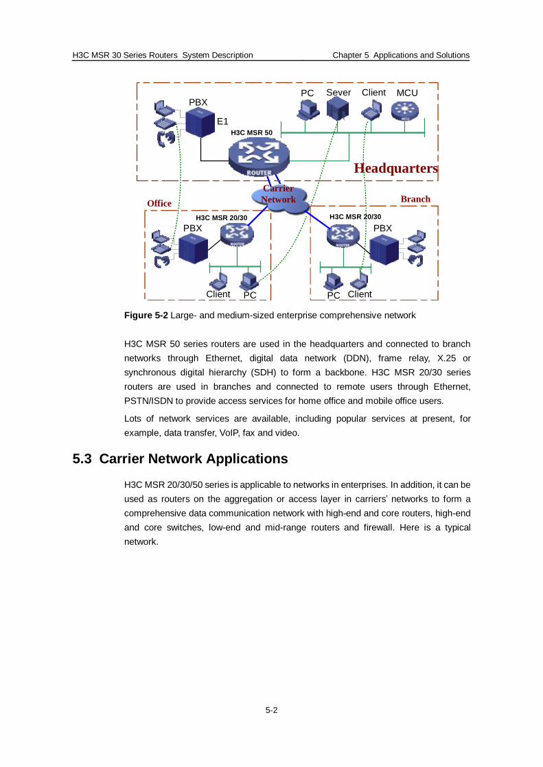
Figure 5-2 Large- and medium-sized enterprise comprehensive network
H3C MSR 50 series routers are used in the headquarters and connected to branch networks through Ethernet, digital data network (DDN), frame relay, X.25 or synchronous digital hierarchy (SDH) to form a backbone. H3C MSR 20/30 series routers are used in branches and connected to remote users through Ethernet, PSTN/ISDN to provide access services for home office and mobile office users.
Lots of network services are available, including popular services at present, for example, data transfer, VoIP, fax and video.
5.3 Carrier Network Applications
H3C MSR 20/30/50 series is applicable to networks in enterprises. In addition, it can be used as routers on the aggregation or access layer in carriers’ networks to form a comprehensive data communication network with high-end and core routers, high-end and core switches, low-end and mid-range routers and firewall. Here is a typical network.

H3C MSR 30 Series Routers System Description Chapter 5 Applications and Solutions
5-3
Figure 5-3 Network application in carriers’ networks or large networks
H3C NE series high-end and core routers are used in the core to form a backbone ring network. NE40, NE16E and NE08E can function as core routers. 155M POS or GE links are used in the backbone. At the same time, dual devices are used in each stage for higher reliability of backbone.
MSR 20/30/50 series routers are used on the aggregation layer and the access layer to access the networks on the corresponding layers. These devices use 155M, 100M Ethernet and 2M lines as their communication links.
Other high-end, mid-range and low-end devices from H3C are used as switches and firewall in the network.
5.4 IPv6 Network Application
The next generation of MSR series routers provides a full support for IPv6, one of its important features. To protect user investments and the compatibility with the existing IPv4 networks, IPv4 is also supported. With dual-stacking technology, the next generation of MSR series routers can ensure the concurrent operation of pure IPv4 devices and pure IPv6 devices in a network properly. The following figure is an IPv6 network application.

H3C MSR 30 Series Routers System Description Chapter 5 Applications and Solutions
5-4
IPv4 Internet
IPv6 Internet
DDN/ATM/FR
DSTN/ISDN
Branch(IPv4)
Dial-in network(IPv4)
Branch stack
IPv4 host IPv6 host
Dual-stacking server
IPv6 over IPv4
IPv6 / IPv4 hybrid linkIPv6 to IPv4 tunnelIPv6 linkIPv4 link
NAT-PT DSTMHeadquarters
Dual-stacking server
Figure 5-4 IPv6 network
MSR 50 series routers with IPv6/IPv4 dual-stacking technology are used in the headquarters and MSR 20/30 series routers are used in branches. You can use IPv4 independently or IPv6/IPv4 dual-stacking technology for networking. For network communications from IPv6 to IPv4, tunneling also can be used to realize seamless communications between IPv6 and IPv4 networks.
5.5 MPLS VPN Network Application
The next generation of MSR series routers supports MPLS VPN technology that can be used to build a network. H3C NE series high-end and core routers and MSR 50 series routers are used in the headquarters; H3C MSR 20/30 series routers are used in branches or partners’ networks. . NE series routers can function as P devices and MSR 50 series routers can function as PE devices to access the networks in branches. More than one VPN can be built for different services so as to guarantee security between them.
The following figure is a typical network.

H3C MSR 30 Series Routers System Description Chapter 5 Applications and Solutions
5-5
Figure 5-5 MPLS VPN network application
H3C NE series high-end and core routers are used as P devices in the headquarters. MSR 50 series routers are also used as PE devices to access the service networks of branches. With VPF technology, diverse services in branches are partitioned into different VPN networks through PE devices, guaranteeing the security and reliability of services.
MSR 20/30 series routers are used in branches to connect to MSR 50 series routers in the headquarters. Different services are separated through physical networks in branches. When there are many services in a physical network, the VRF feature of MSR 50 can realize logical separation of service networks.
You can use different ways to build tunnels for MPLS VPN services. Using MPLS TE tunnel to carry VPN services is of great benefits in many aspects. As a result, VPN services have superior security and reliable QoS guarantee. Additionally, carriers can customize MPLS TE tunnels with different features to meet VPN user requirements.
5.6 Network Application of Voice Services
The next generation of MSR series routers provides mainstream voice communication protocols like H.323 and SIP for a variety of voice services such as emergency call/help in power off/dial-in policy/fax/E-PHONE and a variety of voice interfaces such as FXS/FXO/VE1/VT1/E&M.
By leveraging an extensible structure, the next generation of MSR series routers allocates DSP resources consistently for higher DSP resource utilization, higher access density and local TDM switching. On the one hand, it provides qualified voice

H3C MSR 30 Series Routers System Description Chapter 5 Applications and Solutions
5-6
services. On the other hand, it avoids DSP resource occupation of local calls and saves DSP resources.
If you do not need voice services, MSR series provide flexible pinch card design to help save investments.
Figure 5-6 Voice services network
5.7 Network Application of Security Services
By inheriting all security features of previous versions of Comware software platform and supporting the routing and switch convergence feature of Comware V5 version, the next generation of MSR series routers allows to implement a secure VPN network through the existing Internet.
MSR 50 series routers are used as the core in enterprises and MSR 20/30 series routers are used as the access devices in branches. By combining robust service performances of MSR 30/50 series routers, enterprises can implement a qualified and multi-services comprehensive security network.
The following is a typical security network application of MSR 30/50 series routers.

H3C MSR 30 Series Routers System Description Chapter 5 Applications and Solutions
5-7
L2TP+IPSEC
Figure 5-7 Security network
Combined with robust performances of security services, MSR 50 routers are used in the headquarters as the application security service gateway. At the same time, it can function as an external firewall to protect the security of the Intranet. With VLAN separation and 802.1x functions, you can carry out security access authentication for the Intranet users directly through switching modules.
MSR 30 routers are used in branches as access to VPN and IPSec. At the same time, MSR 30 routers can function as VPN access gateway to provide VPN access for SOHO and mobile employees.
5.8 Network Application of Integrated Routing and Switch
The next generation of MSR series routers has realized an integrated design and implementation in terms of software and hardware. You can use all features of routers and switches smoothly. For small- and medium-sized businesses (SMBs), a full series of MSR 20/30/50 routers can be used for comprehensive services networks, where MSR 50 series routers serve as the core in enterprises and MSR 20/30 series routers as the access devices in branches. A variety of services are available, including data, video, voice and fax. For large or ultra large enterprises, H3C NE series high-end and core routers are used as the core in enterprises and MSR 30/50 series routers as the access devices on the edge and aggregation layer in branches. The following illustrates a typical network application where MSR 50 series routers serve as the core.

H3C MSR 30 Series Routers System Description Chapter 5 Applications and Solutions
5-8
Figure 5-8 Integrated routing and switch network
H3C MSR 50 series routers are used in the headquarters and connected to branch networks through Ethernet, digital data network (DDN), frame relay, X.25 or synchronous digital hierarchy (SDH) to form a backbone.
H3C MSR 20/30 series routers are used in branches and connected to remote users through Ethernet, PSTN/ISDN to provide access services for home office and mobile office users.
Lots of network services are available, including popular services at present, for example, data transfer, VoIP, fax and video.