determination of flow patterns by image analysis of a
TRANSCRIPT

2017 NETL Workshop on Multiphase Flow Science
Determination of Flow Patterns by Image Analysis of a
Rectangular Spouted Bed
By: Jingsi Yang, Steven Rowan,
Ronald Breault, Justin Weber.Fluid Particle Science and Engineering Group
August 9, 2017
1

2Contents
• Introduction
• Experimental systems
• Current research objectives:
Flow pattern observation
Image preliminary processing
Bed height determination
Bed expansion ratio
• Future focuses:
Jet size and voidage determination
• Conclusions

3Introduction-Spouted phenomenon
Fountain
Bed surface
Annulus
Spout
Gas inlet
For a vessel filled with coarse particles, when the gas isinjected vertically through a centrally located opening, theresulting high-velocity jet leads to a stream of particlesrising rapidly in a hollowed central core within the bed ofparticles. Particles carried above the bed surface, rain backon the annular region between the hollowed core andthe column wall.
A composite of a dilute phase central core with upward-moving solids entrained by a concurrent air flow and adense phase surrounding with downward particle flow.

4
Hydrodynamics in spouted beds have been characterized extensively by optical fiber systems andpressure fluctuation analysis. With the development of high speed video cameras and imaginganalysis methods, an alternative method based on image analysis was proposed to study thehydrodynamics in a rectangular spouted bed in this study.
Cavity formation Internal spout development Onset of external spout
Increasing fluid flow rate
Introduction-Evolution of typical spouting process

5Experimental systems-Spouted bed & visualization apparatus
Spouted bed
Images Analysis Diffusion
Panel
30.2 mm
Backup light
Video Camera
Dequ = 9.6 mm Dequ = 12.7 mm
Air
Spouted bed
Filter
75 ° Cone
Slotted nozzle
ΔP3
ΔP2
ΔP1
101.6 mm
30.2 mm
Pressure transducer
3.8 mm
19.1 mm 25.4 mm
25.4 mm
6.6 mm
19.1 mm
25.4 mm
25.4 mm

6Flow pattern observation
Alumina
Nylon
Static
Static
Expansion External spoutingBubble development
Jet development External spouting Increasing gas flow rate

7Image preliminary processing
(a)
(b)
(c)
(d)
(e)
Preprocessing for the following processes
Image (c) Image (d)
Logical operation
Image (e)

8

9
Original Cropped grayscale Binary Extracted binary
Bed height determination

10
0 150 300 450 600 750 900100
120
140
160
180
200
220
240
260
Deriv
ative
of a
vera
ge in
tens
ity (-
)
Pixels (-)
Average intensity 2nd Derivative of average intensity
-20
0
20
40
60
80
100
Aver
age
inte
nsity
(-)
Bed surface
Bed bottom
Bed surface
Bed bottom
Bed height
Bed height determination-Demonstration and examples

11

12
0.0 0.4 0.8 1.2 1.60.070
0.075
0.080
0.085
0.090
Alumina0.00962 m nozzle0.0762 m Static bed height
Bed
heig
ht (m
)
Superficial gas velocity (m/s)0.0 0.2 0.4 0.6 0.8 1.0 1.2 1.4 1.6
0.0
0.3
0.6
0.9
1.2
1.5 Bed pressure drop Bed expansion ratio
Superficial gas velocity (m/s)Be
d pr
essu
re d
rop
(KPa
)
0.95
1.00
1.05
1.10
1.15
1.20
Bed expanded
Spouted bed
Alumina 0.00962 m nozzle
Bed
exp
ansio
n ra
tio (-
)
0.0762 m Static bed height
Internal spout External spout
Packed bed
Minimum spouting velocity
External spouting velocity
① ② ③
Bed height determination-Demonstration and examples

13
① ② ③

14
0.0 0.5 1.0 1.5 2.00.95
1.00
1.05
1.10
1.15
1.20
1.25Alumina0.00962 m nozzle
Bed
expa
nsio
n ra
tio (-
)
Superficial gas velocity (m/s)
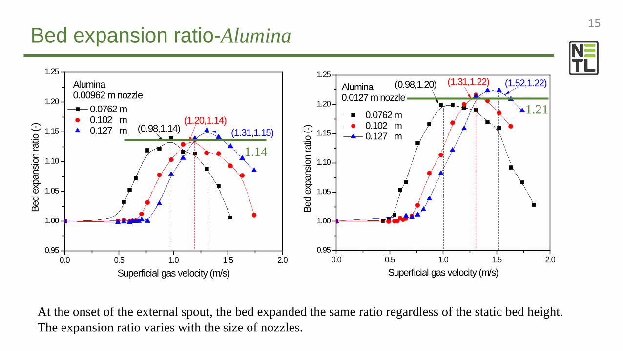
0.0762 m 0.102 m 0.127 m (0.98,1.14) (1.31,1.15)
(1.20,1.14)
0.0 0.5 1.0 1.5 2.00.95
1.00
1.05
1.10
1.15
1.20
1.25Alumina0.0127 m nozzle
Bed
expa
nsio
n ra
tio (-
)
Superficial gas velocity (m/s)
0.0762 m 0.102 m 0.127 m
(0.98,1.20) (1.52,1.22)(1.31,1.22)
15Bed expansion ratio-Alumina
1.14
1.21
At the onset of the external spout, the bed expanded the same ratio regardless of the static bed height.The expansion ratio varies with the size of nozzles.

16Bed expansion ratio-Nylon
0.0 0.5 1.0 1.5 2.0 2.50.95
1.00
1.05
1.10
1.15
1.20
1.25
1.30
1.35
1.40
(1.52,1.32)
(1.41,1.32)
Nylon0.00962 m nozzle
Bed
expa
nsio
n ra
tio (-
)
Superficial gas velocity (m/s)
0.0762 m 0.102 m 0.127 m
(1.09,1.34)
1.32
0.0 0.5 1.0 1.5 2.0 2.50.95
1.00
1.05
1.10
1.15
1.20
1.25
1.30
1.35
1.40Nylon0.0127 m nozzle
Bed
expa
nsio
n ra
tio (-
)
Superficial gas velocity (m/s)
0.0762 m 0.102 m 0.127 m
(1.63,1.31)
(1.85,1.31)
(1.20,1.33)
1.32
At the onset of the external spout, the bed expanded the same ratio regardless of the static bed heights and nozzle sizes.

17Bed expansion ratio-The effect of nozzle size
The effect of nozzle size on the bed expansion ratio of Alumina is more significantly than that of Nylon.
1.0
1.1
1.2
1.3
1.4
1.0
1.1
1.2
1.3
1.4
0.0 0.5 1.0 1.5 2.0 2.5
1.0
1.1
1.2
1.3
1.4
H0= 0.0762 m 0.00962 m 0.0127 m
Nylon
H0= 0.102 m
Bed
expa
nsio
n ra
tio (-
)
H0= 0.127 m
Superficial gas velocity (m/s)
1.001.051.101.151.201.25
1.001.051.101.151.201.25
0.0 0.5 1.0 1.5 2.00.951.001.051.101.151.201.25
H0= 0.0762 m Alumina 0.00962 m 0.0127 m
H0= 0.102 m
Bed
expa
nsio
n ra
tio (-
)
H0= 0.127 m
Superficial gas velocity (m/s)
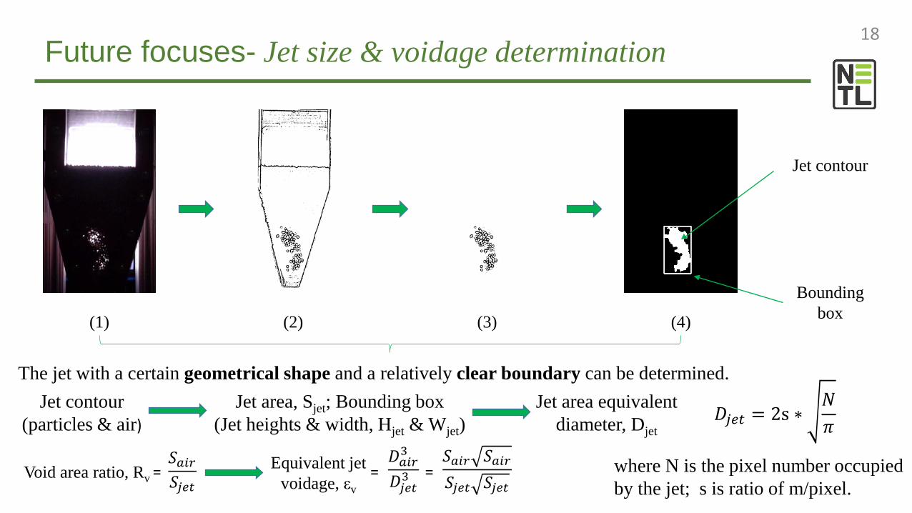
18Future focuses- Jet size & voidage determination
The jet with a certain geometrical shape and a relatively clear boundary can be determined.
(1) (2) (3) (4)
Jet contour
Bounding box
Jet contour (particles & air)
Jet area, Sjet; Bounding box(Jet heights & width, Hjet & Wjet)
Jet area equivalent diameter, Djet
𝐷𝐷𝑗𝑗𝑗𝑗𝑗𝑗 = 2s ∗𝑁𝑁𝜋𝜋
where N is the pixel number occupied by the jet; s is ratio of m/pixel.
Void area ratio, Rv𝑆𝑆𝑎𝑎𝑎𝑎𝑎𝑎𝑆𝑆𝑗𝑗𝑗𝑗𝑗𝑗
= Equivalent jet voidage, εv
𝑆𝑆𝑎𝑎𝑎𝑎𝑎𝑎 𝑆𝑆𝑎𝑎𝑎𝑎𝑎𝑎𝑆𝑆𝑗𝑗𝑗𝑗𝑗𝑗 𝑆𝑆𝑗𝑗𝑗𝑗𝑗𝑗
=𝐷𝐷𝑎𝑎𝑎𝑎𝑎𝑎3
𝐷𝐷𝑗𝑗𝑗𝑗𝑗𝑗3=

19Conclusions
Based on a systematic of image processing
procedures, an alternative method was proposed to
study the hydrodynamics in a rectangular spouted
bed.
Different flow patterns were observed:
Flow regime transformation was complicated;
Under the same static bed height, the flow
regime was changed with the increase of
superficial gas velocity.
Bed expansion ratio indicated the external spout
velocity, which was helpful to determine flow
regime.
High speed video
Original images
Threshold & logical operations
Jet size/penetration depth
Typical flow pattern
Bed expansion ratio
Jet Voidage
Video extraction
Adaptive threshold & blank image &
Mask
Calculation of jet area
Bed height calculation
Calculation of air/void area
in the jet
Polygon ROI cropping
Dilation & erosion
Denoising
Self-defined aglorism
Jet contour

20Conclusions
The variation of bed expansion ratios with superficial gas velocity were shown for Alumina and
Nylon particles using two different nozzle sizes (0.00962 m and 0.0127 m):
At the onset of the external spout, the bed expanded the same ratio regardless of the static
bed heights under the same nozzle size for both particles;
Comparing to Nylon, the bed expansion ratio of Alumina at the onset of the external spout
was influenced more significantly by the nozzle size.
Future focuses:
Determination of jet sizes and voidage, and fountain height by applying image analysis;
Different parameters such as cone angle, property of bed materials;
Flow regime map construction.

21Acknowledgements
Dr. Ronald Breault (Mentor);
Justin Weber (Research Advisor);
Steve Rowan;
Michael Bobek;
Nicholas Hillen;
Sam Bayham;

22