determination of magnetic hysteresis with the fahy simplex … · 2012-06-22 · hysteresis loop by...
TRANSCRIPT

U. S. DEPARTMENT OF COMMERCE NATIONAL B UREAU OF STANDARDS
RESEARCH PAPER RP845
Part of Journal of Research of the National Bureau of Standards, Volume 15, November 1935
DETERMINATION OF MAGNETIC HYSTERESIS WITH THE FAHY SIMPLEX PERMEAMETER
By Raymond L. Sanford and Evert G. Bennett
ABSTRACT
An attachment for the Fahy Simplex permeameter is described by which the H-coil can be quickly rotated end for end. By means of this attachment, values of magnetizing force, H, corresponding to points on a hysteresis loop, can be attained with as high precision as could be attained previously only for points on the normal induction curve. By the use of this attachment, smoother curves are obtained in less time than can be done with the original arrangement.
CONTENTS Page
r. Introduction _ _ _ _ _ _ _ _ _ _ _ _ _ _ _ _ _ _ _ _ _ _ _ _ _ _ _ _ _ _ _ _ _ _ _ _ _ _ _ _ _ _ _ _ _ _ _ _ _ 517 II. Description of the apparatus__ ________ _______ ___________ ___ ____ 518
III. Experimental data _ _ __ _ _ __ __ _ _ _ _ _ ___ _ _ _ _ _ _ _ _ _ _ _ _ _ _ __ _ _ _ _ _ _ _ _ _ _ 520
I. INTRODUCTION
The Fahy Simplex permeameter 1 is a very satisfactory instrument for the determination of normal induction and hysteresis data for ordinary magnetic materials. Its principal advantages are simplicity and convenience of operation and its ability to indicate the average properties of inhomogeneous materials. 2 However, in common with other methods in which values both of magnetic induction B, and of magnetizing force H, are obtained in terms of deflections of a ballistic galvanometer, the apparatus in its original form does not give hysteresis data with as high precision as can be realized in measurements of normal induction. The reason for this is that points on a hysteresis loop are determined by taking the algebraic difference between the value of B or H corresponding to the tip of the loop and the change observed when the magnetizing current is suddenly reduced from the maximum value to some lower value in either the same or opposite direction. The lack of precision is particularly conspicuous in the measurement of H, especially for the part of the loop in the neighborhood of the coercive force He. By reference to figure 1 it can be seen that a determination of the value of HC1 for instance, involves taking the difference between the two quantities Hm and (Hm+He), each of which is large relative to the value of He. It is obvious that even a small experimental error in the observed values of Hm and (Hm+I{) may lead to a relatively large percentage error in the value of He taken as the difference between them.
1 Fahy, Chern. Met. Eng. 19,339 (1918). 2 Sanford, Performance of the Fahv Simplex Permeameter, DS J. Research 4, 703 (1930) RP174.
517

518 Journal of Research of the National Bureau of Standards [Vol . 15
The present investigation was undertaken to find out whether or not it would be feasible to determine the values of H for points on a hysteresis loop by direct measurement instead of by taking differences as indicated above. It was found possible to do this by mounting the H-coil so that it can be quickly turned end for end between the H-blocks by rotating it about a vertical axis through its center. In this way values of H for points on a hysteresis loop can be determined with a precision as great as that formerly attainable only for points on the normal induction curve.
II. DESCRIPTION OF THE APPARATUS
The permeameter with the new H-coil in place is shown in figure 2. A brass framework holds the iron end-blocks in proper position and carries the bearings for the vertical shaft through the middle of the II-coil. It was necessary to make the new end-blocks slightly longer than the original ones to provide for clearance between the magnet-
B
BMI----========~:::::::==-I
- H -He
FIGURE I.-Upper half of a typical hysteresis loop.
izing coil and the H-coil when the latter is rotated. A pinion at the upper end of the vertical shaft engages with a rack which also engages with a smaller pinion on the shaft of a small series wound-motor mounted at the back of the permeameter.
Two stops similar to ordinary switch clips limit the rotation of the coil to 180°. These stops receive a brass blade mounted on the H-coil near one end and can be adjusted to regulate the amount of friction. In order to reduce the impact on the apparatus to a minimum, the motor current is cut off before the stroke is completed by means of an automatic switch mounted on top of the apparatus. This switch is actuated by a bakelite block attached to the rack and can be adjusted to cut off the current at any desired point during the stroke. When the switch and stops are properly adjusted, the H-coil can be quickly rotated end for end between the end-blocks without producing an appreciable jar on the apparatus. Connection to the coil is made by means of flexible leads.

Journal of Research of the National Bureau of Standards Research Paper 845
FrGU HE 2.- P enneameteT lei/ II Totaling H- coil attached.

Sanford] Bennett Hysteresis With Fahy Simplex Permeameter 519
A diagram of connections is given in figure 3. A source of d-c power is connected at G. The reversing switch F is located at the control table and is operated by the observer. The contacts on the automatic cut-off switch A, are operated by the bakelite block mounted on the rack and are so connected that the armature circuit of the motor is complete only when F is closed in the right direction. When this is done, the motor operates to rotate the H-coil about its vertical axis. At the proper time, the contact at A is opened, thus cutting off the current and allowing the stroke to be completed by momentum. The movement of the block also permits the other contact at A to close so that the coil can be rotated in the opposite direc-
E
F ...., ...... _------,
1 G
FIGURE 3.-Diagram of connections.
tion by reversing switch F. A capacitor E absorbs the inductive surge caused by openin~ the motor field circuit. B represents a group of plugs and jacks for dIsconnecting the cut-off switch when the apparatus is to be removed from the permeameter. The apparatus is interchangeable with the regular end-blocks and H-coil.
The cycle of operations to determine a point on a hysteresis loop is as follows. The magnetizing current is set to give the desired Hm and reversed a sufficient number of times to bring the specimen to a cyclic condition. The value of Hm is determined either by reversal of the magnetizing current or by rotating the H-coil. The value of B is obtained by reversal of the current. After the values of Band H
22381-35-6
-~-~------~-~~ ---.-----------~-----~-----------
520 Journal oj Research oj the National Bureau oj Standards [Vol. 15
at the tip are established, the current is reduced in the regular way with the galvanometer connected to the B-coil. The value obtained by subtracting the observed change from Bm previously determined is the required value of B. After the current has been reduced to the required value, the galvanometer is connected to the H-coil and the coil is rotated. For this determination, the galvanometer sensitivity is adjusted to a suitable value higher than that used for the determination of Hm. Several check readings can be taken without reestablishing cyclic condition as is necessary when the regular method is used. In this way the value of H corresponding to the desired point on the hysteresis loop can be determined directly, with a precision equal to that obtained in the measurement of a similar value on the normal induction curve.
III. EXPERIMENTAL DATA
Before proceeding with the construction of the apparatus, experiments were made to determine the effect of the various changes in dimensions necessitated by mechanical conditions. The principal changes were (1) an increase in the length of the iron end-blocks, (2) a slight increase in the distance between the ends of the H-coil and the end-blocks, and (3) a gap of approximatelY}6 inch at the middle of the H-coil to permit the insertion of the shaft. Each of these modifications caused a definite change in the proportionality factor between the galvanometer deflection and the value of H. However, the factor as empirically determined by reference to a standard bar of known properties was found to be practically constant throughout the range of the instrument. No effect due to stray field from the motor could be detected.
As a final check, normal induction and hysteresis data were determined for a number of standard bars and these were compared with data on the same bars obtained by the permeameter in its original form. Figure 4 is typical of the results obtained. The full lines are the curves obtained with the new apparatus and the points were obtained with the permeameter in its original form. The same order of agreement was obtained for the other bars. From these results it was concluded that no appreciable change in accuracy is produced by substituting the new apparatus for the original H-coil.
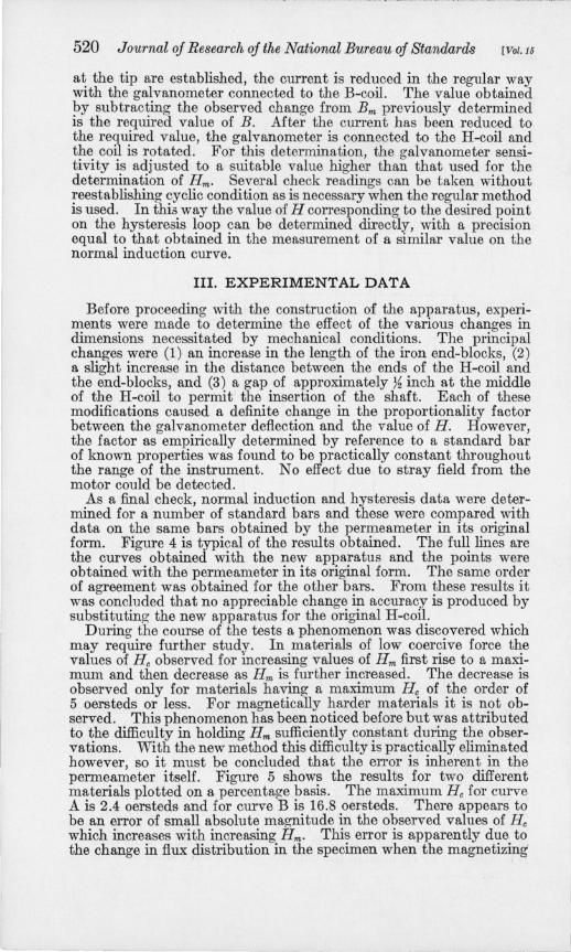
During the course of the tests a phenomenon was discovered which may require further study. In materials of low coercive force the values of He observed for increasing values of Hm first rise to a maximum and then decrease as Hm is further increased. The decrease is observed only for materials having a maximum He of the order of 5 oersteds or less. For magnetically harder materials it is not observed. This phenomenon has been noticed before but was attributed to the difficulty in holding Hm sufficiently constant during the observations. With the new method this difficulty is practically eliminated however, so it must be concluded that the error is inherent in the permeameter itself. Figure 5 shows the results for two different materials plotted on a percentage basis. The maximum He for curve A is 2.4 oersteds and for curve B is 16.8 oersteds. There appears to be an error of small absolute magnitude in the observed values of He which increases with increasing Hm. This error is apparently due to the change in flux distribution in the specimen when the magnetizing'

Sanford] Bennett Hysteresis With Fahy Simplex Permeameter
o H , OERSTEDS
-25 o 25 50
~ Z I.&J U a: I.&J D.
o J:
FIGURE 4.-Agreement between new apparatus and original H-coil .
Curves represent results with new apparatus. Points show results with original H·coil .
85W---~~--~~--~----~----~----~
H"" OERSTEDS 8 0 LI---I---.JL--__ ---.JL.....!!!...:..----l ____ ---l ____ ---l ____ ---1
521
o 50 100 150 200 250 300 FIGURE 5.-0bserved variation of He with Hm for two di:fforent materials.
Curve A, Max H.=2.4 oersteds. Curve B, Max H.=16.8 oersteds.

522 Journal oj Research oj the National Bureau oj Standards [Vol. 16
current is reduced from the maximum value to some other value corresponding to a point on the hysteresis loop. Observations have shown that both the radial and longitudinal distribution in the specimen for a point on the loop differ from the corresponding distribution for points on the normal induction curve. Fortunately, the magnitude of the effect is within the experimental error of the original method and therefore can usually be ignored.
Practical experience with the apparatus has demonstrated several advantages. It is possible, for instance, to determine whether or not a specimen has been brought by demagnetization to a symmetrically cyclic condition by checking for equality in the value of H for both positive and negative directions of the maf!;netizing current. The effect of magnetic viscosity in a specimen whICh sometimes produces a "double kick" of the galvanometer is eliminated by measuring H after the change in induction is completed. It is easier with the new apparatus to measure He from a relatively high tip because less care is required in maintaining a constant value of Hm. This is especially true for materials having low values of coercive force. In addition to these advantages, smoother hysteresis loops can be obtained in less time than is possible with the original H-coil arrangement.
WASHINGTON, August 28, 1935.