determination of performance measuring...
TRANSCRIPT
Research ArticleDetermination of Performance Measuring Parameters of anImproved Dual Paraboloid Solar Cooker
Suhail Zaki Farooqui1,2
1US-Pakistan Center for Advanced Studies in Energy, University of Engineering & Technology, Peshawar, Pakistan2Faculty of Engineering Sciences, PNEC, National University of Sciences & Technology, Islamabad, H.I. Rahamatullah Road,Karachi 75350, Pakistan
Correspondence should be addressed to Suhail Zaki Farooqui; [email protected]
Received 9 May 2017; Revised 15 June 2017; Accepted 20 June 2017; Published 7 August 2017
Academic Editor: Xinhai Xu
Copyright © 2017 Suhail Zaki Farooqui. This is an open access article distributed under the Creative Commons Attribution License,which permits unrestricted use, distribution, and reproduction in any medium, provided the original work is properly cited.
An experimental investigation into the performance evaluation of an improved dual reflector foldable paraboloid solar cooker hasbeen reported, along with its energy and exergy analysis. The best attribute of this lightweight and low-cost solar cooker is its highperformance coupled with the ease of handling. The cooker utilizes two paraboloid reflectors made out of Mylar-coated fiberglassdishes, each having a diameter of 90 cm and focal length of 105 cm. The total intercepted radiation energy is 1.08 kW understandard test conditions. Stagnation temperatures of up to 330°C and cooking temperatures of up to 290°C have been attainedwith load. Altogether, 9 experiments have been performed with and without load. Loaded tests have been conducted with waterand vegetable oil. Results indicate an average cooking power of 485W, peak exergy gain of 60.53W, quality factor of 0.077, anda high product of temperature difference gap at half peak power to peak power of 4364.33W·K. The maximum exergy outputpower attained was 70W, while maximum exergy efficiency was 8–10%. All performance measuring parameters indicate that itis a high performance solar cooker for rural and urban communities and is suitable for all types of oil- and water-based cooking.
1. Introduction
Development of more efficient and user friendly solarcookers is a high priority area, as cooking of food accountsfor a substantially large chunk of the total fuel consumptionon Earth. In case of the developing countries, this activityaccounts to over one-third of the total primary fuel con-sumption [1, 2]. Conversion of cooking to renewables hasthe potential of substantially reducing the fuel bills of manyenergy-deficient countries of the world, as well as reducingthe greenhouse gas emissions. Three broad types of solarcookers have been reported in the literature during the lastover half a century. Box-type solar cookers utilizing thegreenhouse effect to acquire the cooking temperatures areso far the most popular ones, due mainly to their simplicityand lower costs. However, they suffer from the main disad-vantage of approaching the maximum temperatures ofaround 120°C. Therefore, they are suitable only for water-based low temperature cooking [3, 4]. Oil-based high tem-perature cooking is not possible with these cookers. Parabolic
types are the second most common solar cookers. Typically,they utilize a parabolic reflector mounted near the ground,which focuses the reflected solar radiation onto a cookingpan placed at a height. Generally, these cookers acquire highcooking temperatures suitable for cooking all types of food.However, they suffer from a number of issues, including therequirement of frequent solar tracking, lack of maneuverabil-ity due to larger sizes and weights, and the splashes of oil andcurry falling onto the reflector, requiring frequent cleaningand adversely affecting its reflectivity. The third main typeof solar cookers are the vacuum tube-based cookers, aspresented by various authors [1, 3–7]. Though these cookersacquire high temperatures and are very efficient, they arecomplex to operate and expensive to manufacture.
Parabolic-type solar cookers have been offered in severalversions by a number of authors. Typically, these cookersacquire concentration ratios of up to 50 and temperaturesof up to 300°C [8]. With a spherical reflector, the first designwas proposed by Stam in 1961 [2]. It was the simplesttype of reflector, allowing the cooking vessel to be hung
HindawiInternational Journal of PhotoenergyVolume 2017, Article ID 9459531, 12 pageshttps://doi.org/10.1155/2017/9459531

from a tripod at a suitable focal point. However, due to thespherical shape of the reflector, the focus was not very good.A parabolic reflector-type cooker named as SK-14 wasinvented by Dr. Dieter Seifert [9, 10]. The focus of this cookerwas much better and sharper than the previous one. How-ever, it is very sensitive to even a slight change in the positionof the sun and hence it requires constant tracking. Due to itsdeeply curved parabolic reflectors, the focal point lies insidethe dish [11, 12]. Further, due to the usage of a single largedish, it occupies more space, making it difficult to carry fromone place to the other. Also, the frequent oil and currysplashes spoil the reflector surface, as the cooking utensilsare placed above the parabolic reflector. Making this type ofcooker requires advanced manufacturing facilities availableonly to large companies.
The Sheffler community solar cooker was invented byWolfgang Sheffler in 1986 [13, 14]. The Sheffler-type solarcookers utilize large flexible parabolic mirrors to concentratethe solar radiation inside a kitchen on a fixed point through aNorth-facing window, where high temperatures of up to1000°C are attainable to cook all types of food. The polardirectional controls of the parabolic mirrors are carried outthrough clockwork rotation at the rate of one revolutionper day. The reflector is made to change the shape of itsentire surface every few days to adapt itself to the changingdeclination angles of the sun. For these reasons, its design,manufacturing, and installation are complex. Further, itrequires heavy and robust permanent structure for its sup-port and installation needs shadow-free area throughoutthe year in the south direction. The requirement for capitalinvestment is also high. Some authors have also evaluatedthe compound parabolic reflectors which do not require solartracking for a few hours [15, 16]. However, these are notsuitable for use with solar cookers due to their bulky size,complex construction, and use of large quantities of thermalfluids, causing delayed heating.
In this paper, the design and working scheme of a dualreflector parabolic cooker has been described and experi-mentally tested with an aim to address the abovementioneddeficiencies noted in this class of cookers. A lightweightcooker with two foldable fiberglass parabolic reflectorscoated with Mylar sheet has been introduced. These attri-butes make it convenient to move the cooker from one placeto the other, operate at any desired place, and easily storeinside the home when not in use. A number of simplecontrols have been provided to change the inclination of eachindividual reflector, as well as the collective inclination ofboth the reflectors, in order to maintain the focused radiationfrom both the reflectors onto the cooking pan, with changingpositions of the sun on the sky. Further, sufficient separationhas been provided between the two reflectors to allow any oiland curry splashed from the cooking pan to fall onto theground, rather than damaging the reflector surfaces. Supportfor the cooking pan has been kept separate to allow easymaneuverability of the cooker and to prevent shaking of thecooking utensils, while the reflective mirrors are adjusted.
Several experiments have been conducted without loadand with load of 4 kg of water, as well as vegetable oil toextract the various performance measuring parameters. The
experimental results are analyzed in each case for determin-ing the first and second figures of merit, cooking power,energy and exergy efficiencies, and the quality factor ofthe cooker.
The first figure of merit F1 measures the optical efficiencyof the cooker per unit heat loss factor. This is measured bydividing the difference of the maximum temperature attainedby the unloaded bottom of the cooker with the ambient airtemperature to the average solar radiation intensity duringexperiment. The second figure of merit F2 gives an indicationof heat transfer from the absorbing base to the water insidethe cooker. It is evaluated in the presence of full load, as theproduct of heat gained by water and F1 per unit aperture areaper unit time per unit temperature. The cooking power is theheat gained by the water inside the cooker per unit time.Energy efficiency of the cooker is evaluated as the heat gainedby the water inside the cooker divided by the solar radiationenergy intercepted by the cooker collector during a giventime. The exergy efficiency measures the potential of thecooker to extract the solar radiation energy. This is obtainedby dividing the exergy output of the cooker by the exergyinput. The exergy input and output are evaluated by record-ing the ambient air and water temperatures and solarradiation intensity after periodic intervals of time, whileconsidering the water content, aperture area of the cooker,and the temperature of the surface of the sun, using formulasdescribed in (4) and (5). The quality factor of the cooker isdetermined by dividing the peak exergy gain of the cookerwith the exergy loss (the difference between exergy inputand output) at that instant of time. The peak exergy gainis obtained by plotting the exergy output versus the tem-perature difference of water with the ambient air. Thecurve is fitted with a second order polynomial, and peakis determined.
2. The Optical Scheme of the Dual ParaboloidReflector
A paraboloid reflector is defined to provide a sharp focus tothe rays of light reflected from its surface, when the incidentlight consists of rays parallel to the axis of the paraboloid. Ifthe incident light is not parallel to the axis of the paraboloid,the reflected light does not make a sharp focus at the focalpoint, but rather a dispersed focus at a point other than thefocal point, as shown in Figure 1 [17].
Since the cooking pan has finite dimensions, the need fora sharp focus is not quite critical and the cooker can benefiteven from a dispersed focus of the incident light reflectedfrom the two paraboloids placed at a distance from eachother, without much significant loss of performance. Thisfeature enables the two paraboloids to get folded when notin use, making it handy to allow easy movement and storageof the cooker. Further, it allows the oil and curry splashesto mostly fall on the ground, rather than spoiling the cen-tral part of the reflective surface. The paraboloids used inthe above scheme have a focal length of 105 cm and aradius of 45 cm. The distance between the rims of thetwo paraboloids is 20 cm. Therefore, the angle of incidenceof the solar radiation to the axis of each paraboloid is
2 International Journal of Photoenergy

sin−1 55/105 = 31 6°. Further, the altitude angle of the twoparaboloids would not, in general, be the same duringoperation as that of the sun at any instant of time, sincethe height of the cooking pan is held fixed during operationwhile the altitude angle of the sun changes. The cookingpan is not placed vertically above the reflectors, as shown inFigure 2. Normally, there would be a difference of nearly10–20° between the two angles during 9:00 to 15:00 hours,depending upon the season. The total maximum cosinelosses due to the difference between the angle of incidenceof the solar radiation and the axes of the paraboloids aretherefore ≤ 1 − cos 31 6° · cos 20° = 20%.
3. The Dual Paraboloid Reflector Solar Cooker
The complete dual parabolic reflector solar cooker has beenconstructed in five pieces. Four of them are connectedtogether to make one piece, while the fifth piece is keptseparate to make the handling of the cooker easier. Twoidentical paraboloids made out of fiberglass having diameterof 90 cm and focal length of 105 cm each have been used. The
inner surfaces of the paraboloids have been coated withhighly reflective Mylar sheet. The sheet has a reflectivity of94% and can withstand temperatures of up to 200°C [18].Two pipe frames A and B are constructed as shown inFigure 3. Two steel pipes are bent in circles of diameter75 cm each. Two small pieces of pipes “a1” are welded withframe A on one side, while another 17.5 cm long pipe “a2”is perpendicularly welded to them on the other side. A smallrod passing through a small piece of pipe attached to an eye iswelded between the small pieces of pipes, so that the pipecontaining the eye can easily rotate with respect to therod. The eye contains a threaded nut that allows a boltto pass through. The bolt pressing against a closed endedU-channel on another frame provides a simple controlfor changing the orientation of the parabolic reflector, whilein operation. The frame B is also similarly constructed withdifferent distance between the pipes “b1.” Whole scheme isillustrated in Figure 3.
The parabolic reflector frames A and B are then mountedon another frame through a rotational axis rod, as shown inFigure 4. The rotational axis rod passes through the pipes
Cooking pan
Incident solarradiation
�훽 = 20º
Axis of the parabola
Angle ofincidence
Solar altitudeangle
�훼
90 cm
105 cm
Figure 2: Operational scheme of the dual paraboloid reflector to cater for the changing altitude angle of the sun.
Paraboloid A Paraboloid B
Focus BFocus A
Incident solar radiation
Cooking pan placed over dispersed focus
Axis of the paraboloid
Angle of incidence105 cm
90 cm
�휃 = 31.6º
Figure 1: Optical scheme of the light reflected from a dual paraboloid reflecting system defining a dispersed focus.
3International Journal of Photoenergy

“a2” and “b2” of frames “A” and “B” and allows both framesto rotate with respect to it. This allows both reflectors to beadjusted, such that the reflected solar radiation gets focusedbelow the coking pan, within an area equal to the diameterof the pan.
The frame shown in Figure 4 consists of a 78 cm longrectangular pipe, cross welded with another piece of 48 cmlong pipe and a 22 cm long closed end U-channel. The48 cm long pipe contains one strut with an eye hole at eachend. The whole frame can rotate with respect to a rod passingthrough these struts. The rear end of this frame is connectedto an altitude adjustment wheel, which can drive a high-pitchscrew into a similarly pitched 30 cm long bolt. The next endof this bolt is connected to another frame, such that rotatingthe altitude adjustment wheel allows the whole frame tochange its orientation with respect to the rod passing throughthe abovementioned two struts. This rod is welded onto theframe shown in Figure 5.
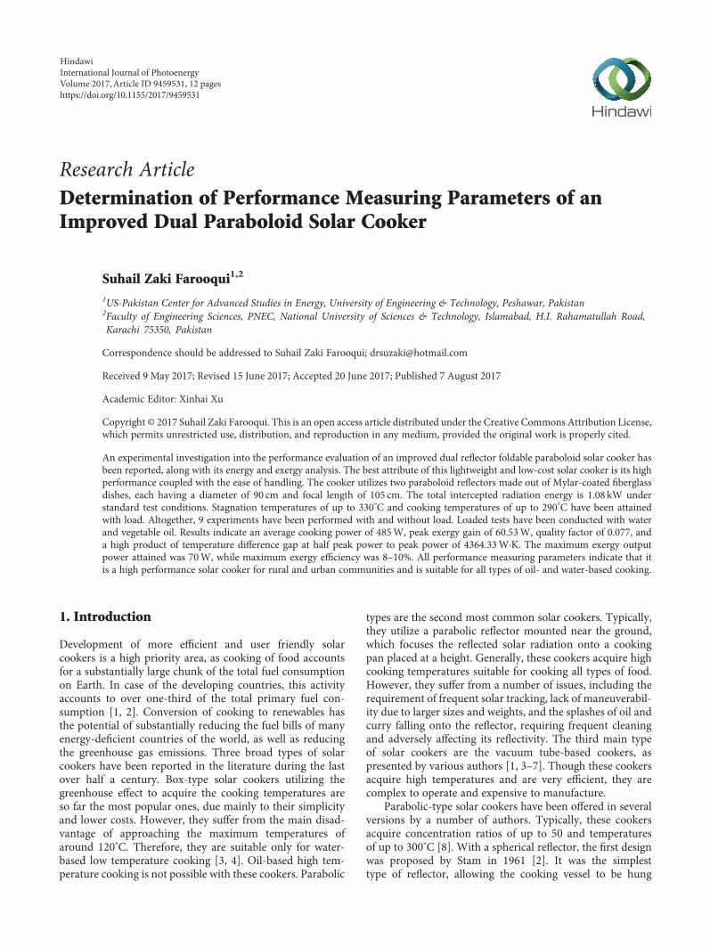
The Y-shaped frame shown in Figure 5 is made out offour rectangular pipe sections. Five wheels are connected atthe ends of the frame. The frame in Figure 4 is connected
to this frame through the 53 cm long welded rod and a hook,as shown. This frame supports the entire structure of thecooker and can be easily moved across over a flat surface.The total weight of the entire structure with fiberglass dishesis 12 kg.
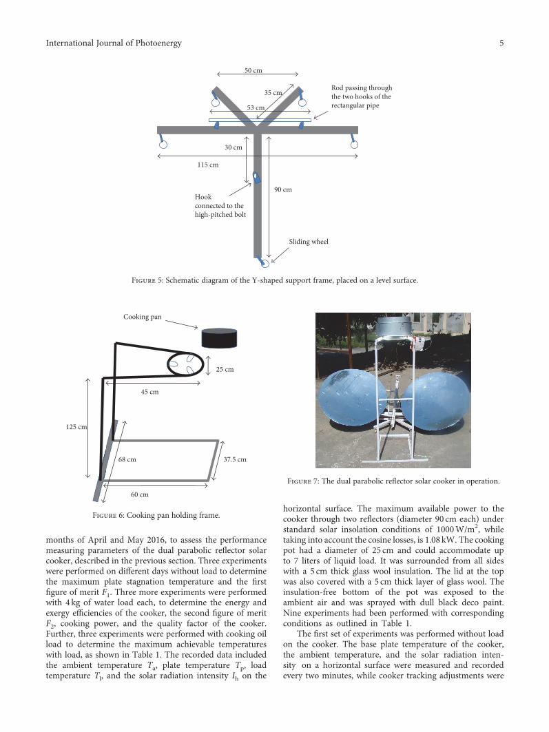
The last part of the cooker is the cooking pan holder. Theholder frame made out of angle iron, shown in Figure 6, is125 cm high, 60 cm long, and 37.5 cm wide and provides astructurally stable support for the cooking pan. The bottomof this frame is slipped between the two front wheels of theframe shown in Figure 5, such that any movement of thereflector frame does not cause any vibrations onto thecooking frame.
The complete dual parabolic reflector cooker in opera-tion is shown in Figure 7.
4. Performance Measuring Experiments
Several experiments had been performed on carefullyselected calm and clear days at 33.73° N latitude and 73.09° Elongitude test location (Islamabad, Pakistan), during the
75 cm40 cm
12.5 cm
17.5 cm
10 cm
10 cm
Reflectororientation
control screw
A B
17.5 cm
17.5 cm
a1
b1
a2
b2
Figure 3: Schematic diagram of the dual parabolic reflector support system with dimensions.
22 cm
78 cm
48 cm
20 cm
12 cm
30 cm
Altitude adjustment wheel
High-pitch screw
High-pitchcylindrical bolt
Rotational axis rod
12.5 cm
U-channel Endhook
Figure 4: Schematic diagram of the frame allowing the orientation control of the parabolic reflectors along the altitude.
4 International Journal of Photoenergy
months of April and May 2016, to assess the performancemeasuring parameters of the dual parabolic reflector solarcooker, described in the previous section. Three experimentswere performed on different days without load to determinethe maximum plate stagnation temperature and the firstfigure of merit F1. Three more experiments were performedwith 4 kg of water load each, to determine the energy andexergy efficiencies of the cooker, the second figure of meritF2, cooking power, and the quality factor of the cooker.Further, three experiments were performed with cooking oilload to determine the maximum achievable temperatureswith load, as shown in Table 1. The recorded data includedthe ambient temperature Ta, plate temperature Tp, loadtemperature Tl, and the solar radiation intensity Ih on the
horizontal surface. The maximum available power to thecooker through two reflectors (diameter 90 cm each) understandard solar insolation conditions of 1000W/m2, whiletaking into account the cosine losses, is 1.08 kW. The cookingpot had a diameter of 25 cm and could accommodate upto 7 liters of liquid load. It was surrounded from all sideswith a 5 cm thick glass wool insulation. The lid at the topwas also covered with a 5 cm thick layer of glass wool. Theinsulation-free bottom of the pot was exposed to theambient air and was sprayed with dull black deco paint.Nine experiments had been performed with correspondingconditions as outlined in Table 1.
The first set of experiments was performed without loadon the cooker. The base plate temperature of the cooker,the ambient temperature, and the solar radiation inten-sity on a horizontal surface were measured and recordedevery two minutes, while cooker tracking adjustments were
115 cm
90 cm
53 cm
50 cm
35 cm
30 cm
Sliding wheel
Hookconnected to thehigh-pitched bolt
Rod passing throughthe two hooks of the rectangular pipe
Figure 5: Schematic diagram of the Y-shaped support frame, placed on a level surface.
37.5 cm
60 cm
68 cm
125 cm
45 cm
25 cm
Cooking pan
Figure 6: Cooking pan holding frame.
Figure 7: The dual parabolic reflector solar cooker in operation.
5International Journal of Photoenergy

performed every five minutes. Digital thermometers UT33series, prepared by Uni-Trend Group Ltd., China, wereused for temperature measurement, while Apogee SP110pyranometer was used for the measurement of solar radia-tion intensity. The data plotted in Figures 8, 9, and 10indicates the stagnation temperatures attained in each case.
The blue curves in Figures 8, 9, and 10 show that themaximum temperatures attained during the three unloadedexperiments were 233°C, 258°C, and 331°C, respectively. Acomparison of these figures shows that the maximum platetemperature depends heavily on the existing intensity of thesolar radiation.
The second set of experiments was conducted with aload of 4 kg of water each time, on April 14, May 2, andMay 18, 2016, as per the recommended test load for solarcookers per unit aperture area per unit concentration ratio[19]. As shown in Figures 11, 12, and 13, 4 kg of waterload was brought to a boil in 28 minutes, 48 minutes, and34 minutes from starting temperatures of 42°C, 39°C, and36°C, respectively.
The last set of experiments was conducted with one liter(850 gm) of vegetable oil load each time, on April 22, 27,and 29, 2016. As shown in Figures 14, 15, and 16, the vegeta-ble oil attained maximum temperatures of 294°C, 262°C, and
285°C in 38 minutes, 64 minutes, and 56 minutes fromstarting temperatures of 101°C, 60°C, and 53°C, respectively.
Results of three sets of three experiments each have beenshown in the foregoing, with dual parabolic reflector soarcooker, during the months of April and May 2016. Theexperiments with no load on the cooker indicate that under
Table 1: Test conditions of nine experiments.
Exp. number Date of experimentExperiment start solar
time (H:M)Experiment endsolar time (H:M)
Load (gm)Max. temp.attained (°C)
1 April 13, 2016 09:40 10:30 Nil 233
2 April 13, 2016 12:18 12:46 Nil 258
3 April 22, 2016 11:26 12:18 Nil 331
4 April 14, 2016 13:46 14:14 4000 (water) 100
5 May 02, 2016 12:16 13:04 4000 (water) 100
6 May 18, 2016 12:24 12:58 4000 (water) 100
7 April 22, 2016 12:06 12:44 850 (oil) 294
8 April 27, 2016 10:56 12:00 850 (oil) 262
9 April 29, 2016 11:04 12:00 850 (oil) 285
0
50
100
150
200
250
9.6 9.7 9.8 9.9 10 10.1 10.2 10.3 10.4 10.5 10.6
Tem
pera
ture
(ºC)
, rad
iatio
nin
tens
ity (w
att/1
0)
Solar time (h)
Experiment number 1
Figure 8: Plot of temperature (blue) and solar radiation intensity(red) versus time for the first unloaded experiment. Radiationintensity is divided by 10 to fit the scale.
0
50
100
150
200
250
300
12.2 12.3 12.4 12.5 12.6 12.7 12.8Solar time (h)
Experiment number 2
Tem
pera
ture
(ºC)
, rad
iatio
nin
tens
ity (w
att/1
0)
Figure 9: Plot of temperature (blue) and solar radiation intensity(red) versus time for the second unloaded experiment. Radiationintensity is divided by 10 to fit the scale.
0
50
100
150
200
250
300
350
11.3 11.4 11.5 11.6 11.7 11.8 11.9 12 12.1 12.2 12.3 12.4Solar time (h)
Experiment number 3
Tem
pera
ture
(ºC)
, rad
iatio
nin
tens
ity (w
att/1
0)
Figure 10: Plot of temperature (blue) and solar radiation intensity(red) versus time for the third unloaded experiment. Radiationintensity is divided by 10 to fit the scale.
6 International Journal of Photoenergy

clear sky conditions, maximum plate temperatures as high as330°C may be attained in 30 to 40 minutes duration. Experi-ments with 4 kg of water load indicate that starting from the
ambient temperatures, it boils in 28 to 48 minutes, dependingupon the radiation intensity. The last set of experiments withvegetable oil load indicates the maximum attainable cookingtemperatures with load. Temperatures as high as 294°C havebeen attained this way, with the average attained temperature
0
20
40
60
80
100
120
13.7 13.8 13.9 14 14.1 14.2 14.3Solar time (h)
Experiment number 4Te
mpe
ratu
re (º
C), r
adia
tion
inte
nsity
(wat
t/10)
Figure 11: Plot of temperature (blue) and solar radiation intensity(red) versus time for the first experiment with 4 kg of water load.Radiation intensity is divided by 10 to fit the scale.
0
20
40
60
80
100
120
12.2 12.3 12.4 12.5 12.6 12.7 12.8 12.9 13 13.1 13.2Solar time (h)
Experiment number 5
Tem
pera
ture
(ºC)
, rad
iatio
nin
tens
ity (w
att/1
0)
Figure 12: Plot of temperature (blue) and solar radiation intensity(red) versus time for the second experiment with 4 kg of waterload. Radiation intensity is divided by 10 to fit the scale.
0
20
40
60
80
100
120
12.3 12.4 12.5 12.6 12.7 12.8 12.9 13Solar time (h)
Exepriment number 6
Tem
pera
ture
(ºC)
, rad
iatio
nin
tens
ity (w
att/1
0)
Figure 13: Plot of temperature (blue) and solar radiation intensity(red) versus time for the third experiment with 4 kg of water load.Radiation intensity is divided by 10 to fit the scale.
0
50
100
150
200
250
300
350
12 12.1 12.2 12.3 12.4 12.5 12.6 12.7 12.8Solar time (h)
Experiment number 7
Oil
tem
pera
ture
(ºC)
, rad
iatio
nin
tens
ity (w
att/1
0)
Figure 14: Plot of temperature (blue) and solar radiation intensity(red) versus time for the first experiment with 850 gm of vegetableoil load. Radiation intensity is divided by 10 to fit the scale.
0
50
100
150
200
250
300
10.8 11 11.2 11.4 11.6 11.8 12 12.2Solar time (h)
Experiment number 8
Oil
tem
pera
ture
(ºC)
, rad
iatio
nin
tens
ity (w
att/1
0)
Figure 15: Plot of temperature (blue) and solar radiation intensity(red) versus time for the second experiment with 850 gm ofvegetable oil load. Radiation intensity is divided by 10 to fit the scale.
0
50
100
150
200
250
300
11 11.2 11.4 11.6 11.8 12 12.2Solar time (h)
Experiment number 9
Oil
tem
pera
ture
(ºC)
, rad
iatio
nin
tens
ity (w
att/1
0)
Figure 16: Plot of temperature (blue) and solar radiation intensity(red) versus time for the third experiment with 850 gm ofvegetable oil load. Radiation intensity is divided by 10 to fit the scale.
7International Journal of Photoenergy

of about 280°C in 53 minutes. All these results indicate thatthe cooker presented in this paper is most suitable for ful-filling the oil-based high-temperature cooking needs of thepublic, while being user friendly, lightweight, and low cost.
The detailed performance measuring parameters of thecooker have been evaluated in the following sections.
5. Determination of the First and SecondFigures of Merit
In order to test the performance of solar cookers, two figuresof merit (FOM) are normally recommended. These aredefined as F1 and F2 [20, 21]. F1 (measured in m2K/W) isthe ratio of optical efficiency to the heat loss factor bythe bottom absorbing plate and is a measure of the differ-ential temperature gained by it at a particular level of solarinsolation. F2 gives an indication of heat transfer from theabsorbing base to the water inside the cooker.
Mathematically, they are defined as
F1 =Tps − Ta
Hs, 1
where Tps is the plate (tray) stagnation temperature, Hs isthe solar insolation on the horizontal surface, and Ta is theambient temperature.
F2 =F1 M ·C w
A · τ ln 1 − Twi − Taυ / F1 ·Haυ1 − Twf − Taυ / F1 ·Haυ
, 2
where (M ·C)w indicates the mass of the water in the potmultiplied to its heat capacity, A stands for the aperture areaof the cooker, τ is the time difference during which water washeated from an initial temperature Twi to the final tempera-ture Twf , Hav is the average solar radiation on a horizontalsurface, and Tav is the average ambient temperature duringthe experiment. F1 is evaluated in the absence of any loadon the solar cooker while F2 is evaluated in the presence offull load.
The cooking power of a cooker can be calculated as [21]
P = M ·C wΔTwΔt , 3
where ΔTw is the temperature difference of water acquiredin time Δt.
For the unloaded solar cooker described in thispaper, three experiments were conducted on April 13and April 22, 2016. The F1 calculation results are sum-marized in Table 2.
For the fully loaded (4 kg of water load) cooker, datawere collected on April 14, May 2, and May 18, 2016.For analysis, data are used for the water temperaturesbetween 60 and 90°C, for each experiment. The resultsare summarized in Table 3.
From the results in Tables 2 and 3, it is concluded that theaverage value of the first figure of merit F1 is 0.2578, whilethat of the second figure of merit F2 is 0.567. The averagecooking power of the solar cooker is 485W. For comparison,the typical value of F1 is 0.103, F2 is 0.309, and the cooking
power is 30W for typical box-type solar cookers [4], whileF1 is 0.395 and F2 is 0.654 for SK-14-type solar cooker with1.54m2 aperture area [12]. These parameters indicate thatthe dual parabolic cooker performance is comparable to thatof SK-14 solar cooker.
6. Determination of Exergy Efficiency andQuality Factor
Exergy efficiency is often measured and reported for a givensolar energy device as a measure of its potential for extractingheat from its surrounding environment [19, 22]. As per def-inition, the exergy approaches zero as the device approachesan equilibrium state with the environment. Exergy of thesolar radiation describes the exergy input to the solarenergy device and is determined by measuring the solarradiation flux (I°AΔt) during the experiment and usingthe relation [23, 24]:
EXi = I°AΔt 1 + TaTs
4 13 −
43
TaTs
, 4
where Ta and Ts, respectively, indicate the ambient air tem-perature during the experiment and the surface temperatureof the sun, I° represents the measured solar radiation inten-sity perpendicular to the collector at a given instant, Δt isthe time interval between two readings, and A indicates theaperture area of the solar collector under investigation. Theexergy output power of the device can be evaluated as [23]
Exo = Eout −M ·C ·Ta lnTwfTwi
, 5
where Twi is the initial and Twf is the final temperature ofwater (or any other material) placed inside the device. Mand C, respectively, represent the mass and the specific heatcapacity of the material.
The exergy efficiency may therefore be evaluated as
ψ = M ·C · Twf − Twi − Ta ln Twf /Twi /ΔtI° 1 + 1/3 Ta/Ts
4 − 4/3 Ta/Ts A6
Another important parameter is the exergy loss coeffi-cient, which is determined by measuring the differencebetween exergy input and output and the temperaturedifference δT between the water and the ambient air,defined as
EXloss= Exi − ExoA ·Δt · δT W/m2 K 7
Table 2: Calculation of the first figure of merit for the dual parabolicreflector solar cooker during experiment numbers 1, 2, and 3.
Exp. number Tas (°C) Tps (
°C) Hs (W/m2) F1 (m2K/W)
1 29.3 233 885 0.2302
2 30.5 258 900 0.2528
3 30.3 331 1035 0.2905
8 International Journal of Photoenergy

A plot of the exergy loss (Exi−Exo) versus δT can providethe overall heat loss coefficient of the cooker. Further, ithas been proposed that a plot between the exergy outputpower and δT, fitted with a second order polynomial,can be used to infer the peak exergy power of the deviceduring a particular experiment [25]. The plot may alsobe used to infer the temperature difference gap between
the temperatures corresponding to half exergy power points,on either side of the peak power point.
The exergy input power during the three experiments, asderived from (4), is shown in Figure 17.
The exergy output power during the three experiments,as extracted using 5 and fitted to a least-squares curve toshow the trend with time, is shown in Figure 18, while theexergy efficiency is plotted in Figure 19.
Table 3: Calculation of the second figure of merit and the cooking power for the dual parabolic reflector solar cooker for experimentnumbers 4, 5, and 6.
Exp. number Effective aperture area (m2) Twi (°C) Twf (
°C) Tav (°C) Hav (W/m2) Duration τ (seconds) (M ·C)w (J/K) F2 P (W)
4 1.08 60 92 36.6 852.4 960 16,800 0.638 560
5 1.08 60 91 41.8 814.6 1560 16,800 0.453 333.8
6 1.08 65 91 42.8 990.2 780 16,800 0.610 560
600
650
700
750
800
850
900
950
1000
1050
12 12.5 13 13.5 14 14.5
Exer
gy in
put p
ower
(W)
Solar time (h)
45
6
Figure 17: Exergy input power during the three experimentswith 4 kg of water load. Curves are labeled according to theexperiment number.
0
10
20
30
40
50
60
70
80
90
100
12 12.5 13 13.5 14 14.5
Exer
gy o
utpu
t pow
er (W
)
Solar time (h)
4
5
6
Figure 18: Exergy output power during the three experiments with4 kg of water load. Blue points correspond to experiment number 4,red to experiment number 5, and green to experiment number 6.
0
2
4
6
8
10
12
12 12.5 13 13.5 14 14.5
Exer
gy e�
cien
cy (%
)
Solar time (h)
4
5
6
Figure 19: Efficiency of the exergy output power during the threeexperiments with 4 kg water load. Blue points correspond toexperiment number 4, red to experiment number 5, and green toexperiment number 6.
y4 = −1.163x + 836.9y5 = −3.151x + 899.6y6 = −1.174x + 978.0
600
650
700
750
800
850
900
950
1000
1050
0 10 20 30 40 50 60 70
Exer
gy lo
ss (W
)
Temperature di�erence ΔT (K)
4
5
6
Figure 20: Least-squares fit to the exergy loss data for experimentnumbers 4, 5, and 6.
9International Journal of Photoenergy

The exergy loss data (EXi−Exo) is plotted versus thetemperature difference δT in Figure 20, corresponding toexperiment numbers 4, 5, and 6. The data are fitted withlinear curves. Heat loss coefficient (W/Km2) of the cookeris extracted by dividing the slopes of these curves by theaperture area of the cooker, while the specific heat losscoefficient (W/Kkgm2) is obtained by further division bythe amount of water. The quality factor of the solar cookermay be evaluated by dividing the peak exergy gained to theexergy lost at that instant [25].
Figure 21 shows the graphs between the output exergypower Exo and the temperature difference δT. The data arefitted to a second order polynomial, for all three experiments.The peak value of the exergy power and the temperaturedifference gaps corresponding to half peak power points havebeen extracted in each case.
The top three lines in the left of Figure 21 show theequations of the polynomial fits to the data for the threeexperiments. The bottom set of three lines shows the peakexergy power attained during each of the three experi-ments at a specific temperature difference. The third set
of three lines at the right top of Figure 21 provides thetemperature difference gaps at half peak exergy powerpoints. The temperature difference gaps are 68.96, 102.43,and 44.93K, respectively.
The average value of the peak exergy power for the threeexperiments is 60.53W, while the average temperature differ-ence gap at half peak power is 72.1K. The product of the peakpower with the temperature difference gap is therefore4364.33W·K. This value is by far the highest reported in lit-erature, for any solar cooker. Table 4 summarizes the variousexergy-based performance measuring parameters for theseexperiments and provides comparison of these parameterswith those of other types of solar cookers [1, 3, 4, 25].
From Table 4, it may be concluded that the specific heatloss coefficient for parabolic-type solar cooker is comparableto that of SK-14. The quality factor of this cooker is higherthan that of vacuum tube-type cooker and comparable tothose of Scheffler and SK-14 types. However, the peak exergygain, which determines the actual useful energy, is quite high,as compared to other types of solar cookers. Further, thetemperature difference gap at half peak power and its product
y4= −0.029x2 + 3.014x − 9.358y5 = −0.011x2 + 1.332x + 1.659y6 = −0.065x2 + 5.060x − 27.81
0
10
20
30
40
50
60
70
80
90
0 10 20 30 40 50 60 70
Exer
gy o
utpu
t pow
er (W
)
Temperature di�erence ΔT (K)
4
5
6
Pmax4 = 68.95 W at ΔT = 51.96 KPmax5 = 41.98 W at ΔT = 60.55 KPmax6 = 70.665 W at ΔT = 38.92 K
Phalfmax4 = 34.475 W at ΔT = 17.48 K & ΔT = 86.45 KPhalfmax5 = 20.99 W at ΔT = 16.86 K & ΔT = 104.23 KPhalfmax6 = 37.865 W at ΔT = 16.46 K & ΔT = 61.39 K
Figure 21: Exergy output power versus the temperature difference. Data are fitted with second order polynomials. Curves are labeledaccording to the experiment number.
Table 4: Various exergy-based performance measuring parameters for three types of solar cookers.
Cooker parameter Dual parabolic SK-14 Sheffler type Box type Vacuum tube type
Slope of exergy loss curve (W/K) 1.828 5.407 19.485 0.577 2.63
Aperture area (m2) 0.049 1.47 8.21 0.4326 0.107
Heat loss coefficient (W/Km2) 37.31 40.35 54.125 1.334 24.58
Specific heat loss coefficient (W/K kgm2) 9.326 8.07 2.706 0.417 4.916
Peak exergy gain (W) 60.53 18.21 55.75 48.39 55.6
Exergy lost at peak exergy gain (W) 805.87 171.79 560.606 377.90 1323.8
Quality factor 0.077 0.106 0.099 0.1281 0.042
Temperature difference at peak power (K) 50.48 30.33 29.165 31.64 55.2
Temperature difference gap at half power (K) 72.1 40.374 39.62 41.76 38.75
Product of temperature difference gap at half power topeak power (W·K) 4364.33 735.3 2208.815 2020.77 2154.5
10 International Journal of Photoenergy

with the peak exergy gain are substantially higher comparedto any other solar cooker reported so far. The average energyefficiency during the three experiments was 46.3%, 39.9%,and 49.38%, respectively. Due to design improvements inthe present cooker, the maximum energy (49.38%) andexergy (8–10% from Figure 19) efficiencies have substantiallyimproved compared to the results reported for a singleparabolic trough cooker, where maximum energy efficiencywas 15.7% and maximum exergy efficiency was 1.25% [23].Similarly, these parameters are substantial improvementsover SK-14 and Sheffler-type parabolic solar cookers [25].
7. Conclusions
This paper presents the results of an experimental investiga-tion of an improved dual parabolic reflector solar cookeralong with its construction details. The cooker has beenexplicitly designed from the point of view of a common userin terms of its usefulness and ease of transportation andhandling, while addressing several other issues prevalent withsuch cookers. The cooker has been extensively tested underdifferent load conditions and without load. All test resultssupport it as a substantial improvement over other solarcookers in terms of its capacity of cooking all types of foodas well as faster cooking with a view to its portability andlightweightiness. The various standard performance measur-ing parameters have been evaluated at a test load of 4 kg ofwater. The average cooking power of the cooker has beenfound to be 485W, while the maximum attainable tempera-tures with load approached 290°C. Many cooking experi-ments like frying of eggs and French fries and making ofbread have been conducted several times with great ease.The cooker has high exergy gain of up to 70W, with 8–10%maximum efficiency, while the thermal efficiency of thecooker is up to 49.4%. The product of peak exergy powerto the temperature difference gap, which is an importantparameter for comparing the performance of solar cookers,has been found to be 4364.33W·K, which is by far the highestreported in the literature, for any solar cooker. The cooker islow cost (around US$ 100) and easy to manufacture. It isquite ready for large scale dissemination.
Conflicts of Interest
The author declares that he has no conflicts of interest.
Acknowledgments
This work has been conducted at the Pakistan Council ofRenewable Energy Technologies, Islamabad. The author isgrateful to the council for extending its funds, facilities, andmanpower for carrying out this study.
References
[1] S. Z. Farooqui, “A review of vacuum tube based solar cookerswith the experimental determination of energy and exergy effi-ciencies of a single vacuum tube based prototype,” Renewableand Sustainable Energy Reviews, vol. 31, pp. 439–445, 2014.
[2] R. M. Muthusivagami, R. Velraj, and R. Sethumadhavan,“Solar cookers with and without thermal storage—a review,”Renewable and Sustainable Energy Reviews, vol. 14, no. 2,pp. 691–701, 2010.
[3] S. Z. Farooqui, “Impact of load variation on the energy andexergy efficiencies of a single vacuum tube based solar cooker,”Renewable Energy, vol. 77, pp. 152–158, 2015.
[4] S. Z. Farooqui, “Angular optimization of dual booster mirrorsolar cookers – tracking free experiments with three differentaspect ratios,” Solar Energy, vol. 114, pp. 337–348, 2015.
[5] A. Balzar, P. Stumpf, S. Eckhoff, H. Ackermann, and M.Grupp, “A solar cooker using vacuum-tube collectors withintegrated heat pipes,” Solar Energy, vol. 58, no. 1–3,pp. 63–68, 1996.
[6] S. Z. Farooqui, “A vacuum tube based improved solarcooker,” Sustainable Energy Technologies and Assessments,vol. 3, pp. 33–39, 2013.
[7] R. Kumar, R. S. Adhikari, H. P. Garg, and A. Kumar,“Thermal performance of a pressure cooker based on evac-uated tube solar collector,” Applied Thermal Engineering,vol. 21, pp. 1699–1706, 2001.
[8] K. Ashok, “A review of solar cooker designs, TIDE (TERIinformation digest on energy),” vol. 8, no. 1, pp. 1–37, 1998.
[9] S. C. Mullick, T. C. Kandpal, and S. Kumar, “Thermal testprocedure for a paraboloid concentrator solar cooker,” SolarEnergy, vol. 46, no. 3, pp. 139–144, 1991.
[10] M. M. Rathore and R. M. Warkhedkar, “A review of solarcookers, international journal of modern trends in engineeringand research, special issue of ICRTET’2015,” vol. 2, no. 7,pp. 1997–2004, 2015.
[11] A. S. Ahmed, N. S. P. Rao, P. L. S. Murthy, and B. P. Terani,“Detail study of parabolic solar cooker SK-14,” InternationalResearch Journal of Engineering and Technology, vol. 2, no. 4,pp. 24–27, 2015.
[12] A. Chandak, S. K. Somani, and P. M. Suryaji, “Comparativeanalysis of SK-14 and PRINCE-15 solar concentrators,” inProceedings of the World Congress on Engineering 2011 VolIII WCE 2011, London, UK, July 6–8, 2011.
[13] W. Scheffler, “Introduction to the revolutionary Design ofScheffler Reflectors,” Germany, November 2016, http://www.solare-bruecke.org.
[14] W. Scheffler, “The Scheffler reflector, Solare Brucke,”November 2016, http://www.solare-bruecke.org/index.php/en/die-scheffler-reflektoren.
[15] C. Reichl, F. Hengstberger, and C. Zauner, “Heat transfermechanisms in a compound parabolic concentrator: compari-son of computational fluid dynamics simulations to particleimage velocimetry and local temperature measurements,”Solar Energy, vol. 97, pp. 436–446, 2013.
[16] Y. Yoshiki Nishi and T. Sema, “Estimation of exergy efficiencyof compound parabolic concentrator under time-varyingcloud cover condition,” Solar Energy, vol. 98, pp. 341–348, 2013.
[17] W. B. Stine and M. Geyer, ““Power from the sun”, J.T.Lyle Center for Regenerative Studies,” John Wiley and Sons,Incorporated, 2001.
[18] Mylar, “All you need to know about,” October 2016, https://www.mjguide.com/tutorials/Lighting/1568.htm.
[19] P. A. Funk, “Evaluating the international standard procedurefor testing solar cookers and reporting performance,” SolarEnergy, vol. 68, pp. 1–7, 2000.
11International Journal of Photoenergy

[20] S. C. Mullick and S. K. Kandpal, “Testing of box type solarcookers: second figure of merit - F2 and its variation with loadand number of pots,” Solar Energy, pp. 409–413, 1996.
[21] G. N. Tiwari, “Solar energy: fundamentals, design, modelingand applications,” Alpha Science International, 2002.
[22] R. Petela, “Exergy of undiluted thermal radiation,” SolarEnergy, vol. 74, pp. 469–488, 2003.
[23] H. H. Ozturk, “Experimental determination of energy andexergy efficiency of the solar parabolic-cooker,” Solar Energy,vol. 77, pp. 67–71, 2004.
[24] R. Petela, Engineering Thermodynamics of Thermal Radiationfor Solar Power Utilization, McGraw-Hill, New York, 2010.
[25] N. Kumar, G. Vishwanath, and A. Gupta, “An exergy basedunified test protocol for solar cookers of different geometries,”Renewable Energy, vol. 44, pp. 457–462, 2012.
12 International Journal of Photoenergy

Submit your manuscripts athttps://www.hindawi.com
Hindawi Publishing Corporationhttp://www.hindawi.com Volume 2014
Inorganic ChemistryInternational Journal of
Hindawi Publishing Corporation http://www.hindawi.com Volume 201
International Journal ofInternational Journal ofPhotoenergy
Hindawi Publishing Corporationhttp://www.hindawi.com Volume 2014
Carbohydrate Chemistry
International Journal ofInternational Journal of
Hindawi Publishing Corporationhttp://www.hindawi.com Volume 2014
Journal of
Chemistry
Hindawi Publishing Corporationhttp://www.hindawi.com Volume 2014
Advances in
Physical Chemistry
Hindawi Publishing Corporationhttp://www.hindawi.com
Analytical Methods in Chemistry
Journal of
Volume 2014
Bioinorganic Chemistry and ApplicationsHindawi Publishing Corporationhttp://www.hindawi.com Volume 2014
SpectroscopyInternational Journal of
Hindawi Publishing Corporationhttp://www.hindawi.com Volume 2014
The Scientific World JournalHindawi Publishing Corporation http://www.hindawi.com Volume 2014
Medicinal ChemistryInternational Journal of
Hindawi Publishing Corporationhttp://www.hindawi.com Volume 2014
Chromatography Research International
Hindawi Publishing Corporationhttp://www.hindawi.com Volume 2014
Applied ChemistryJournal of
Hindawi Publishing Corporationhttp://www.hindawi.com Volume 2014
Hindawi Publishing Corporationhttp://www.hindawi.com Volume 2014
Theoretical ChemistryJournal of
Hindawi Publishing Corporationhttp://www.hindawi.com Volume 2014
Journal of
Spectroscopy
Analytical ChemistryInternational Journal of
Hindawi Publishing Corporationhttp://www.hindawi.com Volume 2014
Journal of
Hindawi Publishing Corporationhttp://www.hindawi.com Volume 2014
Quantum Chemistry
Hindawi Publishing Corporationhttp://www.hindawi.com Volume 2014
Organic Chemistry International
ElectrochemistryInternational Journal of
Hindawi Publishing Corporation http://www.hindawi.com Volume 2014
Hindawi Publishing Corporationhttp://www.hindawi.com Volume 2014
CatalystsJournal of