determination of streamlines using a photoviscous fluid
TRANSCRIPT

Retrospective Theses and Dissertations Iowa State University Capstones, Theses andDissertations
1956
Determination of streamlines using a photoviscousfluidDonald Fredrick YoungIowa State College
Follow this and additional works at: https://lib.dr.iastate.edu/rtd
Part of the Applied Mechanics Commons
This Dissertation is brought to you for free and open access by the Iowa State University Capstones, Theses and Dissertations at Iowa State UniversityDigital Repository. It has been accepted for inclusion in Retrospective Theses and Dissertations by an authorized administrator of Iowa State UniversityDigital Repository. For more information, please contact [email protected].
Recommended CitationYoung, Donald Fredrick, "Determination of streamlines using a photoviscous fluid " (1956). Retrospective Theses and Dissertations.12907.https://lib.dr.iastate.edu/rtd/12907

NOTE TO USERS
This reproduction is the best copy available.
UMI


DETEEMIHATION OF STEEAMLINES USING
A FHOTOVISCOUS FLUID
by
Donald Fredrick Young
A Dissertafclon Submitted to the
Oraduate Faculty in Partial Fulfillment of
The Eequlrements for the Degree of
DOCTOE OF PHILOSOPHY
Major Subject: Theoretical and Applied Mechanics
Approved:
Work
rtment
Be Q^oi ta'raiuate College
towa State College
1956
Signature was redacted for privacy.
Signature was redacted for privacy.
Signature was redacted for privacy.

UMI Number: DP11969
INFORMATION TO USERS
The quality of this reproduction is dependent upon the quality of the copy
submitted. Broken or indistinct print, colored or poor quality illustrations and
photographs, print bleed-through, substandard margins, and improper
alignment can adversely affect reproduction.
In the unlikely event that the author did not send a complete manuscript
and there are missing pages, these will be noted. Also, if unauthorized
copyright material had to be removed, a note will indicate the deletion.
UMI UMI Microform DP11969
Copyright 2005 by ProQuest Information and Learning Company.
All rights reserved. This microform edition is protected against
unauthorized copying under Title 17, United States Code.
ProQuest Information and Learning Company 300 North Zeeb Road
P.O. Box 1346 Ann Arbor, Ml 48106-1346

ii
TABLE OF CONTENTS
Page
INTRODUCTION 1
REVIEW OF LITERATURE 3
BACKGROUND THEORY 7
Optical Theory as Applied to Stress Analysis 7
Fundamental Equations for Viscous Fluids 11
METHOD OF APPROACH 16
EXPERIMENTAL INVESTIGATION 26
Determination of Fluid Properties 26
Description of Optical Equipment 29
Description of Flow Channel 30
Test Procedure 35
RESULTS 36
General Experimental 36
Analysis 79
Proposed Method for Prediction of Flow Patterns 91 -92
SUMMARY AND CONCLUSIONS 95
RECOMMENDATIONS FOR FURTHER XNVESTlGATiONS 97
LITERATURE CITED 99
ACKNOWLEDGEMENTS 101
77<2

iii
LIST OF SYMBOLS
radius of cylinder
characteristic length of half-body
velocity of light
thickness of double-refracting specimen
acceleration of gravity
photoelastic constant
pressure
normal stresses in x, y, % directions, respectively
shearing stress acting on yz-plane in the y-direction
shearing stress acting on xz-plane in the z-direction
shearing stress acting on xy-plane in the x-direction
maximum shearing stress
principal stresses
time
period
velocity components in x, y, z directions* respectively
maximum free stream velocity at infinity
body forces in x, y, z directions, respectively
angle between xy-plane and principal stress direction
angle between optic axis and analyzer axis
initial angular displacement
wavelength

iv
it. 3 absolute viscosity
p « density of fluid
0 3! potential function
3 stream function
w S angular frequency
Subscripts
c s circular cylinder
hh 3 kail-body
00 S infinity
o 3 ideal fluid

i
INTRODUCTION
One of the most difficult problems which arise in the field of fluid
mechanics is the prediction of the flow pattern of a real fluid around a
submerged body. There are no known general solutions for the non
linear differential equations which describe the flow of a real fluid, and
exact solutions have been obtained for only a few special cases. Since
the problem of describing the flow around objects is an important one
several experimental techniques have been developed.
One of the most common methods of obtaining quantitative results is
the insertion of a probe, such as a pitot tube, into the fluid and measur
ing the pressure at various points in the system. This technique has
the disadvantage of disrupting the flow pattern in the immediate vicinity
of the probe and the results are sometimes questionable with regard to
what is actually being measured. However, this technique has been used
with success for many years.
Another method which has been used extensively is that of injecting
dye or other foreign particles into the fluid and visually observing the
flow pattern. This technique has the advantage of not disrupting the flow
but is not completely satisfactory since quantitative results are not easily
obtained.
A visual technique which would give quantitative results would there
fore be of value and this fact has brought into prominence the use of
•'photoviscous*' fluids in the study of flow problems.

2
It is well known that certain transparent solids, such as Bakelite,
are double refracting when stressed. The double refraction can be re
lated to the stresses in the solid and methods have been developed for
determining the stresses froro visual observations.
Maxwell ( 1 3 ) first observed the phenomenon of double refraction in
liquids in 1866. Fluids which exhibit this property have been called
"photoviscous" fluids. Experiments have indicated that the double
refraction in the liquid can be related to the stresses which arise when
the liquid is in motion. Since the stresses in the fluid can be related to
the velocity gradients the possibility of using photoviscous fluids for
the prediction of flow patterns has been recognized for many years.
Even though the potential of this technique has been realized little
work has been done in the direct application to the field of fluid mech
anics. Most of the previous investigators have been primarily interested
in the problem from a physical-chemistry viewpoint. Much of the research
in this area has been concerned with theories of the cause of double re
fraction in liquids. As yet no completely satisfactory theory has been
developed.
The object of this investigation was to determine the feasibility of using
a photoviscous fluid for the quantitative prediction of general two-
dimensional flow patterns around submerged bodies and to determine the
required techniques. No attempt has been made to explain the underlying
reasons for the double refraction. The emphasis has been placed on the
solution to fluid mechanics problems from a phenomenological viewpoint.

3
REVIEW OF LITERATURE
As mentioned in the Introduction, a great deal of research has been
undertaken which is directly or indirectly related to the structure of
photoviscous fluids. Published papers in this area have not been included
in the review of literature and only investigations directly concerned with
fluid mechanics problems have been studied. However, several reviews
have been made by other authors which cover all phases of the problem.
One of the most complete reviews has been noted.
Although a photoviscous fluid was first described by Maxwell (13) in
a publication in 1873 it was not until 1924 that any published work appeared
in which a photoviscous fluid was utilized in a flow problem. In this
paper Humphrey (8) described an experiment in which he used a vanadium
pentoxide solution to study qualitatively some simple flow problems. In
1935 Alcock and Sadron (1) published a report on the quantitative study of
velocity gradients for two-dimensional parallel flow, flow In a divergent
channel, and flow in a concentric-cylinder device. They used a liquid,
sesame oil, for their Investigation and estimated that the velocity gradients
could be measured within 0, 1 mm of the solid boundary. Due to this fact
they noted the possibility of using photoviscous fluids for boundary layer
studies. In 1939 Hauser and Dewey (6) described. In a brief note, experi
ments in progress using aqueous suspensions of bentonlte clay. In 1942
Dewey gave the results of this study In his thesis. Still pictures and motion

4
pictures were taken of the isoclinic and fringe patterns around various
shapes and the quantitative prediction of flow patterns was attempted. Also
in 1942 Weller, Middlehurst, and Steiner (2i) published a report in which
the photoviscous properties of 59 different liquids were evaluated. The
most satisfactory fluid was a solution of ethyl cellulose in ethylene glycol
methyl ether acetate and this fluid was used in the study of flow in a rec
tangular channel, around a cylinder, and around a strut section. The
authors noted that although the flow was two-dimensional a velocity gradi
ent in the direction of the incident light ray existed and this would affect
the stress pattern.
One of the most practical applications was made by Leaf (9) and re
ported in 1945. In connection with the design of locomotive fireboxes Leaf
used a bentonite clay suspension and obtained stress patterns which were
useful in improving the design of the firebox. No quantitative results were
obtained. In 1945 Binnie (2) and in 1947 Binnie and Fowler (3) published
papers concerning the onset of turbulence in a long circular glass tube.
They used a weak solution of benzopurpurin in water and studied the effect
of the entrance conditions and the distance downstream from the entrance
on the breakdown of laminar flow. Under conditions of steady laminar flow
the polarized light passing through the double-refracting liquid was steady
but as the velocity Increased the emergent light beam became unsteady and
the disturbance was believed to indicate the development of turbulence.
The degree of unsteadiness of the light beam was measured by a photocell
which was connected through an amplifier to a cathode-ray tube. In i947
Ullyott (19) reported on an Investigation In which he used a vanadium

5
pentoxide solution to study flow patterns. Pictures of the stress patterns
around an airfoil, cylinder and a flat plate were presented but no analysis
was 3X1 ade.
Rosenberg (18) in 195E published a report in which he discussed the
use of both colloidal suspensions and liquids for qualitative and quantita
tive flow studies. An analytical study was made of the most likely orienta
tion of long slender rods suspended in a fluid. He also discussed the
possibility of erroneous results when calibration data taken in a parallel
flow system were used for the prediction of general two-dimensional
flow patterns. No experimental results were contained in the report.
In 1953 Peebles, Garber, and Jury (14) published a paper in which a
new photoviscous fluid was described. This fluid was an aqueous sus
pension of an organic dye, called milling yellow, which was easily pre
pared, stable and sensitive. Stress patterns were obtained for flow
through and around various configurations. In 1954 a report by Peebles,
Prados, and Honeycutt (15) was published in which the optical and physi
cal properties of the milling yellow solution were described. A thorough
literature survey on flow double refraction was included. This survey
covered all phases of research connected with photoviscous fluids. In
1955 Prados and Peebles (17) published a second report on the optical
and physical properties of the milling yellow solution. None of the re
ports concerning th© milling yellow studies contained any quantitative
flow analysis except for flow in a concentric-cylinder apparatus. How
ever, the authors stated that further flow studies were contemplated.

6
lo 1955 Wayland (20) reported on the laminar and turbiilent flow In
th® annular space between a fixed outer and a rotating inner cylinder,
A colloidal suspension of bentonite clay in water and a liquid, ethyl
cinnamate* were used in the investigation. For the colloidal suspension
the shear stress in turbulent flow could be evaluated only when, for a
given amount of birefringence, the angle between the streamline and
the optic axis (esctinetion angle) was the same for both turbulent and
laminar flow. For a liquid the extinction angle remained at 45 degrees
under all conditions. Therefore the mean shear stress in two-
dimensional turbulent flow could be evalmted from the liquid.
Within the last year papers by Lodge (10, 11, 12) and Philippoff
(I4) were pt^lished which appear to have some bearing on the results
given in this thesis. A further reference to these papers is made in
the section on Results.

7
BACKGROUND THEOEY
The application of photoviscous fluids to fluid mechanics problems
requires some familiarity with not only the fundamental concepts of fluid
mechanics but also some optical theory as it is related to stress analysis.
In both areas the theory has been well developed. However, the optical
theory which holds for solids in the elastic range may not be valid for
double >refracting fluids and the classical equations for Newtonian fluids
may not be valid for photoviscous fluids which are generally non-
Newtonian. Therefore the limitations and assumptions which are made
for the conventional work have been considered in detail. The following
two sections give some of the fundamental concepts of the optical theory
and the flow theory. The main emphasis has been placed on the assump
tions made in arriving at the various relationships.
Optical Theory as Applied to Stress Analysis
A material is said to be double refracting if an incident plane polar
ized light ray is broken up into two component raye as it passes through
the material. The resolution of the light ray is illustrated in Fig. i
where OC is the incident ray and OA and OB are the component rays.

8
Axis of incident polarized light
C
B
A
Analyzer axis 0
Fig. i. Resolution of plane polarized light ray
If a polarizing element caUed the analyzer is placed with its axis
perpendicular to the original axis of polarization the light ray passing
through the analyzer will have a magnitude represented by the difference
of the two vectors OA' and OB'. The displacement of the component OA
In the OA direction at any time t can be written as
The magnitude of the resultant light ray emerging from the analyzer is
OA « OG sin ^ sin (wt + c) , (i)
and the displacement of OB in the OB direction as
OB s! OC cos p sin ( ut + f) . (2)
B, s Of! ft
— s i n 2 ̂ s i n ( w t ^ - f - e ) - s i n ( u t ^ + « )

The tim&a and are not necessarily the same since the component rays
travel with different velocities through the material. In solids the velocity
is dependent on the magnitude ol the principal stresses.
Equation (3a) Indicates that there will be no light transmitted under
two conditions.
(1) When sin 2p s 0. This condition Is satisfied If the plane of polari
zation coincides with either of the planes contaning the OA or OB vectors.
A dark spot will appear In the material wherever this condition Is satis
fied and the locus of these points is called an "Isocllnlc". For solids It
has been well established that the Incident light ray Is resolved Into
components in the principal stress directions and therefore the directions
of the principal stresses can be determined from the Isocllnlcs. This
fact has not been confirmed for all photovlscous fluids.
(2) When sin (wt^ + c) = sin + e) . (4)
This condition Is satisfied if
where n is an integer. The relationship between t^ and can be written
y t j + € = u t ^ + e + 2 n i r (5)
as
t J = t2 + At (6)
and Equation (5) reduces to
w At = 2nir (7)
as the necessary condition for extinction. Since

10
Equation (7) can also be written as
c At = An . (9)
The term cAt is the relative retardation between the component rays as
they pass through the body. On® of the fundamental theorems in solid
photoelasticity is the relationship between the retardation and the princi
pal stresses
C At =Kd /"Sj - $2J . (iO)
Substitution of Equation (10) into Equation (9) gives
Kd - S^J . ill)
Therefore when the difference in the principal stresses is such that Equa
tion (11) is satisfied extinction of the emergent light ray will be accom
plished. If th® incident light ray is monochromatic, i.e. the wave length
is a constant, for each integral value of n a series of black spots will be
formed in the specimen wherever Equation (11) is satisfied. The loci of
these points are called "fringes". If the incident light ray is white light
the stressed areas in the specimen, as viewed through the analyzer , will
appear in colors as certain components of the white light are extinguished.
Upon proper calibration the colors can be related to the difference of the
principal stresses. Each line of a single color is called an "isochroma-
tic".
It is apparent that a double-refracting material when subjected to a
stress will produce both isoclinics and isochromatics. However, the
isoclitiics can be removed by using circularly polarized light.

11
Altliougli the fundamental x-elationship given by Equation (i l) has been
experimentally verified for solids it has not been confirmed for all photo-
viscous 0uids.
Fundamental Equations for Viscous Fluids
Three faces of an infinitesimal volume of a viscous fluid are shown in
Fig. 2 and the stresses acting on these boundaries are illustrated. The
forces acting on the boundaries of the differential volume of fluid can be
evalimted in terms of the stresses, and the equations of motion for the
element can be derived from Newton's Second Law. The equations of
motion are usually written as
r 9u ^ 8u ^ 8u 1 V . ,,, , p j ^ u ^ + v ^ + w ^ J = x + - ^ + + - 5 ^ C 1 2 a )
r , 9^^ . ^ , 8W7 , , ^®yz . ^ ly + ^ {12c)
When the force of gravity is the only external force acting on the system,
the body forces X, Y, and Z are simply the components of the weight
per unit volume. The only restriction on Equations (12) is that the fluid
is homogeneous and the flow is steady. H wever, for all of the following
work the fluid is also assumed to be incompressible, i.e. the density is
a constant.

u
y
xz
zy
yz
yx
z
Figo 2 - General stress systwn at a point in a TI BCOUS fluid

13
One of the basic assumptions which is made in classical fluid dy
namics is that the stresses are proportional to the rate of change of
strain. With this assumption the stress components can be written as
(13a)
(13b)
(13c)
(13d)
(13e)
(13f)
Fluids which obey the preceding relations between stress and rate of
strain are called ''Newtonian" fluids. A combination of Equations (13)
with Equations (12) gives the famous Havier«Stokes equations for
incompressible flow.
P
P
P
In order to describe the motion of a fluid one other equation is required
and it is simply derived from the principle of conservation of mass. For
9u s - p + Zp.
Sy = - P + 2}A 8v Wf
SGJ A - P + 2{A ^
xy
yz
xz
j8u 8v Wc
fav . dw iy
fSw , 8u"
r 9u , 9u . du 1 ^ dp r 5H + ^ Sy ^ " 5FJ=
r 0V ^ Bv . „ 9p ^ u ^ + v ^ - f - w ^ b +
r 9 w , & w , 0 ^ _ t / p ^ U ^ + V | ^ + W ^ J a Z - - ^ + [ 1 .
dhi ^ 9% ^ dhi
_dx^ ay» 9z*
'Bhr ^ dhr -
dx^ 8y* dz^
^ 9^ , 9^
8x2 dyi
(14a)
(14b)
(14c)

1.4
an tecoinpressible fluid this principle leads to the so-called continuity-
equation X 4. AFT n5\
Equation® ^14) and Equation (15J completely describe the problem mathe
matically since there are four equations and four unknowns, u, v, w and
p. Unfortunately, however, the Navier-Stokes equations are non-linear
and, as mentioned in the introduction, there are no known general solu
tions, Certain assumptions can be made which will linearize the equa
tions and this has been the technique used to obtain approximate solutions
for many problems.
The assumption which gives the simplest solution is to assume that
the fluid is "ideal", i.e. the viscosity is zero. Under this condition the
velocities can be expressed as the gradient of a potential function 0, so
that
80 30 30
where the potential function satisfies the Laplace equation
02 g g2;0 a 2(« £_£ «o . (16)
8y^ 9a2
Solutions of this form do not satisfy the condition of no slip at the
boundary and are therefore not physically realistic. H wever, for fluids
with small viscosities the predicted flow patterns away from the boun
daries are in fair agreement with experimental results.
For slow motions of viscous fluids the inertia terms in the Navier-
Stokes eqtiations can be neglected and under this assumption the equa
tions take the form

15
(17a)
(17b)
8p _ . 8^ , dhv , 9^ ^ a Z + jjl + + ^ 8x2 8y2 Q^z
(17c)
Although Equations (17) are linear they are still difficult to solve but a
number of solutions have been obtained.
In many two-dimensional flow problems it is convenient to introduce
a stream function which is defined so that
lines in the flow field.
Of course any solution based on the Navier-Stokes equations is valid
only if the fluid involved is Newtonian. Since most photoviscous fluids
are non-Newtonian, the use of the Navier-Stokes equations in conjunc
tion with flow problems where photoviscous fluids are utilized will, at
best, give only approximate results.
It can readily be shown that lines of constant

16
METHOD OF APPROACH
As indicated in the Review of Juiterature Dewey (4) has been the only
Investigator who quantitatively predicted the flow pattern around a sub
merged body. Dewey calibrated the Euid in a concentric-cylinder
apparatus and used the calibration curves to predict the flow patterns
around various geometrical shapes. This technique is questionable for
reasons given in the following discussion.
The concentric-cylinder device is composed of two cylinders, one
rotating relative to the other. The relative velocity between the walls
of the cylinder creates a velocity gradient which can be calculated and
related to the shearing stress in the fluid if Newtonian relationships are
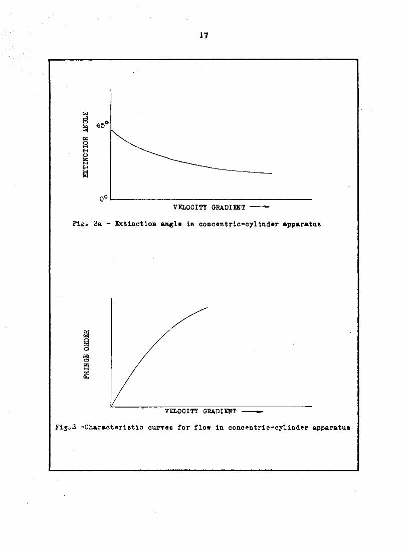
assimied. The characteristic curves which are obtained with this set-up
are indicated in Figs. 3a and 3b.
The extinction angle has been defined as the angle between the stream
line and the optic axis in the fluid, where the optic axis corresponds to
one of the axes of polarization in the fluid. If the plots shown in Figs.
3a and 3b are assumed to be valid for the general case of two-dimensional
flow around a submerged body the prediction of the streamline Is a rela
tively simple matter when the optic axis angle and the fringe order are
known. From the fringe order the velocity gradient can be obtained from
Fig. 3b. The extinction angle can then be evaluated from Fig. 3a. Since
the streamline angle is the difference between the optic axis angle and
the extinction angle it can be determined. This was the method used by
Dewey.
It
En s
VKLOCin GRADIIST
Flgo 3a - IxtinctlOB angle in concentric-cylinder apparatus
VELOCITY GEADIENT
FigpS -Characterifttic curres for flow in concentric-cylinder apparatus

18
However, two questions arise as to the validity of this technique.
1. la one of the important variables the angle between the optic axis
and the streamline or the angle between the optic axis and the plane of
maximum shear? This question cannot be answered from concentric-
cylinder data because the streamline and the plane of maximum shear
coincide. If the latter definition is used to define the extinction angle a
more Involved analysis would be required since the direction of the maxi
mum shear would be the quantity obtained in the unknown flow field and
this in turn would have to be related to the streamline,
2, Are the calibration curves obtained in the concentric-cylinder
apparatus valid for the getieral two-dimensional flow field? The stream
lines in the concentric-cylinder are all parallel and there is no velocity
gradient in the direction of the streamline, whereas for the more general
case the streamlines are not necessarily parallel and there is a velocity
gradient along the streamline. Again this question cannot be resolved
from concentric-cylinder data.
Answers to the preceding questions are necessary before a reliable
prediction technique can be determined. Since the concentric-cylinder
apparatus does not give the required information, a new experimental
set-up was needed. In order to obtain the required type of data It was
necessary to study the flow in a general two-dimensional field for which
the 0OW parameters such as streamline angle, rate of shear, etc. could
be evaluated analytically. A correlation between the flow parameters and
the isoclinic and fringe patterns could then be attempted for the general
case.

19
The fluid used for all of the studies contained in this thesis was a solu
tion of milling yellow and distilled water. As reported by Peebles,
Garber, and Jury (14) the milling yellow solution was easily prepared,
stable, and sensitive. It also has an apparent viscosity which is com
parable to that of water whereas many of the photovlscous fluids are
extremely viscous. The milling yellow solution is non-Newtonian as
indicated in Fig. 5 of the following section.
One of the i»ajor problems was the selection of a system In which the
flow parameters could be calculated mathematically. There are no exact
solutions for the flow of a Newtonian fluid around submerged bodies and
since the fluid to be studied was non-Newtonian the flow systems which
could possibly be used were very limited.
It was assumed that for low velocity gradients the fluid could be treated
as a Newtonian fluid. This assumption meant that the lower portion of
the curve of Fig. S was approximated with a straight line. Since this por
tion of the curve was extrapolated, the validity of the assumption was
questionable. However, the assumption was made and Equations (17) for
slow flow were used.
To further simplify the problem a special geometrical arrangement
for the flow system was used. The fluid was confined In the as-direction
Bit between closely spaced parallel plates so that the velocity gradients ^ ,
and their corresponding second derivatives were much greater than
Ix * 'By ' 'Sx ' Wy their corresponding second derivatives. Equations
(17) then reduce to
(18a)

20
|£ a, Y + ^ {i8b) dz^
Z , (ISO
If the x-axis is the vertical axis the body forces are
X s-pg y B 0 Z = 0 .
Equation {i8c) then gives ^ ® 0 and therefore p is a function of only
X and y. Equations (iSa) and (18b) reduce to
^ ( P + pgx) ® M- (i9a) 8Z2
8p 9 V , , Q , . ® • (i9b) Y 92.2
Each of these equations may be integrated with respect to z with the
result
z ^ (P + pgx ) sft 15^ + Cj (20a)
IS+ ^2 . t20b)
The origin of the coordinate system was placed midway between the
two parallel plates and therefore for z « 0, ®
C| » Cg 5® 0" fetegration again with respect to z yields
^ " I t ^ ^ ^ 3
^2 gj V » ZH ^ + C4 . (21b)
21
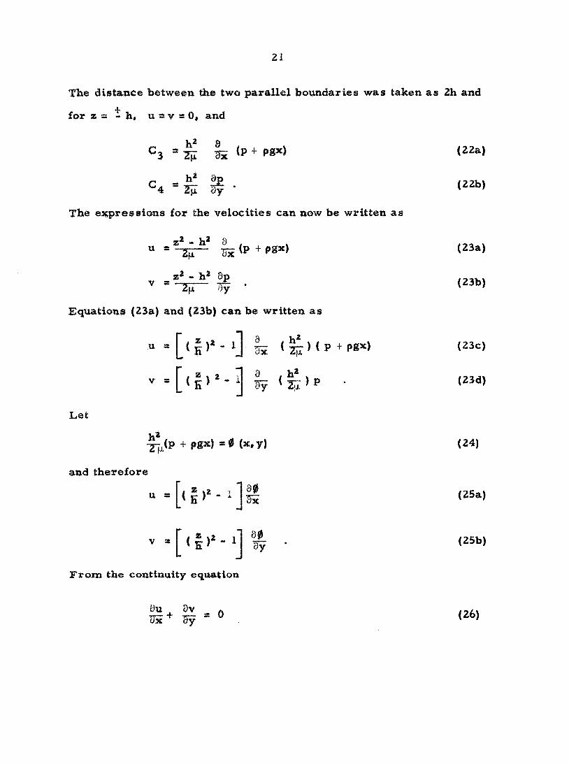
The distaace between the two parallel boundaries was taken as 2h and X
for zss-h, u»vaO, and
^3 ^ S ^ PS*) (22a)
^4 ® ^ If • The expressions for the velocities can now be written as
" = <p + ps'" <"»'
' -'4 '̂If • <""> Equations {23a) and (23b) can be written as
" = I U)'- H I; <zs)<P + PS''> ("O
Let
v = [ ( | ) ^ - ^ | y ( ^ ) p . ( 2 3 d )
+ f**l • * (*. y) (24)
and therefore
u
*[(1)' -'] b0 3y
From the continuity equation

22
and tMs imposes the condition on 0 so that
82'£ ^ 0 (27)
and therefore 0 is
are
03j.t 0y2
potential function. The boundary conditions at infinity
U s i i f - I tr oo (28)
Also, at any solid boundary the normal component of the velocity must be
zero. Therefore from the condition at infinity
80
80 "ly
a U 00
oo (29a)
(29b) oo
and at any solid boundary the function 0 must be such that the normal
components of u and v are zero.
One of the fundamental theorems of classical potential flow theory
is that a potential function is uniquely defined by the conditions at infinity
and the shape of the geometrical boundary. It therefore follows that the
function 0 for the viscous flow problem Is the same as the potential func
tion obtained from ideal fluid flow theory. Equations (23c) and (23d)
can be written as
u = [ ( | ) ' - l ] ̂ (30a)
(30b)
where u^ and v^ are the components of velocity of an ideal fluid flowing

23
past the prescribed body.
Hele-Shaw (7) made use of Eqimtlons (30) in developing a technique for
visualizing potential flow patterns. He inserted various shapes between
closely spaced glass plates in which water was flowing and injected dye
into the system to determine the streamlines. The patterns obtained were
identical with those predicted analytically except near the sold boundar
ies where the assumptions made in the analysis are no longer valid.
Since the flow parameters can be readily calculated for the parallel
plate set-up, it was decided to use this type of flow channel for the
photoviscous fluid studies. Of course all results are subject to the
assumptions made in the derivation of the equations.
The channel was designed so that the incident polarized light ray passed
through the fluid in the z-direction. One disadvantage to the set-up is
that the velocity gradient in z-direction gives rise to systems of shearing
stresses which have components parallel to the light ray ^yz^'
components in planes normal to the ray (S„ • S ). However, it was
assximed that these stresses would give no optical effect. Frocht (5) has
shown that stresses of the type described contribute nothing to the photo-
elastic effect in solids.
The flow around two different geometrical boundaries was studied.
The shapes selected for the investigation were a circular cylinder and a
half-body. These bodies are illustrated in Figure 4.
The potential and stream functions for these two shapes are well
known from ideal fluid theory. For the cylinder
0 s U r cos 0 c 00 1 + <1 (31 )

Z4
ol
Circular cylinder
Half-body
Figo 4 - Sections of bodies used in flow studies

25
T k = U r sin ©
C 00 (32)
and for the half-body
®hb ® ^00
sc XjF. ^hb • -oo
r cos 0 - b In r
r sin 0 ' b 0
(33)
(34)

26
EXPEEIMENTAL INVESTIGATION
The primary objective of the experimental investigation was to deter
mine the isoclinic and fringe pattern for flow around the cylinder and the
half-body. In order to obtain the desired results two major pieces of
equipment were required, a polariscop® and a flow channel. This section
is devoted to the description of this equipment and the double-refracting
fluid. An outline of the procedure which was followed in obtaining the
experimental results is also included.
Determination of Fluid Properties
The selection of a suitable fluid was, of course, of prime importance
for the experimental investigation. The desired fluid was one which was
sensitive* stable when in contact with other materials, and easily pre
pared. As previously mentioned the milling yellow solution met all of
these requirements.
The method used in preparing the solution was the same as that given
by Peebles, Garber, Jury (14) in their first report. A solution of the
milling yellow dye and distilled water was made containing i per cent by
weight of the dye. This solution was then evaporated until a more concen
trated solution was obtained. Several different concentrations were used
and it was found that observable double refraction occurred for concen
trations between approximately i. Z and 1. 9 per cent. The more con
centrated solutions could be diluted with distilled water to obtain new

27
solutions. The values for the concentrations were obtained by evaporat
ing a weighed sample in an oven in which the temperature was maintained
at approximately 95 C- It was found that all solutions used had, for all
practical purposes, the same density as water-
The viscosity determination was made with a MacMichael viscometer.
This device consists of two concentric cylinders between which the fluid
is placed. The inner cylinder is suspended by a wire and is free to
twist. The outer cylinder rotates with a constant angular velocity and a
velocity gradient between the two cylinders is established. When the
system is in equilibrium the inner cylinder has an angular displacement
relative to its original position. If the properties of the wire supporting
the inner cylinder are known the torque exerted by the fluid on the inner
cylinder can be calciilated. The torque can then be related to the shear
ing stress which is exerted on the cylinder. The wires used in this
investigation were calibrated by the National Bureau of Standards and
the "wire constant" was Isnown in terms of the torque per MacMichael
degree.
Viscosity measurements were obtained for a 1.63 per cent solution
at a temperature of 26 • 1 C. Data were obtained for only one solution
since the actual values of the viscosities were not used in the investiga
tion and only the general characteristics of the viscosity versus velocity
gradient curve were considered to be of importance at this time.
Values of MacMichael degrees versus angular velocity of the outer
cylinder were plotted as shown in Figure 5. Since the shearing stress
is proportional to the MacMichael degrees and the velocity gradient is

m
-
( /
/ 3
1 1
1 1
-
/
/
o'°
c
/ O / )
1
/
• / / 34 Wire
/
• / 1
/
-/ /
,, 1 1 1 I
0 10 20 30 40
AHOULAH VSLOCITY OF OUTER CYLINDEH - (BPM)
® 6 - ViBCoaity characterictlee of milling yellow solution
50

29
proportional to the angular velocity of the cylinder, this plot act^lally in
dicates the relationship between the shearing stress and the rate of strain.
For a true Newtonian fluid this curve should be a straight line passing
through the origin. As shown by Figure 5 this is not the case for the
milling yellow solution and therefore it is classed as a non-Newtonian
fluid. The lowest angular velocity which could be obtained with the vis
cometer was approximately 6 RFM. The dashed portion of the curve is
simply an extrapolation of the observed data. As mentioned in the pre
vious section the extrapolated portion of the curve was approximated with
a straight line and Newtonian relationships were aasximed to be vailld In
this region.
It was observed that the optical sensitivity of tlie fluid decreased with
age. For periods up to one month no observable changes occurred, but
for longer periods of time the sensitivity decreased.
Description of Optical Equipment
The components of a standard circular polarlscope are the light
source, polarizer, analyzer and two quarter-wave plates. It was desir
able to have an optical field approximately 10 to 12 Inches In diameter for
the photovlscous fluid studies.
Two polaroid discs and two quarter-wave plates, all 12 Inches In
diameter, were obtained from the Pioneer Scientific Corporation. These
circular plates were mounted in wooden frames in such a manner that they
could be rotated through 360 degrees.

30
The light source consisted of two staggered banks of "green" fluores
cent lamps. A total of sixteen lamps were used. A piece of white paper
placed in front of the bank provided an additional amount of diffusion.
The spectral curves for the fluorescent lamps, published by the General
Electric Company, indicated a range in wave lengths from approximately
4600 to 6400 Angstrom units. Thus the light source could not be consid
ered monochromatic.
A picture of the polariscope is shown in Figure 6a and a picture of
the inside of the light source is shown in Figure 6b,
Description of Flow Channel
The main channel (channel A) which was used is shown in Figure 7.
The channel was constructed of 1/8 inch Plexiglass sheet which was either
glued or bolted together. The flow rate was regulated by the pinch clamp
at A and a constant head was maintained by the overflow weir. The chan
nel was designed so that the front plate covild be removed and various
geometrical shapes could then be bolted in place. It was discovered that
either glass or Plexiglass was the best material to use for areas in con
tact wife the fluid since the milling yellow solution did have a tendency to
crystalliae whenever it came in contact with metal.
A second channel (channel B| was used for some tests and is shown
in Figure 8. It was also constructed of 1/8 inch Plexiglass. Channel B
was designed so that the effect of the velocity gradient in the direction
of the incident light ray would be reduced. This was accomplished by

Fig. 6a. Photograph o£ polariscope and channel A
Fig. 6b. Photograph of diffused light source
Fig. 6. Photographs of experimental equipment

Supply Supply
Overflow weir Machine
i/Bcrew
Drain
35"
Test section
cr'
hutber gasket
Pinch clsunp A
• Diecharge
Figo 7 - Sketch of channel A

Supply
Overflow
weid 10"
Polariscope outline
Flange — Plexiglass
_il_
Pinch clamp B
I Drain h 10
Discharge
Section A-A
Figo 8 - Sketch of Channel B

35
increasing the distance between the walls of the channel in the direction
of the ray. The flow rate was regxalated by the pinch clamp at B and a
constant head was maintained by the overflow weir.
Test procedure
For a given series of tests the following information was obtained.
1. The isoclinic pattern.
2. The stress pattern.
3. The discharge.
The complete isoclinic pattern was determined by rotating the crossed
polariaer and analyzer together through a total angle of 90 degrees. For
a given series of tests, photographs were taken for each 10 degrees of
rotation. The isoclinics were removed by the insertion of the quarter-
wave plates and the resulting stress patterns, if any, were photographed.
Discharge data were obtained by collecting a given volume of fluid in a
known interval of time.
The photographs were taken with a 35-mm camera with attached
portrait lens using Tri-X film. The optical patterns in the fluid were
sufficiently steady so that as long an exposure time as necessary coiild
be used. For most tests the shutter speed was l/iO sec.
Since the age of the fluid apparently affected its optical properties
all tests in a given series were performed in as short an interval of
time as possible, usually 2 to 3 hours in duration. The temperature of
the fluid for all tests was 21 t 1 C.

36
SESULTS
General Experimental
For the first series of tests in channel A a 1.63 per cent solution was
used. Photographs were obtained for flow around the circular cylinder
at free-stream velocities of 0. 0092 ips and 0. 016 ips and for the half-
body at velocities of 0. Oil ips and 0. 033 ips. A representative number
of the photographs for this series is given in Figures 9 through 18. The
photographs have been enlarged to the actual size of the flow channel.
It was observed from this series of tests that the isoclinics were readily
obtained, but the isochromatics were absent. (See Figures 13 and 18),
The polarizer angle has been used to characterize the isoclinics and is
defined as the angle between the free-stream velocity direction and the
polarizer.
A second series of tests for the cylinder and half-body was run using
a 1.80 per cent solution. Photographs were obtained for the cylinder
at free-stream velocities of 0. 025 ips and 0. 043 ips and for the half-
body at velocities of 0. 033 ips and 0. 05i ips. For this heavier concen
tration some isochromatics were visible in the channel. The predomin
ant colors were red, green and yellow but the colored bands were not
sharply defined. Figures 19 and 21 show the 45-degree isoclinics for
the cylinder and half-body respectively for the i.80 per cent solution
and Figures 20 and 22 are photographs of the same field with the isoclinics
removed. The dark area above the cylinder and half-body on the vertical

Fig. 9. Isoclinics for ilow around circular cylinder in channel A
Velocity K 0. 016 ips Concentration = 1. 63%
Polarizer angle 3= 90®


Fig. 10. Xsociinics for flow around circtxlar cylinder in channel A
Velocity s: 0. 016 ips Concentration « 1. 63% Polarizer angle s 70°


Fig. 11. Isoclinics for flow around circular cylinder in channel A
Velocity s 0. 016 ips Concentration = 1. 63% Polarizer angle = 45°


Fig. 12. Isoclimcs for flow around circular cylinder in channel A
Velocity = 0. 016 ips Concentration = 1. 63% Polarizer angle = 20®

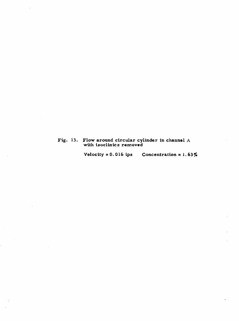
Fig. 13. Flow around circvilar cylinder in channel A with isoclinics removed
Velocity = 0. 016 ips Concentration = 1. 63%

46

Fig. 14. Isoclinics for flow around half-body in channel A
Velocity » 0. 033 ips Concentration » 1. 63% Polarizer angle =! 90


rig. 15. Xsoclinics for flow around half-body in channel A
Velocity » 0. 033 Ips Concentration » 1. 63% Polarizer angle » 70


Fig. 16. Isoclinics for flow around half-body in channel A
Velocity « 0. 033 ips Concentration = 1. 63% Polarizer angle « 45®


Fig. 17. Isoclinics for flow around half-body in channel A
Velocity s 0. 033 ips Concentration s 1. 63% Polarizer angle « 20°


Fig. 18. Flow around hall-body in channel A with isoclinics r«moved
Velocity » 0. 033 ips Concentration = 1. 63%


Fig. 19. Isoclinics for flow aroimd circular cylinder in channel A
Velocity » 0. 025 ips Concentration = 1. 80% Polarizer angle a 45®


Fig. 20. Flow around circular cylinder in channel A with isocUnics removed
Velocity = 0. 025 ips Concentration » 1. 80%


Fig. 21. Isoclinics for flow around half-body in channel A
Velocity ss 0. 033 ips Concentration = 1. 80% Polarizer angle » 45®


Fig. 22. Flow around half-body in channel A with isoclinics removed
Velocity « 0. 033 ips Concentration « 1. 80%


Velocity » 0. 025 ips Velocity =s 0. 043 ips Velocity « 0. 046 ips
Fig. 23. Isotropic points in flow around circular cylinder in channel A
Concentration =s 1. 84%


Velocity s 0. 033 ips Velocity = 0. 051 ips Velocity =s 0, 058 ips
Fig. 24. Isotropic points in flow around half-body in channel A
Concentration =s 1. 84%

68

Fig. 25. Extinction of light for parallel flow in channel A
Velocity s: 0. 015 ips Concentration = I. 84% Folariaer angle = 90°


Fig. 26. Extinction of light for parallel flow in channel A
Velocity s 0. 015 ips ^ Concentration « 1. 84% Polarizer angle =70


Ftg. 27. of light for parallel flow in channel A
Velocity » 0. 015 ips Concentration = 1. 84% Polarizer angle s 45°


Polarizer angle = 0
Polarizer angle s 20°
Polarizer angle =45*^
Fig. 28. Bxfcinction of light for parallel flow in channel B
Velocity s 0. 0032 ips Concentration = 1. 84%


Valoctty =t 0
Velocity = 0. 0015 Ips
Velocity s 0. 0058 ips
Fig. 29. Stress patterns for parallel flow in channel B
Concentration * 1. 84% Polariaser angle = 0°


79
axis of symmetry appeared to be an isotropic point, i.e. a point in the
field which blacks out for all polarizer angles. An isotropic point also
appears in Figure IS. Figures 23 and 24 show the change in the position
of the isotropic point a® the free stream velocity was varied. A discus
sion of the significance of the isotropic point is given in the next section.
Tests were also performed for parallel flow in both channel A and
channel B. Figures 25, 26 and 27 show the extinction of light in channel
A at a velocity of 0. 015 ips as the crossed polarizer and analyzer was
rotated through 45 degrees. As the rate of flow was increased iso-
chromatics appeared in the channel but again were not sharply defined.
The first color (redy appeared in the central region of the channel and
moved to the outside as the rate of flow was increased. The laminar
flow pattern appeared to break down at a velocity of approximately 0. 09
ips. At this velocity the optical pattern became very irregular. Figure
28 shows the extinction of light for parallel flow at a velocity of 0. 0032
ips in channel B as the crossed polarizer and analyzer was rotated through
45 degrees. Figure 29 indicates the change in the fringe pattern in
channel B as the velocity increased. As the velocity was increased be
yond 0. 0058 ips the fringes became indistinguishable. In channel b the
intensity of light was decreased considerably from the intensity in channel
A since the light had to pass through a greater thickness of fluid.
Analysis
The directions of the xy- principal stresses in the fluid field can be
calculated since the equations describing the motion of the fluid are known.

80
The xy-principal stresses are defined as the principal stresses resulting
from the stress components and S^^.. Frocht (5) has pointed out
that for solid photoelasticity an incident polarized light ray, which is
normal to the xy-plane of the medium, is resolved into components
which are parallel to the scy-principal stresses. If we consider the
triangular element of Figure 30 an expression for the xy-principal stress
t
nt
xy
Fig. 30. xy-stress system at a point
directions can be determined in terms of the shearing and normal stres
ses. This expression is, of course, the same as the conventional one de
veloped for solids and is
tan 2a = . (35)
As given previously, for Newtonian fluids the expressions for the stresses
are

81
Sy = -p+2]. (13b)
S » 'X x y ^ - s] • <•"> Substitution of Equations (13a), (13b) and (i3d) into Equation (35) gives
tan 2a = ^ (36)
since th© viscosity and pressure terms cancel. For flow in channel A
the velocity components can be expressed as
[<?>'->] If 1] ^
and therefore Equation (36) can be written
020
tan 2a = . (39)
V = (
:IX -.:?y
It is noted that the direction of the xy-principal stresses are independ
ent of z. Equations (31) through (34) give the velocity potential and stream
functions for the shapes considered and these equations can be differen
tiated to give for the cylinder
"oo 35r5^ = sin 3 0 (40)
2a' U
'9x' c)y ~ ~3 cos 3 0 (41)

82
and for the half-body
(42)
^'pbh tsrsy ' —
C O S 2 0 • (43)
It was more convenient to express the results in polar coordinates than
rectangtslar coordinates.
Eqwationa (40) thromgh (43) substituted into Equation (39) give the xy-
principal stress directions fot the cylinder as
Equations (44) and (45) indicate that the isoclinics should appear as a
series of radial lines as the crossed polarizer and analysser was
rotated. Figures 9 through 12 and Figures 14 through 17 show that the
observed isoclinic patterns were not radial lines.
It was felt by the author that this discrepancy could be attributed to
one of two things. The assumption that the fluid had Newtonian charac'-
teristics at low rates of flow was false or the directional effect in the
fluid was governed by some factor other than the xy-principal stress
directions.
» c ' !« • + (44)
and for the half-body as
» e . e + 90° (45)

83
In. order to check on the latter possibility an attempt was made to
relate the direction of the optic axes at a given point in the fluid to
various other flow parameters. It was recognized that as a particle of
filuid moved along a streamline the direction of the streamline and
principal stresses was constantly changing. Such parameters as the
rate of rotation of the streamline, rate of rotation of the principal stress
planes and streamline angle were considered. No satisfactory correla
tion was obtained.
The effect of the non-Newtonian characteristics of the fluid was not
easily obtained. However, in the flow field there are two regions in
which the directions of the xy-principal stresses can be determined re
gardless of the nature of the fluid. One area is along the vertical axis
of symmetry where the shearing stress is asero due to the symmetry
of the flow pattern. Along this axis it was expected that the principal
stsress directions woiild be horizontal and vertical for all fluids and
extinction would occur for a polarizer angle of 90 and 0 degrees. This
was observed for both the cylinder and half-body as shown in Figures
9 and i4.
The other region in which the xy-principal stress directions are
known is along the surface of the cylinder and half-body. Adjacent to
the solid boundaries the fluid is stationary and subjected to a condition
of pure shear. The xy-principal stress directions are 45 degrees from
the tangent to the surface. Since this stationary layer Is extremely thin
it is diffictilt to detect any dark areas near the boundary except at points
where the Isoclinic from the field goes into the boundary. At these

84
points it was found that the optic axes in the fluid coincided with the pre
dicted principal stress directions. (See Figures 9 through 12 and
Figure 14J.
Although not conclusive, the data supported the theory that the optic
axes in the fluid could be predicted from the xy-principal stress direc
tions if the true stresses could be determined.
The light was extinguished for all polarizer angles in the vicinity
of the wake of the cylinder. This phenomena has not been explained but
it is believed by the author to be due to vortices which are shed from
the cylinder.
The parallel flow tests in channels A and B also yielded results which
could not be explained using Newtonian theory. For parallel steady flow
values of the stresses as given by Newtonian theory are
and S - S « 0. Therefore it was expected that the light would be extin-X y
guished when the polariaier angle was 45 degrees and also a zero fringe
should appear along the centerline of the channel since the shearing
stress is also zero along this line. For channel B the expected re
sults were observed as shown in Figures 28 and 29. H-wever, in
channel A, maximum extinction occurred for a polarizer angle of 90
degrees and a zero fringe did not appear. The primary difference be
tween the conditions in the two channels was the relative magnitude of
the velocity gradient { ^ ) in the direction of the light ray. For channel o z
A this velocity gradient was the predominant one whereas in channel B
this gradient was greatly reduced. It appeared that the velocity gradient
in the z-direction had an effect on the observed optical patterns.

85
As a. |>ossible e3C|>laimtion of the observed phenomenon it was pro
posed that normal stresses, not predicted from Newtonian theory, are
apparent shearing stress. The apparent shearing stress is defined as
the stress calc^ilated from Newtonian theory. It was further proposed
that the magnitude of the normal stresses increased as the magnitude
of the apparent shearing stress increased.
Therefore in channel A where the velocity gradient in the z-direction
is much larger than the gradient in the y-direction the predominant
stress affecting the optical pattern would be a normal stress in the
direction of the streamline. For this condition the xy-principal stress
directions would be parallel and normal to the streamlines as shown in
Figure 31 and no zero fringe would appear. In channel B the velocity
gradient in the z-direction is small compared with the gradient in the
y-direction and therefore the principal stress directions are at approxi
mately 45 degrees to the streamline as shown in Figure 31 and a zero
fringe should appear. These facts are in agreement with the observed
phenomena.
Another discrepancy which appeared and not accounted for with the
Newtonian theory was the isotropic point. In order for an isotropic
point to exist two conditions must be satisfied.
developed along the streamlines and the lated to the
' ' xy (46)
(2) - sy x 0. (47)

64
Direction of flow
'xy
Principal stress directions
xy
Channel A
Principal stress directions
Channel B
Figo 31 - Principal stress directions in parallel flow

87
If Equations (44) and (45) are satisfied then
tan 2a s ^ (48)
and the directions of the xy-principal stresses are indeterminant.
From Equations (13), (37) and (38), which are based on Newtonian
theory.
- s y =
8^0 BxSy
sily
( g ) ' - 1
( £ ) ' - 1
These stresses were evaluated and give for the cylinder
4}a u, 00
xy
S • S »
j r
4|ia2 u o o
sin 3 ©
cos 3 0
< e ) ' -
and for the half-body
2^ u^b
xy sin 2 0 (I)' - 1
2n U b - S,, = cos 2 ©
^ y
(49)
(50)
(51)
(52)
(53)
(54)
The isotropic points appeared along the positive x-axis (0 =0). Thus
for the cylinder
xy
S - S X y
0
( r ) '
(55)
(56)
and for the half-body

83
S »0 xy
S. 2 b (JL oo
X ( 2 ) > - 1 (57)
Thus condition { 1 } is satisfied but condition (2) is not. However, if
additional normal stresses exist condition (2) is satisfied for the cylinder
if
s* - s* s-X y
4 av ' I (58)
and for the half-body
S' - S* a-X y
2 u ^ b , x ( S - i (59)
where the prime terms represent the additional normal stresses. Equa
tions (58) and (59) make it possible to calculate the approximate magni
tude of the additional normal stresses since the right-hand side of the
equation is known. However, since these terms are based on Newtonian
theory, only an order of magnitude for the normal stresses could be
e3q>ected.
The location of the Isotropic points was determined from Figures 23 si. - s*.
and 24 and the maximum value of the quantity was evaluated.
This expression was plotted in Figure 32 versus the maximum velocity
gradient in the'z-direction.
The expression for the velocity component u is
u = ( i ) ' (30a)
and therefore the maximum gradient in the z-direction is

oao
Circular
cylinder \
Half tody
MAXIMUM APPARETT RA.TE OF STBAIN- ̂
Figo 32 - Variation of apparent normal stress rate with apparent rate of strain

90
, 9tt. 2 „ (60)
8u, For the cylinder the expression for ( ^ along the x-axis is
2 U, . B u . * 15^ f
CO
' xn
and for the half-body
* B z ' m
1 - ( I (61)
2 0 GO i - (62)
Since each isotropic point covered a small area the value of r which
bounded the isotropic point along the x-axis was determined and the
normal stress rate calctilated for the limiting values of r. The range of Si - Si
values for x was plotted and an average curve drawn in. The { i
parameters which have been plotted we re termed the "apparent" normal
stress rate and velocity gradient since they were calculated from the
Newtonian equations. Figure 32 shows that the apparent normal stress
rate increases rapidly as the apparent velocity gradient is increased.
Recently Ijodge (10), (11), (12) has shown analytically the existence
of normal stresses in plane parallel flow of solutions made up of net
works of chain molecules. High-polymer solutions of this type are
known to be double refracting, philippoff (16) measured the normal
stresses and shearing stresses in a double-refracting high-polymer
solution and calculated the directions of the principal stresses. He
found that the optic axes in the fluid corresponded to the calculated
principal stress directions.
From the analysis of the experimental data it was concluded that the
behavior of the fluid could not be explained on the basis of Newtonian

91-92
theory and therefore, even at low rates of flow, the fluid must be consid
ered as non-ffewtonian. This fact is important since it affects the tech
nique which can be used for the prediction of flow patterns.
Proposed Method for the Prediction of Flow Patterns
In order to develop a prediction technique certain characteristics of
the fluid must be known or assumed. In the following analysis it has
been assumed that;
(1) The optic axis in the fluid coincides with the principal stress direc
tions and the magnitude of the maximum shearing stress is related to the
retardation of the component light rays as they pass through the fluid.
(2) Newtonian relationships cannot be used.
In the previous section experimental evidence has been presented
which supports both of these assumptions for the milling-yellow solutions.
The first step in the proposed technique is the calibration of the fluid.
The calibration can be carried out in a concentric-cylinder apparatus
similar to the MacMichael viscometer. If the gap between the outer and
inner cylinders is small the rate of strain (velocity gradient) can be
evaluated as the peripheral velocity of the outer cylinder divided by the
gap width. If the properties of the wire which suspends the inner cylinder
are known the shearing stress exerted on the cylinder can be evalu
ated. A small polariscope can be used with the apparatus and the principal
stress directions and fringe order can be determined. It can readily be
shown that
®xy = 2 " (^3)

93
where a Is the angle between the plane on which S acts and the "^y
principal stress direction. Since both S and a are measured the xy
maximum shearing stress can be evaltiated. The shearing stress S xy
can be plotted versus the rate of strain and can be plotted versus
the fringe order. It shotild be noted that in the above analysis no New
tonian relationships have been used. If the fluid is Newtonian S « xy
and a a 45® lor all rates of strain, max
In the general two-dimensional field under study the isoclinic
pattern* the fringe pattern and the discharge must be determined.
This can be accomplished with the same type of equipment which was
used in the present investigation. At a given point in the fluid field
the fringe order Is known and from the calibration curve the value of
®max obtained. Since a is also known Equation (63) can be used
to determine S . The relationship between S „ and the rate of strain xy xy
can be written In the form
Eate of strain » £ (64)
or
If + S = '<sxy) • (^5)
Since a stream function ^ can be defined, regardless of the nature of
the fluid, the velocities can be written as
and Equation (65) can be written as

94
- « f(S ) . (66) 9y^ hx'' ^
The calibration data give the relationship between the shearing
stress S „ and the rate o£ strain so that if S is known the function sry xy
f^S^y) can be determined. Therefore the right hand side of Equation
(66) can be determined throughout the field for the general case. The
stream function ^can then be determined throughout the field by a con
ventional numerical technique. Rosenberg (13) has outlined a suitable
numerical method for a Newtonian fluid which could be applied to
Equation (66). The lines of constant ^ will give the streamline pat
tern in the flow field. The numerical work can be checked since the
solid boundaries in the system must form a equals constant curve.

95
SUMMARY AND CONCLUSIONS
in tWs investigation the isoclinic and isochromatic patterns for two-
dimensional flow around a circular cylinder, a half-body and for
parallel flow were obtained for several milling-yellow solutions. The
geometry of the experimental apparatus was such that the Newtonian
equations describing the flow were known. An attempt was made to
relate the optical patterns to various flow parameters but no satisfac
tory correlation was obtained. For areas in the fluid field where the
directions of the principal stresses could be evaluated without recourse
to the Newtonian relationships it was found that the optic axes in the
fluid coincided with the principal stress directions.
The existence of normal stresses, which could not be accounted
for from Newtonian theory, was proposed and experimental evidence
was presented to support this idea. The magnitude of the apparent
normal stress rate was calculated and related to the apparent rate of
strain. In general the experimental data indicated that the behavior
of the fluid was non-Newtonian.
A method was proposed for predicting the streamlines of two-
dimensional flow around submerged bodies. In order to develop a satis
factory technique two assumptions were made concerning the charac
teristics of the fluid. The assumptions used were supported by experi
mental observations. The type of calibration data which is required
for prediction was indicated and a suitable experimental set-up was

96
described. The method to be used in obtaining the streamlines from
the experimental data was outlined.
In the author's opinion the use of the milling yellow solution will
prove of value as a qualitative and quantitative fluid mechanics re
search tool. It is recommended that further studies be made in this
area.

97
EECOMMENDATIONS FOR FURTHER INVESTIGATIONS
In this thesis the emphasis has been placed on the problem of flow
around submerged bodies. Of course there are many other types of
problems in the £luid mechanics field for which photoviscous fluids
could be used. Studies could be made on flow through orfices, Venturi
meters* weirs, and various pipe fittings.
Regions of turbulence are easily detected with the milling yellow
solutions. As mentioned in the Review of Literature, studies on the
onset of turbulence in tubes have been made using a photoviscous fluid.
Since the milling yellow solution Is more sensitive than the fluids pre
viously used, further work in this area would be of value.
C^e problem of great interest at the present time is flow in boun
dary layers. Since the thickness of the layer is usually very small,
measurements from conventional techniques are difficult to obtain.
It is the opinion of the author that photoviscous fluids could be used to
advantage in boundary layer studies. There does not appear to be
any particular difficiilty In obtaining fringes near solid boundaries.
In fact, in this investigation the most sharply defined fringes appeared
near the fixed boundaries.
It is recommended that the concentric-cylinder calibration device
be constructed and used for the prediction of the flow pattern around
some specified object. Although the proposed method for predicting
streamlines is relatively simple, the construction of the calibration

98
equipment and the development of the experimental technique will con
stitute a major undertaking.
Further studies which are related to the evaluation of the apparent
normal stresses and to the structure of photoviscous fluids woxild be of
considerable value.

1
2
3
4
5
6
t
s
9
10
11
12
99
JLHrERATURE CITED
Alcock, E. JD. and Sadroti, C. L. An optical method for measuring the distribution of velocity gradients ia a two dimensional flow. Phys. 6: 92-95. mS.
Binnie, A.M. A double refraction method of detecting turbulence in liquids. Froc. Fhys. Soc. (London). 57: 390-402. 1945.
and Fowler, J. S. A study by a double refraction method '• of"ilie development of turbulence in a long circular tube. Proc. JRoy. Soc. A 192j 32-44. 1947.
Dewey, D. E. Visual studies of fluid flow patterns resulting from streaming double refraction. Unpublished Doctoral Dissertation, Massachusetts Institute of Technology. 1941.
Frocht. M. P|jOtoelasticity. Vol. 2. p. 333-338. New York. John Wiley and Sons. 1941.
Hauser, E. A. and Dewey, D. R. Study of liquid flow. Ind. and JEng. Ghem. 31; 786. 1939.
Hele-Shaw, M,. S. Investigation of the nature of the surface resistance of water and of streamline motion under certain experimental conditions. Trans. Inst. Maval Architects. 40:25. 1898.
Humphrey, E. H. Demonstrations of the double refraction due to motion of a vanadium pentoxide sol and some applications. Proc. Phys. Soc. (London). 35: 217-218. 1923.
Leaf, W. Fluid flow study of locomotive firebox design. Mech. Engr. 67: 5S6-590. 1945.
Lodge, A. S. Variation of flow birefringence with stress. Nature. 176: 838-839. 1955.
A network theory of flow birefringence and stress in concentrated polymer solutions. Trans, of the Faraday Soc. 52, no. 397: 120-130. 1956.
A "finite strain'* theory of flow birefringence, stress, iiSr elastic recovery for an idealissed solution of long-chain molecules. Paper presented at the 9th International Congress of Applied Mechanics. Brussels. Sept. 1956.

100
13 . Maxwell, J. C. On double refraction In a viscous fluid in motion. Froc. B,oy. SoC. 22: 46-47. 1873.
14. P®«W®s, F. N., Garber, H. J. and Jury, S. H. Preliminary Studies of flow phenomena utilissing a double refracting liquid. Proc. Tbird Midwestern Conference on Fluid Mechanics. Minneapolis. Univ. of Minnesota Press. 1953.
15. , Frado»» S W. and Honeycutt, E. H.» Jr. A study of liTm&ar flow j^enomena utilising a dotdjly refracting liquid. Univ. of Tennessee. Eng. Exp. Sta. and Dept. Chem. Engr. Progress Eeport 1- 1954.
16. Philippoff, W. Flow birefringence and stress. J. of Appl. Phys. 27; 984*989. 19S6.
17. Prados, J. W. and Peebles, F. N. Determination of flow double refraction properties of aqueous milling yellow dye solutions. Univ. of Teimessee. Eng. Exp. Sta. and Dept. Chem. Engr. progress Report 2. 1955.
18. Rosenberg, B. The use of doubly refracting solutions in the investigation of fluid flow phenomena. Navy Dept. The David W. Taylor Model Basin. Report 617. 1952.
19. Ullyott, P. Investigation of flow in liquids by use of birefringent colloidal solutions of vanadium pentoxide. Trans. A. S. M - E. 69: 245-251. 1947.
20. Wayland, M. Streaming birefringence as a hydrodynamic research tool - applied to a rotating cylinder apparatus above the transition velocity. J. of Appl. Phys. 2o: 1197*1205. 1955.

101
ACKNOWLEDGE MENTS
The author takes this opportunity to express his sincere apprecia
tion to Dr. Olenn Murphy, Head of the Department of Theoretical
and Applied Mechanics, for his guidance during this investigation.
Dr. Murphy's continued encouragement and advice were invaluable.
The author wishes to thank his wife, Ann, whose patience and under
standing made possible the completion of this work.